Embed Size (px)
Citation preview
1
VITRIFIED FORTS AS ANTHROPOGENIC ANALOGUES FOR ASSESSMENT OF LONG-TERM STABILITY OF VITRIFIED
WASTE IN NATURAL ENVIRONMENTS
R. SJÖBLOM1, H. ECKE2 & E. BRÄNNVALL1 1Division of Waste Science and Technology, Luleå University of Technology, Sweden.
2Vattenfall Research and Development AB, Sweden.
ABSTRACT The areas natural analogues, vitrified forts, combustion technology, and vitrified waste have been reviewed. The purpose was to identify if investigations of vitrified rock in hillforts might be warranted for assessing the long-term integrity of vitrified waste in natural environments. Wastes that are being vitrified include, ash from incineration of domestic waste, contaminated soil and fission products from reprocessing of spent nuclear fuel. It was found that vitrified materials in at least 200 hillforts constitute good anthropogenic analogues to vitrified waste. The compositions vary considerably from site to site and even within one site, and may correspond relatively well to the spans of parameters in the various vitrified wastes. Glasses in vitrified forts compare favourably to archaeological artefacts which are soda and potash based and consequently have a different corrosion behaviour, and may weather too quickly. Natural glasses might be too limited in composition variation and are perhaps also too durable. Combustion technology considerations based on quality of heat analyses indicate that at least some of the vitrifications of hillforts were carried out with the specific purpose of achieving strong and durable constructions. This makes it considerably easier to envisage how the vitrifications might have been carried out, and this, in turn, facilitates fruitful comparisons between anthropogenic analoges and modern vitrified wastes. Keywords: long-term, analogue, vitrification, hillfort, waste, glass, leaching
1 INTRODUCTION Sustainability awareness has probably been around for at least as long as agriculture, but modern verbalizations of the principle of sustainable development appeared for the first time in the year 1972 [1]. In a report to the United Nations in 1987, the Brundtland commission stated that "Sustainable development is development that meets the needs of the present without compromising the ability of future generations to meet their own needs" [2].
The protection of the basis for subsistence for future generations is closely related to the polluter pays principle which in its implementation into Swedish legislation has no upper limit and no endpoint in time [3]. Amongst other things, the polluter pays principle calls for the present generation to manage its own waste, and - for cases where this may not be practicable or feasible - to at least develop the appropriate technology and accumulate the funds needed.
It is, however, not difficult to find examples of where the needs of the present have been given precedence over our obligation to pass on to future generations. Compliance with the polluter pays principle has been found to be particularly difficult and treacherous in cases where it is difficult to specify the link between what we do today and what may happen in the future, see [4] and references therein.
Actually, it is not sufficient to merely protect health and the environment within the limits prescribed. It is also required that the best available technology is used, considering various circumstances.
In view of the above, one might wish to choose a waste management strategy such that it includes waste forms that possess superior chemical integrity.

2
In accordance with such a strategy, domestic and other waste in Japan is incinerated after which the ash together with some additives are vitrified at a temperature of 1 100-1 500 ºC. The products resemble obsidian which is a natural glass that can persist in soil environments for tens of millions of years with little or moderate alteration. According to [5], there were 24 such full-scale plants in Japan in 1999. Much of the reason for this is the scarcity of land [6] in combination with the possibility to use the product in geotechnical constructions [5].
Reference [7] unveils, however, that the very high energy consumption of the process has prevented it from being used commercially in most other countries.
This raises the question as to how a higher cost is to be balanced against chemical integrity, and especially such integrity in the long term.
The legal requirements on landfills and other waste disposal facilities focus on the properties of the waste forms and of the technical barriers at the time of disposal and closure, respectively. For the long term, only statements can be found, such as one from the Swedish Environmental Protection Agency which advices [8] that a landfill for non-hazardous waste must maintain its intended function for several hundred years, and a landfill for hazardous waste for thousands of years.
The polluter pays principle together with the principle of sustainable development may, however, be interpreted to imply that the protection of health and environment should be no less ambitious with regard to future generations than it is for ours. Consequently, it is warranted to investigate the long-term behaviour of waste forms and to attempt to determine how well potentially harmful components of interest are isolated in the long term. This immediately raises the question of the validity of results of short term tests to long-term behaviour, and the short answer is that one also needs long-term data from natural or anthropogenic analogues.
Of course, comparison can be made – and has been made – with natural glasses as well as with archaeological objects and specimens. But there is one important category of archaeological glasses that – to the best of the knowledge of the present authors – has not been included in such considerations, and this is glass in vitrified forts. In such forts, stones are joined together by vitrified rock material. This is of particular interest in the present context because such glass generally has a different composition as compared to archaeological glass objects, it has been exposed to near surface weathering in a natural soil environment and because it may have been prepared with the specific intent of being durable in an outdoor environment based on the experience of a number of generations.
2 OBJECTIVE AND SCOPE
The main objective of the present work is to investigate if, and in such a case how, vitrified archaeological rock material from hillforts might be utilized in order to predict long term properties of vitrified waste in natural soil environments.
This objective is related to the question if the vitrification in the forts was made for constructive purposes. If this is the case, then one might expect that a comparatively easily fusible material was selected that would also form a durable glass. This would also make it possible to assess what processes might have been used for the melting. Such knowledge is essential when comparison is to be made between historical hill fort glasses and modern vitrified waste. A second objective is therefore to attempt to identify for what purpose and how the vitrification could have been made in the hillforts.
The scope of the present work is to search for information in the areas of uses of natural analogues, vitrified forts, combustion technology, and vitrified waste. The material found is analysed with regard to the objectives above.

3
3 ASSESSMENT OF LONG TERM PROPERTIES AND THE SIGNIFICANCE OF ANALOGUES
It is important that the requirements for appropriate assessment of longevity are fully recognized. Common assumptions (and at least partial misconceptions) in this regard include the following: 1 At thermal equilibrium, all elements appear as a major element in one phase or another. 2 Thermal equilibrium can be achieved in practice. 3 Reaction rates can be estimated from the energies determined in the calculations. 4 Rates determined experimentally can be extrapolated to long times.
The four assumptions above are not valid in general. In oxide systems, minor elements do not usually form phases of their own, but are instead
included in the phases formed by the major elements in the form of solid solution. Such dilution of minor elements is strongly favoured by the gain in entropy which, in turn, strongly influences the Gibb's free energy [9].
Thermal equilibrium is rarely achieved in real oxide systems in conjunction with precipitation and dissolution as well as fractional condensation and evaporation. The reason for this is that such phenomena are usually incongruent (cf. the example below of fractional condensation of fly ash in an incinerator).
Although there are co-variations between bonding energies and rates of reactions for similar cases, there exists no general correlation. For example, the activation barrier to forming and breaking of hydrogen bonds in monomethylammonium chloride changes from about 32 to 4 kJ mole-1 in a phase transition while the strength of the bonding, as evidenced by infrared data, remains approximately the same [10].
Rates of reactions are frequently assumed to obey an Arrhenius' type of relationship. This presupposes amongst other things that the reaction in question depends on only one mechanism. The mechanisms can be widely different for different ranges of parameters (as is the case for monomethylammonium chloride with regard to temperature in the example just given). Consequently, in order for extrapolation outside the range of parameters studied to be justified, one must be able to show that the mechanisms involved are the same.
Such proof might, in principle, be achieved by detailed studies of mechanisms together with e.g. ab initio calculations, but for real systems, such as vitrified ash, this is not possible or practicable.
What remains is the possibility to use natural and anthropogenic analogues which have been about for the duration of time in question. Such analogues cannot be expected to correspond exactly to the situation for which prognoses are needed (e.g. with regard to the chemical composition or the environment), and therefore it is desirable that there exists a number of analogues that ideally span the space of parameters for the case in question.
The parameters for vitrified forts can be expected to be different from those of natural glasses and archaeological glass objects. It can therefore be expected that studies of glass from vitrified forts can add substantially to the knowledge base needed for reliable prognoses of the long term behaviour of vitrified waste.
4 VITRIFIED FORTS
4.1 About hillforts and vitrified forts A hillfort is a fortification made of earth and stone, and frequently also wood. Available dates from artefacts scatter from about 1000 BC to 1400 AD with most of the dates in the interval 500 –
4
0 BC [11, see also 12]. It has been estimated [13] that there were maybe 20 000 to 30 000 hillforts in Europe, most of which have not been identified to contain artificially vitrified walls.
Hillforts are typically located at the top of a hill, or at least at some elevated location. The function of a hillfort might have been one or more of the following: 1 Sanctuary - a temporary refuge at times of unrest. 2 Defence - with or without permanent residence. 3 Surveillance - over a passage or route in order to protect or control travel and trade. 4 Camp site for military forces.
The first record of an observation of vitrification in a hillfort originates from the year 1774 [14], and for quite some time it was believed that vitrified forts were indigenous to Scotland. However, it was estimated in 2004 that out of a total of 200 identified vitrified forts, somewhat less than half are located in other parts of the British Isles as well as in France, Germany, Bohemia, Switzerland, Italy, Portugal and Spain. One has to look for vitrification in a fort in order to find it. Some 25 years ago about two or three such sites were identified in Sweden, and seven years ago the number was 17 [15].
Heating a rock material sometimes leads to calcination instead of vitrification. Calcination means that the rock in question decomposes without melting. The most common application of calcination is the conversion of limestone (calcium carbonate) to quicklime. Forts built with limestone undergo such processes if heated sufficiently, and the result is a so-called calcined fort. From an archaeological point of view, the two phenomena of vitrification and calcination are looked upon "as essentially the product of the same process in different geological conditions" [13].
Thus, in some cases, the stones in the walls are joined by silicate based glass originating from granite, dolerite, amphibolite or sandstone [15]. Examples of compositions are shown in Figure 1. In other cases the stones are joined by a mortar-like material originating from burnt and hydrated limestone or dolostone [15].
It should be noted that the rock used for calcination was usually not the same as selected today for the manufacturing of slaked lime (calcium hydroxide), which consists almost completely of calcium carbonate. Instead local limestones were used, and they may show very different calcination and hydration behaviours. Some may need a long time for hydration while others may not only hydrate rapidly but also harden rapidly. Some may be hydraulic while others may require carbonation through exposure to air in order to harden. Further data may be found in [16, 17].
A photograph of a vitrified fort is shown in Figure 2.
4.2 Archaeological investigations The archaeological investigations have focussed on how the vitrified forts were built and used. Three scenarios for the vitrification have been discussed for over a century [13-15, 18]: 1 Constructive - the vitrification was carried out in order to strengthen the walls 2 Destructive - the timber-lacing (e.g. of the murus gallicus type) was set on fire by an enemy 3 Incidental
The proponents for the theories constitute two categories [15]: destructive - archaeologists who focus on constructive details and events of war and fires, and constructive - geologists and mineralogists who focus on thermal prerequisites and alteration temperatures.
Kresten [11-13, 15, 19] considers that iron beneficiation technology was available to the builders of the vitrified forts and consequently they had access to the charcoal and bellows required to attain the temperatures required.
Several authors have published data on chemical composition [11, 20-23] and some examples are provided in Figure 1.

5
0% 10% 20% 30% 40% 50% 60% 70% 80% 90% 100%
Incinerator bottom ash, Japan
Incinerator fly ash, Japan
Nuclear waste glass, Japan
Archaeological artefact,1500 BC, Egypt
Archaeological artefact, 9000 BC, Italy
Hill fort, Nyby, Sweden, opaque glass
Hill fort, Broborg, Sweden, clear glass
Hill fort, Broborg, Sweden, average opaque glass
Hill fort, Rhubh' Aird Ghamhsgail, Scotland
Hill fort, Shielfoot; Scotland
Natural glass, Obsidian
Examples of chemical composition of glasses
SiO2Al2O3CaOFe2O3K2OMgOMnONa2OP2O5TiO2B2O3Waste
Figure 1: Examples of compositions of various types of glasses: natural [82], vitrified forts in Scotland [23] and Sweden [11], archaeological artefacts [82], nuclear waste glass [78] and incinerator ash [5]. The compositions are figured as the oxides presented. However, iron may also
or instead be present as iron-II, and there is almost as much chloride in the incinerator fly ash to correspond to chlorides of sodium and potassium (13 % missing).

6
Figure 2: Photograph of the Broborg hillfort outside Uppsala in Sweden showing the rampart consisting of stones joined by vitrified rock.

7
The same sources indicate melting temperatures around 900 – 1 100 ºC. It should be noted that the temperatures indicate the range for the onset of melting, and that the fraction of liquid increases with increasing temperature. The onset of melting is typically determined by calorimetric means (Differential Thermal Analysis (DTA) or Differential Scanning Calorimetry (DSC)) and silicate melts may be very viscous, especially near the fusion temperature. The temperature for onset of melting may furthermore be very sensitive to the water content in the sample and in the atmosphere above. For further detail, see [24, 25].
4.3 Some combustion and heat technology considerations Apart from the iron beneficiation comparisons made by Kresten, the present authors have found little evidence in the literature [11-15, 18-23] of utilization of combustion and heat technology considerations in order to facilitate the resolution of the hundred year old debate on the purpose of the vitrification.
It is not that the incentive and feasibility for destruction of re-enforcing timber is to be questioned. Reasonably, such timbers were impregnated with tar to persist deterioration, and might readily be burned once a fort had been conquered.
Fire has been used by man on a continuous basis for about half a million years [26]. Before matches came into common use at around 1850, fire was maintained by covering charcoal with ash [27]. Therefore, utilisation of charcoal must be about as old as the use of fire. Charcoal could readily be produced in pits, and was used e.g. as a smokeless and odourless fuel for heating and cooking [28].
According to [29], the use of lime dates back some 10 000 years, and the earliest excavated lime kiln dates back to some 2 500 years BC. An ancient lime kiln would consist of a stone wall cylindrical structure filled with alternate layers of limestone and fuel, often wood [29]. Such kilns have been in use in Sweden past the middle of the last century. They were ignited at the bottom after which the fire spread upwards. They possessed the clever feature of preheating the air with the stones already conditioned and of utilising the heat in the fumes after combustion for pre-heating the stones before they were calcined by the fire.
In a carbon dioxide atmosphere, calcium carbonate dissociates at a temperature of 902 ºC [29]. In a lime kiln, dissociation starts on the surface of the stones already at around 800 ºC because of the lower content of carbon dioxide in the fumes. In modern kilns the temperature is raised to about 900 ºC for kinetic reasons. If the temperature is too high, impurities may form melt and hinder the ventilation inside the rock pieces undergoing dissociation [29]. In a historical perspective, wood is an ideal fuel for the process (e.g. relative to charcoal) since the combustion temperature is moderately low, 700 – 1 100 ºC [30] (this is the temperature in an ordinary furnace, it will be higher with pre-heating).
Modern kilns, however, use more potent fuels, such as coke which may have a combustion temperature of 1 300 – 1 500 ºC (similar to coal) [30]. The reason for using such fuels is actually not primarily the caloric value (heat of combustion), but the quality of the heat, see Section 16.7.4 in [29] which deals with high-grade and low-grade heat. A heat is said to have a high quality if much of the heat is generated at a high temperature. The more efficient the heat exchanges between rock and gases, the more important is the quality of the fuel (combustion temperature). In order for heat exchange to be efficient, the rate of progress of the fire should correspond to the size of the stones, such that large stones are not allowed to cool the process at peak temperature.
The heat of dissociation of calcium carbonate is about 3.0 kJ g-1 [29], which can be compared to the heat of melting for plutonic rock which is about 0.40 kJ g-1 [25]. Thus, the task of partially fusing rock should require much less heat at the peak temperature, but a higher quality of the heat. Considerably more heat is required to heat the rock to melting temperature than is required for the

8
melting since the specific heat of rock is around 1.0 J g-1 K-1 (K is Kelvin, the absolute temperature) [25]. Not all heat may have to be supplied because of the heat exchange. The heat of fusion probably has to be supplied, but this may not be necessary for the heat required to heat the stones to fusion temperature provided that the heat exchange is efficient.
Crude estimates based on the above figures together with a heat of combustion of coal of around 29 kJ g-1 and a tap density of charcoal of 0.18 Mg m-3 [30] (1 Mg means 1 million grammes which is equal to 1 tonne) together with the specific heat of air of 1.14 J g-1 K-1 [31] indicate that infilling of charcoal between the stones may be sufficient for development of vitrified walls provided that the geometry allows sufficient heat exchange to take place.
Of course, in order to assess the issue of the intent of the vitrification one would need to do comprehensive calculations including e.g. the oxidation of carbon monoxide (which takes place at rather low temperatures), full scale tests or careful analyses of actual forts. Such efforts are clearly outside the scope of the present paper, however.
The above back-of-an-envelope considerations do indicate, however, that technology for vitrification of stone walls was available. They thus support conclusions already drawn by Kresten [11, 15] and others that at least some of the forts were vitrified for constructive purposes.
Little has been found in the references studied [18, 21] on what benefits were achieved by vitrification as compared to re-enforcement with logs. It can be anticipated that the main purposes was to strengthen the construction such that re-enforcing logs were no longer needed. Such logs rot and have to be replaced recurrently, and this must be rather cumbersome considering the amounts of stone involved. Logs may also be susceptible to hostile fire.
Knowledge and experience in this regard must have been passed on from generation to generation, and it is conceivable that material for vitrification was selected not only with regard to low melting and softening points, but also with regard to the longevity of the glass.
5 VITRIFICATION OF ASH Also today, artificial vitrification is applied in order to obtain a stable glass. The technique evolved from the demand that waste must neither harm health nor environment. In a first step, waste is incinerated, and this has the following advantages: • Mass reduction (> 60 %) • Volume reduction (> 90 %) • Energy recovery • Reduction of organic matter • Abatement of pathogens
In a second step, the remaining ash is heated in furnaces until the melting point, i.e. 1 200 –
1 600°C is reached. After quenching, the product appears vitrified. The following advantages are expected: • Organic matter including persistent organic pollutants (POP) are decomposed • Additional volume reduction (70 – 75 %) [32] • Metals can be separated • The major product is a stable glass that lasts for a long time in natural environments

9
5.1 Incineration of waste (Step 1) There are two main types of designs for municipal waste incinerators: grate fired incinerators and fluidized bed incinerators. In the following, the ash generation process is described for a grate fired incinerator. The situation is similar for fluidized bed incinerators.
Ash is typically generated and taken out of the incinerator as bottom ash and fly ash (Figure 3). The composition of the bottom ash is highly dependent on whether metals have been removed before the waste is fed into the furnace. If not, metals are frequently removed afterwards, e.g. by means of magnetic separation. In the following it is assumed that the ash is free from metals, larger pieces of concrete, stones etc., that are removed from the ash one way or another. Bottom ash usually includes also ash generated in the heat recovery system (Figure 3).
ScrubberSystem
Flue Gas Heat RecoverySystem
Electrostatic Precipitator
StackGas
ScrubberResidue
Fly AshHeat RecoveryAsh
Air Pollution Control (APC) Residues
Sorbent
CombustionSystem
Waste
GrateSiftings
GrateAsh
Bottom Ash
ScrubberSystem
Flue Gas Heat RecoverySystem
Electrostatic Precipitator
StackGas
ScrubberResidue
Fly AshHeat RecoveryAsh
Air Pollution Control (APC) Residues
Sorbent
CombustionSystem
Waste
GrateSiftings
GrateAsh
Bottom Ash
Figure 3: Unit operations and mass streams of a waste incinerator [32].
An incinerator must be equipped with an air pollution control system (APC) in order to meet
requirements on low releases to air. Such APC systems are typically larger than the part in which the waste is being combusted. They typically comprise several stages, where the first one is removal of the fly ash by means of an electrostatic precipitator (ESP) (Figure 3). Subsequent units such as scrubbers are intended mainly for removing substances that appear as gases, but there is also additional removal of small particles that may have passed the ESP. In the following, only the matter removed in the ESP is considered, and it is referred to as fly ash.
The compositions of bottom ash and fly ash are different, see examples from Japan in Figure 1. (These compositions are similar to those found in other OECD countries.) The bottom ash is enriched in elements that resist vaporization in the furnace, and the fly ash is enriched in those that are comparatively volatile. The general pattern of volatility for various elements is shown in Table 1.
It is not only the partitioning between bottom ash and fly ash that is of interest for the materials properties of ashes, it is also the pattern of fractional condensation in the furnace. Seeds for condensation are formed already when the fuel is being combusted. As the fumes are cooled by the tubes in the furnace, condensation takes place. Thus, fly ash grains will have different compositions in the centre as compared to at the surface, and small particles will have a different chemical composition as compared to large ones.

10
Table 1: Distribution of elements in the furnace during combustion and incineration. Modified after [35-37], see also [34]. Na and K are not volatile when they are included in silicates.
Class Element Properties
IV Hg, Br, Cl, F Volatile elements that could conceivably be emitted as gases
B, Se, I
III As, Cd, Ge, K, Na, Pb, Sb, Sn, Tl, Zn Elements that may be enriched in the fly ash
II Ca, Cr, Mg, Mn, Zr
I Al, Ca, Fe, K, Mg, Na, Si Elements that may be enriched in the bottom ash
Furthermore, reactions also take place within the ash grains. The main reason for this is that
part of the material in the ash is molten. Chlorides have a rather limited solubility in oxides, whilst sulphates have a fair solubility in both. Thus, melt rich in chloride may appear down to relatively low temperatures.
It can be seen in Table 1 that several elements of environmental concern are enriched in the fly ash. In some of the cases, e.g. lead and zinc, the reason is that they form volatile chlorides. Furthermore, such chlorides may be soluble in water. Potentially, this could lead to high leach rates. In practice, the leach rate is limited by hydrolysis and other secondary reactions that take place when fly ash is contacted with water.
It is, nonetheless, obvious from the above that the ash generation process, and especially that of fly ash generation, is far from optimal with regard to low leaching of elements of potential environmental concern.
5.2 Vitrification of incinerator ash (Step 2) Vitrification of ash is achieved through melting and subsequent quenching, usually in water but sometimes in air [38]. Any kind of incinerator ash and their mixtures can be melted and vitrified, i.e. bottom ash, heat recovery ash [39] as well as APC residues including fly ash and scrubber residue (Figure 3). Also the origin of the fuel may vary e.g. municipal solid waste (most common), sewage sludge [40, 41], galvanic sludge [41], chromium electroplating sludge [42], copper flotation waste [43], hospital waste [44-46], chromium-rich tannery waste [47] or any mixtures of these [40].
Depending on the composition of the ash and possible fluxing agents, melting is accomplished at less than 1 600°C. The specific energy need to melt fly ash at 1 600°C is approximately 700 kWh Mg-1 (1 kWhis 3600 kWs which is equal to 3600 kJ) [32].
During melting, the dominant part of the metals from the ash is either reduced into metallic state or evaporated. The metallic fraction consists mainly of elements with a high boiling point (Fe, Cu, Ni) [48] and is tapped from the bottom of the vitrification furnace separately (Figure 4). The evaporated metals (Pb, Zn, Cd) [48] along with volatile halides (mainly chloride) generate a secondary flue gas which requires treatment.
Quenching of the (non-metallic) melt ensures the production of an amorphous glass [32]. Diffusional rearrangement may, however, lead to the formation of crystal phases [46].
There are numerous technical solutions to accomplish vitrification [33]. Electric heating is dominating: electric arc, plasma arc, electric resistance or induction (Figure 4), but burner melting and blast melting have also been developed [33]. In recent years’ scientific literature, however,

11
electric melting plasma technology is the favourite technique [32, 44, 49-57]. Gomez and co-workers have presented an overview of this technology [58].
The major drawback of thermal treatment is that it strains resources, amounting up to ~500 US$ Mg-1 of operating costs [33]. To cope with this problem, the energy required for melting needs to be reduced through e.g. an improved technical layout [53] or the development of flux additives controlling the basicity and thus lowering the melting temperature [59]. Attention should also be paid to a safe and economic handling of the secondary flue dust containing highly volatile pollutants.
Figure 4: Furnace types for electric melting systems: (A) electric arc furnace; (B) plasma arc furnace; (C) electric resistance furnace; (D) induction [33].
5.3 The properties and fate of waste glass Vitrification improves the toxic properties of ashes. This is in particular true for hazardous ashes such as waste incineration fly ash [60, 61].
The thermal destruction of POP is almost complete [50, 51] and may achieve as much as 99.94 % reduction in dioxin TEQ (toxic equivalent concentration) [54, 62].
During vitrification, three products are generated, viz. vitrified slag, metals and a secondary flue dust. A thorough mass balance over a vitrification unit is still to be compiled. The separation

12
of volatile elements and metals during melting may depend strongly on the properties of the feed as well as the technique applied. Elements or compounds with a low boiling point (Cl2, PbCl2, ZnCl2) [63], however, are predominantly found in the secondary flue dust while metals with a high boiling point (Fe, Cu, Ni) remain in the metal sump of the furnace [48].
Vitrified waste incineration ash is considered to be stable in the environment [44, 45, 55, 64]. The mobility of the metals remaining in the vitrified slag is lowered [44, 45, 49-51, 56, 65] and usually even lower than for other techniques such as cement stabilization [59]. The higher the share of amorphous fractions, the lower the metal mobility [56]. Silica might be a critical component enhancing the formation of glassy amorphous phases [56, 66]. The higher the content of silica in the feed material, the lower the mobility of contaminants in the vitrified slag [67]. The addition of silica might also improve the resistance to acid corrosion [56, 66] due to a higher share of glassy amorphous phases achieved [66, 68]. In the amorphous silicate framework, Si can partly be replaced by Al [38]. Moreover, crystalline structures are also capable of trapping metallic elements, e.g. iron pyroxene resembling augite [46].
Vitrified ash shows excellent physical properties for utilization in constructions [50]. High mechanical strength (75 – 81 MPa) can be achieved [52, 69]. Vitrified fly ash has physical properties similar to marble and porcelain [52]. Physical strength increases if the share of crystalline phases increases [68]. The latter may, however, lead to a less efficient stabilization of pollutants, and this calls for an adequate compromise.
Vitrification yields a volume reduction of fly ash of approximately 66 % [49]. The consumption of resources for the vitrification is only justifiable if the vitrified ash can be
reused [62]. Examples of utilization are numerous: glass ceramics [32, 57, 70], bulk civil engineering [32], moulding composites [55], concrete production [71], electrical insulators [72] and sand replacement in bituminous mixtures for road pavements [73].
6 RELATED AREAS
6.1 Wet-bottom boilers In hard coal combustion, wet-bottom boilers are used for combustion of finely milled hard coal at high temperatures, viz. 1 500 – 1 700°C. At such high temperatures, the bottom ash remains molten and needs to be quenched, preferably in a water bath. Quenching leads to vitrified granules. At some power stations, the fly ash is recycled into the boiler to even increase the share of vitrified granules. In Germany, the technique has been in use since 1932.
The advantages of the technique are as follows:
• Reduction of slagging and fouling of the boiler • High burnout rate of the fuel • Easy storage and transport of the granules without dusting • Safe and stable granules guaranteeing a high utilization rate in e.g. constructions.
The physical parameters of the vitrified granules are as follows:
• Particle size distribution < 11 mm • Coefficient of uniformity (U) d60/d10 3 – 6 (e.g. d60 means the diameter of a grain that
barely passes a sieve that lets through 60 % by weight of the material) • Hydraulic conductivity (k) 2 – 3×10⁻³ m s-1 • Density 2.65 – 2.7 g cm-3 • Gross density 2.40 – 2.60 g cm-3

13
• Apparent density 1.05 – 1.40 g cm-3 • Proctor density 1.3 – 1.5 g cm-3 • Void volume 37 – 42 % • Angle of friction 40 – 45°.
Today, wet-bottom boilers are not needed any longer since the combustion temperature is kept preferably less than 1 500°C. At lower temperatures, it is more economical to meet environmental standards for nitrogen oxide emissions.
6.2 In-situ vitrification of contaminated soil Glass melt contains ions and conducts electricity. This is being utilised in certain types of glass melters. This technology has been extended to vitrification of waste, and also to in-situ vitrification (ISV) of contaminated soil. Since soil dries on heating, and since dry soil is a poor electrical conductor, the process is started by introducing a conductive path consisting of a mixture of graphite and glass frit.
Typically [74], square arrays of graphite electrodes are introduced in the soil at a distance of around five metres, providing a diameter of vitrified material of approximately 8.5 metres. At start-up, a high voltage (up to 4 kV) is applied, and it is gradually decreased down to 0.4 kV. The power input is 1 - 2 MW. According to [74], a normal capacity for a full-scale system is 3-5 Mg per hour, and a typical processing time 150-200 hours. The soil is heated to 1 400 - 2 000 ºC [75], which implies that a large fraction of the rock material is melted. The feasibility of the method has been verified by full-scale testing [76].
In the most frequent type of commercial application, the conductive path is introduced at the top [74]. Other locations can also be chosen, in which case the starter-path material has to be injected [77].
The wastes treated include a variety of hazardous, chemical, radioactive and mixed (hazardous chemical and radioactive) wastes [74]. In particular, it appears that the method has been applied to nuclear waste contaminated with PCB, in which case no final disposal facility may be available [75].
The vitrified product has an appearance similar to obsidian [75] (Figure 1). It is said to be 10 – 100 times more durable and leach resistant than nuclear waste glass [75].
6.3 Nuclear waste glass In nuclear power reactors, uranium-235 undergoes fission and is transformed to a large number of fission products. Some of the uranium, mainly uranium-238, captures neutrons and is transformed into transuranium elements, including plutonium. There are two options for the fuel after it has been taken out of the reactor, viz. direct disposal and reprocessing.
Reprocessing means that the fuel pellets are dissolved in nitric acid and separated into depleted uranium, plutonium, other transuranics and fission products. For the most part, the fission products are regarded as waste. They are mixed with glass forming compounds, melted and poured into containers made of stainless steel. An example of a composition of such vitrified material is presented in Figure 1. The intent is to put the containers in a geological nuclear waste repository. It is essential for the safety analysis that the glass has a low corrosion rate in the environment in question.
Corrosion of nuclear waste glass has therefore been subject to extensive research [34, 74, 78-80]

14
7 GLASS COMPOSITION AND DURABILITY Glass is a rigid substance that lacks long range order. Most of the well-known glasses have been prepared from melt and contain silicon dioxide as the major constituent. Some examples of glass compositions are presented in Figure 1.
Up until modern times, glass has been prepared by melting potash together with sand rich in silica [81.] Potash is dried and calcined water extract from ash. It contains mainly carbonates of potassium and sodium. As most plants contain more potassium than sodium, potassium was usually dominating in potash (which has given name to potassium). In Egypt, however, natural deposits of sodium carbonate have been used instead. This explains the differences in sodium and potassium contents in the compositions of the archaeological glasses in Figure 1. Glass for less demanding purposes could be prepared using only ash and well selected sands [81].
Glass can be prepared using only silicon dioxide. Such glass melts (or rather shows a substantial decrease in viscosity) only at a rather high temperature. The reason for this inertness is that each silicon atom is covalently bonded to four oxygen atoms, and that each such oxygen atom is bonded to two silicon atoms in a three-dimensional network, thus making reorganisations of the structure very difficult.
Sodium and potassium atoms have higher numbers of neighbouring oxygen atoms as compared to silicon, and the bonding is more ionic in character. Consequently, they break up the rigid silicon-oxygen network, and facilitate rearrangements. Thus, temperature of melting (or the viscosity) is lowered.
Similar effects take place if oxides of calcium and magnesium are introduced, but to a lesser extent. Oxides of aluminium and boron show the opposite effect and contribute to the networking.
Glasses rich in silicon dioxide, and low in sodium and potassium, can show an excellent durability in natural environments. The natural glass Obsidian – see Figure 1 for composition – has been shown to persist for tens of millions of years [82]. Glasses high in sodium and potassium are susceptible to corrosion, and for very high contents of alkali, they may even be water soluble (water glass) [81].
The old glasses made of potash and sand rich in silica were improved in the 17th century when up to 6 % of lime (calcium oxide) was added in order to improve the resistance of plate glass to moisture [82]. Further improvements were made around the year 1880 when a few percent of aluminium oxide was added in order to improve chemical durability and resistance to devitrification [82].
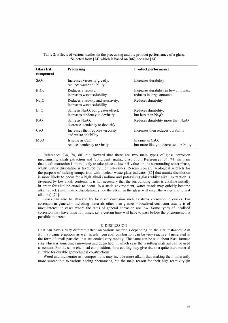
Effects on processing and product performance for a few oxides are compiled in Table 2. Mechanisms for corrosion of glass frequently include a very thin region at the surface which is
depleted with regard to elements that may be soluble in water, and where the depleted layer offers resistance against diffusion of further species from the inside of the glass and to the surrounding water. The depleted layer is perhaps as thin as a few tens of nanometres [79] and at least thinner than 1 micrometre [83]. The depleted layer is frequently covered with a much thicker gel layer of practically insoluble altered material that offers little diffusion resistance. This gel layer may crystallise on further ageing. It appears generally agreed that the diffusion of various cations out of the glass is associated with a diffusion into the glass of oxonium ions (H3O+) [79].
High and low silica glass show different corrosion behaviours [84]. Low silica glass alters to a material called palagonite. Palagonite is depleted with regard to various elements in comparison with the parent glass, and with concomitant uptake of water. High silica glasses alter predominantly by hydration and devitrification, often with little loss of cations [84].
15
Table 2: Effects of various oxides on the processing and the product performance of a glass. Selected from [74] which is based on [86], see also [34].
Glass frit component
Processing Product performance
SiO2 Increases viscosity greatly; reduces waste solubility
Increases durability
B2O3 Reduces viscosity; increases waste solubility
Increases durability in low amounts, reduces in large amounts
Na2O Reduces viscosity and resistivity; increases waste solubility
Reduces durability
Li2O Same as Na2O, but greater effect; increases tendency to devitrify
Reduces durability, but less than Na2O
K2O Same as Na2O; decreases tendency to devitrify
Reduces durability more than Na2O
CaO Increases then reduces viscosity and waste solubility
Increases then reduces durability
MgO Is same as CaO; reduces tendency to vitrify
Is same as CaO, but more likely to decrease durability
References [34, 74, 80] put forward that there are two main types of glass corrosion
mechanisms: alkali extraction and (congruent) matrix dissolution. References [34, 74] maintain that alkali extraction is more likely to take place at low pH-values in the surrounding water phase, whilst matrix dissolution is favoured by high pH-values. Research on archaeological artefacts for the purpose of making comparison with nuclear waste glass indicates [85] that matrix dissolution is more likely to occur for a high alkali (sodium and potassium) glass whilst alkali extraction is favoured by low alkali contents. It is not necessary that the surrounding water is alkaline initially in order for alkaline attack to occur. In a static environment, water attack may quickly become alkali attack (with matrix dissolution, since the alkali in the glass will enter the water and turn it alkaline) [74].
Glass can also be attacked by localised corrosion such as stress corrosion in cracks. For corrosion in general – including materials other than glasses – localised corrosion usually is of most interest in cases where the rates of general corrosion are low. Some types of localised corrosion may have initiation times, i.e. a certain time will have to pass before the phenomenon is possible to detect.
8 DISCUSSION Heat can have a very different effect on various materials depending on the circumstances. Ash from volcanic eruptions as well as ash from coal combustion can be very reactive if generated in the form of small particles that are cooled very rapidly. The same can be said about blast furnace slag which is sometimes atomized and quenched, in which case the resulting material can be used as cement. For the same chemical composition, slow cooling may give rise to a quite inert material suitable for durable geotechnical constructions.
Wood and incinerator ash compositions may include more alkali, thus making them inherently more susceptible to various ageing phenomena, but the main reason for their high reactivity (in

16
addition to the small grain size and quenching similar to the case of coal ash) is the partitioning taking place during the generation of the ash particles.
Melting of ash material to higher temperatures allows for much more favourable compositions to develop in the molten phase and the glass phase associated with it. Such vitrified ash is – in general - similar in corrosion behaviour to nuclear waste glass and vitrified soil material. Such glasses originating from waste material are also – in general – similar in their corrosion behaviour to natural glasses and glasses in vitrified forts, but – in general – different from that of soda and potash types of glasses, i.e. glasses in archaeological artefacts.
The chemical integrity of various waste materials in the long-term is therefore generally very difficult to predict. In practice, access to archaeological and natural analogues is a necessary prerequisite for any such reliable and robust predictions. This is the case for stabilized waste in a repository (e.g. a landfill) as well as for recycled material in a geotechnical construction. Not least is this the case for various vitrified waste forms, e.g. vitrified incinerator ash, vitrified contaminated soil and vitrified fission products from waste from reprocessing of spent nuclear fuel.
9 CONCLUSIONS
The main conclusion in the present paper is that vitrified materials in at least 200 hillforts constitute good analogues for vitrified waste. The compositions vary considerably from site to site and even within one site, and may correspond relatively well to the spans of parameters in the various vitrified wastes. Glasses in vitrified forts compare favourably to archaeological artefacts which are soda and potash based and consequently have a different corrosion behaviour, and may weather too quickly. Natural glasses might be too limited in composition variation and are perhaps also too durable.
No record has been found on the utilisation of glass in vitrified forts as anthropogenic analogues to glass prepared using waste material. The findings in this paper strongly support and suggest that such studies be initiated.
Combustion technology considerations - including an analysis based on the quality of the heat provided - indicate that at least some of the vitrifications of hillforts were carried out with the specific purpose of achieving strong and durable constructions. It also appears likely that people selected rock material that was comparatively easy to fuse. Consequently, it is also possible to identify what processes might have been used. Such information is essential for a fruitful comparison between anthropogenic analogues and modern vitrified wastes.
No record has been found on anyone utilizing quality of heat based analysis in order to find the reasons for the vitrification of the hill forts. It is suggested that tests be carried out based on the results in this paper.
9 ACKNOWLEDGEMENTS
This work was made possible through a grant from Ångpanneföreningen’s Foundation for Research and Development, and this support is hereby gratefully acknowledged. We wish to acknowledge the valuable comments we received from Anna Hinderson and Lennart Gårdman, both affiliated with Vattenfall Research and Development AB. The authors are especially grateful to the editor and the anonymous referees for their helpful suggestions and insightful comments that have improved the clarity and presentation of this paper. We would also like to thank Mrs Elizabeth Cherry at WIT for her enthusiastic support.

17
10 REFERENCES [1] Guiding Principles Concerning International Economic Aspects of Environmental Policies,
Council Recommendation C(72)128, OECD, Paris, 26 May 1972. [2] Brundtland, G., Chairman, Our Common Future (The Brundtland report). World
Commission on environment and Development, Oxford University Press, Oxford, United Kingdom, 1987.
[3] The Swedish Environmental Code. English translation. Ds 2000:61. (In Swedish Miljöbalk, SFS 1998:808).
[4] Lindskog, S. & Sjöblom, R., Implementation of the polluter pays principle - example of planning for decommissioning. Environmental Economics and Investment Assessment III, 3-5 May 2008, Limassol, Cyprus. WIT Transactions on Ecology and the Environment, 131, pp. 235-246, 2010.
[5] Sakai, S. and Hiraoka, M., Municipal solid waste incinerator residue recycling by thermal processes. Waste Management 20, pp. 249-258, 2000.
[6] Ecke H., Sakanakura H., Matsuto T., Tanaka N. & Lagerkvist A., State-of-the-art treatment process for municipal solid waste incineration residues in Japan. Waste Management and Research, 18, pp. 41-51, 2000.
[7] Christensen, T. H., editor, Solid waste technology & management. John Wiley and Sons, 2011.
[8] Disposal of waste. Handbook with general advice to the ordinance (SFS 2001:512) on disposal of waste and to chapter 15 § 34 in the Environmental Code (SFS 1998:808). (In Swedish). Swedish Environmental Protection Agency, 2004.
[9] Sjöblom, R., Tillämpning av avfallsförordningen SFS 2001:1063; Bidrag till kunskapsbasen avseende förbränningsrester. (Implementation of the Swedish ordinance of waste SFS 2001:1063. Contribution to the knowledge base on residues from combustion and incineration, in Swedish). Värmeforsk, Sweden. Miljöriktig användning av askor. Report number 1103, March 2009.
[10] Sjöblom, R., Hydrogen Bond Studies 112. Molecular reorientations in some hydrogen bonded solids. Acta Universitatis Upsaliensis, Abstracts of Uppsala dissertations from the Faculty of Science 350 (1975).
[11] Kresten, P., & Ambrosiani, B., Swedish vitrified forts – a reconnaissance study. Fornvännen, 87, pp. 1–17, 1992.
[12] Kresten, P., Goedicke, C., & Manzano, A., TL - dating of vitrified material. Geochimometria – Journal on Methods and Applications of Absolute Chronology, 22, pp. 9-14, 2003
[13] Ralston I., Celtic fortifications. Tempus Publishing Ltd., 2000. [14] M’Hardy, A.B., On vitrified forts, with results of experiments as to the probable manner in
which their vitrification may have been produced. Proc. Soc. Antiq. Scot. 40, pp. 136–150, 1906.
[15] Kresten, P., The Vitrified forts of Europe: saga, archaeology and geology. In: Pecchio, M. et al. (Eds.), Applied Mineralogy: Developments in Science and Technology, Sao Paolo, pp. 355–357, 2004.
[16] Hewlett, P. C., Lea's chemistry of cement and concrete, 4th edition. Butterworth-Heinemann, 2001.
[17] Hydrauliskt kalkbruk. Produktion och användning i Sverige vid byggande från medeltid till nutid. (Hydraulic lime mortar. Its production and utilisation in Sweden in buildings from the middle ages until the present time, in Swedish but with an extensive summary in English). Chalmers University of Technology and Göteborg University. Göteborg studies in conservation No 20. Printed at the Reproservice AB in Göteborg, Sweden, 2007.

18
[18] MacKie, E.W., The Vitrified Forts of Scotland. In: Harding, D.W. (Ed.), Hillforts, Later Prehistoric Earthworks in Britain and Ireland. Academic Press, London, pp. 205–235, 1976.
[19] Kresten, P., Kero, L., & Chryssler, J., Geology of the vitrified hill-fort Broborg in Uppland, Sweden. Geologiska Föreningen i Stockholm Förhandlingar, 115, pp. 13–24, 1993.
[20] Diaz-Martinez, E., Soares, A.M.M., Kresten, P., & Glazovskya, L., Evidence for wall vitrification at the Late Bronze Age settlement of Passo Alto (Vila Verde de Ficalho, Serpa, Portugal). Rev. Port. Arqueol. 8, pp. 151–161, 2005.
[21] Friend, C.R.L., Charnley, N.R., Clyne, H., & Dye, J., Experimentally produced glass compared with that occurring at The Torr, NW Scotland, UK: vitrification through biotite melting. Journal of Archaeological Science, 35, Issue 12, pp. 3130-3143, December, 2008.
[22] Youngblood, E., Fredriksson, B.J., Kraut, F., & Fredriksson, K., Celtic vitrified forts: implications of a chemical-petrological study of glasses and source rocks. J. Arch. Sci., 5, pp. 99–121, 1978.
[23] Friend, C. R. L., Dye, J., Fowler, & M. B. New field and geochemical evidence from vitrified forts in South Morar and Moidart, NW Scotland: further insight into melting and the process of vitrification. Journal of Archaeological Science, 34, pp. 1685-1701, 2007.
[24] Dobran F., Volcanic processes, mechanisms in material transport. Kluwer academic, 2001. [25] Spear, S. S., Metamorphic phase equilibria and pressure-temperature-time paths.
Mineralogical Society of America. Printed by BookCrafters Inc., 1995. [26] Oleson, J. P. (Editor), The Oxford handbook of engineering and technology in the classical
world. Oxford University Press, 2008. [27] Arrhenius, S., Kemin och det moderna livet. (Chemistry and the modern life, in Swedish).
Hugo Gebers Förlag, Stockholm, 1919. [28] Charcoal. In: Gerhartz, W. (Executive Editor), Ullmann's encyclopedia of industrial
chemistry, 5th Edition, A6. VCH Verlagsgesellschaft mbH, 1986. [29] Oates, J. A. H., Lime and limestone. Wiley-VCH, 1998. [30] Karlebo handbok. Maskinaktiebolaget Karlebo, Stockholm, 1936. [31] Lide, D. R. (Editor), CRC handbook of chemistry and physics. CRC Press, 2003. [32] Amutha Rani, D., Gomez, E., Boccaccini, A. R., Hao, L., Deegan, D. & Cheeseman, C. R.
Plasma treatment of air pollution control residues. Waste Management, 28(7), pp. 1254-62, 2008.
[33] Ecke, H., Sakanakura, H., Matsuto, T., Tanaka, N. & Lagerkvist, A. State-of-the-art treatment processes for municipal solid waste incineration residues in Japan. Waste Management & Research, 18(1) pp. 41-51, 2000.
[34] Chandler, A. J., et al (Editors), Municipal solid waste incineration residues. The International Ash Working Group. Studies in Environmental Science 67. Elsevier, 1997.
[35] Karlfeldt, K., Characterisation and speciation of metals in ash. Thesis for the degree of licentiate of philosophy. Department of Chemical and Biological Engineering and Division of Environmental Inorganic Chemistry, Chalmers University of Technology., Göteborg, Sweden, 2006.
[36] Clarke, L. B. and Sloss, L. L., Trace elements – emissions from coal combustion and gasification. IEACR/49. London, UK, IEA Clean Coal Centre, 111, July, 1992.
[37] Sloss, L. L., Trace elements and fly ash utilisation. IEA Clean Coal Centre, March 2007. [38] Kuo, Y.-M., Huang, K.-L., Wang, C.-T. & Wang, J.-W. Effect of Al2O3 mole fraction and
cooling method on vitrification of an artificial hazardous material. Part 1: Variation of crystalline phases and slag structures. Journal of Hazardous Materials, 169(1-3), 626-34, 2009.

19
[39] Yang, Y., Xiao, Y., Voncken, J. H. L. & Wilson, N. Thermal treatment and vitrification of boiler ash from a municipal solid waste incinerator. Journal of Hazardous Materials, 154(1-3), pp 871-9, 2008.
[40] Lin, K. L., Huang, W. J., Chen, K. C., Chow, J. D. & Chen, H. J. Behaviour of heavy metals immobilized by co-melting treatment of sewage sludge ash and municipal solid waste incinerator fly ash. Waste Management & Research, 27(7) pp 660-7, 2009.
[41] Garcia-Valles, M., Avila, G., Martinez, S., Terradas, R. & Nogues, J. M. Heavy metal-rich wastes sequester in mineral phases through a glass-ceramic process. Chemosphere, 68(10), pp 1946-53, 2007.
[42] Li, C. T., Lee, W. J., Huang, K. L., Fu, S. F. & Lai, Y. C. Vitrification of chromium electroplating sludge. Environmental Science & Technology, 41(8), pp 2950-6, 2007.
[43] Karamanov, A., Aloisi, M. & Pelino, M. Vitrification of copper flotation waste. Journal of Hazardous Materials, 140(1-2), pp333-9, 2007.
[44] Romero, M., Hernández-Crespo, M. S. & Rincón, J. M. Leaching behaviour of a glassy slag and derived glass ceramics from arc plasma vitrification of hospital wastes. Advances in Applied Ceramics: Structural, Functional & Bioceramics, 108(1) pp67-71, 2009.
[45] Sobiecka, E., Cedzynska, K. & Smolinska, B. Vitrification as an alternative method of medical waste stabilization. Fresenius Environmental Bulletin, 19(12A), pp3045-8, 2010.
[46] Stoch, L., Procyk, B. & Stoch, P. Thermochemistry of vitrified waste incineration ashes crystallization. Journal of Thermal Analysis and Calorimetry, 97(1), pp 197-201, 2009.
[47] Basegio, T., Leao, A. P. B., Bernardes, A. M. & Bergmann, C. P. Vitrification: An alternative to minimize environmental impact caused by leather industry wastes. Journal of Hazardous Materials, 165(1-3), pp 604-11, 2009.
[48] Saffarzadeh, A., Shimaoka, T., Motomura, Y. & Watanabe, K. Characterization study of heavy metal-bearing phases in MSW slag. Journal of Hazardous Materials, 164(2-3), pp 829-34, 2009.
[49] Zhao, P., Ni, G. H., Jiang, Y. M., Chen, L. W., Chen, M. Z. & Meng, Y. D. Destruction of inorganic municipal solid waste incinerator fly ash in a DC arc plasma furnace. Journal of Hazardous Materials, 181(1-3), pp 580-5, 2010.
[50] Tu, X., Yu, L., Yan, J. H., Cen, K. F. & Cheron, B. G. Plasma Vitrification of Air Pollution Control Residues From Municipal Solid-Waste Incineration. Ieee Transactions on Plasma Science, 38(12), pp 3319-25, 2010.
[51] Wang, Q., Yan, J. H., Chi, Y., Li, X. D. & Lu, S. Y. Application of thermal plasma to vitrify fly ash from municipal solid waste incinerators. Chemosphere, 78(5), pp 626-302010.
[52] Roether, J. A., Daniel, D. J., Amutha Rani, D., Deegan, D. E., Cheeseman, C. R. & Boccaccini, A. R. Properties of sintered glass-ceramics prepared from plasma vitrified air pollution control residues. Journal of Hazardous Materials, 173(1-3), pp 563-9, 2010.
[53] Zhao, P., Meng, Y. D., Yu, X. Y., Chen, L. W., Jiang, Y. M., Ni, G. H. & Chen, M. Z. Energy Balance in DC Arc Plasma Melting Furnace. Plasma Science & Technology, 11(2), pp 206-10, 2009.
[54] Wang, Q., Yan, J. H., Tu, X., Chi, Y., Li, X. D., Lu, S. Y. & Cen, K. F. Thermal treatment of municipal solid waste incinerator fly ash using DC double arc argon plasma. Fuel, 88(5), pp 955-8, 2009.
[55] Kuo, Y.-M., Tseng, H.-J., Chang, J.-E., Wang, J.-W., Wang, C.-T. & Chen, H.-T. An alternative approach for reusing slags from a plasma vitrification process. Journal of Hazardous Materials, 156(1-3), pp 442-7, 2008.
[56] Kuo, Y. M., Wang, C. T., Tsai, C. H. & Wang, L. C. Chemical and physical properties of plasma slags containing various amorphous volume fractions. Journal of Hazardous Materials, 162(1), pp 469-75, 2009.

20
[57] Cheng, T. W., Huang, M. Z., Tzeng, C. C., Cheng, K. B. & Ueng, T. H. Production of coloured glass-ceramics from incinerator ash using thermal plasma technology. Chemosphere, 68(10), pp 1937-45, 2007.
[58] Gomez, E., Rani, D. A., Cheeseman, C. R., Deegan, D., Wise, M. & Boccaccini, A. R. Thermal plasma technology for the treatment of wastes, pp A critical review. Journal of Hazardous Materials, 161(2-3), pp 614-26, 2009.
[59] Yang, J. K., Xiao, B. & Boccaccini, A. R. Preparation of low melting temperature glass-ceramics from municipal waste incineration fly ash. Fuel, 88(7), pp 1275-80, 2009.
[60] Fruergaard, T., Hyks, J. & Astrup, T. Life-cycle assessment of selected management options for air pollution control residues from waste incineration. Science of The Total Environment, 408(20), pp 4672-80, 2010.
[61] da Silveira, F. Z., Pich, C. T., Angioletto, E. & Bernardin, A. M. Ecotoxicological analysis of glasses obtained from industrial residues using E. coli and S. aureus as bioindicators. Materials Science and Engineering: C, 31(2), pp 276-80, 2011.
[62] Sakai, S.-i. & Hiraoka, M. Municipal solid waste incinerator residue recycling by thermal processes. Waste Management, 20(2-3), pp 249-58, 2000.
[63] Ecke, H., Sakanakura, H., Matsuto, T., Tanaka, N. & Lagerkvist, A. The effect of electric arc vitrification of bottom ash on the mobility and fate of metals. Environmental Science & Technology, 35(7), pp 1531-6, 2001.
[64] Oresek, N., Berk, F., Samec, N. & Zupanic, F. Fly ash immobilization with vitrification. Materiali in Tehnologije, 44(6), pp 373-8, 2010.
[65] Lin, K. L. & Chang, C. T. Leaching characteristics of slag from the melting treatment of municipal solid waste incinerator ash. Journal of Hazardous Materials, 135(1-3), pp 296-302, 2006.
[66] Kuo, Y. M., Wang, J. W. & Tsai, C. H. Encapsulation behaviors of metals in slags containing various amorphous volume fractions. Journal of the Air & Waste Management Association, 57(7), pp 820-7, 2007.
[67] Yang, Y., Xiao, Y., Wilson, N. & Voncken, J. H. L. Thermal behaviour of ESP ash from municipal solid waste incinerators. Journal of Hazardous Materials, 166(1), pp 567-75, 2009.
[68] Kuo, Y. M., Wang, J. W., Chao, H. R., Wang, C. T. & Chang-Chien, G. P. Effect of cooling rate and basicity during vitrification of fly ash Part 2. On the chemical stability and acid resistance of slags. Journal of Hazardous Materials, 152(2), pp 554-62, 2008.
[69] Monteiro, R. C. C., Alendouro, S. J. G., Figueiredo, F. M. L., Ferro, M. C. & Fernandes, M. H. V. Development and properties of a glass made from MSWI bottom ash. Journal of Non-Crystalline Solids, 352(2), pp 130-5, 2006.
[70] Monteiro, R. C. C., Figueiredo, C. F., Alendouro, M. S., Ferro, M. C., Davim, E. J. R. & Fernandes, M. H. V. Characterization of MSWI bottom ashes towards utilization as glass raw material. Waste Management, 28(7), pp 1119-25, 2008.
[71] Ferraris, M., Salvo, M., Ventrella, A., Buzzi, L. & Veglia, M. Use of vitrified MSWI bottom ashes for concrete production. Waste Management, 29(3), pp 1041-7, 2009.
[72] Vasilopoulos, K. C., Tulyaganov, D. U., Agathopoulos, S., Karakassides, A., Ribeiro, M., Ferreira, J. M. F. & Tsipas, D. Vitrification of low silica fly ash: suitability of resulting glass ceramics for architectural or electrical insulator applications. Advances in Applied Ceramics, 108(1), pp 27-32, 2009.
[73] Bassani, M., Santagata, E., Baglieri, O., Ferraris, M., Salvo, M. & Ventrella, A. Use of vitrified bottom ashes of municipal solid waste incinerators in bituminous mixtures in substitution of natural sands. Advances in Applied Ceramics, 108(1), pp 33-43, 2009.

21
[74] Handbook. Vitrification technologies for treatment of hazardous and radioactive waste. U. S. Environmental Protection Agency, EPS/625/R-92/002, May 1992.
[75] Campbell, B., Thompson, L. and Finucane, K., Geomelt vitrification: Status of recent developments and project results. ICEM’05: the 10th International Conference on Environmental Remediation and Radioactive Waste Management. September 4-8, Glasgow, Scotland.
[76] Luey, J., Roberts, J. S. and Timmerman, C. L., Implementation of in situ vitrification for contaminated soils. Presented at the American Institute of Chemical Engineers National Summer Meeting, August 15-18, 1993, Seattle Washington, USA.
[77] Thompson, L., Huddleston, G., Reichhart, D., Jones, J., Springer, M. and Campbell. B., Results from the non-traditional (sub-surface) in situ vitrification demonstration for mixed waste applications at the los Alamos National Laboratory. WM’01 Conference, February 25-March 1, 2001, Tucson, Arizona, USA.
[78] Ojovan, M. I. and Lee, W. E., An introduction to nuclear waste immobilisation. Elsevier Ltd., 2005.
[79] White, W. B., Theory of corrosion of glass and ceramics. In Clark, D. E. and Zoitos B. K., Corrosion of glass, ceramics and ceramic superconductors. Principles, testing, characterization and applications. Noyes Publications, 1992.
[80] Grambow, B., Geochemical approach to glass dissolution. In Clark, D. E. and Zoitos B. K., Corrosion of glass, ceramics and ceramic superconductors. Principles, testing, characterization and applications. Noyes Publications, 1992. ISBN 0-8155-1283-X.
[81] H. T. Scheffers chemiske föreläsningar. (Mr H. T. Scheffer’s chemical lectures, in Swedish). Lectures held at around 1750. Notes made by his student Alströmer, comments added later by Torbern Bergman. Printed at Joh. Edman, Royal Academy, 1775. Printing financed by M. Swederi.
[82] Le Bourhis, E., Glass. Mechanics and technology. Wiley-VCH Verlag GmbH & Co., 2008. [83] Jantzen, C. M., Thermodynamic approach to glass corrosion. In Clark, D. E. and Zoitos B.
K., Corrosion of glass, ceramics and ceramic superconductors. Principles, testing, characterization and applications. Noyes Publications, 1992.
[84] Jercinovic, M. J. and Ewing, R. C., Corrosion of geological and archaeological glasses. In Clark, D. E. and Zoitos B. K., Corrosion of glass, ceramics and ceramic superconductors. Principles, testing, characterization and applications. Noyes Publications, 1992.
[85] McLoughlin, S. D., Hyatt, N. C., Hand, R. J. and Lee, W. E., Corrosion of archaeological model glasses after 32 years of burial at Ballidon. Mat. Res. Soc. Symp. Proc. 932, 2006.
[86] Plodinec, M.J., Wicks, G. G. and Bibler, N. E., An Assessment of Savannah River Borosilicate Glass in the Repository Environment. DP-1629, Savannah River Laboratory, Aiken, South Carolina, 1982.