Embed Size (px)
Citation preview

<www.excelunusual.com> 1
Longitudinal Aircraft Dynamics #9– finalizing the dynamics –preliminary validation by George Lungu
- This section continues with the dynamics formulas governing our 2D plane.
- Copy the last worksheet and
name the new one “Longitudinal_
Stability_Model_5”
- There are three buttons, the
“Reset”, the “Run_Pause” and the
“CG_visibility” buttons. Make sure
to reassign the right macros to
Worksheet lever calculation formulas:
)_cos()_sin(
)_sin()_cos(
)_cos()_sin(
)_sin()_cos(
planebilizerHeight_staplaneilizerChord_stab4
3elageLength_fusilizer_yLever_stab
planebilizerHeight_staplaneilizerChord_stab4
3elageLength_fusilizer_xLever_stab
planegHeight_winplane4
Chord_wing
100
vity)Center_Gradge_wing(Leading_eelageLength_fus_yLever_wing
planegHeight_winplane4
Chord_wing
100
vity)Center_Gradge_wing(Leading_eelageLength_fus_xLever_wing
them, macros belonging to the current worksheet. By default, the custom buttons (created by the user
from a macro assigned shape) keep the macros from the original worksheet assigned to them.
Implementation:
- O80: “=(Length_fuselage*(Leading_edge_wing-Center_gravity)/100
+Chord_wing/4)*COS(RADIANS(J52))+Height_wing*SIN(RADIANS(J52))”
- O81: “=-(Length_fuselage*(Leading_edge_wing-Center_gravity)/100
+Chord_wing/4)*SIN(RADIANS(J52))+Height_wing*COS(RADIANS(J52))”
- O82: “=(Length_fuselage-3*Chord_stabilizer/4)*COS(RADIANS(J52))
+Height_horizontal_stabilizer*SIN(RADIANS(J52))”
- O83: “=-(Length_fuselage-3*Chord_stabilizer/4)*SIN(RADIANS(J52))
+Height_horizontal_stabilizer*COS(RADIANS(J52))”

<www.excelunusual.com> 2
The force generated moments:
-Using the Cartesian formula to the right (from the
previous section) we can identify eight moment
components generated by the lift and the drag forces.
- All the forces and movements being in the x-y plane the moments will have z-components exclusively.
We can therefore later add the moment effects algebraically.
- Let’s group the moment components by the causing force:
Implementation:
- R67: “=-O80*O68+O81*O67“
- R68: “=-O80*O72+O81*O71“
- R69: “=-O82*O70+O83*O69“
- R70: “=-O82*O74+O83*O73“
In aerodynamics, momenta that have the tendency to raise the nose of the airplane are considered
positive and momenta which have the tendency to lower the nose of the airplane are negative. Pay
attention to signs, I messed it up at first and after seeing weird model behavior I had to come back and
fix it!!!
yOPxOPO FxxFyyM
xstabilizerystabilizerystabilizerxstabilizerdragstabilizer
xstabilizerystabilizerystabilizerxstabilizerliftstabilizer
xwingywingywingxwingdragwing
xwingywingywingxwingliftwing
DragLeverDragLeverMoment
LiftLeverLiftLeverMoment
DragLeverDragLeverMoment
LiftLeverLiftLeverMoment
_____
_____
_____
_____
<www.excelunusual.com> 3
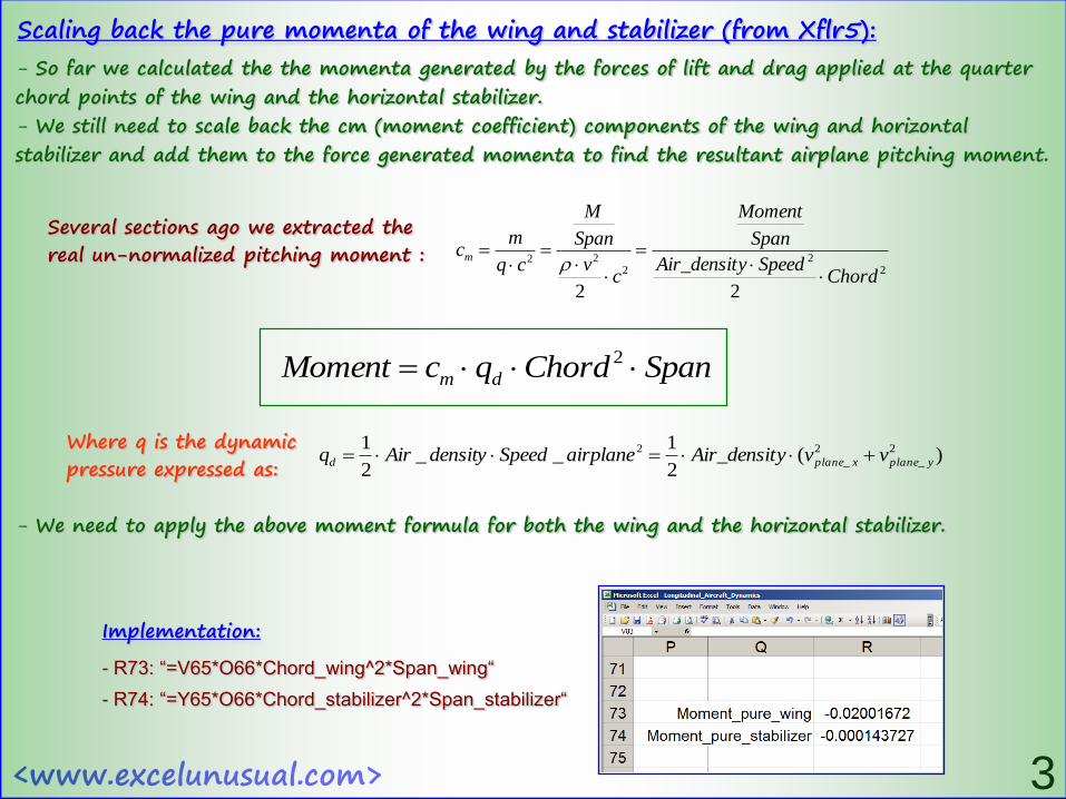
Scaling back the pure momenta of the wing and stabilizer (from Xflr5):
- So far we calculated the the momenta generated by the forces of lift and drag applied at the quarter
chord points of the wing and the horizontal stabilizer.
- We still need to scale back the cm (moment coefficient) components of the wing and horizontal
stabilizer and add them to the force generated momenta to find the resultant airplane pitching moment.
Several sections ago we extracted the real un-normalized pitching moment :
22
222
22Chord
SpeedyAir_densit
Span
Moment
cv
Span
M
cq
mcm
SpanChordqcMoment dm 2
)(2
1__
2
1 2
_
2
_
2
yplanexplaned vvyAir_densitairplaneSpeeddensityAirq Where q is the dynamic pressure expressed as:
- We need to apply the above moment formula for both the wing and the horizontal stabilizer.
Implementation:
- R73: “=V65*O66*Chord_wing^2*Span_wing“
- R74: “=Y65*O66*Chord_stabilizer^2*Span_stabilizer“
<www.excelunusual.com> 4
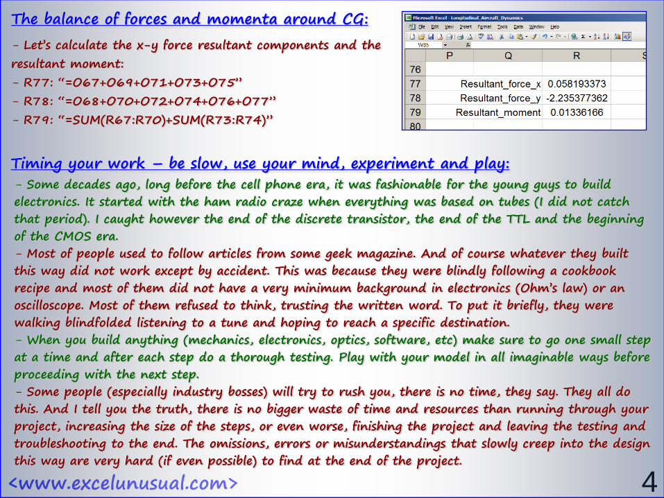
- Let’s calculate the x-y force resultant components and the
resultant moment:
- R77: “=O67+O69+O71+O73+O75”
- R78: “=O68+O70+O72+O74+O76+O77”
- R79: “=SUM(R67:R70)+SUM(R73:R74)”
The balance of forces and momenta around CG:
- Some decades ago, long before the cell phone era, it was fashionable for the young guys to build electronics. It started with the ham radio craze when everything was based on tubes (I did not catch that period). I caught however the end of the discrete transistor, the end of the TTL and the beginning of the CMOS era.- Most of people used to follow articles from some geek magazine. And of course whatever they built this way did not work except by accident. This was because they were blindly following a cookbook recipe and most of them did not have a very minimum background in electronics (Ohm’s law) or an oscilloscope. Most of them refused to think, trusting the written word. To put it briefly, they were walking blindfolded listening to a tune and hoping to reach a specific destination.- When you build anything (mechanics, electronics, optics, software, etc) make sure to go one small step at a time and after each step do a thorough testing. Play with your model in all imaginable ways before proceeding with the next step. - Some people (especially industry bosses) will try to rush you, there is no time, they say. They all do this. And I tell you the truth, there is no bigger waste of time and resources than running through your project, increasing the size of the steps, or even worse, finishing the project and leaving the testing and troubleshooting to the end. The omissions, errors or misunderstandings that slowly creep into the design this way are very hard (if even possible) to find at the end of the project.
Timing your work – be slow, use your mind, experiment and play:
<www.excelunusual.com> 5
- During building of any of my models I spend most of the time at any stage playing with the model
and thinking. Not reading or coding, but playing with parameters, changing angles of perspective and
in general having fun with the model. Each new step follows after the “fun” from the previous step
starts to “die out”.
- The tutorials are written in a linear fashion and they miss that spirit. You need to be aware of this
and balance the content here with a lot of your own experimentation. Don’t trust anything you read
unless it passes your own experimental tests.
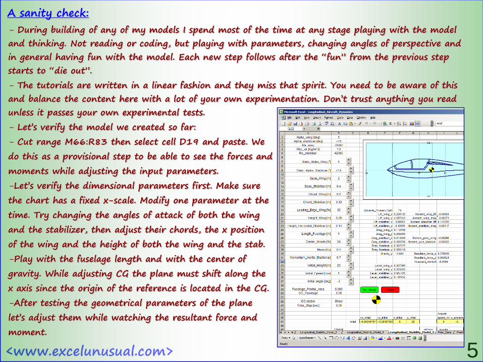
- Let’s verify the model we created so far:
- Cut range M66:R83 then select cell D19 and paste. We
do this as a provisional step to be able to see the forces and
moments while adjusting the input parameters.
-Let’s verify the dimensional parameters first. Make sure
the chart has a fixed x-scale. Modify one parameter at the
time. Try changing the angles of attack of both the wing
and the stabilizer, then adjust their chords, the x position
of the wing and the height of both the wing and the stab.
-Play with the fuselage length and with the center of
gravity. While adjusting CG the plane must shift along the
x axis since the origin of the reference is located in the CG.
-After testing the geometrical parameters of the plane
let’s adjust them while watching the resultant force and
moment.
A sanity check:

<www.excelunusual.com> 6To be continued…
- First, be aware that the wing incidence of a normal plane is around +5 degrees and the incidence of the horizontal stabilizer is slightly negative (-1 or -2 degrees) . Set that, then set the initial speed to 5 m/s and initial launch angle to 0 degrees and hit “Reset”. You must now see forces and momenta for plane moving horizontally at a rate of 5 m/s. Later you will experiment with the speed values.
- Now you can adjust the angle of attack and see an proportional variation of the lift. If you increase the main wing angle of attack past 7-10o you might start to see a drop in lift (stall).
- Play with the position of the center of gravity now. Notice that as you bring the CG forward the momentum becomes negative and increases in absolute value. Exactly the opposite must happen as you move the CG backwards. Bring it around the leading edge and start adjusting the angle of attack of the horizontal stabilizer.
- You can see that you can now greatly change the overall moment on the plane between negative and positive values. The negative values are obtained by setting higher positive angles of attack on the horizontal stabilizer. Similarly the larger the negative angle of attack of the stabilizer is the larger the positive resultant moment on the plane will be. Also move the CG a bit forward and try to cancel the higher absolute value negative moment by giving the stabilizer an increased absolute value negative angle of attack. Move it even more now, until you
cannot balance it anymore with the stabilizer. Increase
the chord or/and the span of the stabilizer and see
how you can now balance much more moment change.
- Play a lot with span and chord values of both the
wing and the horizontal stabilizer and see how all
the forces and moments are affected. Adjust the
length of the plane and check for the efficacy of the
horizontal stabilizer. Be creative.
Atlantica - www.wingco.com