Embed Size (px)
Citation preview
MAE 5930, Rocket Systems Design MAE 5930, Rocket Systems Design
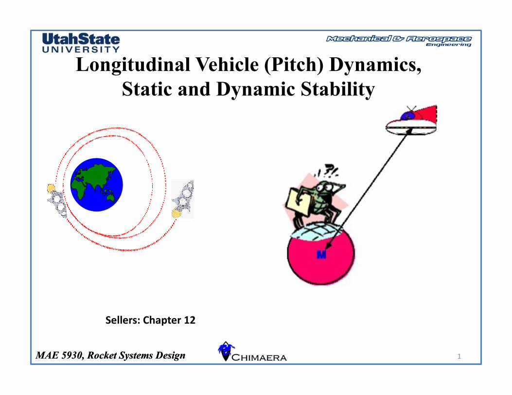
Longitudinal Vehicle (Pitch) Dynamics, Static and Dynamic Stability
Sellers: Chapter 12
1
MAE 5930, Rocket Systems Design
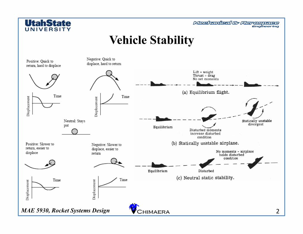
Vehicle Stability
2
MAE 5930, Rocket Systems Design
Vehicle Stability (2)
3
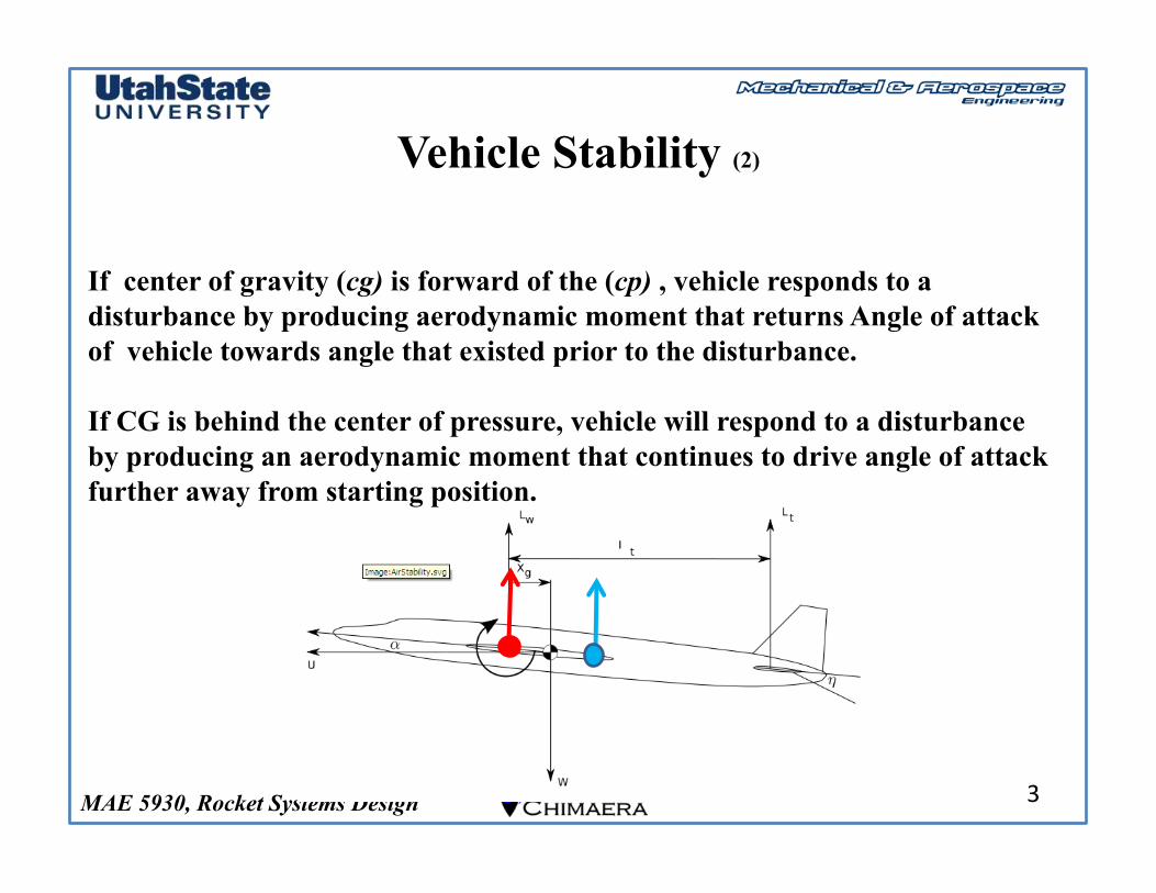
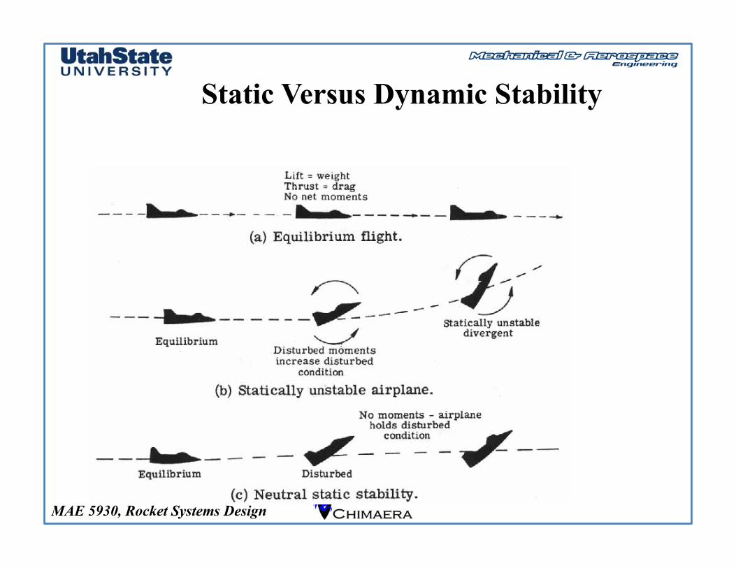
If center of gravity (cg) is forward of the (cp) , vehicle responds to a disturbance by producing aerodynamic moment that returns Angle of attack of vehicle towards angle that existed prior to the disturbance.
If CG is behind the center of pressure, vehicle will respond to a disturbance by producing an aerodynamic moment that continues to drive angle of attack further away from starting position.
MAE 5930, Rocket Systems Design
Center of Pressure
4
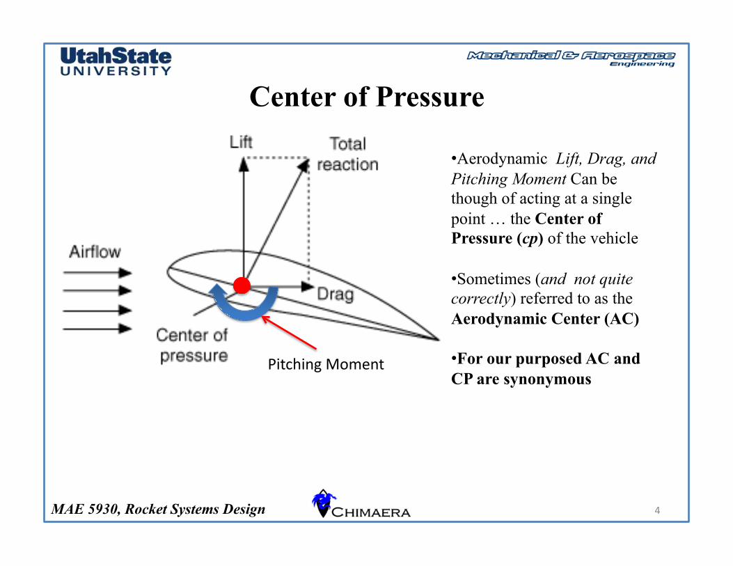
Pitching Moment
• Aerodynamic Lift, Drag, and Pitching Moment Can be though of acting at a single point … the Center of Pressure (cp) of the vehicle
• Sometimes (and not quite correctly) referred to as the Aerodynamic Center (AC)
• For our purposed AC and CP are synonymous
MAE 5930, Rocket Systems Design
Vehicle Stability, Rocket Flight Example
5
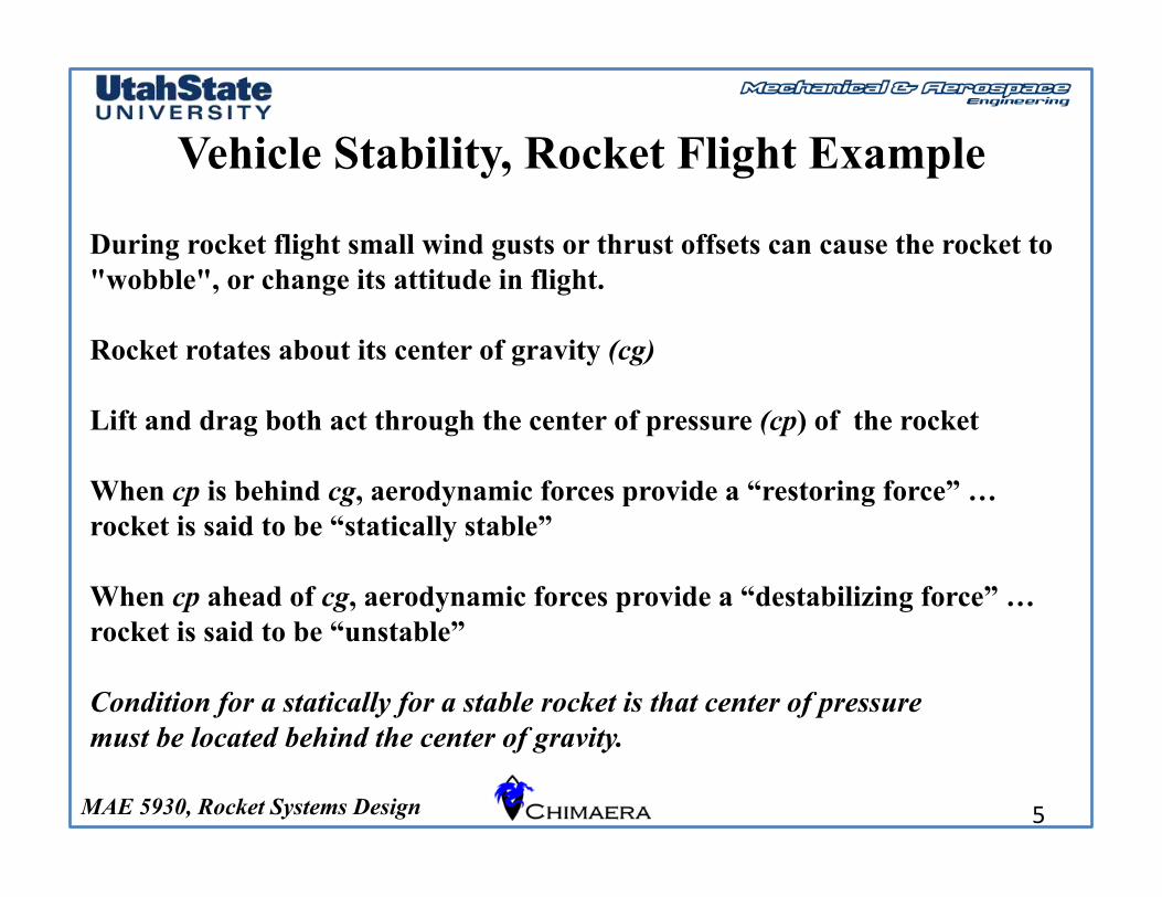
During rocket flight small wind gusts or thrust offsets can cause the rocket to "wobble", or change its attitude in flight.
Rocket rotates about its center of gravity (cg)
Lift and drag both act through the center of pressure (cp) of the rocket
When cp is behind cg, aerodynamic forces provide a “restoring force” … rocket is said to be “statically stable”
When cp ahead of cg, aerodynamic forces provide a “destabilizing force” … rocket is said to be “unstable”
Condition for a statically for a stable rocket is that center of pressure must be located behind the center of gravity.
MAE 5930, Rocket Systems Design
Vehicle Stability, Rocket Flight Example (2)
6
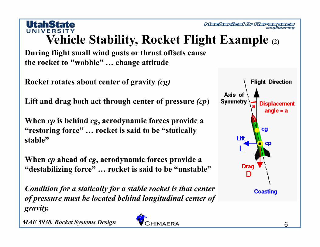
During flight small wind gusts or thrust offsets cause the rocket to "wobble” … change attitude
Rocket rotates about center of gravity (cg)
Lift and drag both act through center of pressure (cp)
When cp is behind cg, aerodynamic forces provide a “restoring force” … rocket is said to be “statically stable”
When cp ahead of cg, aerodynamic forces provide a “destabilizing force” … rocket is said to be “unstable”
Condition for a statically for a stable rocket is that center of pressure must be located behind longitudinal center of gravity.
MAE 5930, Rocket Systems Design
Vehicle Stability, Rocket Flight Example (3)
7
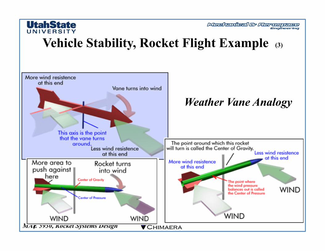
Weather Vane Analogy
MAE 5930, Rocket Systems Design
Vehicle Stability, Rocket Flight Example (4)
8
MAE 5930, Rocket Systems Design
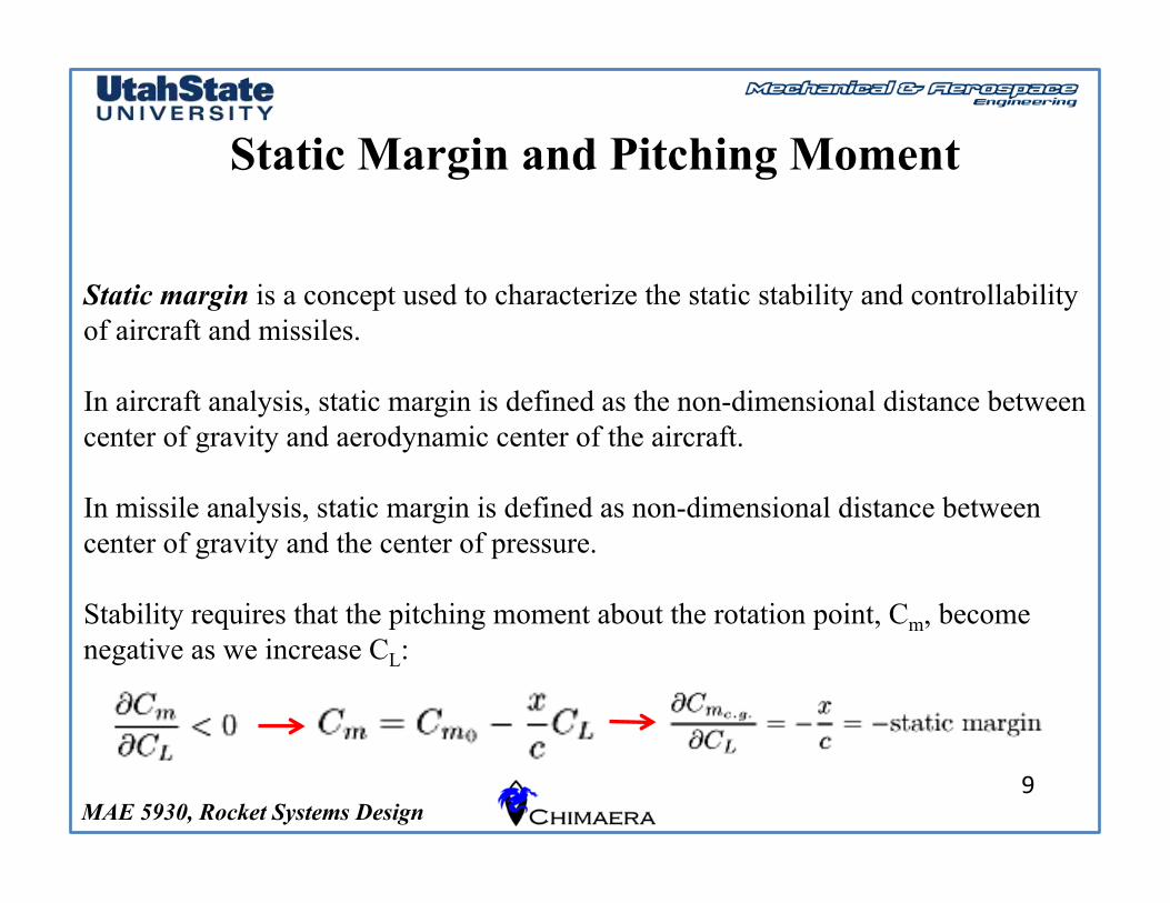
Static Margin and Pitching Moment
9
Static margin is a concept used to characterize the static stability and controllability of aircraft and missiles.
In aircraft analysis, static margin is defined as the non-dimensional distance between center of gravity and aerodynamic center of the aircraft.
In missile analysis, static margin is defined as non-dimensional distance between center of gravity and the center of pressure.
Stability requires that the pitching moment about the rotation point, Cm, become negative as we increase CL:
MAE 5930, Rocket Systems Design
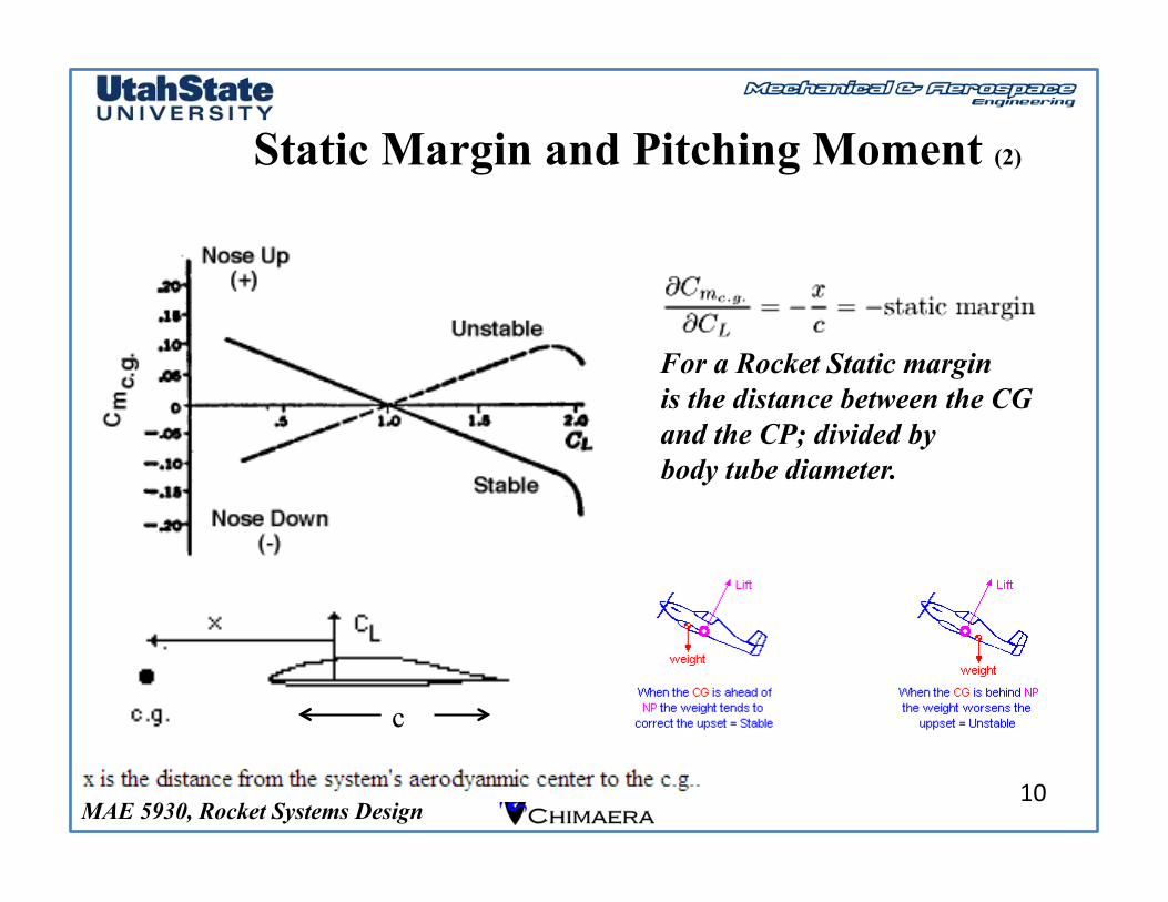
Static Margin and Pitching Moment (2)
10
For a Rocket Static margin is the distance between the CG and the CP; divided by body tube diameter.
c
MAE 5930, Rocket Systems Design
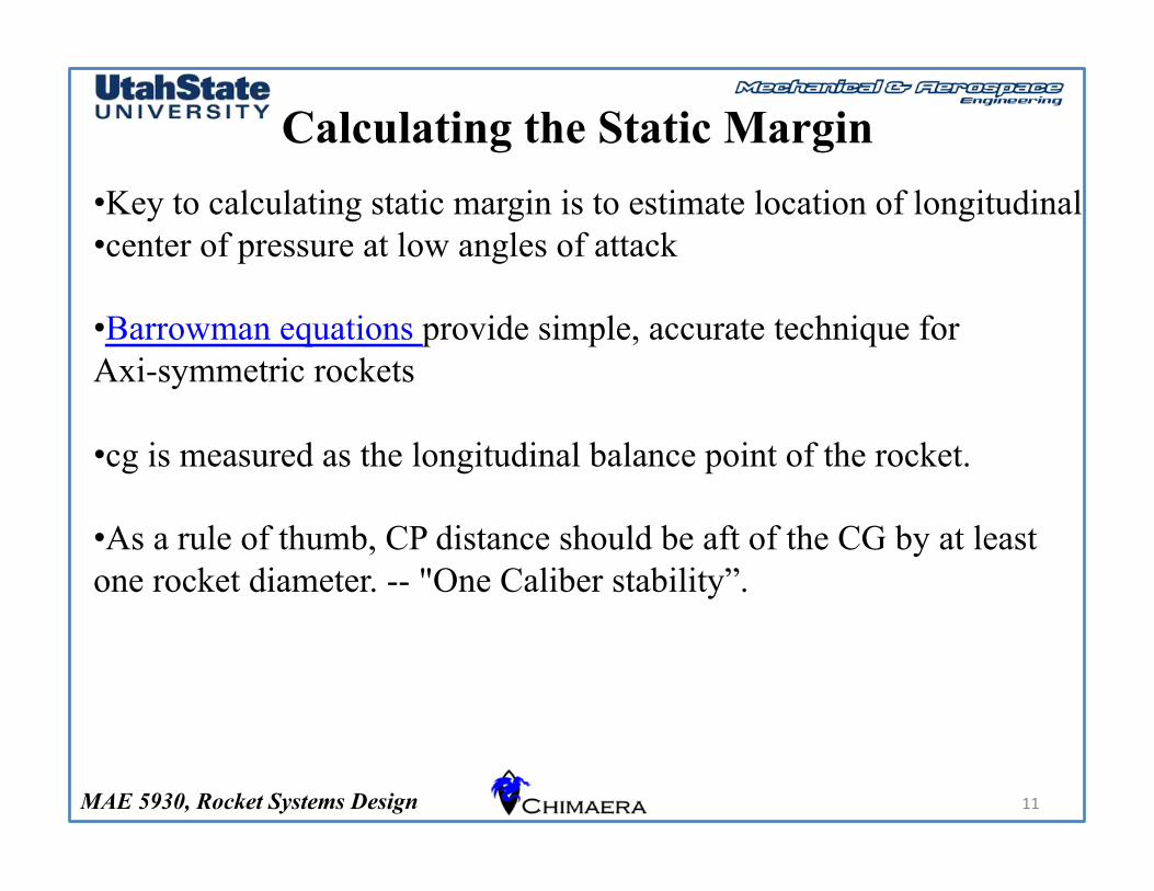
Calculating the Static Margin
11
• Key to calculating static margin is to estimate location of longitudinal • center of pressure at low angles of attack
• Barrowman equations provide simple, accurate technique for Axi-symmetric rockets
• cg is measured as the longitudinal balance point of the rocket.
• As a rule of thumb, CP distance should be aft of the CG by at least one rocket diameter. -- "One Caliber stability”.
MAE 5930, Rocket Systems Design
Calculating the Static Margin (2)
12
MAE 5930, Rocket Systems Design
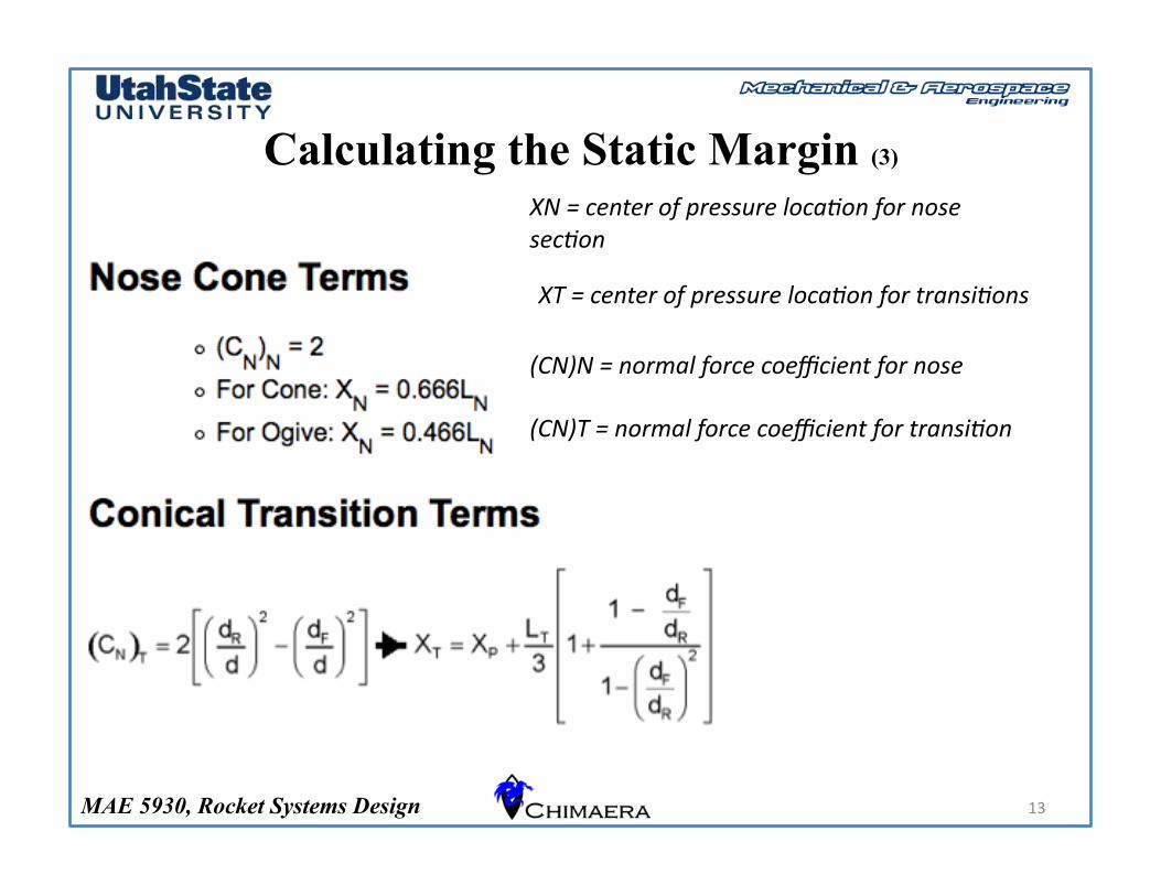
Calculating the Static Margin (3)
13
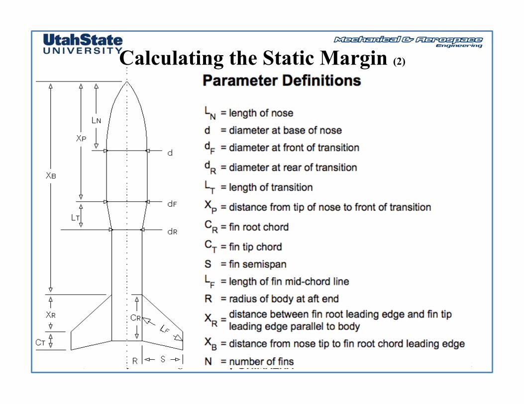
(CN)N = normal force coefficient for nose
(CN)T = normal force coefficient for transi5on
XN = center of pressure loca5on for nose sec5on
XT = center of pressure loca5on for transi5ons
MAE 5930, Rocket Systems Design
Calculating the Static Margin (4)
14
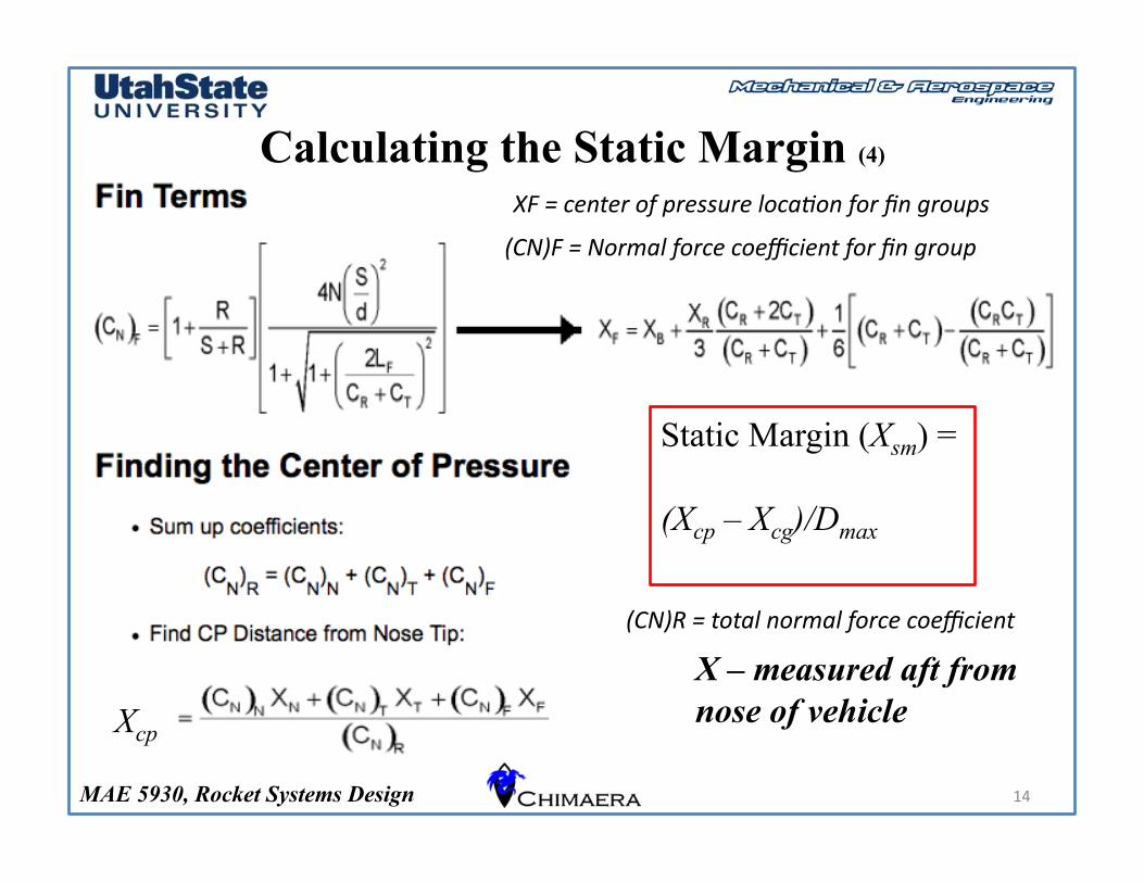
Static Margin (Xsm) =
(Xcp – Xcg)/Dmax
Xcp
X – measured aft from nose of vehicle
(CN)F = Normal force coefficient for fin group
(CN)R = total normal force coefficient
XF = center of pressure loca5on for fin groups
MAE 5930, Rocket Systems Design
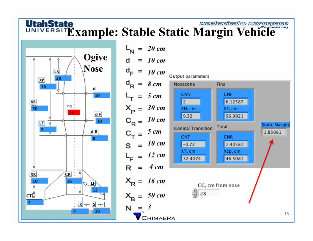
Example: Stable Static Margin Vehicle
15
20 cm 10 cm 10 cm 8 cm 5 cm 30 cm 10 cm 5 cm 10 cm 12 cm 4 cm
16 cm
50 cm 3
Ogive Nose
MAE 5930, Rocket Systems Design
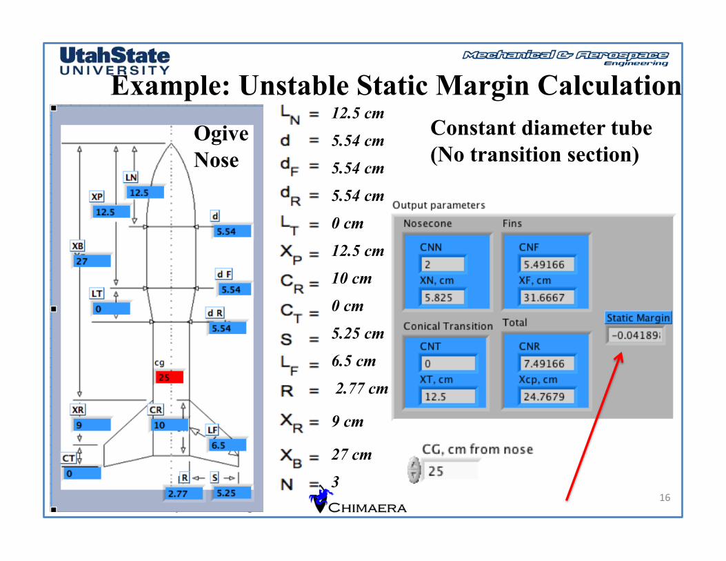
Example: Unstable Static Margin Calculation
16
12.5 cm 5.54 cm 5.54 cm 5.54 cm 0 cm 12.5 cm 10 cm 0 cm 5.25 cm 6.5 cm 2.77 cm
9 cm
27 cm 3
Ogive Nose
Constant diameter tube (No transition section)
MAE 5930, Rocket Systems Design
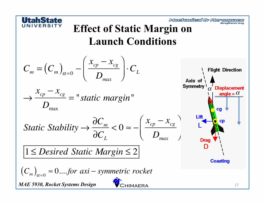
Effect of Static Margin on Launch Conditions
17
Cm = Cm( )α =0 −xcp − xcgDmax
⎛⎝⎜
⎞⎠⎟⋅CL
→xcp − xcgDmax
= "static margin"
Static Stability→ ∂Cm
∂CL
< 0 ≈ −xcp − xcgDmax
⎛⎝⎜
⎞⎠⎟
1 ≤ Desired Static Margin ≤ 2
Cm( )α =0 ≈ 0.... for axi − symmetric rocket
αα
MAE 5930, Rocket Systems Design
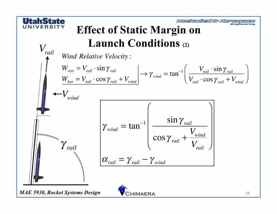
Effect of Static Margin on Launch Conditions (2)
18
Vrail
Vwind
γ rail
Wind Relative Velocity :Wvert = Vrail ⋅ sinγ rail
Whor = Vrail ⋅ cosγ rail +Vwind→γ wind = tan−1 Vrail ⋅ sinγ rail
Vrail ⋅ cosγ rail +Vwind
⎛⎝⎜
⎞⎠⎟
γ wind = tan−1 sinγ rail
cosγ rail +VwindVrail
⎛
⎝
⎜⎜⎜
⎞
⎠
⎟⎟⎟
α rail = γ rail − γ wind
MAE 5930, Rocket Systems Design
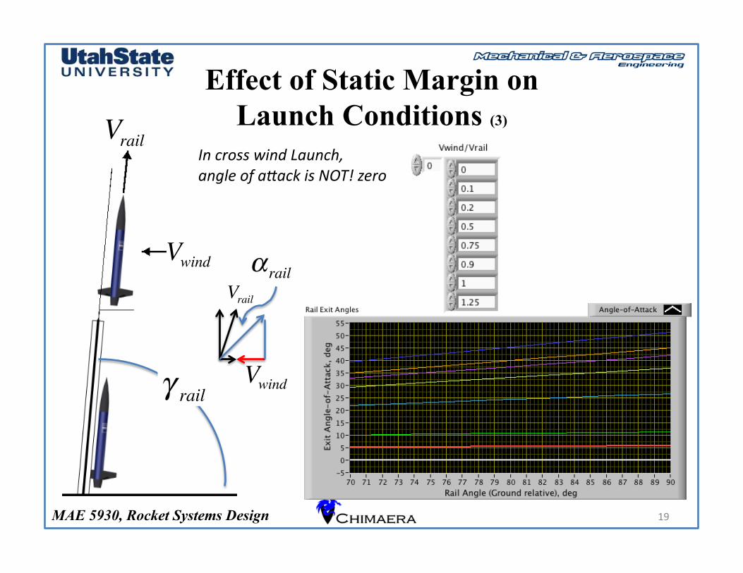
Effect of Static Margin on Launch Conditions (3)
19
Vrail
Vwind
γ rail
α rail
Vwind
Vrail
In cross wind Launch, angle of aCack is NOT! zero
MAE 5930, Rocket Systems Design
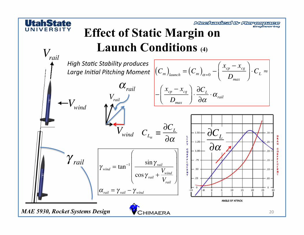
Effect of Static Margin on Launch Conditions (4)
20
Vrail
Vwind
γ rail γ wind = tan−1 sinγ rail
cosγ rail +VwindVrail
⎛
⎝
⎜⎜⎜
⎞
⎠
⎟⎟⎟
α rail = γ rail − γ wind
α rail
Vwind
Vrail
High Sta5c Stability produces Large Ini5al Pitching Moment Cm( )launch = Cm( )α =0 −
xcp − xcgDmax
⎛⎝⎜
⎞⎠⎟⋅CL ≈
−xcp − xcgDmax
⎛⎝⎜
⎞⎠⎟⋅∂CL
∂α⋅α rail
∂CL
∂αCLα
≡∂CL
∂α
MAE 5930, Rocket Systems Design
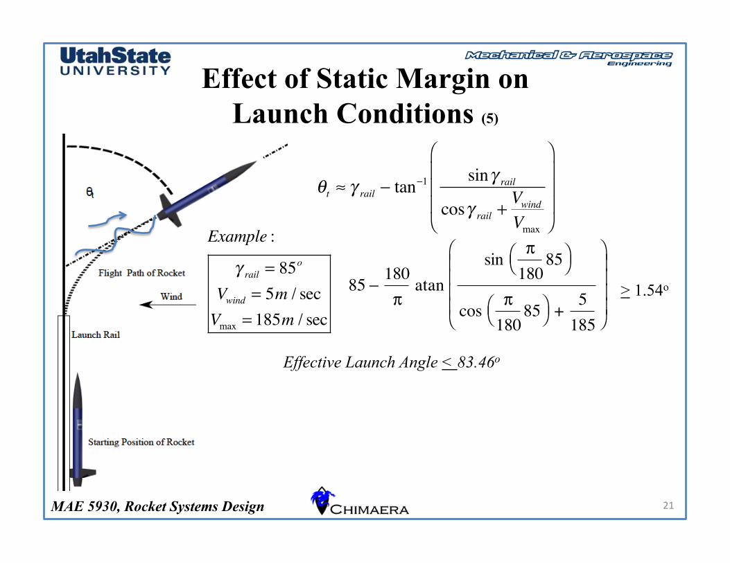
Effect of Static Margin on Launch Conditions (5)
21
θt ≈ γ rail − tan−1 sinγ rail
cosγ rail +VwindVmax
⎛
⎝
⎜⎜⎜
⎞
⎠
⎟⎟⎟
85 180π
π180
85⎝ ⎠⎛ ⎞sin
π180
85⎝ ⎠⎛ ⎞cos 5
185+⎝ ⎠
⎜ ⎟⎜ ⎟⎜ ⎟⎜ ⎟⎛ ⎞
atan−
Example :
γ rail = 85o
Vwind = 5m / secVmax = 185m / sec
> 1.54o
Effective Launch Angle < 83.46o
MAE 5930, Rocket Systems Design
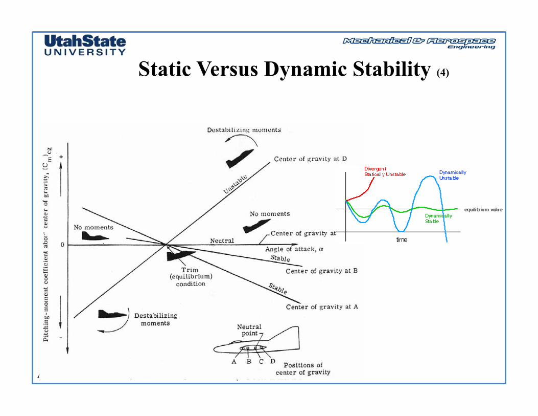
Static Versus Dynamic Stability
MAE 5930, Rocket Systems Design
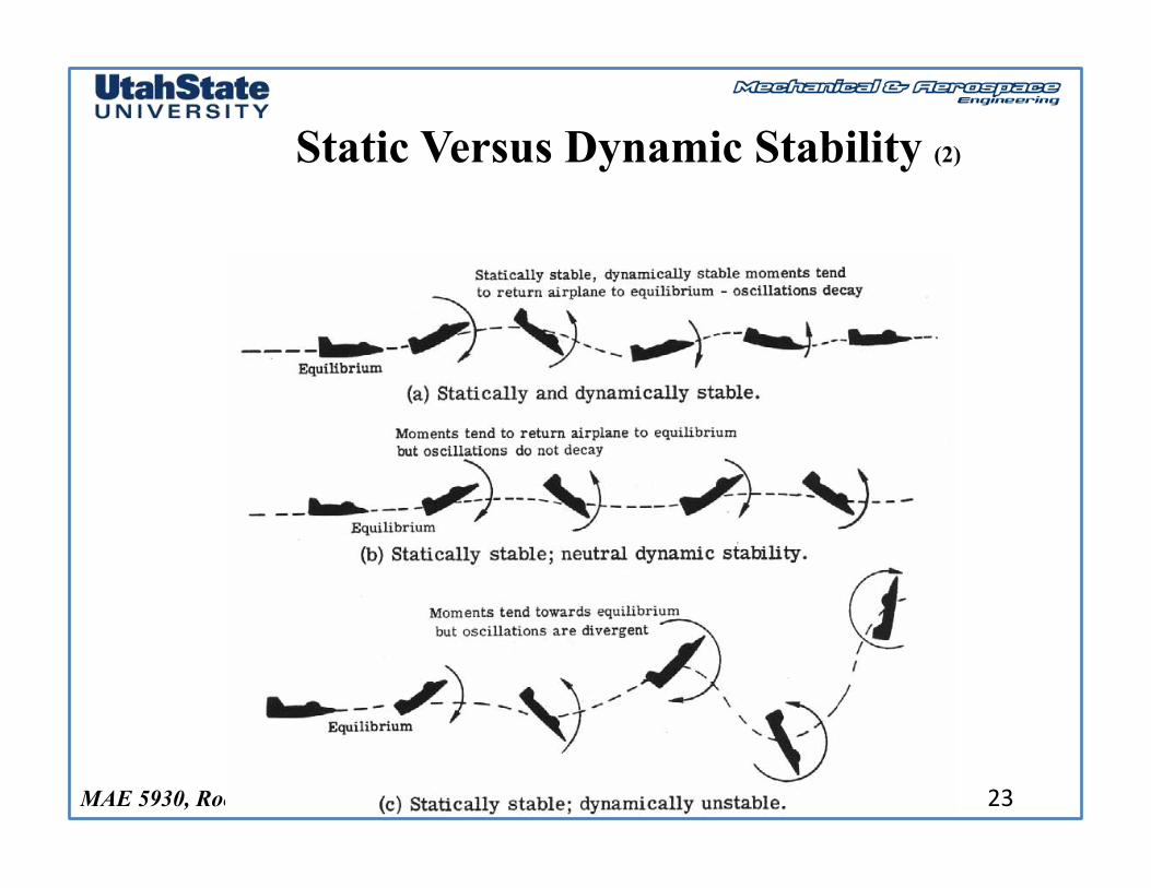
Static Versus Dynamic Stability (2)
23
MAE 5930, Rocket Systems Design
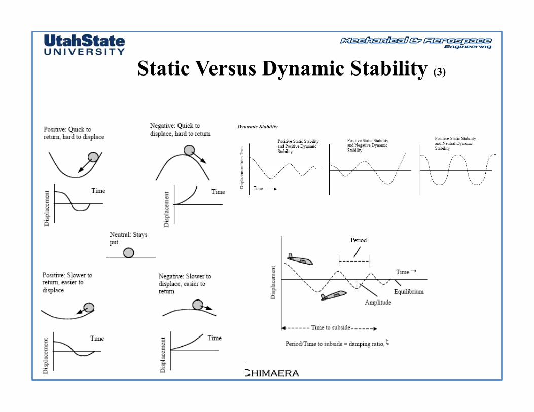
Static Versus Dynamic Stability (3)
24
MAE 5930, Rocket Systems Design
Static Versus Dynamic Stability (4)
25
MAE 5930, Rocket Systems Design
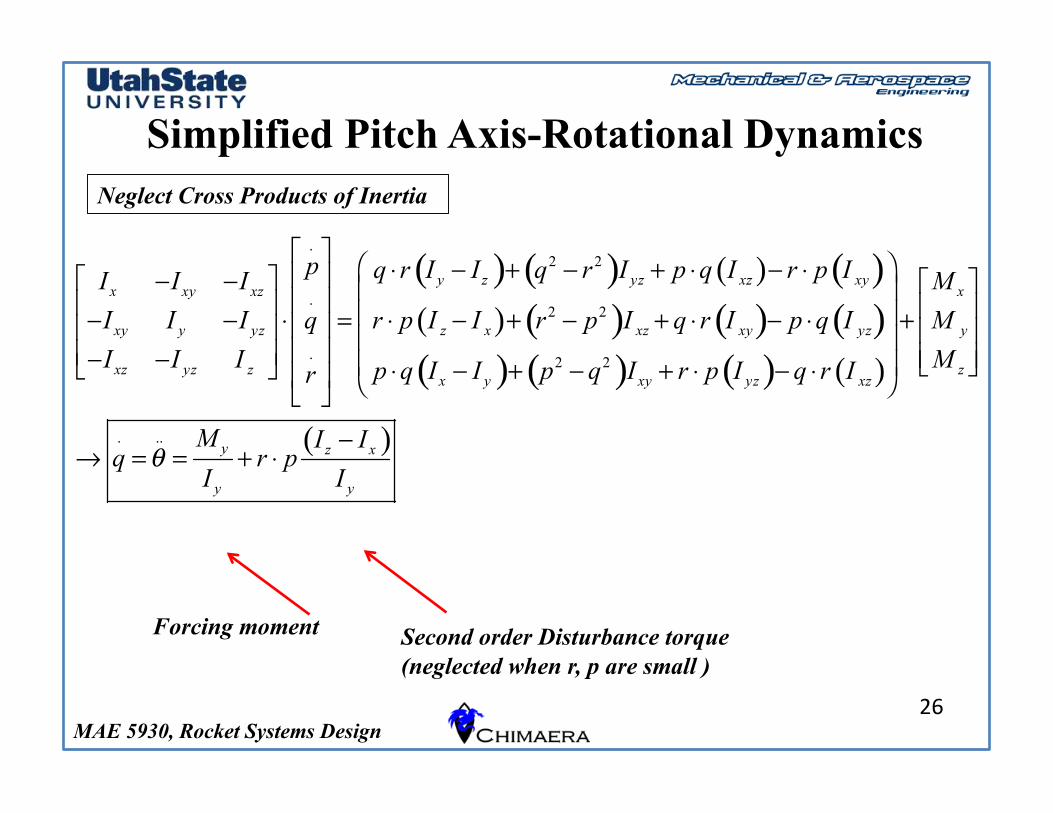
Simplified Pitch Axis-Rotational Dynamics
26
Forcing moment Second order Disturbance torque (neglected when r, p are small )
Neglect Cross Products of Inertia
MAE 5930, Rocket Systems Design
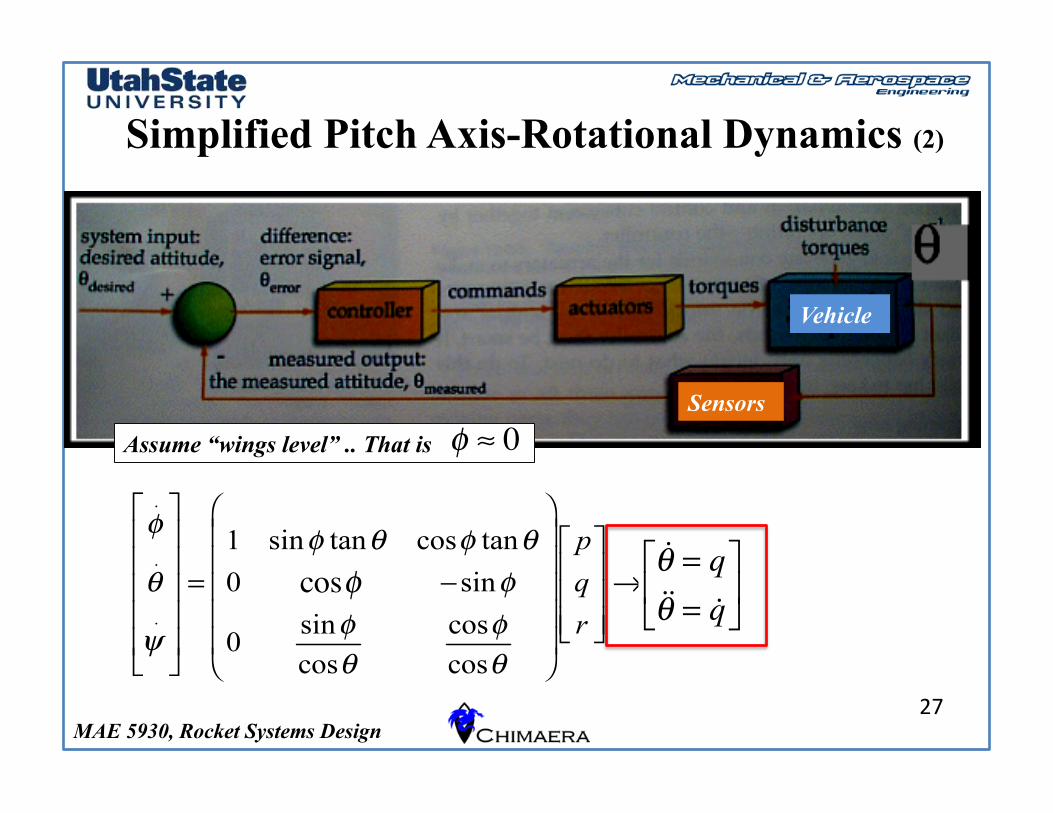
Simplified Pitch Axis-Rotational Dynamics (2)
27
Assume “wings level” .. That is
Vehicle
Sensors ! " 0
cos!
!! = q!!! = !q"
#$
%
&'
MAE 5930, Rocket Systems Design
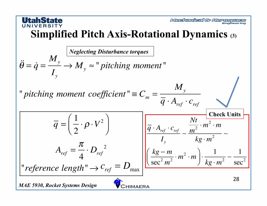
Simplified Pitch Axis-Rotational Dynamics (3)
28
!!! = !q =My
Iy" My # " pitching moment"
" pitching moment coefficient" $ Cm =My
q % Aref % cref
q =12% & %V 2'
()*+,
Aref =-4%Dref
2
"reference length"" cref # Lrocket
Neglecting Disturbance torques
q ! Aref ! crefIy
!
Ntm2 !m
2 !m
kg !m2 !
kg " msec2 m2 !m
2 !m#$%
&'(!
1kg !m2 !
1sec2
Check Units
cref = Dmax
MAE 5930, Rocket Systems Design
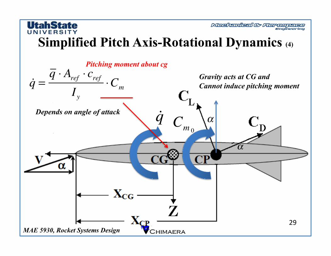
Simplified Pitch Axis-Rotational Dynamics (4)
29
!q Cm 0!
!
Gravity acts at CG and Cannot induce pitching moment
Depends on angle of attack !q =
q ! Aref ! crefIy
!Cm
Pitching moment about cg
MAE 5930, Rocket Systems Design
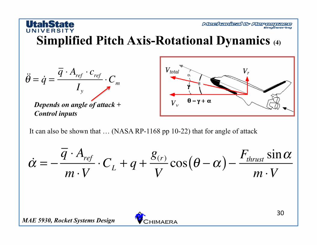
Simplified Pitch Axis-Rotational Dynamics (4)
30
Depends on angle of attack + Control inputs
It can also be shown that … (NASA RP-1168 pp 10-22) that for angle of attack
!! = "
q # Arefm #V
#CL + q +g(r )Vcos $ "!( ) " Fthrust sin!
m #V
!!! = !q =q " Aref " cref
Iy"Cm
MAE 5930, Rocket Systems Design
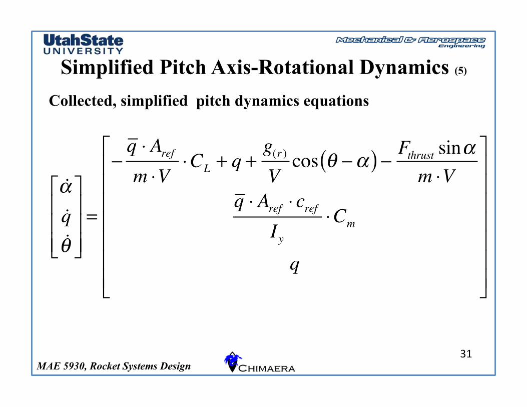
Simplified Pitch Axis-Rotational Dynamics (5)
31
Collected, simplified pitch dynamics equations
!!!q!"
#
$
%%%
&
'
(((=
)q * Arefm *V
*CL + q +g(r )Vcos " )!( ) ) Fthrust sin!
m *Vq * Aref * cref
Iy*Cm
q
#
$
%%%%%%%
&
'
(((((((
MAE 5930, Rocket Systems Design
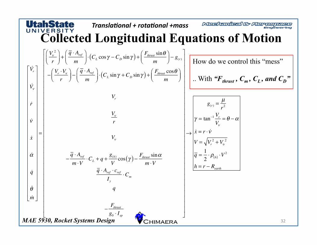
Collected Longitudinal Equations of Motion
32
Transla'onal + rota'onal +mass
How do we control this “mess”
.. With “Fthrust , Cm , CL , and CD”
!Vr
!V!
!r
!!
!x
!"
!q
!#!m
$
%
&&&&&&&&&&&&&&&&&&&&&&&
'
(
)))))))))))))))))))))))
=
V!2
r*+,
-./+
q 0 Arefm
*+,
-./0 CL cos1 2 CD sin1( ) + Fthrust sin#
m*+,
-./2 g(r )
2Vr 0V!
r*+,
-./2
q 0 Arefm
*+,
-./0 CL sin1 + CD sin1( ) + Fthrust cos#
m*+,
-./
Vr
V!
r
V!
2q 0 Arefm 0V
0CL + q +g(h)Vcos 1( ) 2 Fthrust sin"
m 0Vq 0 Aref 0 cref
Iy0Cm
q
2Fthrustg0 0 Isp
$
%
&&&&&&&&&&&&&&&&&&&&&&&&&&&&&
'
(
)))))))))))))))))))))))))))))
3
g(r ) =µr2
1 = tan21 VrV!
= # 2"
!x = r 0 !!
V = Vr2 +V4
2
q =120 5 h( ) 0V
2
h = r 2 Rearth
MAE 5930, Rocket Systems Design
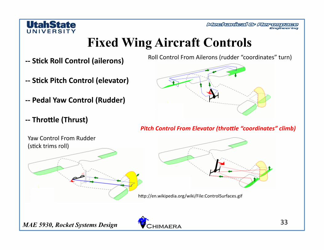
Fixed Wing Aircraft Controls
33
-‐-‐ S0ck Roll Control (ailerons)
-‐-‐ S0ck Pitch Control (elevator)
-‐-‐ Pedal Yaw Control (Rudder)
-‐-‐ Thro@le (Thrust)
Roll Control From Ailerons (rudder “coordinates” turn)
Pitch Control From Elevator (thro7le “coordinates” climb)
Yaw Control From Rudder (sGck trims roll)
hIp://en.wikipedia.org/wiki/File:ControlSurfaces.gif
MAE 5930, Rocket Systems Design
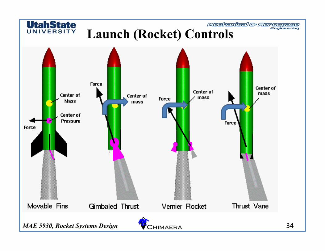
Launch (Rocket) Controls
34
MAE 5930, Rocket Systems Design
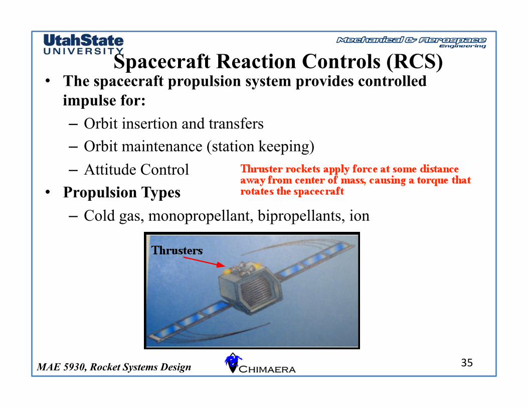
Spacecraft Reaction Controls (RCS) • The spacecraft propulsion system provides controlled
impulse for: – Orbit insertion and transfers – Orbit maintenance (station keeping) – Attitude Control
• Propulsion Types – Cold gas, monopropellant, bipropellants, ion
35
MAE 5930, Rocket Systems Design
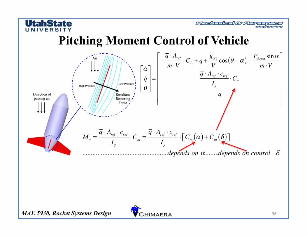
Pitching Moment Control of Vehicle
36
!!!q!"
#
$
%%%
&
'
(((=
)q * Arefm *V
*CL + q +g(r )Vcos " )!( ) ) Fthrust sin!
m *Vq * Aref * cref
Iy*Cm
q
#
$
%%%%%%%
&
'
(((((((
My =q ! Aref ! cref
Iy!Cm =
q ! Aref ! crefIy
! Cm "( ) + Cm #( )$% &'
...................................................depends on "........depends on control "# "
MAE 5930, Rocket Systems Design
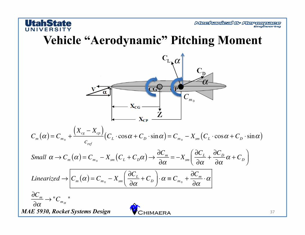
Vehicle “Aerodynamic” Pitching Moment
37
Cm !( ) = Cm 0+
Xcg " Xcp( )cref
CL # cos! + CD # sin!( ) = Cm 0" Xsm CL # cos! + CD # sin!( )
Small ! $ Cm !( ) = Cm 0" Xsm CL + CD!( )$ %Cm
%!= "Xsm
%CL
%!+%CD
%!! + CD
&'(
)*+
Linearized$ Cm !( ) = Cm 0" Xsm
%CL
%!+ CD
&'(
)*+#! , Cm 0
+%Cm
%!#!
%Cm
%!$ "Cm!
"
Cm 0
!
!
MAE 5930, Rocket Systems Design
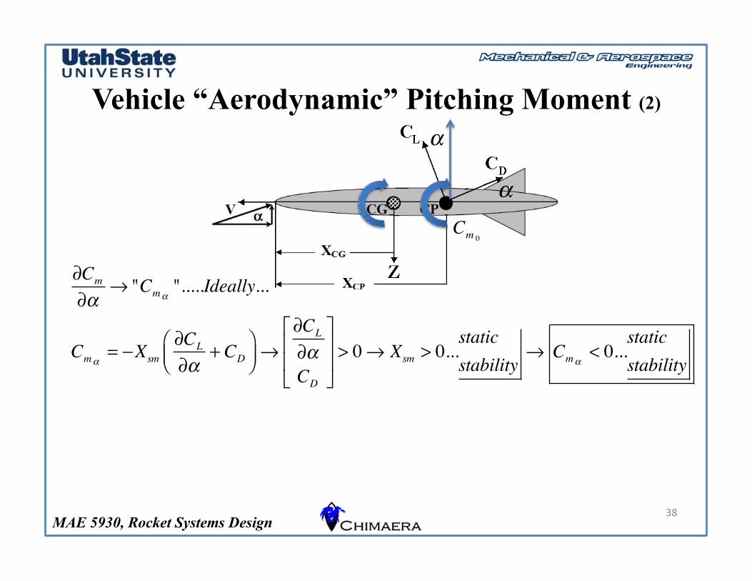
Vehicle “Aerodynamic” Pitching Moment (2)
38
Cm 0
!
!
!Cm
!"# "Cm"
".....Ideally...
Cm"= $Xsm
!CL
!"+ CD
%&'
()*#
!CL
!"CD
+
,
--
.
/
00> 0# Xsm > 0...
staticstability
# Cm"< 0...
staticstability
MAE 5930, Rocket Systems Design
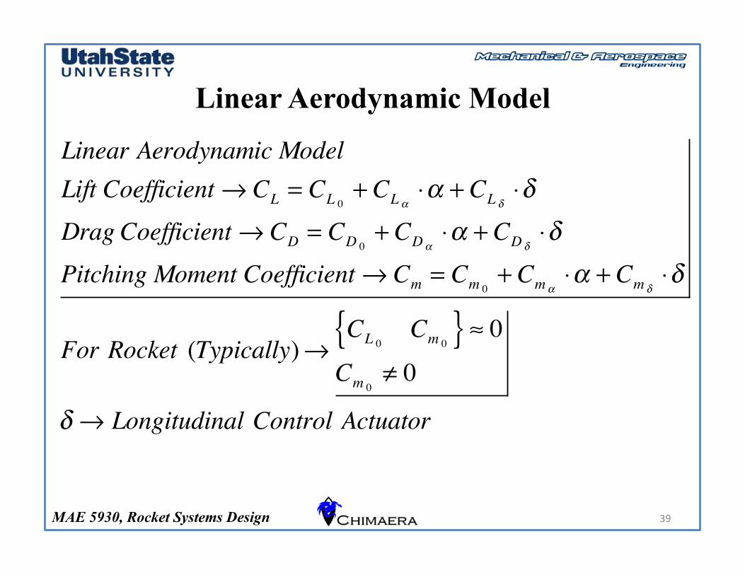
Linear Aerodynamic Model
39
Linear Aerodynamic ModelLift Coefficient ! CL = CL 0
+ CL "#" + CL $
#$Drag Coefficient ! CD = CD 0
+ CD "#" + CD $
#$Pitching Moment Coefficient ! Cm = Cm 0
+ Cm "#" + Cm $
#$
For Rocket (Typically)!CL 0
Cm 0{ } % 0
Cm 0& 0
$ ! Longitudinal Control Actuator
MAE 5930, Rocket Systems Design
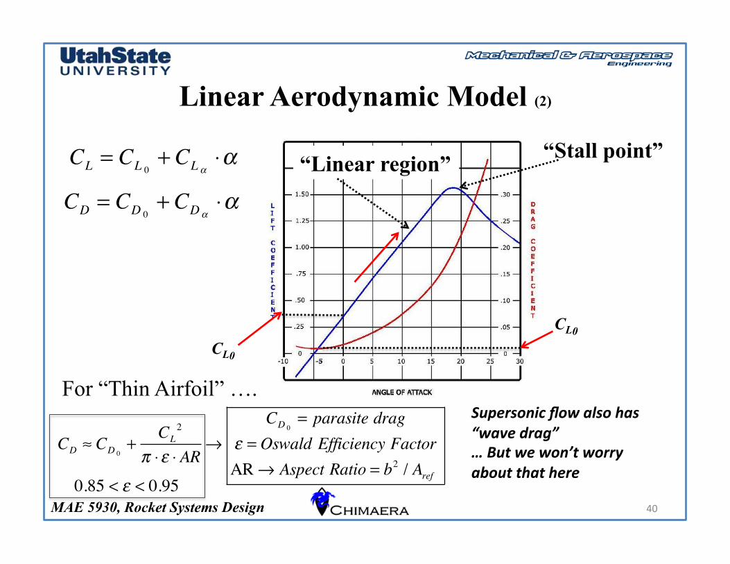
Linear Aerodynamic Model (2)
40
CL0
CL = CL 0+ CL !
"! “Linear region” “Stall point”
CD = CD 0+ CD !
"!
CL0
CD ! CD 0+
CL2
" #$ # AR%
CD 0= parasite drag
$ = Oswald Efficiency FactorAR % Aspect Ratio = b2 / Aref
For “Thin Airfoil” …. Supersonic flow also has “wave drag” … But we won’t worry about that here
0.85 < ! < 0.95

MAE 5930, Rocket Systems Design
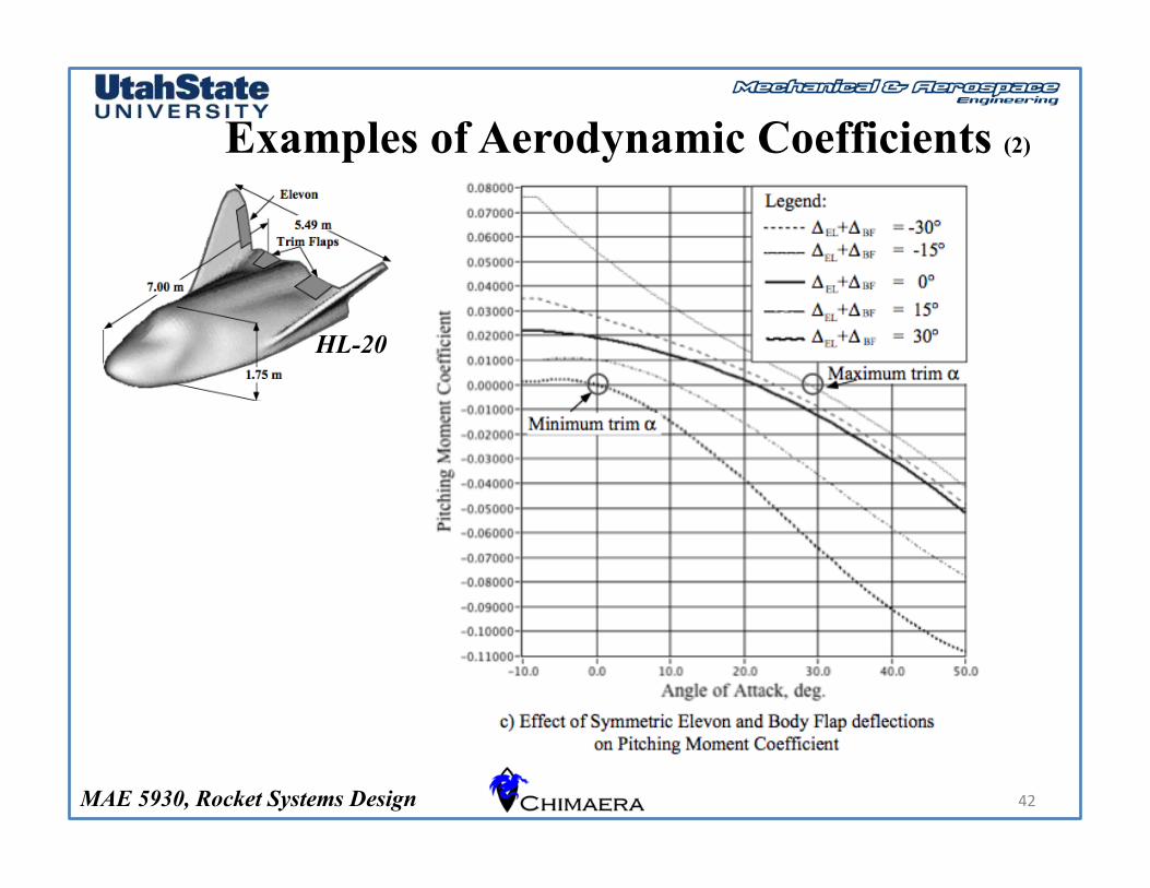
Examples of Aerodynamic Coefficients
41
HL-20 Lift Coefficient
Drag Coefficient
Pitching Moment Coefficient
MAE 5930, Rocket Systems Design
Examples of Aerodynamic Coefficients (2)
42
HL-20
MAE 5930, Rocket Systems Design
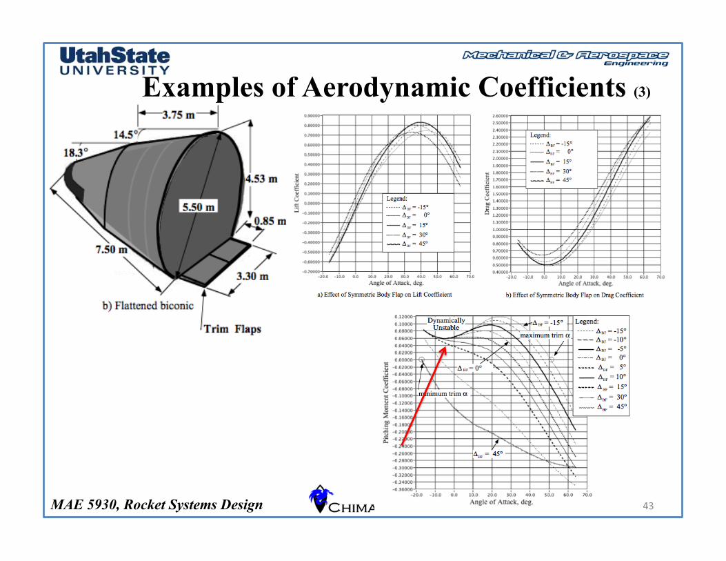
Examples of Aerodynamic Coefficients (3)
43
MAE 5930, Rocket Systems Design
Examples of Aerodynamic Coefficients (3)
44
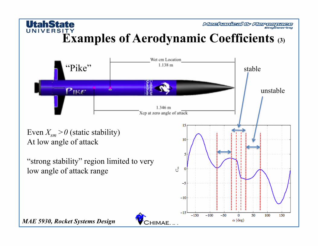
“Pike”
Even Xsm >0 (static stability) At low angle of attack
“strong stability” region limited to very low angle of attack range
stable
unstable
MAE 5930, Rocket Systems Design 45
Questions??