Embed Size (px)
DESCRIPTION
LOOP ANALYSIS. VSR. Loop Analysis. Nodal analysis was developed by applying KCL at each non-reference node. Loop analysis is developed by applying KVL around loops in the circuit. Loop (mesh) analysis results in a system of linear equations which must be solved for unknown currents. - PowerPoint PPT Presentation
Citation preview

LOOP ANALYSIS
VSR
VSR E&E Dept 1

Loop Analysis
Nodal analysis was developed by applying
KCL at each non-reference node.
Loop analysis is developed by applying
KVL around loops in the circuit.
Loop (mesh) analysis results in a system
of linear equations which must be solved
for unknown currents.
VSR E&E Dept 2

Example: A Summing Circuit
The output voltage V of this circuit is proportional to the sum of the two input voltages V1 and V2.
This circuit could be useful in audio applications or in instrumentation.
The output of this circuit would probably be connected to an amplifier.
VSR E&E Dept 3

Summing Circuit
Solution: Vout = (V1 + V2)/3
VSR E&E Dept 4
+
–
Vout
1k
1k
1k
V1 V2
+–
+–

Steps of Mesh Analysis
1.Identify mesh (loops).
2. Assign a current to each mesh.
3. Apply KVL around each loop to get an
equation in terms of the loop currents.
4. Solve the resulting system of linear
equations.
VSR E&E Dept 5

Identifying the Meshes
VSR E&E Dept 6
Mesh 2
1k
1k
1k
V1 V2Mesh 1+–
+–

Steps of Mesh Analysis
1. Identify mesh (loops).2.Assign a current to each mesh.3. Apply KVL around each loop to get an
equation in terms of the loop currents.
4. Solve the resulting system of linear equations.
VSR E&E Dept 7

Assigning Mesh Currents
VSR E&E Dept 8
1k
1k
1k
V1 V2I1 I2+–
+–

Steps of Mesh Analysis
1. Identify mesh (loops).2. Assign a current to each mesh.3.Apply KVL around each loop to
get an equation in terms of the loop currents.
4. Solve the resulting system of linear equations.
VSR E&E Dept 9

Voltages from Mesh Currents
VSR E&E Dept 10
R
I1
+ –VR
VR = I1 R
R
I1
+ –VRI2
VR = (I1 - I2 ) R

KVL Around Mesh 1
-V1 + I1 1k + (I1 - I2) 1k = 0
I1 1k + (I1 - I2) 1k = V1
VSR E&E Dept 11
1k
1k
1k
V1 V2I1 I2+–
+–

KVL Around Mesh 2
(I2 - I1) 1k + I2 1k + V2 = 0
(I2 - I1) 1k + I2 1k = -V2
VSR E&E Dept 12
1k
1k
1k
V1 V2I1 I2+–
+–
Steps of Mesh Analysis
1. Identify mesh (loops).2. Assign a current to each mesh.3. Apply KVL around each loop to get an
equation in terms of the loop currents.
4.Solve the resulting system of linear equations.
VSR E&E Dept 13

Matrix Notation
The two equations can be combined into a single matrix/vector equation.
VSR E&E Dept 14
2
1
2
1
k1k1k1
k1k1k1
V
V
I
I

Solving the Equations
Let: V1 = 7V and V2 = 4V
Results:I1 = 3.33 mA
I2 = -0.33 mA
FinallyVout = (I1 - I2) 1k = 3.66V
VSR E&E Dept 15

Another Example
VSR E&E Dept 16
1k
2k
2k
12V 4mA
2mA
I0
+–

1. Identify Meshes
VSR E&E Dept 17
Mesh 2
Mesh 3
Mesh 1
1k
2k
2k
12V 4mA
2mA
I0
+–

2. Assign Mesh Currents
VSR E&E Dept 18
I1 I2
I31k
2k
2k
12V 4mA
2mA
I0
+–

Current Sources
The current sources in this circuit will
have whatever voltage is necessary
to make the current correct.
We can’t use KVL around the loop
because we don’t know the voltage.
What to do?
VSR E&E Dept 19

Current Sources
The 4mA current source sets I2:
I2 = -4 mA
The 2mA current source sets a constraint on
I1 and I3:
I1 - I3 = 2 mA
We have two equations and three
unknowns. Where is the third equation?
VSR E&E Dept 20

VSR E&E Dept 21
1k
2k
2k
12V 4mA
2mA
I0
I1 I2
I3
The Supermesh surrounds this source!
The Supermesh
does not include this
source!
+–

KVL Around the Supermesh
-12V + I3 2kW + (I3 - I2)1kW + (I1 - I2)2kW = 0
I3 2kW + (I3 - I2)1kW + (I1 - I2)2kW = 12V
VSR E&E Dept 22
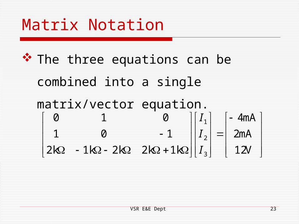
Matrix Notation
The three equations can be combined
into a single matrix/vector equation.
VSR E&E Dept 23
V12
mA2
mA4
1k2k2k1k2k
101
010
3
2
1
I
I
I

Solution
I1 = 1.2 mA
I2 = -4 mA
I3 = -0.8 mA
I0 = I1 - I2 = 5.2 mA
VSR E&E Dept 24

THANK YOU
VSR E&E Dept 25