Embed Size (px)
Citation preview
© ABB| Slide 1
Control of tethered wings for airbornewind energy
Lorenzo Fagiano, ABB Switzerland Ltd., Corporate Research, February 27th 2014
February 27, 2014

© ABB| Slide 2
The curse of optimalitya.k.a. the gap between control theorists and industry
February 27, 2014
“For sure my new approach works better than common industry practice, they usePIDs, or even just Ps with no Is and Ds”
“Nice paper. I just stopped reading when all those mathematics began”
“Yes, that’s optimal. However reality simply doesn’t work like that”
Application
Theory
Simulation
MotivationTest
Implementation
Application
Theory
Simulation
Motivation?
Ideally… …but more frequently

© ABB| Slide 3
Airborne wind energy
§ In wind towers, the outermost 30% of the blades contributes about 80% of thepower
§ Reduced generator cost + stronger (high-altitude) wind = cheaper energy, widerapplicability
Wind tower AWE
270 t ~ 16 t
February 27, 2014
© ABB| Slide 4
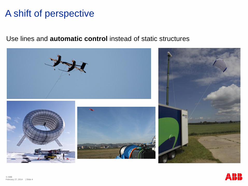
Use lines and automatic control instead of static structures
A shift of perspective
February 27, 2014

© ABB| Slide 5
KSU Winddirection
X
Y
Z
Traction phase
Passive phase
Ground-level generators
February 27, 2014

© ABB| Slide 6
Crosswind motion
2
32
22
cos( ) cos( )
cos( ) cos( )
1 112
eq
c
L eqeq
v E W
F C W
C AC EE
q f
q f
r
=
=
æ ö= +ç ÷ç ÷
è ø
Z
v
Y
X
q
f
W
Fc
Wind window
§ Eqs. of crosswind flight with constant line length:
February 27, 2014

© ABB| Slide 7
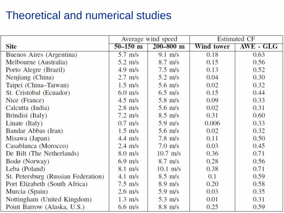
Theoretical and numerical studies
§ Due to wind variability, a wind generator is able to produce on average only afraction of its rated power, called “Capacity Factor” (CF):
§ The Capacity Factor depends on:
§ power curve of the generator
§ wind speed at a given location
ave maxP P CF= ×
February 27, 2014

© ABB| Slide 8
Wind shear model at De Bilt (NL)
Histograms of wind speed at De Bilt (NL)
200-800 m50-150 m
Theoretical and numerical studies
February 27, 2014
© ABB| Slide 9
Theoretical and numerical studies

© ABB| Slide 10
(Documented) Research & Development in AWE
1980 2000 2005 2008 2011
Theory
Numericalanalyses
Experiments
February 27, 2014
Good number ofpapers on controlaspects but still nodocumentedsuccessful automaticcontrol strategy!

© ABB| Slide 11
Control approach – previous works
§ Example: (quite) detailed nonlinear model + EconomicNMPC + Fast MPC technique with offline approximation
Obtain state-feedback control law:
( ),x pd k=
February 27, 2014
Canale, Fagiano, Milanese,IEEE TCST 2010
Application
Theory
Simulation
Motivation?

© ABB| Slide 12
Manipulatedvariables
Controltasks
Steering deviation
Power/depower
Line force
Autonomouscrosswind flight
Power maximization
Focus on the traction phase
Controls in airborne wind energy
February 27, 2014

© ABB| Slide 13
Manipulatedvariables
Controltasks
Steering deviation
Power/depower
Line force
Autonomouscrosswind flight
Power maximization
Use the steering deviation to achieve crosswind flight
Control design approach
February 27, 2014
© ABB| Slide 14
Research project at UC Santa Barbara
§ Ultimate goal: demonstrate autonomous crosswind flight of a tetheredflexible wing.
§ Achieve 4 hrs continuous unattended flight with figure-8 paths
§ Constant line length
February 27, 2014

© ABB| Slide 15
Modeling Filtering
Mechanical design:Trevor Marks - UCSB
Control design
Research project at UCSB
§ 1 year long (12/11 – 11/12)
§ $ 95,000 total ($ 25,000 materials, $ 50,000 salaries)
February 27, 2014

© ABB| Slide 16
Timings
1/12 3/12 5/12 8/12 10/12
February 27, 2014

© ABB| Slide 17
Control objective and control input
Control objective: make the wing follow“figure-eight” paths in crosswindconditions
Control input: difference of length ofthe steering lines, d
Leading edge
Leftsteeringline
Rightsteeringline
Power line
February 27, 2014

© ABB| Slide 18
Prototype overview
§ No energy generation
§ 2 and 3-line kites
§ ± 1.2 m steering lines’ lengthdifference
§ 0 to 0.5 m power line shortening
February 27, 2014

© ABB| Slide 19
Mechanics & actuators
§ Linear motion system forsteering lines
§ Aluminum framing
§ 400 W motor for steeringlines
§ 350 W motor for power line
February 27, 2014
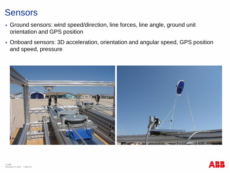
© ABB| Slide 20
Sensors§ Ground sensors: wind speed/direction, line forces, line angle, ground unit
orientation and GPS position
§ Onboard sensors: 3D acceleration, orientation and angular speed, GPS positionand speed, pressure
February 27, 2014

© ABB| Slide 21
Electronics and control hardware
§ Batteries and 1100 W inverter
§ Measurement and control algorithmscompletely developed with xPC Target(Matlab/Simulink) tools
February 27, 2014

© ABB| Slide 22
Testing site
§ Oxnard Shores,Oxnard, CA
§ No obstacles
§ Prevalent wind fromwest, typically 2 to 6m/s W
February 27, 2014

© ABB| Slide 23
Does it make sense?
§ No energy generation, only 30 m line length
§ BUT…
§ Control problem more difficult, due to small maneuvering space: delaysand position errors are more critical, easier to get close to the border ofthe wind window
§ Low altitude allows reasonably good measurement/estimate of allvariables (e.g. wind speed)
§ Full set of data available
§ Easier to test, no need for authorization
§ Results are meaningful also for longer lines and larger size
February 27, 2014
© ABB| Slide 24
Control problem
§ Nonlinear, uncertain, time-varying dynamics, relatively fast
§ Constraints on control input and system trajectories
§ External disturbance (change of wind direction and speed, turbulence)
February 27, 2014

© ABB| Slide 25
Experimental results
MOVIE..
February 27, 2014
© ABB| Slide 26
Employed control approach
February 27, 2014
§ P controller
§ Kalman filter
© ABB| Slide 27
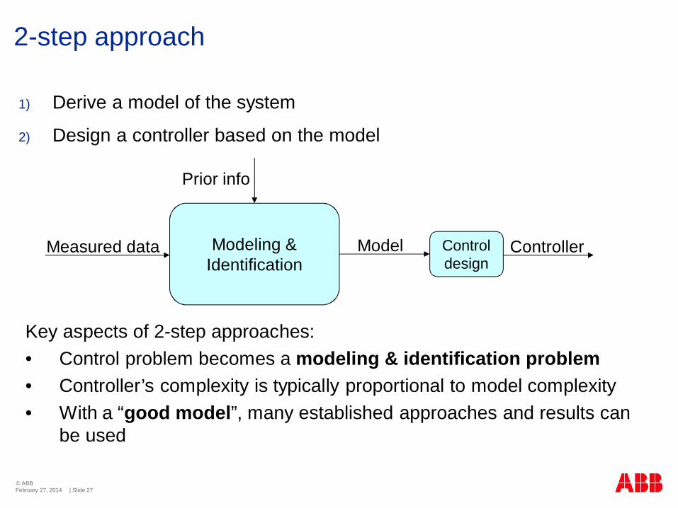
2-step approach
1) Derive a model of the system
2) Design a controller based on the model
Measured data
Prior info
Modeling &Identification
Controldesign
Model Controller
Key aspects of 2-step approaches:• Control problem becomes a modeling & identification problem• Controller’s complexity is typically proportional to model complexity• With a “good model”, many established approaches and results can
be used
February 27, 2014

© ABB| Slide 28
Modeling – velocity angle
LN
LE
Z
v
g
LD
Y
X
q
f
The velocity angle g givesinformation on the wing’sconfiguration with just ascalar
February 27, 2014

© ABB| Slide 29
Modeling – velocity angle
The velocity angle g gives information on thewing’s configuration withjust a scalar
gv
LN
g can be seen as the“turning rate” of the wing
.
February 27, 2014

© ABB| Slide 30
Modeling – velocity angle
§ g can be seen as the “turning rate” of the wing
Conceptually similar to yaw rate vs. front steering for vehiclesSimilar models proposed by Erhard, TCST 2013, and Delft group
Derived the following model from first principles:
February 27, 2014
.

© ABB| Slide 31
Modeling – velocity angle
6m2 kite 9m2 kite
Model is an integrator with time-varying positive gain → good model
February 27, 2014

© ABB| Slide 32
• Kc is a static scalar gain
• Can use gain scheduling if needed/wanted
• Guaranteed robustness vs. wide range of conditions
Velocity angle control
February 27, 2014
© ABB| Slide 33
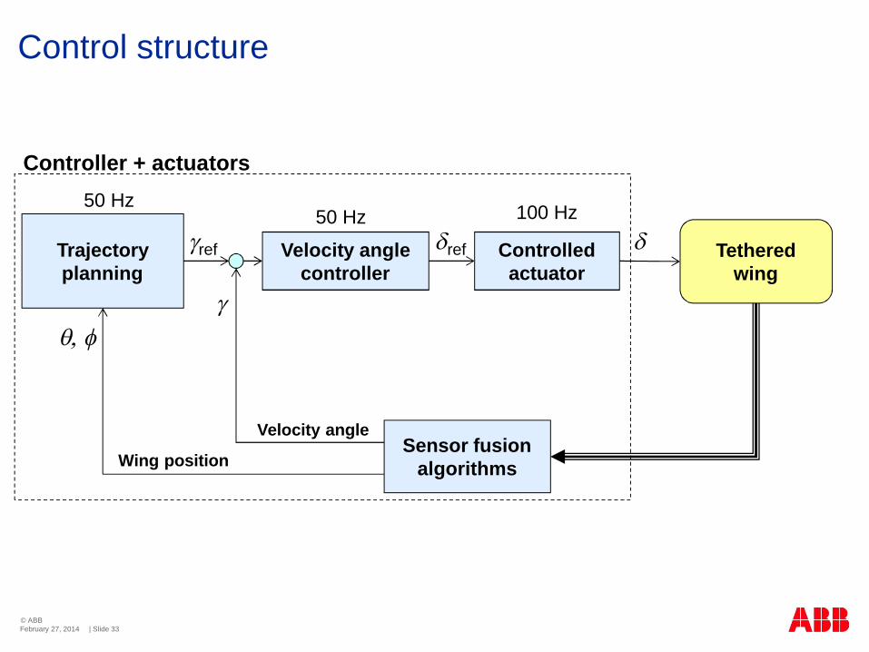
Control structure
Trajectoryplanning
Velocity anglecontroller
Velocity angle
Wing position
100 Hz50 Hz50 Hz
Tetheredwing
Controlledactuator
q, f
gref
g
dref d
Sensor fusionalgorithms
Controller + actuators
February 27, 2014

© ABB| Slide 34
Trajectory planning
TrajectoryPlanning
1 2
February 27, 2014

© ABB| Slide 35
Experimental results
• More than 22 hrs of autonomous flight, longest flight > 4 hrs (note: NOreeling capabilities)
• 3 different wings, wind speed from 3 to 6 m/s, always the same tuning
• No need for wind speed measurement
• Easy to implement and tune
• The same controller is now being used on different prototypes withreeling capabilities, e.g. Swiss Kite Power, and by companies
February 27, 2014

© ABB| Slide 36
Sensor fusion and filtering
System
Observer
d y
x̂
Observer design based on thesame system model as the oneused for control design
NOT a good approach in this case
• Model is complex, uncertain,nonlinear, time-varying
February 27, 2014
© ABB| Slide 37
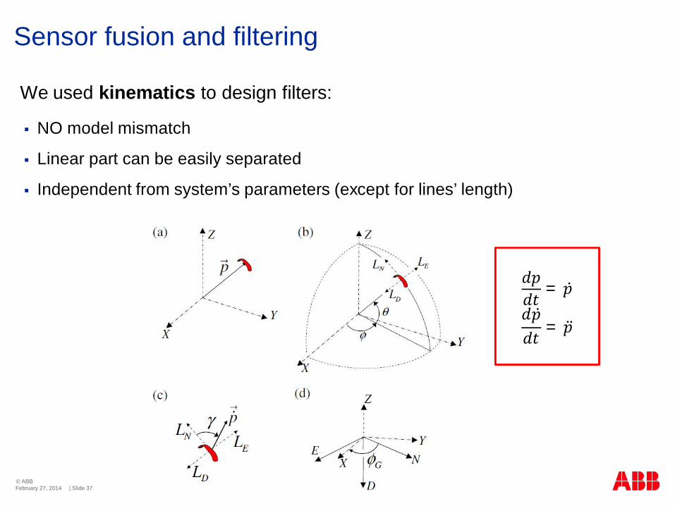
Sensor fusion and filtering
§ NO model mismatch
§ Linear part can be easily separated
§ Independent from system’s parameters (except for lines’ length)
We used kinematics to design filters:
February 27, 2014
= ̇̇= ̈

© ABB| Slide 38
Sensor fusion and filtering
§ NO model mismatch
§ Linear part can be easily separated
We use kinematics to design our filters:
Lineardynamics
Nonlineardynamics
Static invertible functions
February 27, 2014
= ̇̇= ̈
© ABB| Slide 39
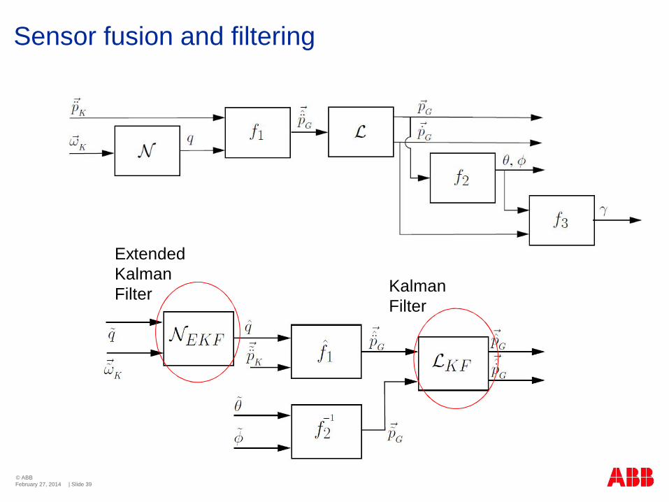
Sensor fusion and filtering
ExtendedKalmanFilter Kalman
Filter
February 27, 2014

© ABB| Slide 40
Sensor fusion: experimental results
The line angle measurement alone can give satisfactory results (for feedback control);the use of an IMU improves the estimate by reducing the lag
with IMU measurements without IMU measurements
Line angle measure (gray)Line angle measure (gray)
February 27, 2014

© ABB| Slide 41
Lots of interesting problems for control engineering:
• Adaptation -> CDC 2013• Modeling• Estimation• Reeling and pitch control -> IFAC world congress 2014• Fault tolerance• Take-off and landing• …
Also lots of interesting aspects in other fields:
• Aerodynamics and wing design• Materials and mechanical design• Power conversion• Wind measurement• …
Next steps
February 27, 2014

© ABB| Slide 42
The curse of optimalitya.k.a. the gap between control theorists and industry
February 27, 2014
§ Many aspects are extremely important in applications, but not considered at allwhen developing new theory or when seeking “optimality”, e.g. complexity andeasiness of implementation
§ A deep understanding and/or «good» problem formulation can lead to solutionsbased on well-assessed theory, beating any «advanced» approach
§ Reasonable approach to develop new theory: try to explain why things work


![2016-07-13 [MPC in the Real World][Harvard Dataverse Workshop] › ~best › research › talks › MPCinRealWorld.pdf · 3. BJ’s Wholesale Club 4. Blue Cross Blue Shield of Massachusetts](https://img.pdfslide.net/doc/110x75/5f0d58d77e708231d439e62a/2016-07-13-mpc-in-the-real-worldharvard-dataverse-workshop-a-best-a-research.jpg)