Embed Size (px)
Citation preview

LOST-WAX CASTING A Practitioners Manual
Wilburt Feinberg
Edited and illustrated by Jim Byrne

Lost-wax casting
A practitioner’s manual
by Wilburt Feinberg
edited and illustrated by Jim Byrne
)i'pa PUBLISHING

Published by ITDG Publishing 103-105 Southampton Row, London WC1B 4HL, UK
© ITDG 1983
First published in 1983 Reprinted 1994, 1998, 2001
ISBN 0 903031 88 4
A catalogue record for this book is available from the British Library.
Acknowledgement Financial assistance in the production of this book was made available through Intermediate
Technology Industrial Services from a grant form the Overseas Development Administration. Their assistance is gratefully acknowledged.
ITDG Publishing is the publishing arm of the Intermediate Technology Development Group. Our mission is to build the skills and capacity of people in developing countries through the
dissemination of information in all forms, enabling them to improve the quality of their lives and that of future generations.
Printed in Great Britain by Russell Press, Nottingham.

Contents
Author’s preface v
1 Introduction 1
Part 1: The lost-wax casting process
2 Primitive lost-wax casting 7
3 Preparing and moulding the wax 11
4 Moulding wax patterns 14
5 Investment mould coatings 23
6 Burn-out and casting 25
Part 2: Construction techniques
7 Preparing clay mixtures 29
8 Constructing a crucible furnace 34
9 Building a burn-out oven 49
10 Crucible-making and maintenance 58
11 Preparing non-ferrous metals for casting 61
Appendices
1 Case studies 67
2 Review and check list 70
3 Glossary of casting terms 72
4 Bibliography 74
5 Useful data 74
The photographs in the text were taken by the author.

THIS PAGE IS BLANK but this is not a printing or scanning
fault and no content is missing.

Author’s preface
This manual sprang from the need to record the work of the past, and the desire to inspire simple, basic improvements in the casting methods currently used in developing countries. It is offered to technical assistance personnel and, indeed, anyone wishing to learn about improved techniques. Its aim is to highlight the immense scope which exists for immediate improvements in precision lost-wax casting.
Purpose of the manual
The technique of lost-wax casting has three main areas of application today:
1. As a precision casting method in industry. 2. For craftsmen working in cast metals. 3. As a low-cost method of producing precision metal
castings, both aesthetic and functional, where facilities, equipment and funds are limited.
This manual has been written for the craftsman and the person with limited money, and is based on my experience in developing easily accessible techniques for making both cultural objects and castings for small industry in developing countries. It arises primarily from the need to make my techniques and unique approach to the technical problems involved in lost-wax casting more widely known; it will also appeal to the craftsman who wants to be intimately involved with the materials and processes of his craft.
Just as we have witnessed a remarkable renaissance of small-scale pottery throughout the world this century, this manual could provide the stimulus for a revival of cast-metal crafts. It is also intended to build on the traditional skills of metal craftsmen throughout Africa, Asia and Latin America as they seek to respond to the changing needs of rural industrial development.
The approach
This manual is much more an attempt to encourage resourcefulness than a precise series of instructions on how to build the necessary equipment, and make wax models and metal castings. The fact that a particular type of clay or fuel or piece of equipment is not available has never yet prevented me from making castings, and I have done this in some pretty

remote and unlikely situations. Nor can a rigid approach achieve results in social and cultural conditions which vary as widely as the backgrounds of those who will use the book.
Those acting as instructors will need to be particularly sensitive to the cultural heritage of the people with whom they are working. They should be open to the potential of materials and ideas as they find them and not as they might wish them to be.
Structure of the manual
This manual has been designed to ensure maximum clarity and ease of use and is divided into two main parts. The first part deals with the various processes in lost-wax casting, the second part with the equipment required to carry out these processes successfully, the construction of a melt furnace, a burn-out oven and a home-made crucible. The selection and preparation of scrap metal are dealt with in the final chapter. A series of appendices include a review of the process, two case studies that I have carried out to demonstrate some of the problems the reader might face, a glossary, a bibliography and some useful data.
A ckno wledgemen ts
I am indebted to, and pleased by the positive approach of Intermediate Technology Industrial Services, who have encouraged me in my work and in writing this manual. I would also like to thank the Third World craftsmen who have taught me so much about their cultures, religions and art forms. Without their patience, this ‘modern technologist’ would still be living in the Dark Ages.
Wilburt Feinberg January 1983

1
Chapter 1. Introduction
Lost-wax casting
Lost-wax casting is an ancient technique for making a precise replica of an object by casting it in molten metal. The master model for the casting is created in wax, which is then covered with a refractory (heat-resistant) shell of soft clay or a clay- based slurry. The wax model and its thick coating are fired to harden the clay mould and at the same time to melt out the wax — hence the term ‘lost-wax’. The mould cavity contains a perfectly detailed impression of the original model. Molten metal is poured into the mould and when this has solidified the mould is easily broken to release the casting.
The precision of this method of making castings in precious and industrial metals is such that little finishing is required and the finest details can be reproduced — so much so that an adaptation of the basic technique is used to produce high-precision castings for the aircraft and general engineering industries. It also has the advantage that ‘under¬ cuts’ (see Glossary) can be reproduced without any of the difficulties experienced with other casting techniques. Hence its long-standing use by artists and craftsmen the world over, as well as its many modern industrial applications.
The process has changed very little over the centuries, though variations in technique have been developed in different areas of the world. Craftsmen in ancient India and Egypt were probably the earliest practitioners. The most outstanding aesthetic and technical producers have included the casters of the Shang, Chou and Han dynasties of China, the makers of the great bronzes of Nara and Mamakura in Japan, the artists of the Golden Age in Greece and of Imperial Rome, the art foundries of Renaissance Italy, the cast-gold workers of Central and South America, the people who cast the images of the ancient deities of Nepal and Tibet, and the creators of the bronzes of Ife and Benin in Africa.
Employment and wealth generation
Casting is a labour-intensive business, and will remain so as long as the process continues in its present stage of development (or lack of it). Generally certain mechanical ‘aids’ can be introduced, but by and large it takes skilled and trained people to produce castings in this context. Throughout the process of precision lost-wax casting, many

2
‘hands’ are required to reach the ultimate goal of producing a sound and beautiful product. Those ‘hands’ sometimes serve a life-long apprenticeship and are only allowed to do creative work on their own after many years of devoted study. In some instances, the creative part of the model is produced by repetition and not by an artistic endeavour; and unfortunately, modern times have sometimes encouraged the production of shoddy, unaesthetic merchandise, lacking in quality and unrelated either to its ethnic past or current industrial needs.
Even though the basic art has suffered the degeneration of modernization, employment seems to have thrived. Yet we should not be misled into thinking that because castings are sometimes sold for a comparatively high price, the benefit is passed on to the workers. In the author’s experience the wealth generated by this business lies in the hands of the principal and not with labour. But in most cases the mere fact that people are employed and have a ‘bare existence’ wage is far better than no employment at all. It is to be hoped that an introduction of improved technology, an increase in markets and the development of new product lines will give financial benefits to the actual people responsible for development.
Potential for development
Two distinct ways exist for development. One is on a scale far above the needs of the small village caster; the other can give direct assistance to the caster.
The former (in many cases) requires advanced technology and large financial inputs, and has no place in the scope of this manual. Instead we shall concern ourselves with the ‘jump’ from the most basic primitive lost-wax casting to one of an improved standard. This jump involves, and leads to, the introduction of certain controls, simple equipment and simple industrial standards that can together open the way for basic precision industrial castings — objects at present in great demand. The introduction of a uniform standard, producing high-quality uniform castings is directly contrary
Some completed products, Ghana

to the current method of casting as practised in many Third World countries. In most cases at present, the appeal of products of the lost-wax process lies in the slight imperfection and unique handling of the subject and material. Our new approach may present problems in the initial stages, but once the benefits of improved methods are gained and understood, the result can only be advantageous to the producers.
Since in most cases in the field of technical assistance the craftsman is basically familiar with casting, the changes described here should not be difficult, but the process takes patience, understanding and persistence on the part of the introducer. An explanation and a demonstration is necessary to show why improved quality, less expensive production methods and increased output — all in terms that are understood in the Western context of business — are important to the caster. This will have to be introduced in a context and at a level far lower than most Western technologists can imagine, but they must be introduced for the craft to survive at all. When the peasant caster handles his operations as a viable business then it has a much greater chance of succeeding.
Improving existing operations
It is not difficult to improve existing methods of production. One has to know exactly what problems are plaguing the operation and then, with the approval of the manufacturers, proceed with the work in hand. One major problem facing the introduction of new methods and techniques will be the interpretation of the real problem. Unfortunately, in most cases the existing manufacturers cannot analyse the problem, and so the responsibility falls upon the introducer. This very fact can of course have adverse effects if confidence is not fully established between the parties. Once equal trust is present — knowing what has to be done — the work has a chance of proceeding easily.
It must be clear from the above that the responsibility for development must start with the introducer. At this stage, it should not be assumed that the man who has been producing castings for all of his life can suddenly blossom and come up with radically changed methods, contrary to the tried and trusted method he now uses. Since this manual will discuss many possible improvements in the casting process, one must analyse the needs of the existing producer before his introduction to the new methods. Certainly improvements can be successfully introduced once the reader feels confident in the techniques laid out — but proceed with caution!
New techniques for new products
Lost-wax casting has great potential for the development of all kinds of products. Although the range of products manufactured by this process in developing countries is, in most cases, restricted to art objects, it could be extended to

4
The product, a pelton wheel for a micro hydro project,
Colombia.
encompass industrial products. These might include bush bearings, pillow blocks, machinable stock, hardware and plumbing fittings, pulley wheels, pump parts, household items and machine parts — and this list is far from complete. If standard methods of production were established, a broad range of ideas could tried, tested and made viable. This manual, however, is essentially concerned with laying the foundations for such a development, through the introduction of the necessary technologies and production techniques.

PART 1: THE LOST-WAX CASTING PROCESS

THIS PAGE IS BLANK but this is not a printing or scanning
fault and no content is missing.

7
Chapter 2: Primitive lost-wax casting
Although differences in the process were found in most countries visited by the author, the general process always begins with making a clay core (if the finished piece is to be hollow-cored) which is roughly the shape and size of the desired end-product. Wax is rolled or beaten out on a board and pieces are cut off with a knife, applied to the core, and modelled with the fingers. The detailed forms are then modelled. The model is covered with a coating of very smooth clay mixed with cow dung, horse dung, charcoal, rice husks etc. The clay-covered wax model is dried and another layer of clay mixture is applied. In some cases a third layer of clay mixture is added to give extra strength to the final mould.
The dried mould is placed over a hole in the ground, with the pouring cup (through which the molten metal will be introduced) as the base. A fire is made over or around the mould and the wax is allowed to run out through the pouring cup on to the earth or into a receiving receptacle. The wax- free mould is removed from the pit and rubbed with wet earth. It is then placed over the hole again, in the same position, and heated slowly to ensure that the earth hardens and seals any cracks. The mould is now ready for casting.
Meanwhile, the metal is placed in a crucible and heated in a charcoal forge fire. When mould and metal are judged ready for pouring, the mould is removed from the fire, using tongs, and stood upright in soft earth. The crucible is removed from the forge fire, again using tongs, and the metal is poured until the mould is filled. Several moulds can be filled at one time. Any remains of metal in the crucible are poured off on to the earth and salvaged for future casting.
Another method is to use an individual crucible that is
added directly to the individual mould. Once the mould has dried and been ‘burned-out’ (all the wax removed), a crucible is attached to the open end of the mould containing the required metal scrap, with a clay/cow-dung/cereal mixture. This ‘two-part’ mould is heated to about the temperature at which the metal melts (see Appendix 5), then removed from the charcoal forge and a small hole punctured in the metal container end of the unit. If the metal is judged ready for pouring (a decision the caster bases on experience), the mould is inverted so that the liquid metal flows by gravity into the opening in the mould.

8
Fig. 1 The completed wax pattern.
This method has many advantages, but, unfortunately, many disadvantages too. The advantages are that it uses the exact amount of metal required, it avoids the introduction of unwanted gases because of the closed crucible, individual casting, and the fuel consumption is low. The main disadvantage is not really knowing when the metal is ready for casting. Metal melts approximately 200°C lower than the temperature it should be cast at; it is difficult to determine the exact moment of pouring by looking inside a dark, small opening in a mould. Another disadvantage is the handling of the mould, as once the wax has been burned-out the mould is very fragile: small pieces could break off inside the sprue (the channel connecting the pouring cup with the mould cavity) and obstruct the flow of metal. Also, once the crucible is punctured the vacuum formed inside is broken and a rush of unwanted gases enters the crucible. Another disadvantage is that the uneven heat is constantly changing with the intensity of the fire, the location of the mould and the variance in wall thickness.
After a short cooling period, the moulds are placed on their sides to shake out the casting and sprinkled with water, which helps to cool it. The mould is carefully knocked off with a small hammer until the softer, black, inner layer is reached. The final remains of the mould are scraped or brushed off with an old saw blade or wire brush. The sprues are cut away, any ‘fins’ are filed off, and the surface is chiselled, ‘chased’ and polished.
Fig. 2 Sectional view of the clay-coated wax pattern.
A Section through wax.
B Section through clay coating.
C Surface detail.
DIAGRAMATIC REPRESENTATION OF THE PROCESS
9
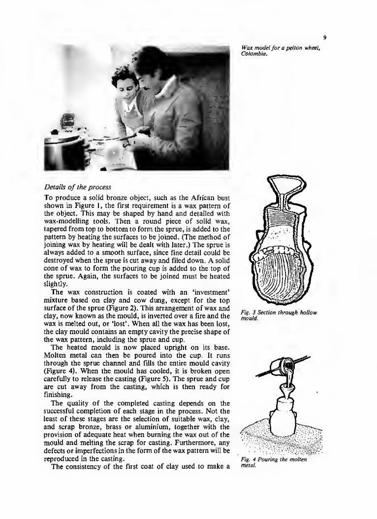
Details of the process
To produce a solid bronze object, such as the African bust shown in Figure 1, the first requirement is a wax pattern of the object. This may be shaped by hand and detailed with wax-modelling tools. Then a round piece of solid wax, tapered from top to bottom to form the sprue, is added to the pattern by heating the surfaces to be joined. (The method of joining wax by heating will be dealt with later.) The sprue is always added to a smooth surface, since fine detail could be destroyed when the sprue is cut away and filed down. A solid cone of wax to form the pouring cup is added to the top of the sprue. Again, the surfaces to be joined must be heated slightly.
The wax construction is coated with an ‘investment’ mixture based on clay and cow dung, except for the top surface of the sprue (Figure 2). This arrangement of wax and clay, now known as the mould, is inverted over a fire and the wax is melted out, or ‘lost’. When all the wax has been lost, the clay mould contains an empty cavity the precise shape of the wax pattern, including the sprue and cup.
The heated mould is now placed upright on its base. Molten metal can then be poured into the cup. It runs through the sprue channel and fills the entire mould cavity (Figure 4). When the mould has cooled, it is broken open carefully to release the casting (Figure 5). The sprue and cup are cut away from the casting, which is then ready for finishing.
The quality of the completed casting depends on the successful completion of each stage in the process. Not the least of these stages are the selection of suitable wax, clay, and scrap bronze, brass or aluminium, together with the provision of adequate heat when burning the wax out of the mould and melting the scrap for casting. Furthermore, any defects or imperfections in the form of the wax pattern will be reproduced in the casting.
The consistency of the first coat of clay used to make a
Wax model for a pelton wheel, Colombia.
Fig. 3 Section through hollow mould.
Fig. 4 Pouring the molten metal.

10
Fig. 5 Shattering the mould to release the cast bust.
Putting the first coat of refractory material onto the
model, Colombia.
A mould inside the furnace, Colombia.
mould is also very important. If this is coarse, then the resulting casting will not have a smooth surface. Adequate drying of the mould in a well ventilated area is crucial, because a mould will crack when fired during burn-out. Moulds cannot be dried out by direct heat.
When the mould is dry, the wax can be burned-out in preparation for casting. In much of the Third World, the burn-out and casting operations are still done over open-pit forge fires. However, the use of a furnace and burn-out oven, as described in Chapters 8 and 9, will undoubtedly improve the speed and efficiency of existing operations. The purpose of the burn-out is to dispose of the wax and harden the moulds. Four to six hours of steady heat at 800°C will produce moulds of a low-fired ceramic quality which possess the strength to withstand the pressure and temperature (up to 1,500°C) of molten metal during casting.
When the mould has been in the burn-out oven for over four hours, the preparation of the metal should be started so that molten metal will be ready for casting when the burn-out operation is complete. A red glow in the sprue openings of the mould shows that it is ready for casting. It should be removed from the oven with tongs carefully handled to prevent cracking, and stood upright in sand. At this point, if the molten metal was poured into the very hot mould, the metal would start boiling. Thus the temperature of mould must be reduced to a level determined by the metal being cast. Aluminium should be cast into a mould at a temperature of approximately 300°C. Bronze/brass should be cast into a mould at a temperature of approximately 600°C. Experimentation and experience will provide the exact moment for casting. The sand is immediately packed around the mould to provide support. The molten metal is then produced, without any delay, and poured from a crucible in a steady flow until the mould is full to the top of its pouring cup.
Modelling wax patterns
As already stated, despite other variations observed by the author, in general lost-wax casting always begins with the preparation of the wax pattern if the casting is to be solid. On the other hand, if the casting is to be hollow, the process begins with the making of a suitable clay core; the recipe for clay and cow dung core-making is given in Chapter 7. The core is made to resemble roughly the desired form of the finished casting.

11
Chapter 3: Preparing and moulding the wax
The best type of wax to use in model- and pattern-making is one which is pliable rather than brittle. It should be solid at room temperature, soft when handled and should not melt until it approaches the boiling point of water. Good pattern¬ making wax should have little ‘memory’. That is to say, if it is bent, it will not creep back to its original shape. Another important characteristic of the wax to be used is that if a portion of a ball of the wax is scooped out, the opposite side of the ball should not expand under this pressure. It must also be impossible to twist or cut the wax without causing cracking, and the wax must be able to stick to itself, so that it can be built up in layers. Finally, a good wax will normally be a dull colour and opaque, otherwise it would not be possible to see the precise shape of its surface during modelling. This is absolutely essential, particularly for people just beginning to work with wax.
The best waxes used by the author, and recommended to people working in developing countries, are mixtures based on beeswax, paraffin wax and petroleum. Two recipes are included here which have been used in different situations. Both of them are prepared by melting, but not boiling, the ingredients in a double boiler, pouring the resulting liquid into trays and allowing it to set in flat slabs, ready for use. Double boiling simply involves inserting a medium-sized saucepan into a larger one and half-filling the cavity between them with boiling water.
The range of possible wax recipes is, of course, far more extensive than is indicated below. A variety of additives can be used, such as ‘mastic’ and ‘damar’, which are soft resins derived from trees; or copal and amber, which are hard resins derived from fossils, plants and trees. Mutton and beef tallow are also used. The type and proportion of the additives depend on the desired characteristics of the wax: hardness, softness, suitability for carving, stickiness, accuracy in reproduction by moulding, melting point, and rate of thermal expansion in the mould. There is no alternative to experimentation when deciding on a suitable wax for long¬ term use. Depending on the additives used, the melting range of modelling waxes is roughtly 50 to 100°C.
Preparing a wax pattern for the mould make-up.
Moulds cooling and waiting to be broken, after pouring, Upper Volta.

12
Wax mould of a pelton wheel, Colombia
Fig. 6 Molten wax poured into a cone.
Fig. 7 The dirty wax at the tip of the cone has been cut away.
Fig. 8 Kneading the wax.
Recipe 1
Paraffin wax (60-65°C melting point) 4 parts Refined beeswax 1 part
Blend into this wax mixture 10 to 15 per cent (by volume) powdered damar, or preferably copal or amber. Add approximately 5 per cent (by volume) clear polythene (polyethylene). This can be done by melting in either clean, transparent food bags, or commercially available polythene granules. Also add some crayon chips to provide some colour. This will make it easier to inspect surface detail of the wax patterns.
The use of polythene is justified on the grounds that, in every village where the author has worked, polythene bags have been available. The results have always been more than satisfactory. If food bags are being used, but it is not certain whether they are made of polythene, try melting one bag into the refined molten wax. If it does not melt, it is not polythene. The advantage of adding polythene is that it adds body, strength and smoothness to the wax patterns, which is particularly important if the wax is to be moulded in silicone rubber moulds.
Recipe 2
Refined beeswax Paraffin wax Petroleum oil Petroleum jelly Cocoa butter
(or heavy coconut oil or clarified animal fat/dripping)
30 per cent 30 per cent 15 per cent 15 per cent
10 per cent
As with the first recipe, add to this about 5 per cent by volume clear polythene.
Refining beeswax
Natural beeswax must be refined before it is used. In its raw state, it tends to contain dead bees, dirt and other solid matter, which must be removed. This is done by melting the beeswax, stirring it thoroughly and pouring it into a cone- shaped vessel. The cone may be made by rolling up a sheet of tin, heavy card or paper. When the molten wax is poured into the cone, all foreign matter in the wax has cooled and set, it can be removed from the cone and the dirty wax at the tip cut away. The wax is then melted again and poured on to the surface of some warm water. Before it has time to congeal, however, it must be thoroughly kneaded by hand.
As the molten wax is compressed in the hands, it will chip into little slabs which are so hard when cool that they cannot be worked by hand. These slabs must therefore be broken up into tiny pieces. The pieces will be a dull colour, but essentially opaque, and therefore suitable for use. If the wax is not properly kneaded, it will appear translucent.
Once the beeswax has been refined and allowed to dry, it

13
can be mixed according to one of the recipes given above. Either recipe will produce a modelling wax which will melt at approximately 85°C. When the author worked in Papua New Guinea and Africa, the temperature for wax melt was 74°C. Without thinking about any possible adverse effects, he used the same formula in Bogota, Colombia, but met with problems when trying to get a good wax pattern. This was because Bogota is almost 3,000m higher than Papua New Guinea! There the wax melted and was useable at a temperature of between 80 to 93°C.
Whichever wax is used, you must be certain that it will always melt out completely, leaving no residue, during the burn-out operation. Residual wax in the mould would result in an incomplete or porous casting.
A shrinkage allowance of 5 to 10 per cent should be built into the wax pattern when accuracy of size is a critical factor.
Using the wax
The model-making wax, made to one of the recipes described above, is rolled or beaten out on a board to the desired thickness which is determined by the size of the object. If the wax sticks to the board, a fine dusting with talcum powder will release the wax. This should be done before rolling or beating. Strips or sheets of the wax are then cut off with a knife, applied to the clay core, and modelled using the fingers. As each strip of wax is added, it is joined to the previous piece by heating the line of connection with a hot knife or other implement specially shaped for modelling. Intricate or detailed forms are modelled with a bone or wooden spatula and later joined to the simpler forms on the core by heating with the modelling implement.
The basic wax pattern is finished by smoothing the surface with a worn piece of damp chamois leather, a wet piece of cotton or a soft brush. The smoothing effect is achieved by brisk rubbing. The author has found that the roughness of a working-man’s fingers, slightly wetted, also gives a good result! However, remember that if a fingerprint is left on the pattern it will be reproduced on the finished casting. The smoother the surface the less work there will be in finishing the casting. Wax patterns can also be given a smooth finish by passing them lightly and quickly over a naked flame.
Fig. 10 Joining wax strips on to Fig. 11 Adding pre-modelled the clay core. detail.
Wax pattern being held in place before pouring refractory slurry, Colombia.
Fig. 9 The clay core.
Pouring refractory slurry, to make the mould, Colombia.

14
Fig. 12 A solid bronze sitting Buddha.
Fig. 14 A simple torso model, hand made from wax.
Chapter 4: Moulding wax patterns
The system of modelling wax patterns outlined above is perfectly adequate for the production of one-off pieces and very small batches of similar castings. However, when a number of identical castings are required, this system becomes too costly and laborious. This is because a number of identical wax patterns must be hand-modelled by a master- craftsman — one for each item to be cast. Therefore, in mass- production and even in small-batch production, there is a need for cheap methods of moulding identical wax patterns. Two such processes are outlined below.
Use of plaster of Paris moulds
Simple wax patterns of exactly the same shape and design may be made in large quantities by moulding them in plaster of Paris moulds. However, since most wax patterns have intricate details and undercuts, plaster of Paris moulds have definite limitations. Their usefulness is in the production of large numbers of simple shapes by relatively unskilled operators. These pieces can then be assembled into a more complex form by craftsmen. One example would be the production of human figures in parts — with arms, legs, torsos and heads being moulded individually. The wax pieces would then be assembled, and intricate details added to the wax base, if required. Figure 12 is an example of a casting which could be made in this way. The basic shapes required to form a wax pattern for this casting are shown in Figure 13. The head-dress could be tooled on a flat piece of wax; the robe formed by folding on thin sheets of wax.
The first step involves making simple but accurate master- models from wood, metal, clay or wax. These models are then used to produce separate plaster moulds for each distinct shape required. Here we will look at the moulding of the body only.
Make two boxes from wood, tinplate or heavy cardboard. These boxes should be of equal size, at least 3-5cm larger on all sides than the model, and made in such a way that they can be taken apart easily when the plaster has set. One of them should be bottomless.
Next, mix enough plaster of Paris to fill one of the boxes. Fresh plaster of Paris should always be used in making plaster moulds because, if stored for one or two years, it loses its binding action and becomes weak. Add plaster to the water

15
until the plaster reaches the consistency of heavy cream, or the viscosity of oil-paint. It should not be beaten as this would introduce air bubbles and produce an imperfect mould. When the plaster has been thoroughly mixed, tapping or knocking the sides of the mixing vessel will allow trapped air to rise to the surface in bubbles. The making of the mould must be carried out quickly, as the plaster will begin to set in approximately ten minutes, depending on the temperature of the water. If additional time is needed before setting, a little salt added to the mix will retard the setting time.
Pour the plaster into the box with the bottom. It should be poured in slowly to minimize the possibility of air being trapped. Tap or knock the sides of the box while pouring, to remove any trapped air bubbles. The first few centimetres of the plaster in the box can be reinforced by adding some hemp, sisal, hair or coconut fibres. These fibres should be soaked in water and then embedded in the plaster while it is still soft. The remainder of the plaster — especially the area into which the model will be pressed — should not be reinforced.
Meanwhile, the model should be given a light coating of grease, vaseline, soap or similar substance. This enables it to be released from the plaster mould without difficulty. However, if too much grease is used, it will distort the model’s impression in the plaster. When the box is full of plaster wait three to five minutes, then slowly press the model into the soft plaster. It should be only half-submerged, up to the centre line, or line of symmetry. Once the model has been pressed in, it should not be disturbed.
The next stage is to cut indentations or location sockets in the soft surface of the plaster, so that, when the second half of the mould is being poured, it will fill these sockets and produce location plugs on the second half. These location features will ensure that the mould is always accurately aligned when closed. The sockets should be shallow indentations, usually about three or four in number, about '/icm deep, and hemispherical in shape.
With the pattern still in, coat the top surface of the first half of the mould with grease or soap solution. Then place the bottomless box squarely on top of the first box. Any cracks or openings where the boxes come together should be sealed from the outside with clay, plasticine or wax. Mix some more plaster of Paris, enough to fill the upper box. Pour some of this into the upper box so that it’s half-filled and the model completely enclosed. More reinforcing material can now be added to the remainder of the plaster, which is then poured in, and finished off smooth and level with the top of the box.
About two or three hours later, when the plaster has reached an adequate stage of setting, the box frames may be carefully removed. After one full day the plaster mould may be opened and the model removed.
Once the model has been removed, the two halves of the plaster mould may be left in bright sunlight to harden and dry
The product — before cleaning, Colombia.
Fig. 15 The model is submerged in the plaster up to the line of symmetry (centre line).
Location sockets
Fig. 16 Location sockets cut in the plaster.
Fig. 17 The second box is partly filled with fine plaster.

16
Fig. 18 The master mode! is removed and discarded.
A completed model, Colombia.
Fig. 19 Pouring cup cut in plaster mould.
Fig. 20 A newly moulded wax pattern released from the plaster mould.
A Half-mould. B Hemispherical location
sockets cut in plaster. C Moulded wax. D Location plugs moulded in
sockets. E Half-mould.
out fully. On the other hand, if an oven is available, the mould may be placed inside and slowly dried out using a steady heat of 100 to 150°C for about 20 hours. The mould should then be allowed to cool slowly before being prepared for use.
The next operation is to cut a pouring sprue and cup in both sections of the mould. An example of this is shown in Figure 19. The moulding cavities of both sections of the mould are now coated with a parting compound. Any of the following may be used: silicone mould-release, wax in a suitable solvent, or light oils or grease. The two halves of the mould are then joined together and kept in place with rubber bands, string or strips of inner-tube. The molten wax Fills the mould cavity, forming a replica of the master-model, plus the sprue and the pouring cup. Once the newly moulded wax pattern has cooled, by placing the mould in cold water, the mould is carefully opened, to make sure the wax has set completely, and is removed.
The mould cavity is dried and is again coated with the parting compound, the mould closed and bound, and more wax poured through the gate to produce another identical wax pattern. When enough parts have been produced, they can be assembled using a heated tool to bind them together. Fine details can then be added by a master-craftsman.

17
The disadvantage of this method of wax pattern-making is that it is relatively slow and it cannot be used with models that contain very fine details. It is also very laborious to assemble all the simple shapes into a complex form. Silicone rubber moulds, on the the other hand, can reproduce the finest detail. This technique is outlined in the next section and is recommended for use wherever possible.
Use of silicone rubber moulds
A very successful method currently employed in the mass production of identical wax patterns involves the use of room-temperature vulcanizing (RTV) silicone rubber moulds. This material has been used all over the world where improved products of uniform standard are required. It seems to be the perfect modern material to be introduced to the Third World at its present level of casting practice.
The author uses RTV thixotropic rubber of the butter-on type, such as Dow-Coming RTV-C. Similar products are available from Wacker Chemicals, ICI, Bayer, G.E. and others. This is a red silicone rubber available in liquid form, which can be cured by the addition of a catalyst to become flexible, but not elastic. The catalyst is usually added in the proportion of 3 to 5 per cent by weight of the basic rubber, but carefully follow the instructions given with the product you buy. One major point not mentioned in the instruction booklets is that these chemicals are designed for use in cold climates. This has a definite effect on shelf-life and working conditions in countries with hot climates. Wherever possible, they should be stored and used in an air-conditioned room. As air-conditioning is not often likely to be available in rural areas of developing countries, the coolest possible area of the workshop should be used, and allow for the fact that setting times will be reduced or increased by the heat. Also, the rubber should be used as soon as possible after purchase. It is
Line of symmetry
Fig. 22 The original pattern.
18
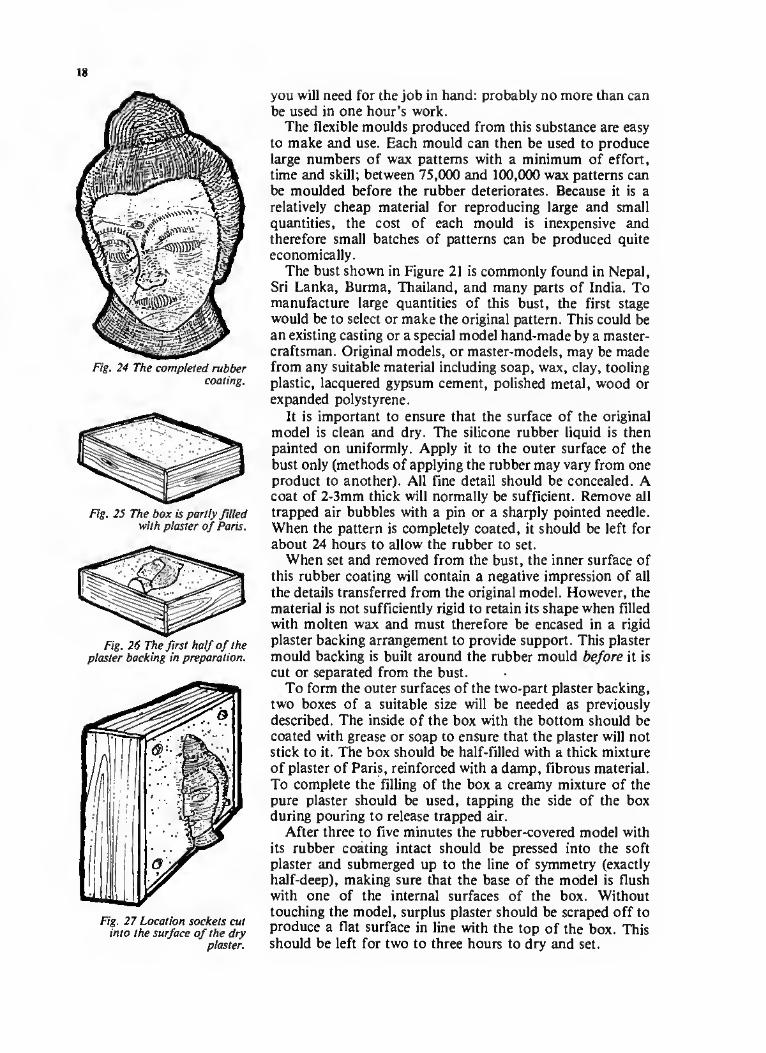
Fig. 24 The completed rubber coating.
Fig. 25 The box is partly filled with plaster of Paris.
Fig. 26 The first half of the plaster backing in preparation.
Fig. 27 Location sockets cut into the surface of the dry
plaster.
you will need for the job in hand: probably no more than can be used in one hour’s work.
The flexible moulds produced from this substance are easy to make and use. Each mould can then be used to produce large numbers of wax patterns with a minimum of effort, time and skill; between 75,000 and 100,000 wax patterns can be moulded before the rubber deteriorates. Because it is a relatively cheap material for reproducing large and small quantities, the cost of each mould is inexpensive and therefore small batches of patterns can be produced quite economically.
The bust shown in Figure 21 is commonly found in Nepal, Sri Lanka, Burma, Thailand, and many parts of India. To manufacture large quantities of this bust, the first stage would be to select or make the original pattern. This could be an existing casting or a special model hand-made by a master- craftsman. Original models, or master-models, may be made from any suitable material including soap, wax, clay, tooling plastic, lacquered gypsum cement, polished metal, wood or expanded polystyrene.
It is important to ensure that the surface of the original model is clean and dry. The silicone rubber liquid is then painted on uniformly. Apply it to the outer surface of the bust only (methods of applying the rubber may vary from one product to another). All fine detail should be concealed. A coat of 2-3mm thick will normally be sufficient. Remove all trapped air bubbles with a pin or a sharply pointed needle. When the pattern is completely coated, it should be left for about 24 hours to allow the rubber to set.
When set and removed from the bust, the inner surface of this rubber coating will contain a negative impression of all the details transferred from the original model. However, the material is not sufficiently rigid to retain its shape when filled with molten wax and must therefore be encased in a rigid plaster backing arrangement to provide support. This plaster mould backing is built around the rubber mould before it is cut or separated from the bust.
To form the outer surfaces of the two-part plaster backing, two boxes of a suitable size will be needed as previously described. The inside of the box with the bottom should be coated with grease or soap to ensure that the plaster will not stick to it. The box should be half-filled with a thick mixture of plaster of Paris, reinforced with a damp, fibrous material. To complete the filling of the box a creamy mixture of the pure plaster should be used, tapping the side of the box during pouring to release trapped air.
After three to five minutes the rubber-covered model with its rubber coating intact should be pressed into the soft plaster and submerged up to the line of symmetry (exactly half-deep), making sure that the base of the model is flush with one of the internal surfaces of the box. Without touching the model, surplus plaster should be scraped off to produce a flat surface in line with the top of the box. This should be left for two to three hours to dry and set.
19
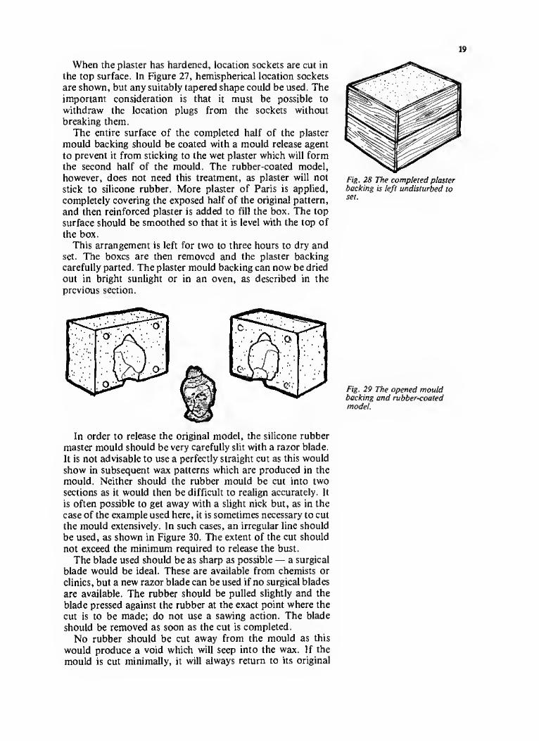
When the plaster has hardened, location sockets are cut in the top surface. In Figure 27, hemispherical location sockets are shown, but any suitably tapered shape could be used. The important consideration is that it must be possible to withdraw the location plugs from the sockets without breaking them.
The entire surface of the completed half of the plaster mould backing should be coated with a mould release agent to prevent it from sticking to the wet plaster which will form the second half of the mould. The rubber-coated model, however, does not need this treatment, as plaster will not stick to silicone rubber. More plaster of Paris is applied, completely covering the exposed half of the original pattern, and then reinforced plaster is added to fill the box. The top surface should be smoothed so that it is level with the top of the box.
This arrangement is left for two to three hours to dry and set. The boxes are then removed and the plaster backing carefully parted. The plaster mould backing can now be dried out in bright sunlight or in an oven, as described in the previous section.
Fig. 28 The completed plaster backing is left undisturbed to set.
In order to release the original model, the silicone rubber master mould should be very carefully slit with a razor blade. It is not advisable to use a perfectly straight cut as this would show in subsequent wax patterns which are produced in the mould. Neither should the rubber mould be cut into two sections as it would then be difficult to realign accurately. It is often possible to get away with a slight nick but, as in the case of the example used here, it is sometimes necessary to cut the mould extensively. In such cases, an irregular line should be used, as shown in Figure 30. The extent of the cut should not exceed the minimum required to release the bust.
The blade used should be as sharp as possible — a surgical blade would be ideal. These are available from chemists or clinics, but a new razor blade can be used if no surgical blades are available. The rubber should be pulled slightly and the blade pressed against the rubber at the exact point where the cut is to be made; do not use a sawing action. The blade should be removed as soon as the cut is completed.
No rubber should be cut away from the mould as this would produce a void which will seep into the wax. If the mould is cut minimally, it will always return to its original
Fig. 29 The opened mould backing and rubber-coated model.

20
Fig. 30 The rubber mould is cut to release the original model.
t
i Fig. 31 The original mode! is
removed and put aside.
Fig. 32 The rubber mould, clamped inside the plaster
backing and ready for use.
shape and if it is left as much as possible in its original state, the wax patterns will be faithfully reproduced in the mould cavity. The bust, which is no longer needed, is discarded as the inner surface of the rubber mould contains an accurate impression of the original pattern.
When the plaster mould backing has been thoroughly dried out and cooled down, the next stage can begin. The now- hollow rubber master-mould is replaced inside the plaster mould .backing and the whole arrangement is clamped together with string or rubber bands or between heavy weights. The assembled mould, which is now a hollow, negative impression of the original model, is ready for the manufacture of a large number of wax patterns of the bust.
The next stage is to melt enough wax to produce the required number of wax patterns. Some molten wax, prepared according to one of the recipes given above, should be poured into the mould; then gently washed around the internal surface before pouring out again. This prepares the surface of the silicone rubber for pattern making. At no stage should the molten wax be unnecessarily agitated as this can cause air bubbles on the surface of the rubber, spoiling the surface finish on the wax patterns. At no point should the wax be overheated. The wax should be poured into the mould again, until it is full to the brim, then left to stand. Tapping the side of the mould lightly should release any air bubbles formed in the wax. If the wax-filled mould was left to stand long enough, it would produce a solid wax pattern considerably more rigid than candle wax. But the aim is to produce a hollow wax impression. To do this, the setting process is interrupted and the unset volume of wax poured out leaving a hollow pattern. The thickness of the walls of this pattern is determined by the length of time the wax is left standing in the mould and can be controlled as it forms by observing the opening through which the wax entered.
As the pattern reaches the desired wall thickness, the remaining molten wax is poured out and the plaster mould backing is opened. The silicone mould, containing the hollow wax pattern, is carefully removed from the plaster backing and placed in a container of cold or cool water and allowed to harden. Once the wax feels sufficiently hard to be handled, the mould and pattern are removed from the water and separated from each other. The mould must then be dried with a clean cloth.
The silicone rubber mould is replaced in its plaster backing, and more molten wax is poured in until the mould is full. The wax is again left until the desired wall thickness has been achieved, then the surplus molten wax is poured out, and the mould and pattern cooled and separated. In this way, large numbers of identical wax patterns can be easily produced with a minimum of skill, with little expense, and in a short time.
When wax patterns are made in silicone moulds, as described above, they are generally more or less complete when removed from the mould. In some cases, however,

21
rather than moulding a one-piece wax pattern, individual parts are moulded in master-moulds and assembled later, allowing for greater variety in product design. Whenever this method is used the individual wax pieces are assembled with heated tools described below.
Tools for shaping and joining wax
Heat in some form is necessary when working with wax and can be provided by a charcoal or wood fire, a gas burner, or an alcohol lamp. Shaping tools for model and pattern¬ making include spatulas, old dental tools with various ends, nails set into wooden handles and hammered into various shapes, patching tools made of heavy wire or rod, and pointed knives. When used with heat, however, they must either be quite long or provided with insulating handles.
The other major item needed when working with wax is warm water, which should soften rather than melt the wax, allowing it to be reshaped and bent with minimal surface stress.
Cutting tools are used to make basic shapes and openings, whereas spatulas are generally used to add wax and develop designs. When joining strips of wax, the tool should be held over the heat for three or four seconds, then placed against the joint-line of the wax strips which melt and fuse together. Wax can also be added to a model in a liquid state by heating it in the spoon-like depression of a spatula, then trailing it on to a previous layer of wax.
Spruing wax patterns
Once the surface of a wax pattern has been satisfactorily smoothed, a wax sprue and a pouring cup has to be added. The sprue should be tapered from top to bottom to reduce the acceleration of the molten metal as it enters the mould. Otherwise, gases could be drawn into the molten metal, producing a porous casting. On the other hand, if metal flow is excessively restricted, solidification may occur before the moulding cavity has been completely filled; this would result in an incomplete casting. These two considerations, along with the dimensions of the final casting, set the upper and lower limits to the size of the sprue. A combined sprue and pouring cup pattern may be made in a plaster of Paris mould.
If the item to be cast has a particularly complex shape or if its weight is unevenly distributed, then wax runners are formed and added to the pattern, as shown in Figure 38. Their function is to carry metal to restricted areas of the casting or to particularly heavy areas, where it might not otherwise flow.
Runners are always relatively thin and few in number; they should be as short as possible and no closer to each other than 10mm. The number of runners will depend on the design and size of the casting, with a heavy item requiring more runners than a delicate one.
Fig. 33 Pouring the wax.
Fig. 34 A sectional view of the mould showing the wax setting.
A Section through rubber mould.
B The wax in contact with the rubber starts to set first.
C Hemispherical location sockets.
D Half of the plaster mould backing.
E Molten wax.
thickness of a wax pattern. A The wall thickness may be
seen and felt at the opening in the top of the mould.
22
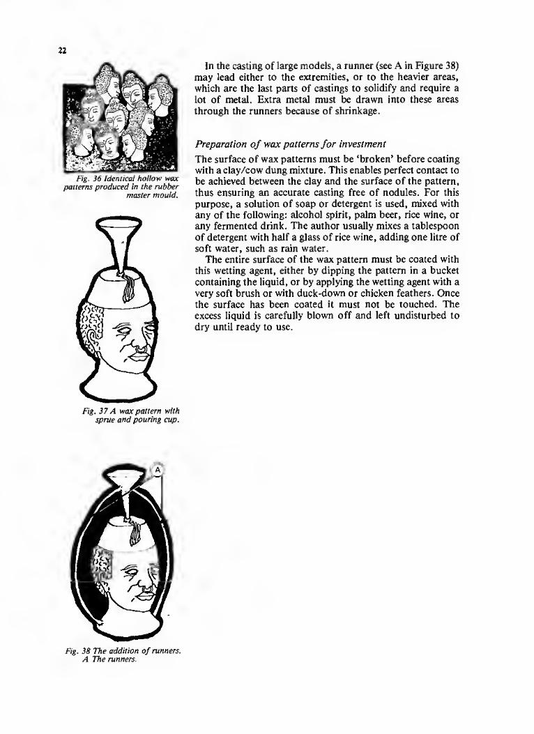
Fig. 36 Identical hollow wax patterns produced in the rubber
master mould.
Fig. 37 A wax pattern with sprue and pouring cup.
In the casting of large models, a runner (see A in Figure 38) may lead either to the extremities, or to the heavier areas, which are the last parts of castings to solidify and require a lot of metal. Extra metal must be drawn into these areas through the runners because of shrinkage.
Preparation of wax patterns for investment
The surface of wax patterns must be ‘broken’ before coating with a clay/cow dung mixture. This enables perfect contact to be achieved between the clay and the surface of the pattern, thus ensuring an accurate casting free of nodules. For this purpose, a solution of soap or detergent is used, mixed with any of the following: alcohol spirit, palm beer, rice wine, or any fermented drink. The author usually mixes a tablespoon of detergent with half a glass of rice wine, adding one litre of soft water, such as rain water.
The entire surface of the wax pattern must be coated with this wetting agent, either by dipping the pattern in a bucket containing the liquid, or by applying the wetting agent with a very soft brush or with duck-down or chicken feathers. Once the surface has been coated it must not be touched. The excess liquid is carefully blown off and left undisturbed to dry until ready to use.
Fig. 38 The addition of runners. A The runners.

23
Chapter 5: Investment mould coatings
In practice, the preparation of clay moulds often involves weeks of work, various ‘mystic’ mixtures, and sometimes rather unsuccessful results. The most widespread method of producing a mould is to coat the wax pattern with several layers of refractory slurry, which involves considerable delays while the mixture dries.
On a recent technical assistance trip to Upper Volta, the author observed one of the fastest and best methods of preparing clay moulds he has ever seen. A mixture of 60 per cent and clay and 40 per cent horse or cow dung is mashed into a soft, compact, butter-like material for covering the mould. All large, hard matter is removed from the mixture by straining through a fine sieve. If absolutely necessary, small amounts of water may be added to help achieve the required consistency. This mixture is then carefully and accurately spread on the wax model in a single coat, as though it were butter. It is then left to dry.
In Papua New Guinea the author developed a variation on this recipe:
Very fine, light-coloured clay 35 per cent Very fine grain husks 30 per cent Cow dung 30 per cent Ash and fine charcoal 5 per cent
Mix these ingredients to the consistency of stucco (or wall- plaster) and then sieve through 40 or 60 mesh, or a doubled fly-screen. Apply as a single coat to the wax pattern.
A basic description of the slurry-coating method now follows; it will be up to the individuals to find out which technique best suits their circumstances and needs.
The first slurry technique involves mixing 70 per cent of fine clay (60 mesh) to 30 per cent dung liquor (the latter is discussed in Chapter 3). Add in 5 per cent, by volume, of finely sieved ash. Mix to a light creamy consistency and sieve through a 60 mesh screen. Apply by dripping on to the wax pattern, while blowing on the surface to remove air bubbles. Spread a thin uniform coat over the model and allow it to dry. Repeat twice to build up thickness.
The other two slurry techniques to be described differ from the first in that they need a backing coat of a thicker mixture. A standard backing-coat recipe is given at the end of this section. (All percentage proportions in these recipes refer to volumes assessed by eye.)

24
Section through wax pattern
Section through mould coating
□ Section through clay core
□ Surface detail
Fig. 39 Three wax patterns coated with the investment
mixture.
Second slurry technique
First mix the following ingredients:
Fine charcoal dust 30 per cent Cow dung 50 per cent Fine ash 20 per cent
Add water to a creamy consistency, and sieve through a 60 mesh, or triple fly screen. Apply as a single drip coat. When this has dried, apply a standard backing coat.
Third slurry technique
Mix powdered sulphur and water to a creamy consistency. Apply as a drip coat. Allow to dry and then apply a standard backing coat.
Standard backing coat
Clay 40 per cent Cow dung 30 per cent Fine ground rice, wheat bran, or other finely ground cereal husks 25 per cent Ash and fine charcoal 5 per cent
Add water to achieve a stucco or wall plaster consistency and plaster over the first coat. Build up evenly to a thickness of approximately 1.5cm to 2cm in order to resist the pressure of molten metal during casting.

25
Chapter 6: Burn-out and casting
When the moulds have dried out fully, they are placed over a hole in the ground with their pouring cups face down. A fire is built over or around the moulds, causing the wax to melt out on to the ground or into a receiving receptacle. This leaves a hollow area in each mould which is the precise form of the wax pattern plus the runners, sprue and pouring cup, if used.
The wax-free moulds are removed from the burn-out pit and rubbed with the clay/dung mixture to seal any cracks caused by the heat. They are then returned to the burn-out pit, again with their pouring cups facing downwards, and are heated by a slow fire to ensure complete penetration by the heat in preparation for casting. Meanwhile the metal is placed in a crucible and melted in a furnace. Existing furnaces utilize a variety of bellows or hand-operated forced-air blowers or electric forced-air blowers.
When the moulds and metal are judged ready for pouring (when they are glowing red with heat), the moulds are removed from the fire with tongs and placed upright in soft earth or sand. The crucible is then removed from the forge fire with tongs and the metal poured through the pouring cups until all the moulds are filled. Any molten metal remaining in the crucible is poured away onto soft earth and salvaged for future use.
Fig. 40 Sectional view of hollow mould.
Burn-out oven with burner assembly, Colombia.
Fig. 41 The moulds are filled with molten metal.
26
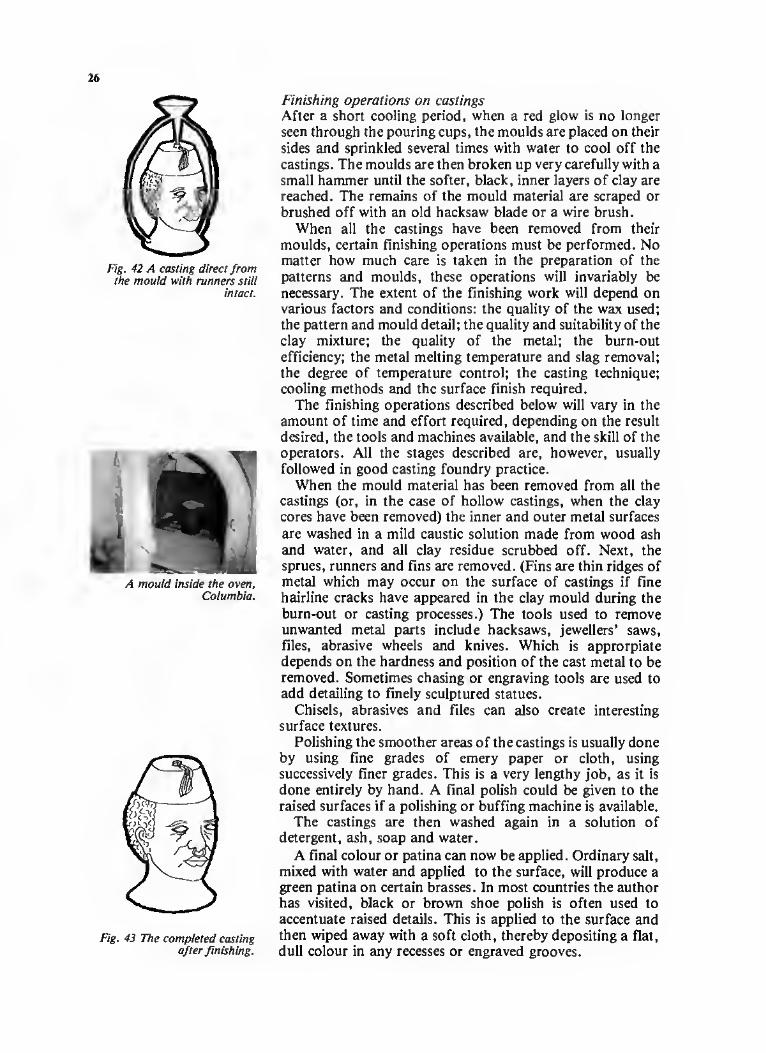
Fig. 42 A casting direct from the mould with runners still
intact.
A mould inside the oven, Columbia.
Fig. 43 The completed casting after finishing.
Finishing operations on castings After a short cooling period, when a red glow is no longer seen through the pouring cups, the moulds are placed on their sides and sprinkled several times with water to cool off the castings. The moulds are then broken up very carefully with a small hammer until the softer, black, inner layers of clay are reached. The remains of the mould material are scraped or brushed off with an old hacksaw blade or a wire brush.
When all the castings have been removed from their moulds, certain finishing operations must be performed. No matter how much care is taken in the preparation of the patterns and moulds, these operations will invariably be necessary. The extent of the finishing work will depend on various factors and conditions: the quality of the wax used; the pattern and mould detail; the quality and suitability of the clay mixture; the quality of the metal; the burn-out efficiency; the metal melting temperature and slag removal; the degree of temperature control; the casting technique; cooling methods and the surface finish required.
The finishing operations described below will vary in the amount of time and effort required, depending on the result desired, the tools and machines available, and the skill of the operators. All the stages described are, however, usually followed in good casting foundry practice.
When the mould material has been removed from all the castings (or, in the case of hollow castings, when the clay cores have been removed) the inner and outer metal surfaces are washed in a mild caustic solution made from wood ash and water, and all clay residue scrubbed off. Next, the sprues, runners and fins are removed. (Fins are thin ridges of metal which may occur on the surface of castings if fine hairline cracks have appeared in the clay mould during the burn-out or casting processes.) The tools used to remove unwanted metal parts include hacksaws, jewellers’ saws, files, abrasive wheels and knives. Which is approrpiate depends on the hardness and position of the cast metal to be removed. Sometimes chasing or engraving tools are used to add detailing to finely sculptured statues.
Chisels, abrasives and files can also create interesting surface textures.
Polishing the smoother areas of the castings is usually done by using fine grades of emery paper or cloth, using successively finer grades. This is a very lengthy job, as it is done entirely by hand. A final polish could be given to the raised surfaces if a polishing or buffing machine is available.
The castings are then washed again in a solution of detergent, ash, soap and water.
A final colour or patina can now be applied. Ordinary salt, mixed with water and applied to the surface, will produce a green patina on certain brasses. In most countries the author has visited, black or brown shoe polish is often used to accentuate raised details. This is applied to the surface and then wiped away with a soft cloth, thereby depositing a flat, dull colour in any recesses or engraved grooves.

PART 2: CONSTRUCTION TECHNIQUES

THIS PAGE IS BLANK but this is not a printing or scanning
fault and no content is missing.

29
Chapter 7: Preparing clay mixtures
The quality of clay-bearing soils varies from country to country, and from village to village. The author has found that established local casters already use a clay which is quite satisfactory, and that is the one to stick with. The lighter the colour of the soil, the better the refractory characteristics that can be expected. It should preferably contain a small percentage of mica. An ideal casting clay would contain silica, gypsum, carbon, iron oxide, copper and kaolin.
The principal characteristics of a good casting clay include the capacity to withstand temperatures of more than 1,000°C, the flexibility to respond to extreme heating and cooling without cracking or breaking, and the ability to reproduce a smooth and detailed surface on molten metal. It must also be able to withstand the shock following the sudden introduction of molten metal, and physical shocks resulting from accidental knocking during handling.
If a suitable clay has not been identified by local casters, brick-makers or potters, then it will be necessary to search systematically the locality and analyse the soils (see the section on ‘Choosing a suitable clay’ later in this chapter).
Cow and horse dung
When dealing with technical assistance problems in developing countries it is all too easy to overlook basic materials which are available locally. The importation of chemically perfect materials for the reproduction of castings is generally an expensive solution, and leaves the local operation dependent on imports. The author has spent many years searching for locally available natural materials which may be used as clay-binding agents. The best, and most successful material which he has found, and which is available in every village, is cow dung. After all, many developing countries have used cow, horse and donkey dung for centuries, mixed with clay to form the mortar and outer coating of mud huts.
Cow, horse and donkey dung contain certain properties that greatly help the caster. Furthermore, dung is found everywhere, and the fresher the better. The author has used cow dung in Indonesia, Malaysia, Nepal, Thailand, Ghana, Upper Volta, Papua New Guinea, Lesotho, Swaziland and Colombia, and has had no trouble at all with different types.
Sieving and preparing the day, Ghana.

30
from different breeds or feeds, nor from lean or fat animals. Dung of almost any description acts as a binding agent. It also possesses the capacity to retain its flexibility when heat- dried, and does not shrink appreciably. These characteristics make it ideal for casting clays, and for use as an oven and furnace mortar, and lining material.
In all the author’s recent consultancy work, cow dung mixed with clay has been used to form casting moulds and cores; as construction mortar in oven and furnace building; and mixed with graphite to make crucibles. In these capacities the mixture coped very well with temperatures up to 1,500°C, and also with incidental thermal and physical shocks.
A basic mixture
The dung is first mixed in a large container. It is easier to get into the container with bare feet, not unlike a wine presser, and knead the material. For people who find this offensive, or where animal dung is suspected of transmitting parasites or diseases, hand-manipulated pressing tools can, of course, be used. Vaccination against tetanus is also a very necessary precaution. If the dung is dry, add water to bring it to the required liquid state. When all the fibrous material has dissolved, and the kneading has reduced the dung to a thick creamy consistency, it is ready for use. It is now referred to as dung-liquor.
Mix the dung-liquor with an equal volume of fine clay. It is best to prepare enough of the clay/dung-liquor mixture to last a week. This then forms the basic clay mixture, which can be used as construction mortar and for making casting-cores.
If the smell is particularly offensive, a rub with lemon leaves, or lemon grass, will take care of the unpleasantness. The smell is usually less noticeable after about 15 minutes.
The next state is to mix in either rice husks or spent grain. Again, these readily available materials are found in all developing countries and cost practically nothing. The addition of this material binds the clay and dung-liquor mixture together, and the small amount of oil in the husks or
Making a test of clay quality, Papua New Guinea.

grain improves refractoriness and reduces the tendency of the mix to expand when heated. As a general purpose mix, add the husks or spent grain in the proportion of 30 per cent of the clay/dung-liquor mixture by volume. This is then kneaded and beaten to the consistency of butter and left for one day to settle and mix properly.
Furnace and oven lining mixture
For the mortar to line the oven and furnace use unmilled husks or grain, mixed into the 50-50 mixture of clay/dung liquor, the proportion being 20 per cent by volume. The mixture is then left to stand overnight prior to use. This gives the grain or husks a chance to absorb the water from the mixture and become an integral part of it. The following alternative mixture could also be used:
Dung-liquor 30 per cent Fine clay 30 per cent Wheat bran 30 per cent Fine sharp silica sand 10 per cent
Mix with water to a soft butter consistency. Add 30-40 per cent fly-screen sieved ‘grog’ (grog is made by crushing, clay building bricks into dust).
Choosing a suitable clay
If you are unfamiliar with procedures for identifying clay, speak first to a local brick-maker, potter or caster. No doubt he or she will already have tested local soils for their clay/sand/silt content. On the other hand, if you cannot obtain the information you need, you will have to locate a suitable clay yourself. This is not as difficult as it may seem. Do not be too concerned with the chemical composition. Man has been making clay pots far longer than chemi'ts have been in existence, and workable clay mixtures have outlasted opinions about them.
Location and test-firing
It is advisable to look for clay in and around river beds and quarries. Keep in mind that a light-coloured soil usually contains a higher percentage of clay and has the best refractory characteristics. Ideally, a soil with a 30 to 40 per cent clay content is recommended, but soil with as much as 60 per cent clay can be used, adding sand to reduce the clay content. The lowest clay content which the author has used successfully was 20 per cent. Try to avoid silty soils and those with no clay content, such as volcanic ash and sandy soils, since these will have little or no ability to hold together. Once a likely looking soil has been selected, make a small brick, dry it in bright sunlight for three to six days, depending on climatic conditions, and then fire it. If the fired brick does not fall apart or crack up, and has a normally hard surface, the soil proably contains sufficient clay for casting.

32
_ ) Clay
:V-:Sand
__ -
Fig. 44 A typical shake-test result.
Treading the cow-dung mixture, Papua New Guinea.
Shake lest
To discover the approximate percentage of clay in the soil sample, carry out a simple shake test. For this purpose you will need a glass jar, about 10-15cm high, with a screwed or tight-fitting lid. Place enough soil, in crushed form, in the jar to fill the bottom 2-3cm. Add water until the jar is about two- thirds full. Then shake the jar until all the soil has dissolved, and set the jar down at eye level where it will not be disturbed. After one day, observe how the mixture has settled into distinct layers. The uppermost layer is the silt content. The sand will be at the bottom and the middle layer will be clay.
Other bits and pieces of straw, rock, twigs and so on, may be present, and may be peculiar to the local area where the soil came from. It would be wise to dig down below the surface layer when collecting soils, and also to select samples from various locations.
When the soil in the jar has settled into layers, as indicated above, measure the total height of the contents, and the height of the band of clay. Dividing the first figure by the second gives the approximate proportion of clay in the soil sample. An example is shown in Figure 44.
Palm wetting test
The palm wetting test is another method of testing the clay content. Take a lump of light-coloured soil in your hand. Smooth, wet and knead it until it reaches a uniform consistency of hard butter. Holding this smooth lump of soil on one of your palms, coat it with water, rubbing across the surface with your other wet hand. Then slowly close your hand around the soil. Open your hand and see if the soil has a shine on its surface. If the shine is evident, and does not fade rapidly, your soil probably has a high enough clay content. On the other hand, if the shine disappears, this would indicate a high sand or silt content, and the sample would not be sufficiently ‘sticky’ to bind the grains of sand together.
If the clay content is very high, you will get a large amount of shrinkage and cracking during Firing. To correct this problem, add sharp silica sand, not sea-sand, because it contains salt. (If sea-sand is the only type available, then wash it thoroughly in clear fresh water.)
Coil test
The coil test involves rolling the soil sample into a cylinder, approximately one inch thick by four inches long. Hold the coil at one end, between thumb and finger, and let the other end sag towards the ground. If the coil breaks, the soil probably has an unacceptably high silt and/or sand content. On the other hand, if the coil bends and does not break, the clay content will be sufficient.

Shrinkage and cracking
Shrinkage is prevalent in all clays which are heated, and should not present any major problems if clays are selected by use of the above tests. Shrinkage is also minimized by the addition of cow dung and bran, as explained above. Minor cracking which occurs, and is to be expected, during the heating or drying of clay mixtures can be easily repaired by filling the cracks with clay/dung mixtures.

34
line.
Fig. 46 Plan view of brick base.
A completed oil-drum crucible furnace, Colombia.
Chapter 8: Constructing a crucible furnace
The current methods used in the Third World of casting metal by means of open-pit charcoal-fired melting present a number of problems resulting from the lack of sufficient control over the melting process. The two most obvious problems are that the molten metal absorbs carbon from the oxidizing charcoal fire and that the crucible is unevenly heated, producing a melt of varying temperatures. Also the amount of metal which can be melted in an open-pit fire is uneconomically small.
The furnace described in this chapter is designed to melt 25kg of bronze at one time. Naturally, a smaller quantity can be melted, though it is less economical. The furnace is also designed to be used with bottled-gas fuel. Even in areas of the world where wood is plentiful, charcoal is still expensive. The amount of charcoal required to melt 25kg of brass, bronze or aluminium, is more costly in many countries than an equivalent amount of bottled liquid petroleum gas (LPG or butane). Despite the increasing unpopularity of recommending the use of fossil fuels in developing countries, the author suggests that butane be used if it is readily available and cheap. The heat obtained from butane gas, approximately 120,000 BTU per cubic metre, produces a quicker and hotter melt that other available fuels, and it is certainly the cleanest casting fuel.
If bottled gas is not available, the furnace can be fired by kerosene, old engine oil or diesel fuel. Slight modifications

FURNACE CONSTRUCTION MATERIALS — BASIC LIST FOR A
GAS-FIRED SYSTEM
35
Material Qty/Length/Weight Use
45 gal. oil drum 1 Furnace body
5-6cm water pipe 3m Rising-butt hinge and mixing chamber
Tight-fitting pipe or rod to fit inside water pipe 1.5m Core-pin of rising-butt hinge
Soft copper tubing (6-10mm internal diameter) 2m Pipe connection from gas to mixing
chamber
Bricks 100 approx Furnace lining material
Heavy-duty wire mesh lsq m Supporting top lining
Clay/dung-liquor mix 50kg approx Mortar and insulation
Gas valve 1 Controlling gas supply
Mild steel flat-bar (50mm x 4mm) Miscellaneous metal and tools
3m As required
Supporting hinge assembly As required
Use of oxy-acetylene gas-cutting tools/or any means to cut oil drum.
Use of an electric arc-welding set.
A Makita fan-blower Type 4014B, or similar blower may be purchased, fabricated or improvised.
Bottled LPG Butane gas with high-pressure valve.
would, however, need to be made to the fuel supply system, especially the burner. At the end of this chapter, a description is given of an alternative burner designed for use with old engine-oil discarded from gear-boxes. This is much cheaper than using bottled butane gas. However, it takes much longer to reach the required melting temperature, and the oil does not burn as cleanly as gas.
The melt furnace is used to melt virgin or scrap metals, and to produce alloys for casting. The construction is based on a 45 gallon oil drum and is illustrated in Figure 48. The drum is lined with bricks, which are then coated with a clay/dung mixture described in Chapter 7. The gas is mixed with forced air in a 6cm diameter mixing chamber. The air should be supplied by a ‘Makita 4014 B’ fan blower/duster, or similar product with a fan and operating at about 12,000rpm.
The metal to be melted is placed in a crucible which is loaded into the melt chamber. The furnace is then closed to allow the temperature to build up, the model shown here can reach temperatures greater than 1,500°C. Temperatures are read from the colour of the glow which can be seen through the exhaust hole in the top of the furnace (see Table on page 36). For safety reasons, this is done by placing a mirror indirectly above the exhaust, rather than trying to look directly into the exhaust hole.
The list of materials required for the construction of the furnace shown at the top of this page may need to be modified from one locality to another. Considerable flexibility of approach may be required in many situations,
Section through brick
Section through mortar
n Surface detail
Fig. 47 Half-section through drums, showing brick-and- mortar base.

36
COLOUR GLOW/HUES OF METALS AT VARIOUS DEGREES OF TEMPERATURE
Temperature Colour (°C)
Barely visible 630 Visible 675 Dull red 775 Dark red 850 Bright red 990
Temperature Colour (°C)
Cherry red 1050 Orange 1150 White 1200 Bright white 1500
Fig. 48 General arrangement of a furnace.
A Furnace base utilizing bottom two- thirds of oil drum.
B Support bricks to reduce heat losses through ground.
C Brick and mortar floor. D Hinge core-pin on which the rising-
butt hinge revolves. E Base section of rising-butt hinge. F Wire mesh to retain drum-top lining. G Metal straps to support weight of
bricks. H Brick and mortar lining. J Opening /closing handle. K Furnace lop — upper one-third of
oil drum, with lid intact.
L Furnace exhaust. M Furnace-top support straps. N Upper section of rising-butt hinge. P Crucible chamber. Q Furnace wall-lining. R Gas-bottle control valve. S High-pressure valve — optional. T Liquid petroleum gas (LPG) bottle. U Gas supply-tube. V Mixing chamber for gas and air. W Fan blower. X Quick shut-off valve. Y Air-pressure control plate.
C

37
and any material which is not available locally will require an appropriate substitute.
Construction
The bricks are first soaked in water for 12 to 24 hours before they are needed. (See note on bricks at the end of this chapter.) The 45 gallon oil drum should be in good condition, and should preferably have the bottom and top intact. Begin by cleaning and drying the drum. Then, using the oxy- acetylene cutting-torch (or other cutting equipment) cut off the top one-third of the drum, just below the top reinforcing bead.
The base of the drum is then lined with bricks and mortar. Begin by putting in a 2cm thick floor of clay/dung-liquor, mixed according to one of the recipes given in Chapter 7. The consistency should be that of a soft butter-like mortar. The next layer consists of bricks, which are laid face-to-face in the bottom of the drum. A mortar seam of not more than 0.5cm connects the rows of bricks. The gaps left after including all possible whole bricks should be filled with solid, single pieces of brick, specially shaped to fill the gaps. The brick base is then coated with a layer of the mortar mixture to a thickness of l-2cm and finished off so that it is smooth and flat.
Before the wall lining of the furnace can be built up, a hole of the right size must be cut in the side of the drum, just above the brick-and-mortar base, to allow a 6cm diameter pipe to enter the furnace. The pipe is then loosely inserted through the hole, and the first layer of the wall lining built around it. The first row of bricks is laid so that the corners touch each other, as shown in Figure 49. The almost triangular spaces left between the bricks should be filled with specially shaped pieces of solid brick. This will keep heat losses to a minimum.
The next row of bricks should overlap the joint-lines of the first row, with a maximum 0.5cm layer of mortar between rows. The overlapping of one layer of bricks with another, with a 0.5cm layer of mortar between rows, is continued to within a few centimetres of the top edge of the drum base. The gaps in each layer of bricks must be filled with triangular pieces of solid brick.
The lining of the furnace with a clay mixture can now begin. First mix additional brick/grog to the basic mortar, in the proportion of approximately 20 per cent by volume. Then, starting at the bottom, pack this clay mixture into the wedge-shaped recesses left by the overlapping of the brick rows. When this is finished, a second layer of mortar with fine grog should be applied to produce a round, smooth lining from the bottom to the top of the drum base.
The top inside edge of the lining should be rounded into a small smooth curve, as shown in Figure 53, as a sharp edge would be easily broken and would impede the flow of heat. After allowing a few hours for drying, smooth the lining with a damp sponge. Complete the smoothing with the palm of your hand.
Fig. 49 Plan view of first row of wall bricks, showing the pipe inserted through the drum wall.
Fig. 50 Filling the spaces between bricks.
Fig. 51 Plan view of overlapping bricks.
Tidying the edge of the oil drum.

38
Fig. 52 Half -section of drum base, showing first two rows of
overlapping bricks.
Fig. 53 Section through drum base, showing completed brick-
and-mortar lining.
Fig. 53
Preparing the furnace top
To prepare the top one-third of the drum — the section which was cut off — a 12cm exhaust hole is first cut out in the centre of the drum lid. The drum top is then inverted on its lid on the ground. A 1cm layer of mortar is laid inside, and followed by a layer of bricks. Stand the bricks on end for maximum height, and join them with a minimum amount of mortar. Take care not to block the exhaust hole.
The gaps left between the whole bricks and the wall of the drum top are now filled with specially shaped pieces of brick. The exhaust hole is then rounded out with mortar into a cone, tapering towards the lid.
Next, four mild steel flat-bar straps are welded or bolted into place, again making sure not to obstruct the exhaust hole. These straps will take the weight of the bricks when the top is eventually inverted over the base of the drum.
Fig. 54 Plan view of brick-filled drum top with conical exhaust
hole.
A Whole bricks stood on end. B Mortar seams between
bricks. C Shaped part-bricks stood on
end. D Mortar seam between bricks
and drum wall. E Drum wall. F Pieces of brick used to fill
small gaps. G Exhaust hole through drum
lid. H Conical exhaust hole formed
from mortar.

39
The remaining space is then packed with mortar and pieces of broken brick, to within 2-5cm of the top edge of the drum top. Heavy-duty wire mesh is laid into the mortar and tack- welded or bolted to the inner surface of the drum wall. A fine layer of mortar is then pressed into place and smoothed level with the top edge of the drum top.
The conical exhaust hole is again smoothed and a small ridge of mortar built out on to the metal lid (see Figure 58). The purpose of this ridge is to protect the metal lid from direct heat, which would burn it.
Fig. 58
Drying the furnace
It is very important to line both sections of the furnace in one day, otherwise major internal cracking could develop at the continuation line when the mortar dries out.
Fig. 55 Half-section through drum top, showing brick-and- mortar lining and mild steel retaining straps.
Fig. 56 Wire mesh in place to retain lining material.
Fig. 57 Section through drum top, showing the completed lining.
Fig. 58 Reinforcing plates and hinge base welded into place and core-pin inserted.
The finished lid.
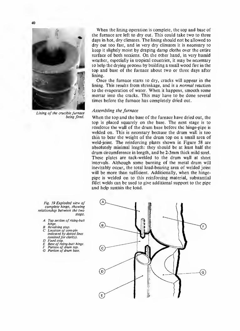
40
When the lining operation is complete, the top and base of the furnace are left to dry out. This could take two to three days in hot, dry climates. The lining should not be allowed to dry out too fast, and in very dry climates it is necessary to keep it slightly moist by draping damp cloths over the entire surface of both sections. On the other hand, in very humid weather, especially in tropical countries, it may be necessary to help the drying process by building a small wood fire in the top and base of the furnace about two or three days after lining.
Once the furnace starts to dry, cracks will appear in the lining. This results from shrinkage, and is a normal reaction to the evaporation of water. When it happens, smooth some mortar into the cracks. This may have to be done several times before the furnace has completely dried out.
Assembling the furnace
When the top and the base of the furnace have dried out, the top is placed squarely on the base. The next stage is to reinforce the wall of the drum base before the hinge-pipe is welded on. This is necessary because the drum wall is too thin to bear the weight of the drum top on a small area of weld-joint. The reinforcing plates shown in Figure 58 are absolutely minimal length: they should be at least half the
drum circumference in length, and be 2-3mm thick mild steel. These plates are tack-welded to the drum wall at short intervals. Although some burning of the metal drum will inevitably occur, the total load-bearing area of welded joint will be more than sufficient. Additionally, when the hinge- pipe is welded on to this reinforcing material, substantial fillet welds can be used to give additional support to the pipe and help sustain the load.
Fig. 59 Exploded view of complete hinge, showing
relationship between the two stops.
A Top section of rising-butt hinge.
B Revolving stop. C Location of core-pin
indicated by dotted lines (omitted for clarity).
D Fixed stop. E Base of rising-butt hinge. F Portion of drum top. G Portion of drum base.
Lining of the crucible furnace being fired.

41
Fig. 60
Fig. 60 Plan view of rising-butt hinge.
A Core-pin. B Fixed stop. C Drum top. D 6cm water pipe. E Revolving stop. F Fillet-welded joints.
Fig. 61 Top section of hinge and reinforcing plates welded to drum wall.
A rising-butt hinge-angle must now be cut on the 6cm diameter water pipe. Take two metres of the pipe and cut off a section equal to the height of the furnace base. This cut should be made at an angle of 30°. The pipe is then welded to the reinforcing plates on the drum-base, angled surface uppermost, in the position shown in Figure 58. When the base of the hinge and reinforcing plates have been welded in place, the core-pin is inserted. The core-pin should be closely fitted to the inside diameter of the 6cm diameter water pipe, with not more than 1mm of slack, or clearance.
As shown in Figure 59, the hinge must also have two stops welded on, in such a way that the furnace can be opened just over half a revolution before the stops engage. This ensures that the furnace can be left in the open position without having to be held open.
When the top section of the hinge is slid onto the core-pin, the angled surfaces must be adjusted until they are in perfect contact with each other. The hinge top and drum top are then welded together in the same manner as the base, but using only two reinforcing plates.
Next, mild steel support straps and an opening handle are welded to the furnace top. Because of the design of the hinge, the drum top can now be swung open 200°, or just over half a revolution, and it will remain open. The rising action of the hinge also ensures that no friction occurs between the clay surfaces of the two sections of the furnace; major friction could break up these surfaces. The hinge will, of course, require occasional lubrication with a heavy grease or wax to reduce friction.
Fig. 62 Drum top support straps and opening handle welded in place.

42
Fuel supply arrangement
Figure 63 shows, in plan view, the relative positions of the furnace, the fan and the LPG bottle. The gas bottle is always located outside the workshop, separated by a heavy, thick safety wall, so that it is protected from the heat of the furnace, the burn-out oven and any molten metal being worked openly. Keep it away from children’s play areas and areas where people pass or congregate.
Increase
Fig. 64 Air-pressure control plate.
A Pressure control plate. B End view of 6cm pipe.

43
Fig. 65 Gas pipe entry detail. A Copper gas supply tube. B Brazed joint. C Section through pipe. D Pressure control plate. E Fan blow pipe.
The fan is located close to the furnace, with its blow-pipe inserted in the end of the mixing chamber. However, the electrical lead of the fan should be well insulated and either buried in a channel in the floor, or strung across the ceiling until it is directly above the fan.
An auxiliary high pressure gas valve is provided on the fuel supply pipe near the mixing chamber for maximum control and speedy shut-off. The normal low pressure regulator used to reduce the gas pressure for domestic purposes has to be replaced by a high pressure valve, as the low pressure regulator will not deliver enough gas to the furnace.
Between the blow-pipe of the fan and the entry point of the gas supply pipe, the mixing chamber is provided with a mild steel control plate, which can reduce or increase the air pressure.
The hole through which the gas-tube enters the mixing chamber is drilled at an angle, as shown in Figure 65.
Before you ignite the gas always check for gas leaks at all
An oil-drum crucible furnace, with the lid slung to one side and the crucible to the right, Colombia. (Note the pre-cast ingots ready, on the right.)

44
Fig. 66 Oil-fired furnace system.
A Oil burner connected to furnace.
B Fan blower. C Container for filtered oil. D Hand pump for lifting oil to
roof top. E Roof-mounted oil-delivery
drum. F Oil-delivery hose. G Furnace.
A furnace blower, Papua New Guinea
points of assembly. Even the slightest leak is potentially dangerous — don 7 take chances.
The safest way of lighting and turning off the furnace is as follows. First, switch on the fan and adjust the pressure plate for a low pressure. Next, light a ball of paper and place it in the crucible chamber of the furnace. Only then do you open the gas valve. When the gas ignites in the crucible chamber, the air pressure can be adjusted as required. At the end of the melting operation, turn the gas off first at the main supply, then at the intermediate valve, then finally at the mixing chamber valve. This will ensure that no gas is left in the supply tube and no leaks are present. Then reduce the air pressure slowly until it is fully off.
Alternative oil-fired system
In situations where bottled gas is not available or too costly, an alternative fuel must be found. It is often possible to obtain used engine oil from lubrication systems for little or no cost. This fuel is not as efficient as butane, but the longer time taken to reach the melting point of metals is not likely to be a problem in most situations.
Figure 66 shows the main features of an oil-fired system

45
which the author developed in Papua New Guinea. The filtered oil is poured into a clean oil drum which has a hand pump mounted on its lid. From here it is pumped through a flexible hose to a roof-mounted drum which has an on/off supply tap near the base. (All three containers used in this system are 45 gallon oil-drums.)
The oil is fed under the pressure of gravity to the burner, where it is vapourized by air from a blower fan. The oil flow can be adjusted by opening or closing a simple valve, such as a domestic gas-tap. The air pressure is controlled by the same type of pressure control plate used on the gas-fired system outlined above.
The construction of the burner is shown in Figure 67. The pipework consists of a 50cm length of 6cm diameter water pipe, with a 90° elbow joint. The burner nozzle is a 6cm to lcm pipe reduction bell adaptor.
The oil is delivered to the nozzle by a copper tube of about 8-10mm diameter, which is connected to a gas-tap by a compression coupling. The delivery end of the copper tube
Fig. 67 Oil burner construction.
A 6cm to lcm reduction bell pipe adaptor used as nozzle.
B Oil-delivery pipe (8- 10mm copper tube).
C 6cm diameter 90° elbow joint.
D Pipe support bracket (mild steel).
E Compression coupling. F Oil tap (normal domestic
gas-tap). C Washer brazed to mounting
bracket and damped to tap. H Clamp-nut holds washer and
hose-end coupling in place. J Hose-end coupling. K Oil-delivery hose. L Tap-unit mounting-bracket. M Air-pressure control plate. N Air inlet pipe. P Open end of pipe admits
blow-pipe of blower fan.

46
Fig. 68 Plan view of assembled oil burner and section through
furnace inlet port.
A Mortar ridge around inlet port.
B Tapered inlet port through wall-mortar.
C Paraffin-soaked burning rag.
D Wall-mortar. E Wall bricks. F Furnace base. G Paraffin-soaked rag burned
under nozzle. H Burner mounting arms
welded in place. J Oil-delivery hose damped to
coupling.
must be reduced by careful hammering into a 1mm diameter opening. (This can be done by hammering the end of the copper tube to form a sealed joint around a 1mm diameter nail or pin, and then removing the nail or pin.)
The 6mm gap between the 1mm delivery hole in the copper tube and the face of the delivery nozzle can be adjusted for improved performance by screwing the reducing nozzle in or out.
A large washer is clamped to the left side of the tap by a suitable nut, which also holds a hose-end coupling in place. The washer is brazed to one end of a mounting bracket, as shown in Figure 67. The other end of the bracket is brazed to the elbow joint. The copper tube passes through a drilled hole in the other arm of the bracket, and then through a drilled hole in the elbow joint to within 6mm of the nozzle outlet- port. This is shown in Figure 67.
Figure 68 shows a plan view of the burner and a section through part of the furnace wall. The oil-delivery hose has been connected to the hose-end coupling; and the burner has been secured in position by welding two mounting-arms to the elbow joint and the furnace wall. The free end of the burner, into which the fan blow-pipe is inserted, is not shown.

47
The inlet port in the furnace wall, which admits the flame from the burner nozzle outside, is tapered as shown in Figure 68. A small ridge or lip of mortar is built up around the outside of the port to protect the metal wall from the high temperature of the burner flame. The function of the taper on the inlet port, combined with the shape of the burner nozzle, is to suck air into the furnace from the atmosphere.
Before the burner can be lit, the nozzle and inlet port must be pre-heated for about 15 minutes. This is done by burning paraffin-soaked rags beneath the burner nozzle and inside the furnace, near the inlet port.
When the nozzle and inlet port have been heated, the oil tap is opened slightly to allow a small stream of oil to pass. Then, minimal air pressure is applied, so that a stream of oil vapour and air is delivered to the burning paraffin-soaked rag in the furnace base. When the vaporized oil ignites, the oil- flow and air pressure can be gradually increased to maximum by small increments. The efficiency of combustion increases when the oil has been burning for some time, thus allowing the oil flow to be reduced. The air pressure, however, has to be maintained at its maximum.
Borax lining for a furnace
When the fuel supply has been organized, the furnace is ready for its final lining, which is a glassy, refractory surface. This is achieved by burning a borax flux in the crucible chamber.
General purpose flux used for metal preparation prior to castings: Salt 1kg, Borax 1kg, Boric acid1 100kg.
Add in one pulverized Coca-Cola or Pepsi-Cola bottle (used because of chemical stability and World Manufacturing Standard) and mix uniformly. Throw approximately two handfuls of this flux into the furnace when it reaches a red heat. The fumes thus produced cause the glazing of the inner surface of the crucible chamber and the exhaust hole.
After about 15 minutes throw in two handfuls of borax. The final lining is now complete. When it occasionally needs to be renewed, two handfuls of borax should be thrown into the red-hot furnace. (Use it sparingly; make major repairs with clay/dung mixture.) The furnace is now ready for use.
Before the crucible is loaded in, place two bricks in the base of the furnace. These should be covered with charcoal dust to prevent adhesion or sticking to the base of the crucible during the melting operation.
Note on safety precautions
It would literally be playing with fire to introduce a furnace into a developing country without emphasizing the need for safety. The concept of a work-place being out of bounds for casual visitors is a totally Western idea. Casting shops in
'Anyone can make boric acid for the general purpose flux. Simply dissolve borax in 10 per cent sulphuric acid. Allow to recrystallize by evaporation and then pulverize the crystals.
A completed oil-drum crucible furnace.
Trampling clay for the furnace lining, Ghana.

48
developing countries are often swamped by smiling, laughing, playing children, too numerous to count, not to mention friends, wives, goats, sheep, cows and donkeys. In the interest of safety it is important to limit movement in a casting area.
Combustible fuels must be carefully stored, and all electrical wires properly installed. If gas is used, the bottles must be outside the building, behind a safety wall. If any explosive fuel is used, no naked flame should be allowed nearby.
Safety involves thinking ahead, and the introduction of any new technology demands that thought be given to possible dangers which it might present to its users and their visitors.
*
The preparation of refractory bricks, Ghana.
Note on bricks
On some occasions the author has used special refractory bricks to line the furnace, but he has recently found that this expensive material, which is not always readily available, is not necessary. Standard red building bricks are quite adequate; indeed, the worst quality bricks for building purposes often have the best refractory characteristics, possible because of their spongy, sandy quality, and are therefore more suitable for furnace and oven construction.
If red bricks are not available, then it should be easy to have perfectly adequate bricks made locally, using a sandy clay and wooden moulds. When the moulded bricks have dried out in the sunshine, they can be fired in a makeshift kiln.
The following method of brick-making is recommended.
Brick-making mixture: Well-kneaded fine clay 70 per cent; Fine grog or sand' 30 per cent.
Mix the above materials with water, and thoroughly knead to a soft butter consistency. Press into brick moulds; remove and allow to dry for approximately five days. Finally, fire them in a makeshift kiln for about six hours at a temperature of at least 650°C.
Always make an extra 300 to 400 bricks, to allow for breakages during firing and use. One hundred bricks will also need to be stored for the re-lining of the melt furnace after approximately 50 firings.
'To make bricks for furnace-lining use fire-brick grog, which is simply crushed fire-bricks. For the bricks used to build the burn-out oven, described in the next chapter, use sharp silica sand.

49
Chapter 9: Building a burn-out oven
The burn-out oven is used to melt wax out of the clay moulds, and to heat the moulds to a suitable casting temperature. It also removes all moisture from the clay mixture, thus hardening it and producing moulds of a low- fired ceramic quality.
The oven is so constructed that a uniform heat is transmitted to all parts of any number of moulds placed inside. Provided the oil, gas, charcoal or wood fire in the base of the oven is adequately fed and properly ventilated, an operating temperature of about 800°C can be achieved (if necessary even higher). The heat is controlled by increasing or decreasing the opening of the draught doors and the draught damper in the chimney, or by air/fuel control.
Moulds usually remain in the oven for four to six hours, at which time they should be completely burned out. When a bright red colour can be seen at the pouring cup opening they are judged ready for pouring.
The base of the melt-out chamber is approximately 2m by 1.2m, which will accommodate between 40 and 50 small moulds, depending on their precise size.
The list of construction materials given below is a guide only, and design and construction details may need to be greatly modified from one situation to another.
Figure 69 is a general arrangement of a burn-out oven designed by the author and built in Nepal, Ghana and Colombia, with variations in size only. It shows all the main
A wax melt-out furnace, under construction, Colombia.

50
Fig. 69 General arrangement of a burn-out oven.
A Cut-away revealing mortar-coated, rubble-filled, double cavity-wall.
B Oven-door retaining slide (angle iron).
C Fabricated chimney pipe through wall.
D Draught damper. E Mild steel lintels over oven doors. F Mortar coating cut away to reveal
self-supporting brick arch (oven roof).
C Central column. H Covered peep-holes in oven doors. J Three buttressed pedestals on front
wall. K Support ledges for sliding doors. L Mild steel draught door surrounds.
M Ash-and-draught doors (mild steel). N Mild steel lintels over ash-and-
draught doors. P Oven doors (mild steel). Q Oven walls cut away to reveal the
burn-out grille. R The footing brick base. S Mild steel lintels over fuel-feed
doors. T Fuel-feed door-openings (both
ends). U Wax-recovery drip tray (one end of
oven only). V Drip-tray cut away to reveal its
traversing slides. W Mild steel lintel over drip-tray slot.
A melt-out furnace in the course of construction, Ghana.
features of the oven. The principal plan dimensions are given in Figure 70. These dimensions are based on the assumption that the double walls of the oven take up 25cm on both the left and right sides, and on the back and front of the oven.
The burn-out chamber is approximately 1.2m from the grille on which the moulds stand to the top of the arched roof. The charcoal or wood fire is build in the fire-chamber under the grille. A metal tray is placed under the grille to catch the molten wax, and then removed.
Starting from the base
The base of the oven needs special consideration. Given the context of the work, the ground or floor on which the oven is to be built will often be unstable and of dubious strength. A brick base is therefore essential. It is usually best to build a ‘floating’ base, to allow for expansion caused by intense heat. The bricks are laid out in a woven pattern, as in Figure 71.
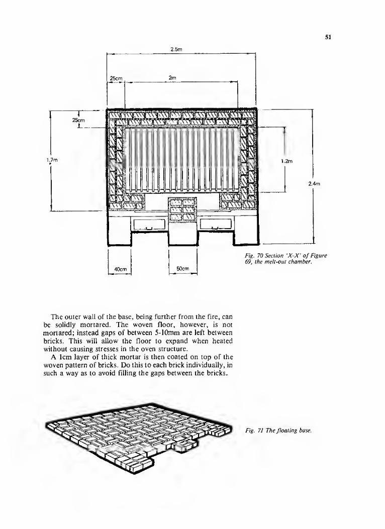
51
2.5m
The outer wall of the base, being further from the fire, can be solidly mortared. The woven floor, however, is not mortared; instead gaps of between 5- 10mm are left between bricks. This will allow the floor to expand when heated without causing stresses in the oven structure.
A 1cm layer of thick mortar is then coated on top of the woven pattern of bricks. Do this to each brick individually, in such a way as to avoid filling the gaps between the bricks.
Fig. 71 The floating base.

52
T\
Fig. 72 The initial build-up of the double walls and buttressed
pedestals.
A Fuel-feed door openings B Angled supports for ash-
and-draught doors. C Ash-and-draught door
openings.
Fig. 73 The build-up to the drip tray slides.
X Drip tray slides in location. Y Steel lintels over fuel-feed
doors. Z Steel lintels over ash-and-
draught doors.
The double walls of the oven are then built up to a height of about 60cm with mortar joints between each layer of bricks. A two to four centimetre insulation cavity is left between the double walls, and later filled with rubble. Openings are left in the walls for the ash-and-draught doors, and the fuel-feed doors, as shown in Figure 72.
Mild steel lintels are then laid across all four door-openings and the walls built up one more layer. Two mild steel drip- tray slides are then installed, supported at both ends and for half of their width by the oven walls (see Figure 73). A metal tray will later be slid into the oven, along these slides, to collect the waste wax at the beginning of the melt-out operation. It will then be withdrawn completely to allow a more direct heat to reach the moulds.

53
OVEN CONSTRUCTION MATERIALS — BASIC LIST
Materia! Qty/Length / Weigh t Use
1. Bricks 400-1000 Construction
2. Mild steel angle-iron (50mm x 50mm)
7 metres Oven-door retaining slide and grille frame.
3. Mild steel construction rod (12mm diameter)
As required Grille rods.
4. 600mm x 400mm mild steel plate (4mm thick)
2 Oven doors.
5. 400mm x 300mm mild steel plate (4mm thick)
2 Draught doors.
6. Mild steel flat-bar (3mm thick x 50mm wide)
5 metres Drip-tray slides.
7. Fabricated sheet-metal pipe (150mm dia. x required length)
1 Chimney pipe.
8. Mild steel sheet (2.25m by 1.3m x 4mm thick)
1 Drip-tray.
9. Miscellaneous metal As required Door-opening lintels, door handles, chimney supports, fuel-feed doors, draught door surrounds, etc.
10. Mortar mixture 200kgs approx. Construction mortar and oven lining and coating.
The oven walls are then built up one more layer, leaving an opening for the drip-tray on the left side, which is then spanned by another mild steel lintel. At this level also, two lengths of angle-iron are installed. These form the frame for the burn-out grille (see Figure 74). The grille rods are laid at the required spacing, fitting loosely into the angle-iron frame, with an allowance of 1cm on their length for expansion when heated. These rods will be retained in their positions by the mortar lining, which is applied to the inner surfaces of the
Fig. 74 The burn-out grille level.
A Steel lintel over drip tray slot.
B Angle-iron grille frame. C Grille rods.

54
oven doors slide.
oven as it is being constructed. The mortar for the lining should be mixed according to the appropriate recipe given in Chapter 7.
Next, the oven is built up to a height of approximately 1.6m. The oven door retaining slide is laid across the central column and the walls built up one more layer. Make sure to leave a gap of between 1-1.5cm between the front wall and the closest edge of the retaining slide (see Figure 75). This gap
Dimension 'y'
Fig. 76 Plan view of the oven, showing dimension into which
the arched roof will fit.

55
will be reduced to 5-7mm when the outer surface of the oven is later coated with mortar. The next layer of bricks is a single outer wall.
The roof and chimney
The next stage is to construct the arched roof and chimney. First a sheet of plywood, 3-5mm thick, should be cut to a width equal to dimension ‘X’ and at least 15cm longer than dimension ‘Y’ in Figure 76.
Next, test the plywood in location, making the centre of the arch about 15-20cm higher than the top of the single row of bricks, as in Figure 77. Cut away any surplus plywood. The hole for the chimney should then be cut in the centre of the plywood. The plywood and chimney are then set up as
A completed melt-out furnace, Ghana.
Fig. 77 Front elevation of the oven, showing plywood arch and chimney.
A Lintels over oven doors. B Chimney pipe. C Plywood arch in location.
The chimney pipe must be secured in position above the oven before proceeding, even if the method of securing it is purely temporary. Then plaster a 1cm layer over the plywood. The bricks are now laid in and wedged edge to edge, working from both sides to the centre. At the upper surfaces, where the bricks do not touch, wedge broken pieces of brick into the gaps. The aim is to keystone every brick, which will make the arch self-supporting when the plywood is burned out.
When the arch is complete, if the weight of the chimney is not to be completely taken by the building wall or roof through which it passes, it may be necessary to weld some mild steel feet to the chimney pipe where it touches the brick arch (see item ‘A’ in Figure 78). Also, the front and back walls beneath the arch must now be built up.
Once the chimney is secure, the outer surfaces of the oven are coated uniformly with mortar. Any areas of the inner surfaces which have not already been lined should now be finished off using the recommended mortar mixture given in Chapter 7. The doors can be fitted once the oven has dried out.

56
Fig. 78 Keystoned brick arch is built up from both sides
to the centre.
A Bricks built up from both sides.
B Chimney supported in position.
C Plywood coated with mortar.
Completing the oven
The oven should be allowed to dry out slowly. Because it consists of more wet material than the furnace, it is best to allow about one week for the drying operation. Again, drying may need to be hastened in humid climates by building a small wood fire in the oven grate on the fourth or fifth day of drying.
As in the case of the furnace, cracks will inevitably appear in the lining and outer coating during drying. This is normal, and all cracks should be filled with mortar and smoothed with a wet cloth. Cracks may also appear after the first few firings and should always be repaired as indicated above.
Fig. 79 Completion of oven.
A Mild steel feet welded to
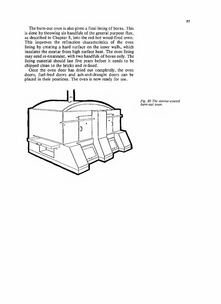
57
The burn-out oven is also given a final lining of borax. This is done by throwing six handfuls of the general purpose flux, as described in Chapter 8, into the red-hot wood-fired oven. This improves the refraction characteristics of the oven lining by creating a hard surface on the inner walls, which insulates the mortar from high surface heat. The oven lining may need re-treatment, with two handfuls of borax only. The lining material should last five years before it needs to be chipped clean to the bricks and re-lined.
Once the oven door has dried out completely, the oven doors, fuel-feed doors and ash-and-draught doors can be placed in their positions. The oven is now ready for use.

58
Fig. 81 A typical crucible.
Fig. 82 Home-made scissor tongs.
Fig. 83 Home-made pouring bar.
Chapter 10: Crucible-making and maintenance
If it is possible to buy a commercially manufactured crucible locally in which to melt casting alloys, then this is the best course of action. However, crucibles are not always available in developing countries, and prices may also be prohibitive. In such situations, crucibles of lower quality and shorter life¬ span may be home-made. Again, the only guide to success is experimentation.
Industrial crucibles are mostly made from clay and graphite. They are quite fragile when cold, and must be handled with care. When heated, however, they possess considerable strength. Newly manufactured crucibles contain a small amount of moisture, and should be dried out slowly and uniformly before use.
All crucibles become somewhat plastic when heated, and serious stresses and strains are set up in their structures if the tongs used to remove them from the furnace do not fit properly. The author usually makes his own scissor-tongs from mild steel bar, tube or 1" water pipe. This design may be slipped over the top of the crucible and closed around the circumference near the top. These tongs are ideal for getting the crucible out of the melt-chamber of the furnace. For the casting operation, however, the crucible should be transferred to a pouring bar.
Commercially manufactured crucibles are numbered from 1 to 400, according to their capacity. Each successive number indicates an increase of 31b in the bronze scrap-holding capacity of a crucible. For example, a No.5 crucible will hold 151b, or approximately 7kg of casting bronze.
Home-made crucibles
If you decide to make your own crucible, make sure that the materials you select are uniform and of the best available quality. Clay of a light colour is mixed with an equal volume of graphite. Dung-liquor is then added in the proportion of
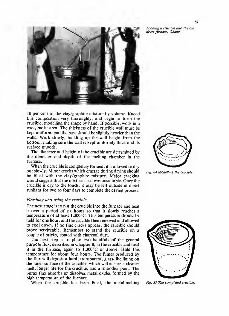
59
10 per cent of the clay/graphite mixture by volume. Knead this composition very thoroughly, and begin to form the crucible, modelling the shape by hand. If possible, work in a cool, moist area. The thickness of the crucible wall must be kept uniform, and the base should be slightly heavier than the walls. Work slowly, building up the wall height from the bottom, making sure the wall is kept uniformly thick and its surface smooth.
The diameter and height of the crucible are determined by the diameter and depth of the melting chamber in the furnace.
When the crucible is completely formed, it is allowed to dry out slowly. Minor cracks which emerge during drying should be filled with the clay/graphite mixture. Major cracking would suggest that the mixture used was unsuitable. Once the crucible is dry to the touch, it may be left outside in direct sunlight for two to four days to complete the drying process.
Finishing and using the crucible
The next stage is to put the crucible into the furnace and heat it over a period of six hours so that it slowly reaches a temperature of at least 1,300°C. This temperature should be held for one hour, and the crucible then removed and allowed to cool down. If no fine cracks appear, the crucible should prove serviceable. Remember to stand the crucible on a couple of bricks, coated with charcoal dust.
The next step is to place two handfuls of the general purpose flux, described in Chapter 8, in the crucible and heat it in the furnace, again to 1,300°C or above. Hold this temperature for about four hours. The fumes produced by the flux will deposit a hard, transparent, glass-like lining on the inner surface of the crucible, which will ensure a cleaner melt, longer life for the crucible, and a smoother pour. The borax flux absorbs or dissolves metal oxides formed by the high temperature of the furnace.
When the crucible has been lined, the metal-melting
Loading a crucible into the oil- drum furnace, Ghana
Fig. 84 Modelling the crucible.
Fig. 85 The completed crucible.

60
An improvised blower for the furnace. Upper Volta
operation can begin. With proper care, a commercial crucible could produce up to 100 melts before deteriorating. Naturally, a home-made crucible will have a much shorter life-span.
At the end of a day’s work, the crucible should be completely emptied of metal. If any metal is left in the bottom of the crucible, it will contract as it cools. When it is subsequently reheated it will expand and set up stresses in the crucible walls, which will crack. The best policy is to empty the crucible completely each time a pour is made. This may be done by always having a few simple ingot moulds available, into which surplus metal can be poured.

61
Chapter 11: Preparing non-ferrous metals for casting
In the author’s experience the alloys most commonly used in the lost-wax casting process are brass and bronze. Aluminium, because of its low melting point, would also be suitable for the casting process outlined in this manual. The melting points and boiling points of a number of metals are given in a table in this chapter.
Brass is essentially an alloy of copper and zinc. Brasses containing zinc in the proportion of 36 per cent or less are termed Alpha brasses, and have excellent cold-working qualities. Where 37 per cent or more zinc is present in the alloy, Beta brasses are produced, which have very good hot working characteristics. Leaded brasses, containing 0.5 to 3 per cent lead, are more suitable for machining.
Bronze is an alloy of copper and tin. Phosphor bronze alloys, in common use today, are variations on the basic alloy. The tin content of phosphor bronze alloys varies from 1.25 to 10 per cent. The most common phosphor bronze alloy contains 5 per cent tin and 0.35 per cent phosphorus. This alloy is widely used in the manufacture of simple bush- bearings.
There are also special alloys for casting, including cast- leaded tin bronzes, cast-leaded brasses, cast nickel silver, and cast aluminum bronzes.
TABLE OF MELTING AND BOILING POINTS IN DEGREES CENTIGRADE FOR SOME COMMON BASE METALS.
(SEE APPENDIX FOR COMPLETE LIST OF MELTING POINTS OF METALS.)
Melting Boiling Meta1 point (°C) point (°C)
Copper 1,083 2,595 Lead 327.35 1,740 Tin 231.9 2,270 Zinc 419.4 906 Aluminium 660 2,060 Nickel 1,458 2,730
Scrap sorting
The sorting and selection of non-ferrous scrap metal in developing countries is a hit-and-miss process. In almost all Third World art foundries in which the author has worked, the most questionable process has been scrap metal selection. Most casters accept what they get, and indeed are happy to

get it. They rarely consider whether the metal they melt may contain pieces of iron, tin, nickel, lead, zinc, aluminium, chrome or steel. The author once checked a 25kg load of scrap by passing a permanent magnet across the surface, after spreading the scrap on a table. This resulted in approximately 2.5kg of iron and steel filings being extracted from material which was assumed to be ready for casting. And even when ferrous metals have been eliminated, it is virtually impossible to refine the scrap to such a degree that it could be said to be definitely either bronze or brass, or any other alloy.
To some extent, bronze and brass can be identified by their colour, and separated. But without proper laboratory facilities, there is probably no way to perfect the selection of metal. When bronzes and brasses have previously been melted together, which is common in developing countries, the village casting-shop must simply accept the situation. Purer metals, direct from the refinery are only obtainable in more developed countries, where exact specifications are stated and satisfied. This situation, however, is a long way off in most areas where this manual is likely to be most useful. It can only be suggested that care be taken to clean the metal scrap of any obvious, known impurities, such as plated articles, ferrous metals and dubious-looking alloys.
Pre-melting scrap
One very positive method of producing a cleaner casting metal of uniform quality is to pre-melt the scrap and make it into ingots. Whenever melting any scrap, especially aluminium, never allow water, no matter how small the amount, to enter the crucible. An explosion can happen if you do. Load 25kg of sorted scrap into the crucible. Add approximately 50g of borax, 50g of boric acid, 30g of common salt, and a few pieces of charcoal. Place the crucible in the furnace and bring to melting point, when the surface of the molten metal will appear mirror-like. The additives suggested will help to clean out impurities, and will assist the dross in attracting those impurities into a single mass. As the temperature of the furnace rises above the melting point of the scrap metal, dirt and dross will come to the top surface. These impurities can then be removed, using a purpose- designed iron cup with a long handle. This cup should be heated prior to entry into the molten metal. Do not overheat the melt, as this will cause gases to enter into the metal, resulting in porous castings. Another problem of overheating is that the alloy will begin to break down, as the lesser metals form oxides and burn off.
When the dross has been removed from the surface of the molten metal, the purified alloy can be poured into ingot moulds, which can be made from a clay mould-mixture, or from angle-iron. The ingot moulds should be pre-heated and lightly oiled. Any heavy-bodied oil, such as filtered old engine-oil, will suffice. Oiling the moulds ensures that the ingots can be easily removed.

Quality of scrap
There is little more that can be done to improve casting metals under the circumstances prevailing in developing countries. As far as casting art objects is concerned, this is not a serious problem. Some of the finest castings seen by the
author have been produced by craftsmen who were unaware of the composition of the alloys they used. When one caster was asked how he achieved such a fine quality, he replied, ‘I take my scrap (unchecked) and melt it. When I see green smoke, I add twenty to thirty old flashlight batteries. I then wait for more green smoke, then white smoke. Then I cast.’ This is a really startling ability to read chemical reactions, which would send shivers down the spine of a trained metallurgist. This craftsman had been taught by his father, who was taught by his father, to wait for the white smoke! As long as he can produce works of art by this method, it is going to be difficult to convince him to wait for the red smoke!
Until the need arises for a more precise material, for example phosphor-bronze, for bush-bearing manufacture, it is not very important whether the material used is brass, bronze, or some other alloy, as long as the quality of the casting is sound and the colour of the metal is pleasing. Where progress is made in the introduction of industrial products, made from specified materials of standard composition, special arrangements for the supply of standard alloys would be a prime condition of success.

THIS PAGE IS BLANK but this is not a printing or scanning
fault and no content is missing.

APPENDICES

THIS PAGE IS BLANK but this is not a printing or scanning
fault and no content is missing.

67
Appendix 1:
Case studies
1. Upper Volta
The Derm6 Bronze Casting foundry and art works is an old established family business which has existed for many years. The foundry employs approximately 25 skilled workers engaged in the manufacture of traditional art, most of which is sold to the tourist market. The Derm6 foundry appears to be the largest manufacturer in Upper Volta and enjoys sales in Ghana, Ivory Coast, Togo and Niger, along with sales to European countries and the United States. The quality of castings sold is very high, and at first the output seemed to require little if any assistance. Upon further investigation, at the factory premises, it became evident that a great deal of work was needed. More than 50 per cent of the castings produced were rejects. All the problems a foundry encounters seem to have been present, and Mr Derme could not obtain simple information and solutions to his problems. The wax work was of a very high quality, only to be reduced to unrecognizable masses of burnt bronze. If a piece was salvageable, many days and hands were needed to restore the piece to a saleable item. This situation was creating severe problems in production, sales and prices.
The production of the castings was carried out in a romantic, old-world, traditional way, not unique to this part of the world. There had been slight improvements in the moulding procedure but for most parts of the process further improvements were greatly needed. Upon further investigations it was discovered the scrap metal collection of bronze/brass was not at all controlled or cleaned of any foreign matter, thus leading to defective metal melts. All collected metal (even plated steel) were dumped into a crucible and the process begun. Heat varied from very hot to
cold, to hot again — on occasions the melt stopped because not enough wood or charcoal had been prepared. The moulds were heated in much the same way: they were all piled up in a heap and a fire built around them, with the outside moulds receiving most of the heat very quickly, and the interior ones being gradually heated but without reaching a proper even temperature for a complete burn-out of wax.
First, I built the 45 gallon drum furnace for metal melt. This was a prerequisite for a uniform mixture of pre-cleaned, sorted metal. It appears to me that many of the problems were limited to the melting of the metal, the introduction of

gases and dirt, and lack of heat control. The next step was to prepare a flux to clean the melt and to assist in the pouring procedures. This step increased the quality of casting by approximately 20 per cent. Due to time limitations I was not able to build a proper burn-out oven, but provided simple instructions and details for the building of one. I can only assume that this would also increase the quality by 20 per cent. Certainly, less handling of the fragile moulds and less ‘knocking about’ can be expected, if a heat-controlled burn¬ out is built.
I discussed simply with Mr Derme what happens to metal and wax when heated, and although his family has been in the business for years it was all new to him. He had followed the path of his forefathers, not questioning the lack of efficiency nor knowing how to achieve a better quality. He had realized that with simple improved methods, a better way must be found — it was with much pleasure and honour that I was able to bring him a little closer to his goal.
2. Papua New Guinea
It might be thought that all countries have had some history of foundry casting somewhere in their past. But Papua New Guinea is a unique example where no evidence of casting or foundry practices has been found. No indigenous artifacts, weapons or items have ever been found, that gives the slightest hint of the coming of the ‘bronze age’. It was therefore greatly encouraging and with much satisfaction that a foundry was started, operated and was able to support higher living standards for a group of families who previously had no understanding, experience or encouragement to proceed with such a venture.
One can imagine that, without a basic foundry industry already in operation in a country, the problems of locating even the simplest of equipment become almost unsurmountable. Approximately 50 per cent of the time spent assisting Hanuatek (the manufacturing and production arm of South Pacific Appropriate Technology Foundation) was in obtaining the ingredients that go to make up a basic foundry — bricks were begged, borrowed and stolen, and clay was brought in sacks, barrels and plastic bags. But what really mattered was that we were able to build a business that, directly and indirectly, now supports many families that previously had no means of making a living. The training of people who had no idea about foundry, casting, forming of metals, quality control, export, utilization of scrap metals (for a very handsome profit), organization and management of their own ‘home-built’, locally produced, foundry was indeed a very successful undertaking.
The Hanuatek foundry, a simple uncomplicated operation, proved that with co-operation and will, a viable industry can be established in a short period of time and at minimal cost. Certain aid organizations spent years looking into the potential for foundry operation in Papua New Guinea. These

69
investigations entailed great cost, much report-writing and investigation — but with no results. Naturally the scale envisaged by the experts looking into the potential of a foundry industry comes nowhere near the Hanuatak foundry. But the first indigenous casting foundry now exists, built at a very low cost and operated by the people themselves. The product produced at present is ingots of scrap aluminium, which are exported to Australia — where it was recently remarked how pleased they were with the high quality and standard. The Australians have no idea that their ingots are produced in a ‘cow-dung’ furnace.
The author at work in Papua New Guinea: mixing day, cow-dung and sand.

70
Appendix 2: Review and check list
Once all equipment has been made and the necessary materials located it is time to begin the process. Before starting, however, it is important to review the process many times with the people involved. A step-by-step check list is extremely important and should be used throughout the operation.
Safety checks Are all gas/oil joints and connections leak-free? Are all gas containers, storage tanks etc behind the safety walls? Are all electrical connections and cables insulated, grounded and placed
out of the way of activities? Is the area well ventilated and properly illuminated? Is the area free from obstructions, debris and ground dirt? Are the operators wearing the correct and sufficient protective shoes,
clothing, face masks and gloves? Has the working area and its surroundings been cleared of visitors,
children and anyone not involved in the actual casting? Are first-aid supplies adequate? Have you had a few ‘dry-run’ test first runs to familiarize the
operators with the casting techniques? Have provisions been made for cold water supply/tank in case of an
accident such as bums? Is all metal to be cast dry? Have you double-checked all safely procedures?
Wax work
Assuming the original model (the master piece) has been prepared and finished to perfection (as required by the final casting quality), wax is then introduced into a mould (plaster, stone, wood, silicone, etc), by either gravity pouring or under pressure. The temperature of the wax should be maintained exactly at that necessary to produce a facsimile of the mould surface. Temperature variance will render faulty wax patterns. The wax pattern is cooled, removed from the mould and made ready (by a detergent/alcohol dip — reducing the surface tension).
Clay /dung refractory mould coating The wax pattern is carefully covered with the clay/dung coating and left to dry out. Don’t rush this step because the mould will crack severely if the necessary length of time and temperature are not strictly followed. Minor surface cracks can be repaired when the mould is dry.
Burn-out Once the moulds are considered to be dry, carefully invert the mould so that the sprue is facing downwards. The final wax removal is carried out in the bum-out oven but steaming or low heat (about 150°-200°C) can be used to remove the majority of the wax from the interior of the mould. Carefuly place the partially empty mould in the cold burn-out oven, slowly bringing the heat of the oven up to 800°C, over an 8-hour period. Hold the

800°C temperature for one hour, thus assuring the carbon has completely left the interior surface of the mould. The temperature of the mould will have to be reduced, by an amount depending on the metal to be cast.
Metal melt
Prior to melting, all metal should be prepared, cleaned and made into ingots. Metal temperature should be reached as quickly as possible and should not soak. (Soaking, when the metal is left in a hot furnace for too long a period of time, introduces gases into the melt and could burn off alloys.) Make sure to flux the metal just prior to casting, and clean dross.
Casting
Make sure moulds are securely placed in an upright position in a sand base. All tools required for casting should be checked beforehand, making sure they function properly and are placed where needed. When pouring make sure to pour into the mould in a steady stream approximately 2cm wide at crucible spout. Pour down alongside the sprue cup, allowing space for gases to escape from the interior of the mould. Once poured into the mould do no disturb the mould until the red glow (from the metal at the sprue cup) is no longer visible. Carefully sprinkle water on to the mould surface to cool down the casting. Wait 30 minutes, then proceed to remove the mould covering. Finish as required.

72
Appendix 3:
Glossary of casting terms
Alloy A metal produced by combining two or more metals, or a metal and a non-metallic element.
Braze To braze is to join with an oxy-acetalyine combination/burner two pieces of similar or dissimilar metal, such as brass or silver.
Burn-out The process of melting the wax out of the refractory-clay casting mould. Also, the term for heating and removing excess moisture from the mould in preparation for metal-pouring.
Burn-out oven A specially constructed kiln, the size and shape of which depends on the number and size of the moulds which will be routinely burned-out.
Chasing Creating designs and shapes in a softer metal by the use of a hammer and a polished steel tool.
Cold shunt A line which occurs on the surface of a casting because two streams of molten metal fail to unite owing to a temperature difference during pouring.
Core A mass of treated sand, plaster, clay, or other combined materials, used to fill a cavity in a mould when making a hollow casting.
Crucible A receptacle designed to hold metal to be melted and poured into moulds. Often made of graphite and clay, cast-iron, or other refractory materials.
Fillet weld A method of joining metal plates which are not in the same plane, by welding on the inside angle.
Fin Thin ridges of metal that can appear on the surface of castings if fine cracks have developed in the mould during burn-out or casting.
Flux A chemical substance, in liquid, paste or powder form, which improves the viscosity of metal by dissolving or preventing the formation of oxides and other foreign materials which might impede the flow of molten metal during pouring. Among the materials used in fluxes are borax, saltpetre, sal ammoniac, ordinary salt, boric acid, bottle glass and sulphur.
Ingot An oblong mass of cast metal. Ingots are usually processed further by rolling, forging, recasting or other methods of forming. Scrap metal which is melted into an ingot, and then re-melted and cast again into a finished produce, has the advantage of producing a more uniform and cleaner material, especially when treated with suitable fluxes during melting.
Investment The name given to both the process and the material used to encase a wax model to form a mould. The completed investment is heated

to remove the wax, thus leaving a hollow mould. The investment material described in this manual is based on a mixture of cow dung and clay. Other compounds and chemicals are used industrially, for example cristobalite (a form of silica) and gypsum plaster-slurry.
Masterpiece The original or first piece which can then act as a model, or pattern.
Melt furnace A heat chamber capable of reaching temperatures higher than 1,300°C in order to melt non-ferrous casting metals. Usually equipped with an electric forced-air blower.
Metal casting The process of pouring molten metal into a mould to produce a metal object of predetermined form. Also, the name given to the resulting object.
Model A descriptive term usually applied to an object to be copied in the process of casting.
Mould 1. A hollow form made of plaster, rubber, stone, wood etc, into which molten wax is cast/poured and left to cool and harden into the required shape.
2. A refractory object with a specially formed cavity in which molten metal can be held in a predetermined form until it solidifies. In the lost-wax casting system outlined in this manual, the mould cavity is achieved by building up a layer of clay mixed with cow dung on a wax pattern. When the wax has been melted out, the mould contains a hollow, negative, impression of the pattern.
Pattern A functional term for a wax model which is encased in a refractory clay mould, then melted out, leaving its impression in the clay mould.
Pouring cup The conical opening or depression in the top of a mould, into which the molten metal is first poured. It is located at the top of the sprue.
Porosity A defective condition of cast metals, characterized by blow holes and cavities in the finished object. This condition is often caused by shrinkage or trapped gases, which can result from improper venting of moulds, or overheating of the casting metal.
Refractory material Heat-resistant material, for example the clay mixtures used to line the furnace and oven, and to form the casting moulds.
Risers Channels in the mould body, designed to permit the escape of gases and air during the pouring operation, or as reservoirs to feed heavier sections of the casting during solidification. Rarely used in clay-body moulds.
Runners Supplementary narrow channels through which molten metal can pass to problem areas of the casting. The runners, where used, together with the sprue and pouring cup, form the gating system.
Scrap Metal which is unsuitable for direct use, but which can be reclaimed by melting and refining.
Sprue A vertical channel through a mould, connecting the pouring cup to the mould cavity. (The size of the sprue is determined by the pattern size and detail. If it is possible, in small-scale work, it is desirable that the main sprue should be as large (in a cross section) as the bulkiest part of the casting.)
Undercuts Recesses in wax patterns which cause problems when two-part moulds are being used. Undercuts reproduce projections on the mould, and these projections are shattered when attempts are made to open the mould. They should be avoided when using plaster moulds. If they are

unavoidable, the problem may be solved by the use of multi-part moulds, flexible rubber moulds Oatex, silicone, RTV, etc), or by reverting to the basic system of lost-wax casting.
Vents Narrow openings which are used to allow gases formed during casting to escape from the mould. Vents are rarely used with clay-body moulds, because these moulds can ‘breathe’.
Virgin metal Metal which has been smelted from ore and not previously used.
Appendix 4: Bibliography Cennino d’Andrea Cennini, The Craftsman’s Handbook (II Libro
Dell’Arte), (translated by Daniel V. Thompson, Jr), Dover Publications Inc., NYC. 1933.
Kasem Balajiva, Precision Casting in Brass and Bronze, ASRCT, Bangkok. 1968.
Murray Bovin, Centrifugal or Lost-wax Casting, Bovin Publishing NYC. 1971.
William B. Dick, Dick’s Encyclopedia of Practical Receipts and Processes, Funk and Wagnalls NY. 1870.
Dow Corning Corporation, Silicone, RTV and Silastic Technical Bulletins. 1963-80.
J.D. Harper, Small-scale Foundries for Developing Countries, Intermediate Technology Publications. 1981.
Investment Casting Handbook, Investment Casting Institute, Chicago. 1968.
Thelma R. Newman, Contemporary South-east Asia Arts and Crafts, Crown Publishers Inc., NYC. 1977.
Christian Schwahn, Workshop Methods for Gold and Silversmiths, Heywood and Company Ltd. 1960.
Appendix 5: Useful data Melting points of metals
Meta! °C Metal °C
Tin 231.9 Silver 960,5 Bismuth . 271.3 Gold 1,063.0 Cadmium 320.0 Copper 1,083.0 Lead 327.35 Manganese 1,260.0 Zinc 419.4 Nickel 1,458.0 Antimony 630.5 Cobalt 1,480.0 Magnesium 651.0 Iron 1,539.0 Aluminium 660.0
Relative characteristics of common metals (arranged in descending order for each property)
Malleability Ductility Tensile
strength
Gold Gold Nickel Silver Silver Iron
Aluminium Platinum Copper Copper Iron Platinum
Tin Copper Silver Platinum Aluminium Zinc
Lead Nickel Gold Zinc Zinc Aluminium Iron Tin Tin
Nickel Lead Lead