Embed Size (px)
Citation preview

Loudspeaker User’s Manual
Introduction ......................................................................................... 2Rigging Safely ..................................................................................... 2 Unpacking and checking for shipping damage ................................... 2 Selecting a Power Amplifier ................................................................ 2 Connecting to an Amplifier .................................................................. 2-3 Operating Tips ..................................................................................... 3 Switching to Bi-Amplified Operation .................................................... 3-4 Thermal Limiter Calibration ........................................................................ 4-5 Using the UMH Attachment Points ..................................................... 5 U-Bracket and Loudspeaker Mounting Hardware ............................... 5 Complex Conic Horn Orientation ........................................................ 5Loudspeakers with Transformers Installed ......................................... 5 Troubleshooting Tips ........................................................................... 5-6 Evaluating Failed Externally Powered Loudspeakers ......................... 7 Evaluating Failed Self-Powered Loudspeakers .................................. 7 Renkus-Heinz Painting Guidelines ..................................................... 7-8 Additional Information ................................................................................ 8
Table of Contents
Loudspeaker User’s Manual
Loudspeaker User’s Manual
Page 2
Page 2
INTRODUCTION
Congratulations on your purchase of a Renkus-Heinz loudspeaker. This manual will help you install and use your Renkus-Heinz loud-speaker properly so that it delivers years of trouble-free operation and superior performance, as it was designed to. RIGGING SAFELY
Before hanging or flying any Renkus-Heinz loudspeaker you should be familiar with the cabinet load ratings listed in this manual (see pg. 5) along with the rigging techniques and any special safety considerations appropriate for your intended use. Use only the UMH points on the loudspeaker cabinet intended for suspending the loudspeaker. You must determine the load requirements, dynamic loading and any other contributing factors affecting the suspended loudspeakers and any necessary safety factor for specific applications. You must also calcu-late the required load rating of the connection to any structure. Renkus-Heinz recommends that all rigging be done by qualified personnel in accordance with and in compliance with all federal, state and local regulations.
NOTICE: As the installer, you assume all liability for proper design, installation and use of any rigging systems. Renkus-Heinz strongly rec-ommends the following rigging system practices:
1. Thoroughly document your rigging with detailed drawings and parts lists. 2. Have a licensed structural engineer, architect or other qualified professional review and approve the rigging design and any building
attachments before you hang the loudspeakers. 3. It is always best to have a qualified professional rigger install and inspect the rigging system.
WARNING! Hanging loudspeakers is a serious undertaking that should be done only by qualified and experienced personnel.Renkus-Heinz is not responsible for any non-Renkus-Heinz products or for any misuse of Renkus-Heinz products.
UNPACKING & CHECKING FOR SHIPPING DAMAGE
Your Renkus-Heinz loudspeaker was completely tested and inspected before leaving the factory. Carefully inspect the shipping carton be-fore opening it, and then immediately inspect your new loudspeaker. If you find any damage notify the shipping company andRenkus-Heinz immediately. Only the consignee may institute a claim for damages incurred in shipping. Be sure to save the shipping carton and all packing materials.
SELECTING A POWER AMPLIFIER
Renkus-Heinz loudspeakers have three power specifications: RMS, Program and Peak. The Program rating is printed on the model number sticker on the back of the loudspeaker. The AES power rating is the long-term thermal power rating and is measured per AES2-2012. The Program power rating is 3 dB greater than the AES rating and is the recommended amplifier power rating for most systems. The Peak power rating is 12 dB greater than the AES long-term rating, this is per the AES2-2012 standard and is because the pink noise used as a test signal has a 12 dB peak-RMS ratio.
When selecting a power amplifier for your loudspeaker you should consider the needs of your specific application. For most applications, an amplifier equal to the Program power rating offers a good compromise between having enough power while at the same time not having so much power that it’s easy to blow up the loudspeakers. You will still want to have a long attack time, slow release time thermal limiter in the system as a precaution.
See page 4 for procedure and recommended voltages for setting thermal limiters.
If you need the maximum output capability of your loudspeaker, you should choose an amplifier whose RMS output rating is 2-3 times the program rating. This means the amplifier’s long-term thermal output greatly exceeds the capacity of the loudspeaker. You MUST have both long-term thermal limiters and short term peak limiters in the system to avoid loudspeaker damage. If your DSP has the option for look-ahead peak limiting, you should use it.
You can find more information in the Downloads section of our website, on setting limiters in our RH-DSP document, which lists the rec-ommended DSP paramaters for all of our current loudspeakers.
CONNECTING TO AN AMPLIFIER
Renkus-Heinz loudspeakers are available with four types of connectors; four- or eight-pole Neutrik SpeakOn connectors, terminal barrier strip, or rubber-jacketed wire pig-tail. The model/serial number label lists the connections for proper hook-up. We use the same numbering conventions for SpeakOn and terminal strip connectors: See Table 1 for proper wiring instructions. Pig-tail connections are color coded: the color code is shown on the model number plate. Always use crimp-on terminals with the terminal strip connections - do not connect bare wire.
Loudspeaker User’s Manual
Loudspeaker User’s Manual
Page 3
Page 3
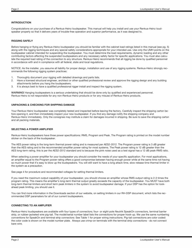
It’s possible that your speaker was specially ordered with a different type of connector, be sure to check the model number plate on your loudspeaker and follow the wiring diagram and instructions it displays.
Loudspeaker TypeTerminal or SpeakOn Connection
Fully Passive
1+, 1-Full Range
Low
Low
Low
Woofer 1
Mid **
Not Used
High
Mid/High
Low * Mid High
High ***Mid/High ***
Mid ***
Woofer 2 *
Mid/High
High **
2+, 2- 3+, 3- 4+, 4-
Bi-Amp, Two-way
Bi-Amp, Three-way
Tri-Amp, Three-way
Subwoofer
Passive Mid/High
Active Mid/High
Table 1
Notes:Standard connections shown. Check model plate for your specific connection! * When woofers wired separately ** Terminal strip or SpeakOn NL4 connection *** SpeakerOn NL8 connection (Touring products)
OPERATING TIPS
• Don’t drive any of your electronic equipment into clipping, particularly the power amplifiers. This can damage your loudspeaker. • If driven into clipping, even the amplifier with a power output rating lower than Renkus-Heinz’s power rating can cause damage to a
loudspeaker. • Avoid sustained microphone feedback. This may cause failure of mid and high frequency drivers. • Avoid extreme boosts on equalizers as these can cause excessive input to the drivers at the boosted frequencies. Cutting frequencies
is preferred to correct for frequency response problems. These problems include attenuating feedback frequencies or reducing exces-sive energy at certain frequencies due to room acoustics.
• Your loudspeaker should sound very good. However, even the finest loudspeaker won’t sound good in a room with poor acoustics. There is little you can do to overcome room acoustic problems with electronic adjustments. Carefully placing and aiming of the loud-speaker so that most of the sound is directed only at the audience is helpful in difficult rooms.
• Renkus-Heinz loudspeakers are capable of sound levels that can damage human hearing. Take precautions so that audiences are not exposed to such levels. If you must expose yourself to these kinds of volume levels, wear hearing protection.
• Be careful when moving or lifting the loudspeaker. Careless handling could result in injury to you or damage to the loudspeaker.
SWITCHING TO BI-AMPLIFIED OPERATION
Some Renkus-Heinz loudspeaker models can be switched from fully passive operation using the inter-nal crossover to bi-amplified operation using an external controller/crossover/DSP unit. These models can be identified by a round indicator window below the model name on the input connector panel. (Outlined in red at right.) If you choose to use your loudspeaker in the bi-amplified mode, be sure to obtain the DSP settings for your model from Renkus-Heinz and be sure to follow the section on setting limiters in this manual (see pg. 4). Your loudspeaker will have shipped wired for fully passive use, to convert to bi-amplified usage, follow these steps.
1. Remove the screws holding the input panel to the loudspeaker cabinet and then carefully remove the panel from the cabinet. A loudspeaker cable plugged into one of the inputs makes a handy “handle” for this procedure. See Figure 1.
Loudspeaker User’s Manual
Loudspeaker User’s Manual
Page 4
Page 4
THERMAL LIMITER CALIBRATION
You should always set limiters in the DSP processor you are using with your Renkus-Heinz loudspeakers, in order to protect them from damage. Here’s how to emulate the process Renkus-Heinz Engineering uses to set up limiters in the self-powered models. The following procedure is as close as you can get without access to the specialized equipment we use at the factory.
You will need a sine wave generator (or a test CD with sine waves of various frequencies) and a volt meter.
1) Set up your system’s gain structure.
2) Disconnect the loudspeakers from the amplifier. Do not set the limiters with the loudspeakers connected - you will damage the loudspeakers. This damage is not covered by our warranty!
3) Feed a sine wave signal into the amplifier. Use a frequency in the lower part of the driver’ s pass band: 60 Hz for subwoofers, 200 Hz for lows and fully passive speakers, 1 kHz for mid-ranges or mid-highs and 2.5 kHz for compression drivers.
4) Connect the volt meter to the amplifier outputs.
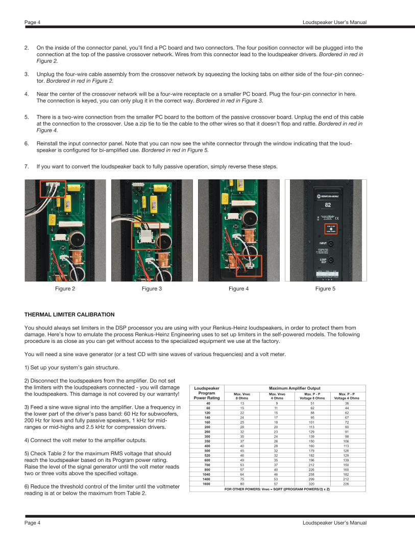
5) Check Table 2 for the maximum RMS voltage that should reach the loudspeaker based on its Program power rating. Raise the level of the signal generator until the volt meter reads two or three volts above the specified voltage.
6) Reduce the threshold control of the limiter until the voltmeter reading is at or below the maximum from Table 2.
LoudspeakerProgram
Power Rating
Maximum Amplifier Output
FOR OTHER POWERS: VRMS = SQRT ((PROGRAM POWERS/2) x Z)
Max. VRMS8 Ohms
40 13 9 51 3660 15 11 62 44
120 22 15 88 62140 24 17 95 67160 25 18 101 72200 28 20 113 80260 32 23 129 91300 35 24 139 98350 37 26 150 106400 40 28 160 113500 45 32 179 126520 46 32 182 129600 49 35 196 139700 53 37 212 150800 57 40 226 160
1040 64 46 258 1821400 75 53 299 2121600 80 57 320 226
Max. VRMS4 Ohms
Max. P - PVoltage 8 Ohms
Max. P - PVoltage 4 Ohms
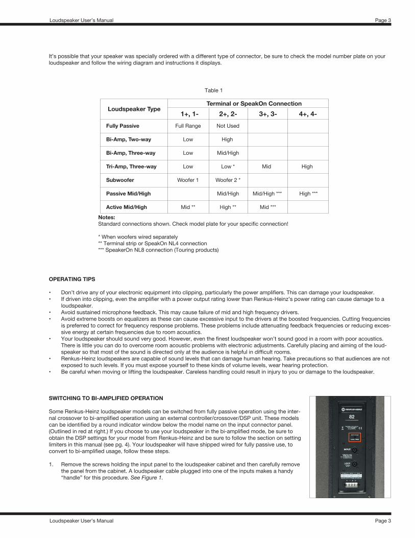
Figure 2 Figure 3 Figure 4 Figure 5
2. On the inside of the connector panel, you’ll find a PC board and two connectors. The four position connector will be plugged into the connection at the top of the passive crossover network. Wires from this connector lead to the loudspeaker drivers. Bordered in red in Figure 2.
3. Unplug the four-wire cable assembly from the crossover network by squeezing the locking tabs on either side of the four-pin connec-tor. Bordered in red in Figure 2.
4. Near the center of the crossover network will be a four-wire receptacle on a smaller PC board. Plug the four-pin connector in here. The connection is keyed, you can only plug it in the correct way. Bordered in red in Figure 3.
5. There is a two-wire connection from the smaller PC board to the bottom of the passive crossover board. Unplug the end of this cable at the connection to the crossover. Use a zip tie to tie the cable to the other wires so that it doesn’t flop and rattle. Bordered in red in Figure 4.
6. Reinstall the input connector panel. Note that you can now see the white connector through the window indicating that the loud-speaker is configured for bi-amplified use. Bordered in red in Figure 5.
7. If you want to convert the loudspeaker back to fully passive operation, simply reverse these steps.
Loudspeaker User’s Manual
Loudspeaker User’s Manual
Page 5
Page 5
Following the procedure on previous page will provide some protection against overpowering and damaging your loudspeakers. It is important to note that if your amplifier is capable of peak-to-peak voltages in excess of those in the table, you also need to provide fast acting peak limiters for your system. Renkus-Heinz amplifiers have all these functions incorporated into their design and only self-powered units with Loudspeaker Specific Processing calibrated at the Renkus-Heinz factory satisfies the terms of our warranty. If you use third party processing that is calibrated in the field, you will not be able to obtain warranty replacements for blown speaker components. If you do not need the full output of the loudspeaker for your application you can save money by using a smaller amplifier.
USING THE UNIVERSAL MOUNTING HARDWARE ATTACHMENT POINTS
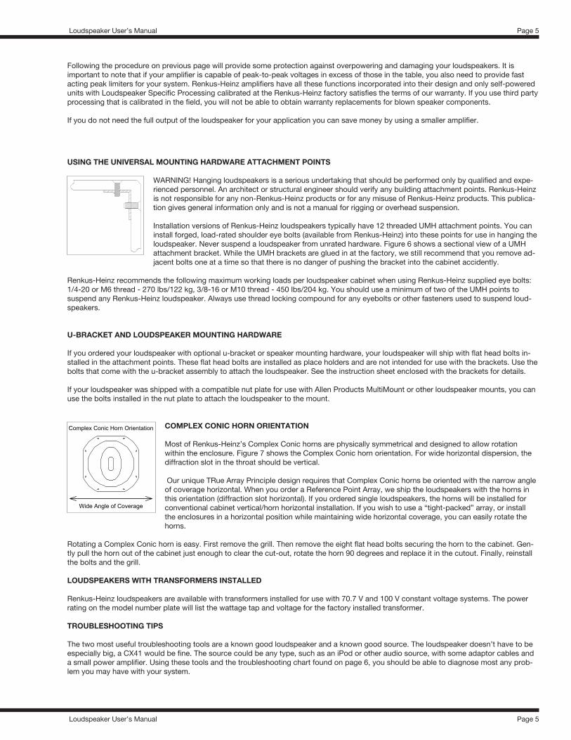
WARNING! Hanging loudspeakers is a serious undertaking that should be performed only by qualified and expe-rienced personnel. An architect or structural engineer should verify any building attachment points. Renkus-Heinz is not responsible for any non-Renkus-Heinz products or for any misuse of Renkus-Heinz products. This publica-tion gives general information only and is not a manual for rigging or overhead suspension. Installation versions of Renkus-Heinz loudspeakers typically have 12 threaded UMH attachment points. You can install forged, load-rated shoulder eye bolts (available from Renkus-Heinz) into these points for use in hanging the loudspeaker. Never suspend a loudspeaker from unrated hardware. Figure 6 shows a sectional view of a UMH attachment bracket. While the UMH brackets are glued in at the factory, we still recommend that you remove ad-jacent bolts one at a time so that there is no danger of pushing the bracket into the cabinet accidently.
Renkus-Heinz recommends the following maximum working loads per loudspeaker cabinet when using Renkus-Heinz supplied eye bolts: 1/4-20 or M6 thread - 270 lbs/122 kg, 3/8-16 or M10 thread - 450 lbs/204 kg. You should use a minimum of two of the UMH points to suspend any Renkus-Heinz loudspeaker. Always use thread locking compound for any eyebolts or other fasteners used to suspend loud-speakers.
U-BRACKET AND LOUDSPEAKER MOUNTING HARDWARE
If you ordered your loudspeaker with optional u-bracket or speaker mounting hardware, your loudspeaker will ship with flat head bolts in-stalled in the attachment points. These flat head bolts are installed as place holders and are not intended for use with the brackets. Use the bolts that come with the u-bracket assembly to attach the loudspeaker. See the instruction sheet enclosed with the brackets for details.
If your loudspeaker was shipped with a compatible nut plate for use with Allen Products MultiMount or other loudspeaker mounts, you can use the bolts installed in the nut plate to attach the loudspeaker to the mount.
COMPLEX CONIC HORN ORIENTATION
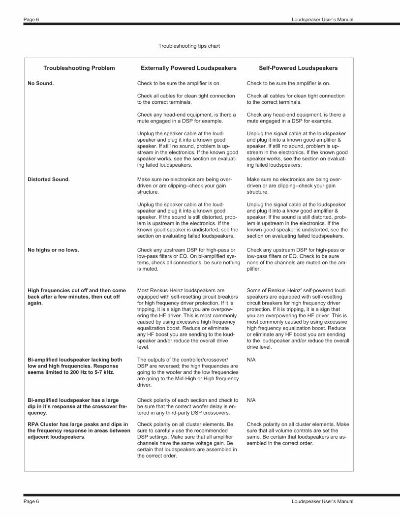
Most of Renkus-Heinz’s Complex Conic horns are physically symmetrical and designed to allow rotation within the enclosure. Figure 7 shows the Complex Conic horn orientation. For wide horizontal dispersion, the diffraction slot in the throat should be vertical.
Our unique TRue Array Principle design requires that Complex Conic horns be oriented with the narrow angle of coverage horizontal. When you order a Reference Point Array, we ship the loudspeakers with the horns in this orientation (diffraction slot horizontal). If you ordered single loudspeakers, the horns will be installed for conventional cabinet vertical/horn horizontal installation. If you wish to use a “tight-packed” array, or install the enclosures in a horizontal position while maintaining wide horizontal coverage, you can easily rotate the horns.
Rotating a Complex Conic horn is easy. First remove the grill. Then remove the eight flat head bolts securing the horn to the cabinet. Gen-tly pull the horn out of the cabinet just enough to clear the cut-out, rotate the horn 90 degrees and replace it in the cutout. Finally, reinstall the bolts and the grill.
LOUDSPEAKERS WITH TRANSFORMERS INSTALLED
Renkus-Heinz loudspeakers are available with transformers installed for use with 70.7 V and 100 V constant voltage systems. The power rating on the model number plate will list the wattage tap and voltage for the factory installed transformer. TROUBLESHOOTING TIPS
The two most useful troubleshooting tools are a known good loudspeaker and a known good source. The loudspeaker doesn’t have to be especially big, a CX41 would be fine. The source could be any type, such as an iPod or other audio source, with some adaptor cables and a small power amplifier. Using these tools and the troubleshooting chart found on page 6, you should be able to diagnose most any prob-lem you may have with your system.
Loudspeaker User’s Manual
Loudspeaker User’s Manual
Page 6
Page 6
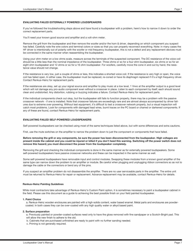
Troubleshooting Problem Externally Powered Loudspeakers Self-Powered Loudspeakers
No Sound. Check to be sure the amplifier is on. Check all cables for clean tight connection to the correct terminals. Check any head-end equipment, is there a mute engaged in a DSP for example. Unplug the speaker cable at the loud-speaker and plug it into a known good speaker. If still no sound, problem is up-stream in the electronics. If the known good speaker works, see the section on evaluat-ing failed loudspeakers.
Check to be sure the amplifier is on. Check all cables for clean tight connection to the correct terminals. Check any head-end equipment, is there a mute engaged in a DSP for example. Unplug the signal cable at the loudspeaker and plug it into a known good amplifier & speaker. If still no sound, problem is up-stream in the electronics. If the known good speaker works, see the section on evaluat-ing failed loudspeakers.
Distorted Sound. Make sure no electronics are being over-driven or are clipping--check your gain structure. Unplug the speaker cable at the loud-speaker and plug it into a known good speaker. If the sound is still distorted, prob-lem is upstream in the electronics. If the known good speaker is undistorted, see the section on evaluating failed loudspeakers.
Make sure no electronics are being over-driven or are clipping--check your gain structure. Unplug the signal cable at the loudspeaker and plug it into a know good amplifier & speaker. If the sound is still distorted, prob-lem is upstream in the electronics. If the known good speaker is undistorted, see the section on evaluating failed loudspeakers.
No highs or no lows. Check any upstream DSP for high-pass or low-pass filters or EQ. On bi-amplified sys-tems, check all connections, be sure nothing is muted.
Check any upstream DSP for high-pass or low-pass filters or EQ. Check to be sure none of the channels are muted on the am-plifier.
High frequencies cut off and then come back after a few minutes, then cut off again.
Most Renkus-Heinz loudspeakers are equipped with self-resetting circuit breakers for high frequency driver protection. If it is tripping, it is a sign that you are overpow-ering the HF driver. This is most commonly caused by using excessive high frequency equalization boost. Reduce or eliminate any HF boost you are sending to the loud-speaker and/or reduce the overall drive level.
Some of Renkus-Heinz’ self-powered loud-speakers are equipped with self-resetting circuit breakers for high frequency driver protection. If it is tripping, it is a sign that you are overpowering the HF driver. This is most commonly caused by using excessive high frequency equalization boost. Reduce or eliminate any HF boost you are sending to the loudspeaker and/or reduce the overall drive level.
Bi-amplified loudspeaker lacking both low and high frequencies. Response seems limited to 200 Hz to 5-7 kHz.
The outputs of the controller/crossover/DSP are reversed; the high frequencies are going to the woofer and the low frequencies are going to the Mid-High or High frequency driver.
N/A
Bi-amplified loudspeaker has a large dip in it’s response at the crossover fre-quency.
Check polarity of each section and check to be sure that the correct woofer delay is en-tered in any third-party DSP crossovers.
N/A
RPA Cluster has large peaks and dips in the frequency response in areas between adjacent loudspeakers.
Check polarity on all cluster elements. Be sure to carefully use the recommended DSP settings. Make sure that all amplifier channels have the same voltage gain. Be certain that loudspeakers are assembled in the correct order.
Check polarity on all cluster elements. Make sure that all volume controls are set the same. Be certain that loudspeakers are as-sembled in the correct order.
Troubleshooting tips chart
Loudspeaker User’s Manual
Loudspeaker User’s Manual
Page 7
Page 7
EVALUATING FAILED EXTERNALLY POWERED LOUDSPEAKERS
If you’ve followed the troubleshooting steps above and have found a loudspeaker with a problem, here’s how to narrow it down to order the correct replacement parts.
You’ll need your known good source and amplifier and a volt-ohm meter.
Remove the grill from the loudspeaker and then remove the woofer and/or the horn & driver, depending on which component you suspect has failed. Carefully note the wire colors and terminal colors or sizes so that you can properly reconnect everything. Note: in many cases the HF driver is intentionally out of polarity with the woofer or mid frequency loudspeaker, this is not a defect and any replacement devices must be connected in the same manner when reassembling the loudspeaker.
Using your ohm meter on a low ohms scale, measure across the terminals of the suspected component. The DC resistance of the voice coil should be a little less than the nominal impedance of the loudspeaker. Three ohms or so for a four ohm loudspeaker, six ohms or so for an eight ohm loudspeaker and 12 ohms or so for a 16 ohm loudspeaker. For woofers, carefully move the cone in and out by hand, the resis-tance value should not change.
If the resistance is very low, just a couple of ohms or less, this indicates a shorted voice coil. If the resistance is very high or open, the voice coil has failed open. In either case, the loudspeaker must be replaced, re-coned or have its diaphragm replaced if it’s a high frequency driver. Contact Renkus-Heinz for replacement parts.
If the resistances are okay, set up your signal source and amplifier to play music at a low level, 1 VRMS at the amplifier output is a good level which will not damage any pro-audio component even without a crossover in place. Listen to each component by itself; each should sound clean and undistorted. Any distortion, rubbing or buzzing indicates a failure. Contact Renkus-Heinz for replacement parts.
If the individual components check out okay, but the loudspeaker still fails to function properly, there may be a problem with the passive crossover network - if one is installed. Note that crossover failures are exceedingly rare and are almost always accompanied by driver fail-ures due to extreme over-powering. Without test equipment, it’s difficult to test a crossover network properly, but a visual inspection will catch most problems. Look for components with damaged lead wires, burnt traces on the PC board or charred or darkened components. If any of these are found, contact Renkus-Heinz for replacement parts.
EVALUATING FAILED SELF-POWERED LOUDSPEAKERS
Self-powered loudspeakers can be checked using most of the same techniques listed above, but with some differences and extra cautions.
First, use the mute switches on the amplifier to narrow the problem down to just the component or components that have failed.
Before removing the grill or any components, be sure the power has been disconnected from the loudspeaker. High voltages are present inside the cabinet and you could be injured or killed if you don’t heed this warning. Switching off the power switch does not remove this hazard; you must disconnect the power from the loudspeaker completely.
Removing the grill and checking the individual components is done in the same manner as for externally powered loudspeakers. Some self-powered loudspeakers have passive crossover networks and these can be inspected in the same manner as well.
Some self-powered loudspeakers have removable input and control modules. Swapping these modules from a known good amplifier of the same type can narrow down the problem to an amplifier or module. Be careful when plugging and unplugging ribbon connectors so as not to damage the cable or the connectors or bend any of the pins.
If you suspect an amplifier problem do not disassemble the amplifier. There are no user serviceable parts in the amplifier. The entire unit must be returned to Renkus-Heinz for repair or replacement. Advance replacement may be available, contact Renkus-Heinz for details.
Renkus-Heinz Painting Guidelines
While most contractors take advantage of Renkus-Heinz’s Custom Paint option, it is sometimes necessary to paint a loudspeaker cabinet in the field. Please use this document as a guide to achieving the best possible finish on your field painted loudspeaker.
1. Paint Choice a. Renkus-Heinz wooden enclosures are painted with a high-solids content, water based enamel. Metal parts and enclosures are powder- coated. In both cases they can be over-coated with any high quality water or alkyd based paint.
2. Surface preparation a. Previously painted or powder-coated surfaces need only to have the gloss removed with fine sandpaper or a Scotch-Bright pad. This
will allow the new finish to adhere to the old. b. Cabinets that are purchased unfinished are ready to paint with no further sanding needed. c. Priming is not generally required.
Loudspeaker User’s ManualPage 8
3. Painting method a. On wooden cabinets, paint can be applied with any method, brush, roller or spray. Metal cabinets look best when sprayed.
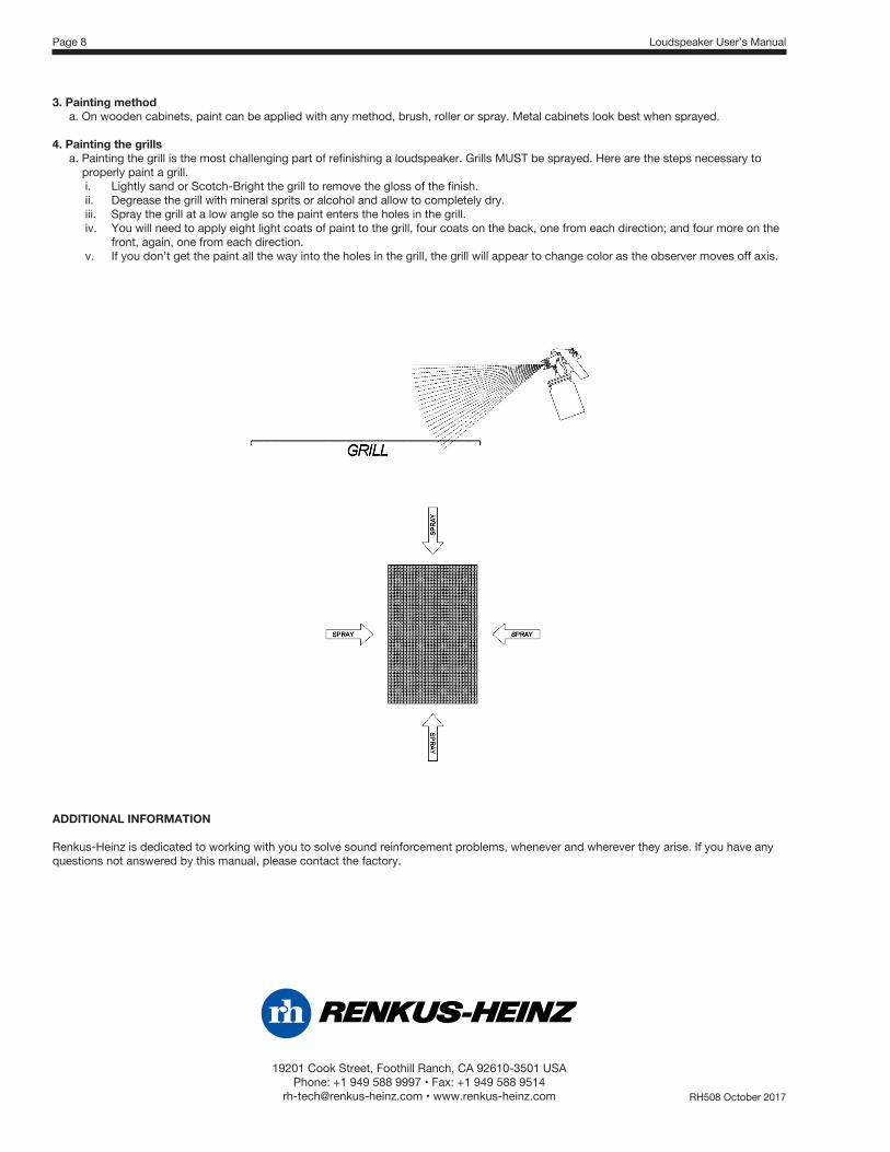
4. Painting the grills a. Painting the grill is the most challenging part of refinishing a loudspeaker. Grills MUST be sprayed. Here are the steps necessary to properly paint a grill.
i. Lightly sand or Scotch-Bright the grill to remove the gloss of the finish.ii. Degrease the grill with mineral sprits or alcohol and allow to completely dry.iii. Spray the grill at a low angle so the paint enters the holes in the grill.iv. You will need to apply eight light coats of paint to the grill, four coats on the back, one from each direction; and four more on the
front, again, one from each direction.v. If you don’t get the paint all the way into the holes in the grill, the grill will appear to change color as the observer moves off axis.
ADDITIONAL INFORMATION
Renkus-Heinz is dedicated to working with you to solve sound reinforcement problems, whenever and wherever they arise. If you have any questions not answered by this manual, please contact the factory.
19201 Cook Street, Foothill Ranch, CA 92610-3501 USA Phone:+19495889997•Fax:+19495889514
[email protected]•www.renkus-heinz.com RH508 October 2017