Embed Size (px)
Citation preview
Louisville Gas and Electric Company State Regulation and Rates 220 W. Main Street PO Box 32010 Louisville, Kentucky 40232 www.1 ge-ku xom
Mr. Jeff DeRouen, Executive Director Kentucky Public Service Commission 21 1 Sower Boulevard Frankfort, IiY 40601
PUBLIC SERVICE August 17, 201 1 COMMISSION Rick Lovekamp
Manager, Regulatory Affairs T 502-627-3780 F 502-627-3213 [email protected]
RE: In tlie matter of Louisville Gas aizd Electric Company Alleged Failure to Comply with KRS 278.042 - Case No. 2011-00098
Dear Mr. DeRouen:
Enclosed please find the following in connection with the settlement of the above referenced matter:
a check in the amount of $2,500.00;
field audit reports for the three months preceding and three months following the incident. The audit reports are being supplied subject to a Petition for Confidential Protection being filed herewith;
documentation of refresher training given to Team Fisliel employees as a result of the incident.
submission of the above LG&E has fully complied with tlie obligations set forth in the Settlement Agreement. Accordingly, the additional suspended $2,500.00 fine should be waived and the matter closed and removed from the Commission’s docket pursuant to paragraph 9 of the Agreement.
Should you require anything further, please contact me at your convenience.
Sincerely,
Rick Loveltainp
Enclosures
1366 Dublin Road
Columbus, OH 43215
(614) 274-8100
DIANE KEELER Chairman
JOHN PHILLIPS President and CEO
RANDY BLAIR Executive VP and COO
SCOTT HOMBERGER VP, Mldwest Region
BILL PAULEY VP, Western Region
SCOTT KEELER VP, Central Region
PAUL RlEWE VP and CFO
GREG GRABOVAC VP and General Counsel
KEN KAT2 VP and CIO
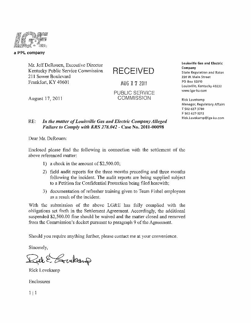
August 15, 201 1
Kelly Gibson Paralegal LG&E and KU Energy, LLC 220 West Main Street Louisville, Kentucky 40202
Dear Kelly:
By now you have received, under separate cover, the training materials you had requested involving the Operator Safety Training for the Altec Digger-Derrick Truck. It is Team Fishel’s commitment to ensure that this training is reviewed on an annual basis with all of our Teammates who are required to operate a Digger-Derrick for Team Fishel.
Please feel free to contact me if you have any further questions.
Craig S. Mathes Director of Safety & Human Resources
CSMlcsm
cc: Rick Druin Rich Mauldin
With Offices in ATLANTA CINCINNATI COLUMBUS DAllAS DAMON HOUSTON INDIANAPOLIS LOUISVILLE 0 LAS VEGAS LOS ANGELES
NASHVILLE * ORLANDO PHOENIX RICHMOND SAN DIEGO TAMPA * TUCSON * WASHINGTON DC
w. teamf i she l . com
. _ -
SENT am Professional ODerator
. .. ._ . .
Altec SENTRYm Program Professional Operator Safety Training
Altec Digger Derricks Operator Workbook
Table of Contents
Introduction., ................................................................................. The Altec Digger Derrick Operator Safety Program ................. Before You Begin .......................................................................... Certificate of Completion ............................................................ Sending Data to Altec .................................................................. Learning Objectives ..................................................................... Resource Material ........................................................................ Module 1 ........................................................................................ Module 2 ........................................................................................ Module 3 ........................................................................................ Module 4 ........................................................................................ Module 5 ........................................................................................ Module 6 ........................................................................................ Module 7 ........................................................................................ Module 8 ........................................................................................ Module 9 ........................................................................................
Appendix B - Daily Pre-Operational Component
Appendix C - Typical Altec Digger Derrick
Appendix A - Product Safety Labels ...........................................
Inspection and Diagram ...........................................................
Component Identification ........................................................
1 1 1 1 1 2 3 4 8 9 11 12 '1 4 17 19 22 23
33
34
Disclaimer: 'The material presented in this training program is intended to assist persons in understanding the basic concepts of safe and efficient operation of Altec Industries, lnc. digger derricks. This program is not intended to license or certify any person as an operator of an Altec digger derrick nor does it indicate that the operator is either skilled or authorized by Altec Industries, Inc. to operate digger derricks. The certificate of completion indicates that the person has completed this program.
All Rights Reserved: No part of this publication may be reproduced ar used in any form by any means graphic, electronic, or mechanical, including photocopying, recording, taping, or information storage and retrieval systems - without the written permission of Altec Industries, Inc.
0 2002 Altec Industries, Inc
OPERATOR WORKBOOK
1 ntroduction This training program provides rules and practices of sate operation for ill1 people who use Altec digger derricks. This course alone will not certify you to become a Factory authorized operator of an Altec digger derrick. It is intended as part of the training you will receive to make you a more safety conscious digger derrick operator.
Please read the disclaimer found on the title page of this workbook. Review the learning objectives found on page 2 to familiarize yourself with the impor- tant topics you will learn.
The Altec Digger Derrick Operator Safety Program
A CDROM provides the training materials which are the basis for the program. The program consists of a series of nine instruction modules. Various forms of multimedia formats including video, narrative, and graphic illustrations are used to convey the material. When the material being presented has relevance to an OSHA regulation, a citation from that regulation appears on the screen. A link to the complete OSHA regulation is also provided.
At the end of each module the program conducts a short quiz based on the material you just learned. If you are using this program without an instructor. the CDROM program will automatically conduct the quiz. If an instructor is conducting the program, you will be given an answer sheet to till out.
You are expected to answer each question correctly before you proceed to the next question or training module. If you click an incorrect answer, the program will ask you to review the information. If you click an incorrect answer the second time, the program will automatically present review material before you have another chance to answer the question.
After you complete the quiz, for the ninth module you will take a twenty question examination that tests your understanding of all subject areas.
The Opeiator Workbook contains a summary of the material presented on the CDROM. Material is presented so you can follow along during the presentation and also use it for future reference.
Before You Begin I f you are using this program without an iiutriictor make sure you read tlze “ReadiMe.pdf’ or “ReadMe - DD.pdf ’file contained on tlze CDROM. It contains valuable information oiz loading and rising the program. It also lists the rnirtimiiin computer hardware requirements.
Certificate o Completion
Sending Data to Altec
You will receive a Certificate of Completion from Altcc after you send them your demographic and test data. Make sure your employer signs the “Employer Signature” and “Instructor Signature” blanks. Also the Performance Evaluator must sign the certificate to complcte your operator training.
Refer to the “ReadMe.pdy’ or “ReadMe - DD.pdy’Jile contained oil the CDROiM for complete iitstructiorishw serrdirig your data to Altec Industries, Imtc.
Pas$ I
Learning Objectives Aftcr participating in the A i m SENTRY Prq i -mz fiw dig<yor derricks you should be able to:
1.
7 - *
3.
4.
5.
6.
7 .
8.
9.
10.
I I .
12.
13
Understand the purpose and use of d l manuals.
Understand that manuals are integral parts of a digger derrick and shuuld he stored on the unit.
llnderstand the safety statements found on an Altec digger dei-rick and associated manuals.
Understand the hand signals used to communicate with an Altec digger derrick operator.
1Jnderstand OSHA regulations that pertain to the operation of digger derricks.
[Jnderstand the items you need to inspect on a daily basis hefore you start out for the job including checking pins. fiisteners, welds, and hytfrauiic cylinders. hoses and tubes.
Understand how to prepare for travel to the jobsite including, checking the running gcar, checking clearance heights to overhead obstructions, and safely parking your unit.
Understand how to examine the job site for potential hazards such as overhead obstructions and power lines. You should also be able to determine who is qualiiied to work on energized power lines and equip- ment, and select personal protective and fall protection equipment that meets the requirements of ANSI, OSHA, and your employer.
Understand the procedures needed to complete an Altec digger derrick preflight inspection including checking the slope, setting the outriggers, and checking all lower and upper control functions.
Understand the potential hazards of working on energized power lines and equiprncnt including the electrical continuity of the boom tip, insulating properties of the booms and the use of personal protective equip men t .
Understand var ious potential hazards and procedures when you operate a digger tierrick including how to avoid contact with energized power conductors or equipment.
Understand the proper procedures necessary to lift materials with ;I digger derrick including understanding how to use the various load charts found on an Altec digger derrick.
Underst;inct the correct procedures for operating the digger function including unstowing ;ind stowing the auger.
OPERATOR WORKBOOK
Resource Material OSHA Regulations
‘The following OSHA regulations Form the basis of much of the content found in the Alter. SENTRY Program j u r digger clcrricks. The program contains a full copy of the OSHA regulations that was up-to-date at the time the CDROM was published. Make sure your CDROM version (found on the first screen that you see after the program loads) matches the one listed on www.aitec.com.
19 10.67 - Vehicle-Mounted Elevating and Rotating Work Platforms * 1910.180 - Crawler Loconiotive and Truck Cranes
19 10.268 - Telecommunications 19 10.269 - Electric Power Generation, Transmission, and Distribution
* 1926.453 - Aerial Lifts 1926.550 - Cranes and Derricks 1926.601 - Motor Vehicles 1926.952 - Mechanical Equipment
Additional OSHA information is available at www.oslia.gov.
ANSI A10.31 (1995)
Altec digger derricks are manufactured and tested to ANSI A10.31. This standard also describes the responsibilities of:
* Manufacturers Distributors and installers Owners and users
Operators Lessors
Some of the responsibilities described include operator training, operator’s manuals, and product safety hazard labels.
ASME B30.5 - Mobile and Locomotive Cranes (1994) ASME B30.6 - Derricks (1995)
These manuals contain the hand signals used by digger derrick operators. The “Extend Boom” and “Retract Boom” signals are found in ASME B30.5 and the remaining signals are in ASME R30.6.

OPERATOR WORKBOOK Module 1
Safety statements, Hand Signals, and OSHA Regulations
Operator Training
Operator safety training is mandatory for every individual who operates an Altec digger derrick.
This operator safety training program consists of:
Altec SENTRY Program l o r digger derricks.
Operator training on the specific digger derrick irsed in the workplace (provided by Altec or the employer) and the specific procedures and hazmds encountered in the workplace (provided by the employer).
Performance Evaluation (provided by the employer. A Perfonncince Evrilrtation Sheet for each trainee is provided with the Instructor Training Kit and SelfDir-ected Tmining Kit.)
I t is very important that trainees understand they must complete all three steps before they operate an Altec digger derrick.
Safety Statements
Safety statements are one of the primary ways to call our attention to the potential hazards associated with digger derrick operation.
This safety alert symbol appears with most safety statements. It means attention, become alert, your safety is involved!
Safety Alert Symbol
Danger Symbol
Danger indicates an irnminently haz,ardous situation which. if not avoided. will result in death o r serious injury- Danger is used in the most ex I re me si t w i t ions
WARNING Warning Symbol
Warning indicates a potentially hazardous situation which, if not avoided, could result in serious injury or death.
ACAUTION Caution Symbol
Caution indicates a situation that might result in a personal injury or property damage.
Notice Symbol
Failure to follow Notice instructions could cause damage to the equipment or cause it to operate improperly.
Product Safety Labels
Operators must read, understand and follow the information listed on all product safety labels and documentation. The Product Sqfet,y Label section contains the location and line drawing of each label. They are for a typical digger derrick and might differ from the ones installed on your niachine.

OPERATOR WORKBOOK Module 1
Safety Statements, Hand Signals, and OSHA Regulations (Continued)
Hand Signals
When you need to communicate to an operator of a digger deirick, use hnnd or radio signals to issue commands.
Make sure the ground worker and machine operator stay in plain sight of each other. Hand signals are illustrated on the following pages.
Hoist The Load Hand Signal
(With forearm vertical, forefinger pointing up, move hand in small horizontal circle.)
Lower The Load Hand Signal
(With arm extended downward, forefinger pointing down, move hand in small horizontal circles.)
Raise The Boom Hand Signal (Arm extended, fingers closed, thumb pointing upward.)
Lower The Boom Hand Signal (Arm extended, fingers closed, thumb pointing downward.)
Extend The Boom Hand Signal (Both fists in front of body with thumbs pointing outward.)
Page 5
OPERATOR WORKBOOK Modulei
Safety Statements, Hand Signals, and OSHA Regulations (Continued)
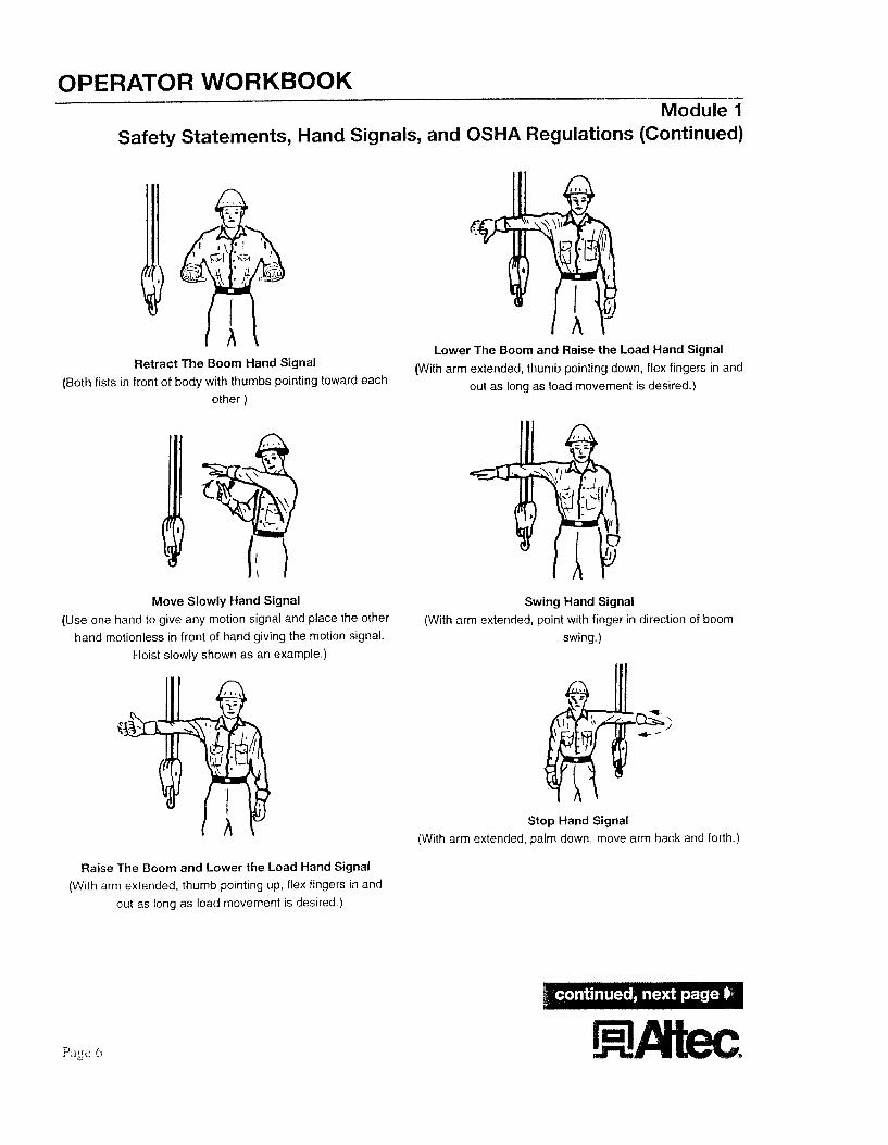
Retract The Boom Hand Signal (Both fists in front of body with thumbs pointing toward each
other )
Move Slowly Hand Signal (Use one hand to give any motion signal and place the other
hand motionless in front of hand giving the motion signal. Hoist slowly shown as an example.)
Lower The Boom and Raise the Load Hand Signal (With arm extended, thumb pointing down, flex fingers in and
out as long as load movement is desired.)
Swing Hand Signal (With arm extended, point with finger in direction of boom
swing.)
Stop Hand Signal (With arm extended, palm down, move arm back and forth.)
Raise The Boom and Lower the Load Hand Signal (With arm extended, thumb pointing up, flex fingers in and
out as long as load movement is desired )

OPERATOR WORKE300K Module 1
Safety Statements, Hand Signals, and OSHA Regulations (Continued)
Emergency Stop Hand Signal (With both arms extended, palms down, move arms back
and forth.)
Dog Everything Hand Signal (Clasp hands in front of body.)
OSHA Regulations
During the CDROM presentation, we make references to various OSHA regulations. Citations for a particular reference are displayed on the left side of your screen. When an OSHA regulation is cited, an “OSHA” button appears on the bottom of your screen so you can see the context of the regulation being cited.
When you are finished looking at the regulation, press the “RIETURN” button.
Page 7

OPERATOR WORKBOOK
Daily Unit Inspection
Before you travel to the jobsite make sure you:
Inspect the tires - the capacity and stability of a digger derrick is affected by the chassis tires.
Inspect the chassis fluid levels .I as reconmended by manufacturer.
Engine oil and hydraulic fluid checks are especially important.
Inspect for fluid Ieaks - especially hydraulic fluid.
If you find a hydraulic leak, contact the qualified hydraulic mechanic designated by your employer. And remember, never use your hands to check for leaks on a pressurized hydraulic system. The fluid can become injected under the skin causing severe injury. Should this happen, seek medical attention immediately.
Module 2 Digger Derrick Daily Unit inspection
* Inspect the lights, flashers, turn signals and signal devices.
* Inspect the boom hinge pin and cylinder pins.
* Inspect the turntable.
* Inspect the frame bolts and other fasteners.
* Inspect the welds.
* Inspect the hydraulic cylinders, hoses and tubes to ensure that they are in place and show no evidence of damage, cracks or corrosion.
Inspect the synthetic load line and material handling attachments for wear or damage. All material handling hooks should have functional throat latching mechanisms.
Inspect the fiberglass boom structures, platforms, guards and liners for contamination, damage and scratches.

OPERATOR WORKBOOK
Before You Travel
When you load a truck for travel, check that:
All itenis are secured.
Bin doors are properly latched.
Outriggers are raised and boom is stowed and secure.
Never exceed the Gross Vehicle Weight Rating (GVWR).
GVW = Truck Weight + Digger Derrick and Body Weight + Tools and Cargo Weight
Check the clearance height of the vehicle relative to the overhead obstructions such as power lines and bridges. Preplanning your route of travel can help to avoid these types of obstructions.
Module 3 Trave I in g
Before You Tow a Trailer
When you tow a trailer, be sure that:
The towing vehicle, pintle hook and trailer are compatible.
The trailer tow bar eye conforms with SAE 5847 and all local and state roading requirements.
You inspect the trailer and pintle hook for wear and damage.
You don’t exceed the manufacturer’s rating or towing capacity of the vehicle, pintle hook or trailer.
You use safety chains of proper capacity in accordance with local, state and federal roading requirements.
All latching mechanisms are properly engaged.
All trailer lights and signaling devices are in place and operational. Some loads may require additional signaling devices depending on local, state or federal requirements.
Page 9

OPERATOR WORKBOOK
Backing
* If you must back up, ensure that your backup alarm is operational and use a rearview mirror.
0 R
* Use an observer to signal when it is safe to move. View the observer by using a mirror or other rearview device. Back slowly and always keep the observer in your view.
If you cannot see the observer, stop backing until they return to a position where you can see them.
Module 3 Trave I i n g (Con t i n u ed)
Parking
If you must park on a roadway, park on the right hand side of the road facing in the direction of traffic flow.
* Whenever possible, leave at least 15 feet between the edge of your vehicle and the traveled road surface.
If you must park closer, appropriate warning devices must be used. Depending on your employer’s recommendations, and local, state or federal requirements, this may include warning lights, reflectors, warning signs, traffic cones, flags or a flag person.
* Before you leave the vehicle, remember to set the parking brake and chock the wheels.

OPERATOR WORKBOOK
Job Briefing
When you arrive at the job site, OSHA requires that the employee in charge of the work, hold a job briefing before the start of each job. The briefing must cover:
Job hazards.
When you conduct a job briefing, walk around the job site and identify the location and voltage of overhead power lines. Note that only qualified employees may approach within ten feet of any energized line. See the discussion on QunliJfed Employees.
Work procedures.
Special precautions.
When working on or near energized conductors or equipment, be sure to use appropriate cover up procedures and insulating materials and tools rated for the line voltage. And discuss any additional potential hazards associated with the tasks at hand.
Energy source control.
Module 4 Job Briefing
Your job briefing should include discussions about personal protective equipment required by ANSI, OSHA, and your employer which may include clothing as well as head, eye and fall protection, insulated gloves and sleeves, and leather gloves.
Qualified Employees
A qualified employee is one who has been designated by their employer as trained and familiar with the safety related work practices, procedures and other safety requirements of OSHA which pertain to their respective job requirement.
This includes competency in the skills and techniques necessary to distinguish exposed live parts from other electric equipment as well as the ability to determine the nominal voltage of exposed live parts.
A qualified employee must also be trained and competent in the skills needed to determine the minimum approach distances specified by OSHA as well as the special precautionary techniques, insulated tools, equipment and lockouthag out procedures necessary for working near exposed energized parts.
Personal protective equipment.
Page 1 1
. -- OPERATOR W RKBOOK - --__.
Module 5 Unit Setup & Pre-Operational Inspection
Operating On Slopes
Digger Derricks manufactured and tested to ANSI A10.3 1 are limited to their rated capacity with the unit set up on a maximum of a five degree slope. Unless appropriate measures to level the unit are taken, you should never operate a digger derrick on a slope of over five degrees. This is especially true of operations that include rotation of the boom over the side of the chassis.
If the job site iricludes an area where the slope exceeds five degrees, or excessive ground penetration is observed, appropriate cribbing and blocking of outriggers may be required.
P re - 0 pera t i o n a I I ns pec t ion
A pre-operational inspection (also called preflight inspection) must be performed before you use the machine.
Remember, never exceed the unit's rated capacity. Overloading the derrick boom can result in structural damage, instability or both
Check the hydraulic reservoir oil level.
Check for hydraulic leaks.
Check pins.
Check fasteners.
Check welds.
Check hydraulic cylinders, hoses and tubes.
Check visual and audible warning devices.
Inspect fiberglass boom structures, platforms and liners for dirt and damage.
Apply the parking brake, place the wheel chocks, start the engine and engage the power take off.
Barricade or ground the unit if required by your employer.
Properly set all outriggers before the derrick boom is moved from the boom rest.
- During deployment, outriggers being extended should be kept in full view to be sure path is clear of other individuals.
- Outrigger pads are required on all unpaved or soft surfaces, or in accordance with your employer's work practices.
- They should be set on the downhill side first and should extend at least three to four inches after contacting the ground. In addition, the chassis tires should unload noticeably, but may remain in contact with the ground.
OPERATOR WORKBOOK Module 5
Unit Setup & Pre-Operational Inspection (Continued)
* Perform a pre-operational check from the Perform a pre-operational check from the lower controls: upper controls (if equipped):
- Be sure the area is free from overhead obstructions such as trees, poles and power lines.
- Operate the unit through the range of all functions to ensure proper operation.
I When you operate the unit from the lower controls, be sure that you and others are clear of moving structures. -
- On units equipped with platforms, test the override system at the lower control station. The lower controls should override the function of the upper controls.
- Return the boom to the boom rest.
If the unit has a platform, orient the platform near the ground for platform access.
OSHA regulations and ANSI standards require that personal fall protection equipment be used and attached to the unit’s fall protection anchor points. Prior to entering the platform to test the upper controls, be sure you are using approved personal fall protection equipment that you have inspected for damage.
Make certain the upper control selector functions (also called the emergency stop button) stops system operation.
Page 1.3
OPERATOR WORKBOOK Module 6
Unit Operation
Personal Protective Equipment
Before you begin your job, check the condition of all protective clothing and equipment as required by ANSI, OSHA and your employer.
Sources of Insulation
It is important to note that when working from an insulated digger derrick, the boom is not the operator’s primary source of insulation.
Personal protective equipment required by ANSI, OSHA, and your employer is your primary source of insulation. You must use proper protective equipment, rated for operations within the OSHA defined approach distances.
When units are equipped with an insulated boom, the upper boom should always be extended first for dielectric protection.
Electrical Continuity of the Boom-Tip
Follow the guidelines listed below as well as the special guidelines in the Safety Bulletin shown on the next page:
When operating a digger derrick from a boom tip platform, all components at the boom tip, including the controls, must be considered to be electrically connected.
If an energized conductor or object touches any part of the boom tip, treat the entire boom tip as energized.
If any ground conductor or object touches any part of the boom tip, consider the entire boom tip as grounded.
The insulated portion of the boom can only isolate the operator from grounding through the boom and vehicle.
The pole, cross arm and other hardware must be considered by the operator as grounded.
The unit can’t protect a person from current between an energized conductor and any other conductor, ground or grounded equipment on or in contact with the pole including the neutral wire.
OPERATOR WORKBOOK Module 6
Unit Operation (Continued)
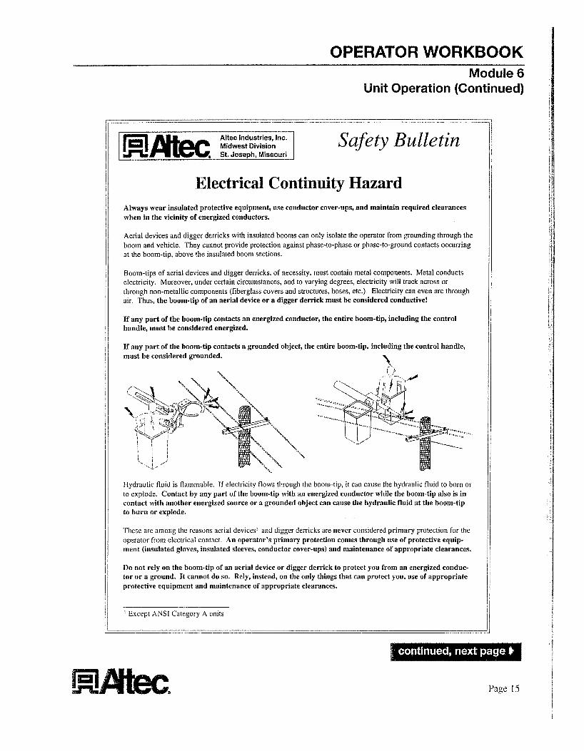
Midwest Divlsion Safety Bulletin ,,,-St. Joseph, Missouri _---
Electrical Continuity Hazard Always wear insulated protective equipment, use conductor cover-ups, nnd mnintnin required clearances when in the vicinity of energized conductors.
Aerial devices and digger derricks with insulated booms can only isolate the operator from grounding through the boom and vehicle. They cannot provide protection against phase-to-phase or phase-to-ground contacts occurring at the boom-tip, above the insulated boom sections.
Boom-lips of aerial devices and digger derricks, of necessity. must contain metal components. Metal conducts electricity. Moreover, under certain circumstances, and to varying degrees, electricity will track across or through non-metallic components (fiberglass covers and smctures, hoses, etc.). Electricity can even arc through air. Thus, the boom-tip of an aerial device or a digger derrick must be considwed conductive!
If any part of the boom-tip contacts an energized conductor, the entire boom-tip, including the control handle, must he considered energized.
If any part of the boom-tip contacts a grounded object, the entire boom-tip, including the control handle, iiiust be considered grounded.
liydraulic fluid is flammable If electncity flows through the boom-tip, it can cause the hydraulic fluid to burn or to explode. Contact by any part of the boom-tip with an energized conductor while the boom-tip also is in contact with another energized source or a grounded object can cause the hydraulic fluid at the boom-tip to burn or explode.
I'licse are among the reasons aerial devices' 2nd digger derricks are never considered primary protection for rhe operator from electrical contacr An operator's primary protection comes through use of protective equip- ment (insulated gloves, insulated sleeves, conductor cover-ups) and maintenance of appropriate clearances.
Do not rely on the boom-tip of an aerial device or digger derrick to protect you from an energized conduc- tor or a ground. i t cannot do so. Rely, instead, on the only things that can protect you, use of appropriate protective equipment and maintenance of appropriate clearances.
' Except ANSI Catcgory A units
Page 15
OPERATOR WORKBOOK Module 6
Unit Operation (Continued)
General Guidelines During Unit Opera tion
* When handling material, never attach the load to the fall protection anchor.
* Never lay conductors on platforms to lift them into position. And do not allow conductors or other objects to drag across the boom as this may cause gouges in the boom and compromise its strength, durability, and insulating properties.
* On units equipped with side load protection, never overload the side load protection system, as this can cause instability and/or structural problems.
OSHA Guidelines
* Only trained persons may operate the digger derrick.
Remember to calculate the minimum approach distances specified by OSHA for the nominal voltage of exposed parts. Refer to OSHA Regulation 1910.269, Tables R-6 through R- 10.
* Workers should never belt off to an adjacent pole, structure or equipment.
Workers must always stand firmly on the floor of the platform---.never sitting or climbing on the edge of the platform or using planks, lad- ders or other devices for a work position.
Workers should never wear climbers while working from a digger derrick equipped with a platform.
* You may use hydraulic tools connected to boom-tip outlets with nonconductive hoses as long as energized conductors are insulated with protective equipment that is rated, maintained and tested for the voItage involved. When the tools are not in use, but are attached to the tool circuit outlets at the boom tip, turn off the tool circuit.
OPERATOR WORKBOOK Module 7
Material Handling OSHA Guidelines
The following are OSHA requirements pertaining to material handling:
Operators must observe all manufacturer’s load ratings and instructions.
The rated load capacities and instructions related to derrick operations must remain posted on the unit.
Digger derricks and associated equipment must be inspected by a competent person at the manufacturer’s set intervals. And a complete record of inspection and repairs must be maintained.
You cannot make any modifications to a digger derrick which affects operation without manufacturer’s written approval.
The operator of a digger derrick may not leave their position at the controls while a load is suspended.
Synthetic ropes must be inspected in accordance with OSHA requirements and the recornmendations of the rope manufacturer.
When you set, move or remove poles, all necessary precautions should be taken to avoid contact with energized power conductors or equipment. When poles are being placed or moved during heavy rains, sleet or wet snow, additional safe work practices may also be required for certain workers and voltages.
Maintain minimum approach distances from exposed energized lines and equipment. Refer to OSHA Regulations 1910.269 Table R-6 through R- I 0.
Material Handling
6 A designated person, other than the operator, may be required to observe the approach distance to exposed lines and equipment. The designated person must give timely warnings before the minimum approach distance required by OSHA is reached.
Avoid Contact With An Energized Power Conductor
You should take special precautions when you work with energized power conductors or equipment:
If the pole you are working on could come in contact with an energized power conductor:
- Wear insulating gloves when you handle the pole with your hands or tools.
._ The truck should be considered energized and special precautions are needed to avoid electrocution.
When you are on a digger derrick vehicle, avoid all contact with the ground, with persons standing on the ground and with all grounded objects such as people, tree limbs or metal sign posts.
If you can, stay on the vehicle as long as the possibility of contact with an energized power conductor exists.
When the digger derrick may come in contact with energized lines, and i t is necessary to leave the vehicle:
- Step onto an insulating blanket and break all contact with the vehicle before hopping or shuffle stepping off the blanket and onto the ground.
1. If an insulating blanket is not available, jump cleanly from the vehicle and hop or shuffle step away from the unit.
Page 17
OPERATOR WORKBOOK Module- 7
aterial Handling (Continued)
Avoid Contact With Energized Equipment
If you are working on equipment that could become energized:
OR
* Protect each employee from hazards resulting froin equipment contact with the energized lines. Protective measures must include:
-
The exposed lines must be covered with appropriate insulating protective material.
OR
* Using the best available ground to minimize the time the lines remain Insulate the equipment for the voltage
involved. energized.
AND - Bonding equipment together to minimize potential differences.
Providing ground mats to extend to areas of equipotential.
LJsing insulating protective equipment or barricades to guard against any remaining hazardous potential differences.
Position the equipment so that its uninsulated portions cannot approach the energized lines or equipment closer than the specified miniiiium approach distance.
-
-

OPERATOR WORKBOOK Module 8
Load Capacity
Load Capacity OSHA Guidelines
The following are OSHA requirements pertaining to load capacity:
* Stay within the maximum load rating and other design limitations for the conditions under which the work is being performed.
Load capacities shown on the Load Capacities Chart are for an Altec digger derrick operating on a level surface.
Before you lift a load, consult the Load Capacities Chart, Jib Capacities Chart, or the Combined Use Capacities Chart. You may also need to use the Range Diagram to help determine which booms you need to extend.
The Load Capacities Chart is located near the lower contxol station, the Jib Capacities Chart is located at the platform, and the Combined Use Capacities Chart is Located near the boom tip.
Samples of these charts are shown on this page.
Combined Use Capacities Chart
-
Load Capacities Chart
Jib Capacities Chart
Range Diagram
Page 19

OPERATOR WORKBOOK
Using the Load and Jib Capacities Charts
Notes: The load and jib capacities churts are only iised if your Altec digger derrick doesn't have a platform or the platform is [(ti occrrp ied.
T h e charts are only for freely suspended loads.
To determine the load capacity of your Altec digger derrick:
Determine the load radius. Always measure the load radius from the centerline of rotation of the digger derrick to the center of the mass of the load.
If you use a material handling jib, make sure you take into account the actual load radius at the jib tip. Do not exceed the maximum Ioad radius shown in. the Load Capacities Chart when you lift a load with the jib.
Determine the boom angle.
If the actual load radius or boom angle is not shown on the chart use the load capacity at the next longer radius or lower boom angle.
If a boom stage is not fully retracted, use the load capacity for that boom when it is extended.
Use the Load Capacities Chart to determine the combination of boom to extend. You can also use the Range Diagram to help determine which boom(s) to extend.
Module 8 Load Capacity (Continued)
IJse the Load Capacities Chart to determine the load capacity at the load radius, boom angle, and boom combination you have chosen. The Ioad capacity must be adjusted as follows.
Never exceed the sntallest of:
- The load capacity shown on the Load Capacities Chart minus reductions for all options mounted on the boom.
- The winch line rated working load multiplied by the number of parts of line.
When the load being lifted exceeds the rated working Ioad for a single part of line, multiple parts of winch line must be used. Remember, the weight of the load, divided by the number of parts of line must not exceed the rated working load of the winch line.
- The rated capacity shown on the Jib Capacities Chart.
Combined Use Capacities Chart
If the unit's platform is occupied, refer to the Combined Use Capacities Chart instead of the load capacity chart.
No load is permitted on the winch line when the personnel jib is in use.

OPERATOR WORKlBOOK
Estimating the Weight of a Load
A load of unknown weight should never be lifted.
If you aren’t sure of the weight of the load you are attempting to lift, and you have estimated its weight, perform a boom capacity test to lift the load a small amount. This boom raise capacity test is described in your Altec Derrick Operator Mmzuul. But remember the boom capacity test does not test the unit’s stability. The L,oad Capacities Chart must be used to determine the unit’s stability.
Hydraulic Overload Protection System
Remember that the Hydraulic Overload Protection System (HOP) only protects the unit from structural overload, not instability. As previously stated, the Load Capacities Chart must be used to determine the unit’s stability.
Module 8 Load Capacity (Continued)
Safety Procedures for Material Handling
The following safety procedures should be observed when you handle material.
Never use the material handling load line to lift personnel, to lift loads over personnel or to lift loads which are still attached or stuck to the ground.
Never drag loads or side load the boom and never try to override the side load protection system.
Operate all controls smoothly and make sure controls are returned to neutral after the desired operation.
Always use rigging and slings which are in good condition and carry tags giving their rated capacity.
LJse tag lines only where appropriate.
Never allow the load to come in contact with the boom tip, except when placing poles using the boom tip pole guide.
Page I! I
OPERATOR WORKBOOK Module 9
Digger Operation
Unstowing and Using Your Auger
1.
2.
3.
4.
5.
6.
7.
8.
9.
The first thing to remember is to always call your local, and/or state digging safety, or under ground line locator, service prior to digging.
Before you unstow the auger, fully retract the boom.
Raise the boom to approximately 45 degrees.
Rotate the boom to a position where the potential swing area of the auger is clear of personnel and obstmctions.
Carefully move the AIJGER (DIGGER) control to the DIG position with the engine at low RPMs. This will take up any slack in the wind up cable and decrease the load on the auger stow latch.
Operate the AUGER RELEASE switch to retract the auger stow latch.
Continue holding the switch in this position while slowly actuating the DIGGER control to the CLEAN position, carefully lowering the auger into a vertical position.
When the auger has descended to its vertical position, remove the wind up cable from the auger flight.
If your unit is equipped with a two-speed diggcr, select high or low speed before operating the digger. The auger must be at a complete stop before shifting speeds.
10. Extend the boom approximately 1-1/2 ft (0.5 m) to meter the boom extension control so the auger stays aligned. A straight hole cannot be dug if the boom is fully extended or retracted. The boom control is used to lower the boom as i t digs.
11. Maintain enough force on the auger to keep it moving downward at a moderate rate of speed. Too much force may result in the auger corkscrewing into the ground rather than digging and could overload the boom and cause machine damage.
12. When you clean the auger, operate it in reverse by putting the DIGGER control in the CLEAN position. Use the DIGGER SHAKE switch to help clean the digger.
Stowing Your Auger
1.
2.
3.
4.
5.
6.
7.
Attach the wind up sling.
Slowly raise the boom. Be sure the potential swing area of the auger is clear of personnel and obstructions.
With the digger in low speed, operate the AIJGER REL,EASE switch to retract the auger stow latch.
Continue holding the switch in this position and move the DIGGER control to the DIG position. The auger will begin to wind onto the sling and towards the latch bracket.
Meter the DIGGER control slowly and carefully as the auger nears the bracket. The digger has enough power to break the cable or strap if the control is fully actuated as it is rewound.
Once the auger has been returned to the stow position, disengage the AIJGER RELEASE switch to close the auger latch.
Meter the DIGGER control very slightly to the CLEAN position just enough to release the stress on the wind up cable.
i
OPERATOR WORKBOOK Appendix A - Product Safety Labels
Product Safety Labels
This section of the manual contains typical product safety labels for Altec digger derricks. The first few pages contain diagrams that show where the labels are located. Each drawing is indexed with the product safety label that belongs there. Illustrations of the product safety labels are on the pages that follow the location diagrams. The part number to order a complete set of these labels is 750-40097.
I
Page 23
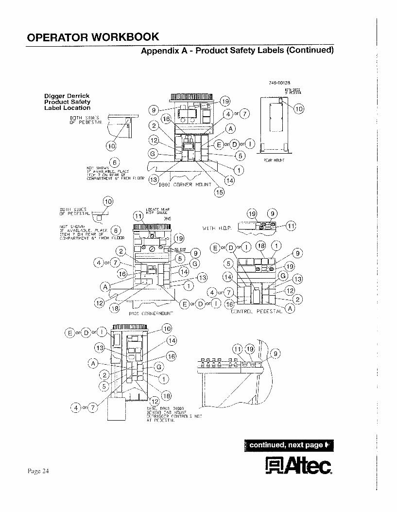
OPERATOR WORKBOOK Appendix A - Product Safety Labels (Continued)
749-00128
Digger Derrick Product Safety Label Location
BOTH SIDES flF PEDESTAL
NOT SHOWNL’ It- AVAILABLE. PLACE ITEM 7 ON REAR O f COMPARTMENT 6’ FROM FLOOR
REAR MOLlNT
S NO 1
Page 24

OPERATOR WORKBOOK I I Appendix A - Product Safety Labels (Continued) I
NUN UPPER CONTROLS 13842, 0845, 0945, D947
2 HANDLE NUN-PIJLLOIJT D800. D900, DlOOO
2 HANDLE NUN-PULLOUT D842, D845. UY45, D947
4 HANDLtT NON-PUL l..DUT DE42 E845 D945, D947
749-00128
4 HANDLE PULLOlJT 1090 SERIES
2 HANDLE PIJLLOUT 1090 SERIES
2 HANDLE PIJLLOUT D842, D845, D945, 0947
j. HANDLE PULLUUI P842, D845, D945, D9a7
Page 25
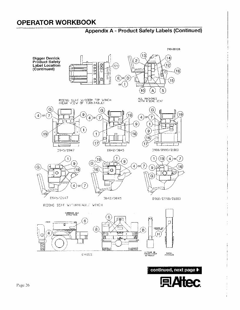
OPERATOR WORKBOOK _--- __--_-..-I
Appendix A - Product Safety Labels (Continued)
Digger Derrick Product Safety Label Location (Continued)
R I D I N G SEAT W / B U O M TIP W I N C H (REAR VIEW OF TURNTABLE)
749-001 28
(3 or
ALL MACHINES W I T H R I D I N G S E A T
D945/D947 D 900 / D 9 90 / Dl000
’ 0945/0947 D842/D845
R [DING SEAT W/T IJRNTABLE W I N C H
A
I
OPERATOR WORKBOOK Appendix A - Product Safety Labels (Continued)
749-00128
Digger Derrick Product Safety Label Location (Continued)
r Both Sides
of Tip c
ALL UNITS W I T HOU T P L A T F 0 R I4 MOIJNTIFIG TUBES
C942. D845 IJNITS O N L Y Digger Derrick Product Safety Labels
,--------------" -
4N UNTRAINED OPERATOR SUBJECTS HIMSELF AfiD
OTHERS TO DEATH OF! SERIGUS II\IJUPI
PLATFCIPM-S rEFSlDE
@)' AIJGER STO'JAGE Bolh Sides DKACKET of Bracket
A fvlOVlNG OlJTRlGGER CAN CAUSE
SERIOUS CRUSHING II.IJ!JRY Do not opero te a n y ourrigger t inless ycu or (I signol person con ciee thot personnel and cbst 'ructions ore C l e m o f the outrigger and 11s con tac t point 1-670-40229
OPERATOR WORKBOOK Appendix A - Product Safety Labels (Continued)
749-001 28 Insulated Aerial Device Product Safety Labels (Continued)
DANGER
DEATH OR SERIOUS INJURY W I L L RESULT FROM CONTACT V I T H OR INADEQATE
CLEARANCE TO ELECTRICAL POWER LINES AND APPARATUS.
h i n t a n sofe c l e a r a x e s f r a electrical povw ines in accordance with opplicaMe governnent wylations. N~OR for boon, plotfwn, 4ectric line and load lip sroy :his nachine does n o t provide proiectlcn ' ron contact i t h or proxhity t o on 4ectricolly charged power ine. 670-40181 8 --.__-
Conductive Hoses W i l l Cause DEATH OR SERIOUS INJURY Use only hose labelled non-conductive o n tools platform area
in the insulated sections and 1-670-40290
A DANGER
ELECTROCUTION HAZARD DEATH OR SERIOUS IWURY
W N RESULT FROM CONTaT W N OR IWEOUATE CLEWAWE FROU ELECIRICK Wwul UPES ru.c)
wpPwnis
ALL COMPONENT5 AT nwI BOOM TIP. INCLUMNC THE CONTROLS. MUST BE CONSIDERED AS
ELECIRIC.AI.LY CONNECTED.
b i s mi! rriU not provide omtectim from :ontact vith oi proximity i o on eisct~kolh/ h r g c d pcwer line when you a (he cornpanenti 11 Va boom tip am in contad with (x in ~roximity Io anolher power line. ground. or ode 411 rnstd and f l b e I g l ~ 8 components ot the ,oam tip. includnq the canWolo. moy bccarne ansrpizsd
Maintain sofa clearonces from elsclncd power i- in occodoncc with opplicobl. gov-nt q U a t k n e m d aafa work pmctioeo Allow f(x m m . plotform. cledn'c line. and Imd line w m y
f the possibility of dcclrk contad exist,. Vperaton m u d use proper protective equipment w h 03 hzulotinp rubber #ores and SIC-. 701 sticks. conductw cover up, and plotform inen
670-.0117 E
OUTRIGGER CONTACT WILL CAUSE SERIOUS CRUSHING
INJURY
STAND C L E A R 2-870-40170
i

OPERATOR WORKBOOK - Appendix A - Product Safety Labels (Continued}
Insulated Aerial Device Product Safety Labels (Continued)
749-001 28
,
___-- - ___ ELECTROCUTION HAZARD
DEATH OR SERlOlJS INJURY WILL RESULT FROM CONTACT WITH OR INADEOUATE CLEARANCE
FROM ELECTRICAL POWER LINES AND APPARATlJS ALL COMPONENTS AT THE BOOM TIP INCLUDING THE CONTROLS
MUST BE CONSIDERED AS ELECTRICALLY CONNECTED
Mainlain sale clearances lrom electrical power lines in accordance wilh applcable government regulations and sale work piaclices Allow lor boom platform eleclric line and load line sway
I1 ihe possibility 01 electric coniact exists operators must use proper proleclive equipmenl such a5 insulaling rubber glows and sleeves hot slicks conductor cover up and plartorm liners
DEA?M OR S E R I O U S INJURY COULD RESUL? FROM SLIPS
AND FALLS DO NOT USEVHIS AREA
AS A STEP
P:rii,c?) SUEP ---w111)
DEATH OR SERlOlJS INJURY COULD RESULT FROM FALLING
WHEN MHICLE IS IIN MOTlOM ALL RlfJERS MUST BE IN CAB
WITH S A E W BELVS FA§V[ENED
a70 m z e 4 ~ NO RUDER ._____-__ _.____
These two placards are not used in specific positions. CJse as required.
OPERATOR WORKBOOK -- Appendix A - Product Safety Labels (Continued)
Digger Derrick Product Safety Labels (Continued)
. __ ~-
FAILURE TU UUEY I H K t -uLLnw[rxi w i t L RESULT ~ E I
UERlH OK SERIOUS IN,IURY
L70-10105 ~ . - ~ - Far units with an insulated Aating
I
For units with an Non-Insulated
Rating
749-00128
... /"--- _ _ - _ _ _ \
D E A T H CIR SER[flI.IS IN,lURY 1 p e r s o n s a r e r l e n r of the a rea . II ' ~ . __/
.Never stow a n oi.rger until nll
1-670-40205 ,---- L
DO NUT USE PLATfURM UN THIS
AND C O M B I N E D DERRILK I PLATrURM USE' L O A D i A P A C i T Y CHART HAS
670 4U301 ____-_
-OD ti01 A T I C Y P I 10 R O l h l E i t € DERRICK 4Whl i R W A l l EXTCRIiAL SIDE LOAD RFf'LiED B Y rHE V I N L H flP
lt€ s i U~GCER iHis .xi int i WILL CS~ICEL
2-670-40i60
OPERATOR WORKBOOK Appendix A - Product Safety Labels (Continued)
-.-_
Digger Derrick Product Safety Labels (Continued)
749-00128
......... ___
I -6 ,‘0 --I 01 6 3 ,),I --
I i I i I
..........

OPERATOR WORKBOOK Appendix A - Product Safety Labels (Continued)
uigger uerrictc Product Safety Labels (Continued) 1 1
TWO @LCCKIFIG I I i E UNIT WII I. RESlJLT IN
DEATH OR SERIOUS INJURY 00 ilol alhu the hook MPd( IO conlad Ihe bwm Io by haslirq up, crtcndng w lowennq the bwm 670-40732
DO NOT M A N U A L L Y R O T A T E BOOM PAST STOW POSITION. HOSE DAMAGE WILL R E 5 U L T
749,00128
A CAUTION
i
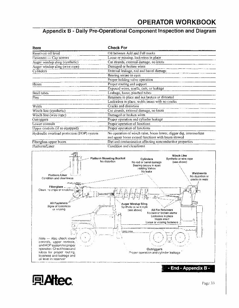
RKBOOK Appendix B - Daily Pre-Operational Component Inspection and Diagram
--._).
.- Platform Mounting Bracket Cylinders Synthetic or wire rope No distortion No rod or barrel damage (see above)
Bearing secure in eyes \ I, ~ Holding Valves \ I/ I No leaks '\ Weldments
Item Check For
-I_--
Reservoir oil level Fasteners - Cap screws
Auger windup sling (wire rope) Cy I i n ders
Oil between Add and Full inarks Loose or missing, lockwires in place Cut strands, external damage, no knots Damaged or broken wires External leakage, rod and barrel damage Bearing secure in eyes Proper holding valve operation
Exposed wires, scuffs, cuts, or leakage Steel tubes - L.eakage, loose, pinched tubes
Retainers in place and not brokenor distorted Pins Lockw&s in place, welds intact with no cracks
Welds Cracks and distortion Winch line (synthetic) Cut strands, exjknal damage, no knots Winch line (wire rope) Damaged or broken wires Gutri,g 0 ers Proper operation and cylinder leakage Lower controls Proper operationof functions
Proper operation of functions Upper controls (if so ecFppe(j) Hydraulic overload protection (HOP) system No operation of winch raise, boom lower, digger dig, intermediate
and upper boom extend functions with boom stowed Dirt and contamination affecting nonconductive properties Fiberglass upper boom
PlatformLiner Condition and cleanliness
--. Auger windup sling (synthetic) I.I _-_-
-__-____ - ~ - - - -. -- ____ _ . l _ _ _ _ _ _ - ~ ~ _ _ _
.-- -__ ~ - - - - uoses Proper __-. routing a;;;;i support I
-. - - __
~ _ l _ _ _ _ l _ _ _ _ l ~ I
-_ -
---,-
__ ~ _ _ _ I _ ~
I _I___-
Page 3 3
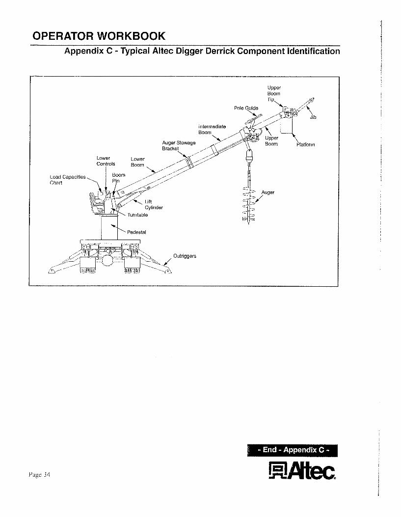
OPERATOR WORKBOOK Appendix C - Typical Altec Digger Derrick Component Identification
Intermediate
Auger Stowage Boom Platfarrn Bracket
\ ,/'
In the
COMMONWEAL
JUG 1 7 2019
atter of: PUBLIC SERVICE CQMMISSIOT\I
) COMPANY )
) _I )
)
CASE NO. 2011-00098
FAILURE TO COMPLY WITH KRS 278.042
OUISVILLE GAS AND C COMPANY AL PROTECTION OF INFORMATION
PONSE TQ THE COMMISION’S ORDER OF JULY 26,2011
Louisville Gas aiid Electric Company (“LG&E” or the “Company”) pursuant to 807 KAR
5:OO 1, Section 7, respectfully petitions the Cornniissioii to classify as confidential and protect
froin public disclosure certain safety audit reports. These documents, in their entirety, contain
critical energy infrastructure inforination and private personal information about some Company
employees or contractors, such as their names, telephone numbers, aiid eniployee ideritificatioii
nurnbers. For reasons irivolving homeland security and personal privacy, the Company
respectfblly requests that tlie Coinmissiori grant coiifideiitial protection to these documents.
In further support of this Motion, tlie Company states as follows:
1. Under the Kentucky Open Records Act, the Coinmission is entitled to withhold
from public disclosure information confidentially disclosed to it to the extent that open
disclosure would “have a reasonable likelihood of tlu-eatening the public safety by exposing a
vulnerability in preventing, protecting against, mitigating, or responding to a terrorist act and
limited to: . . . (0 infrastructure records that expose a vulnerability referred to in this subparagraph
tlirougli tlie disclosure of the location, configuration, or security of critical systems, including public
utility critical systems. These critical systems shall include but not be limited to information
technology, communication, electrical, fire suppression, ventilation, water, wastewater, sewage, and
gas systems and (8) tlie following records wlieii their disclosure will expose a vulnerability referred
to in this subparagraph: detailed drawings, scliematics, maps, or specifications of structural elements,
floor plans, aiid operating, utility, or security systems of any building or facility owned, occupied,
leased, or maintained by a public agency.” Succinctly put, the
information contained in the attached safety audit reports may provide detailed information about
tlie Company’s distributions system; as sucli, tlie disclositre of which could threaten the public
safety generally.
2.
See KRS 61.878( l)(in)l.
Under the Kentucky Open Records Act, the Coinniission is also entitled to
witldiold from public disclosure, “Public records containing information of a personal nature
where tlie public disclosure thereof would constitute a clearly unwarranted invasion of personal
privacy.” Coricei-niiig such personal and private information, the
Kentucky Attorney General has “affirmed agency denial of access to a public employee’s home
address, home telephone number, date of bii-th, aiid social security number. See, for example,
OAG 79-275; OAG 87-37; OAG 90-60: OAG 91-81; 94-ORD-91.”’
See KRS 6 1.878( l)(a).
3. The information contained these reports contains the addresses, telephone
numbers and employee identification numbers of several of tlie Company’s employees. This
information is private personal information that ought to be protected from disclosure to the
public, in accordance with tlie Attorney Geiieral’s opinions cited above.
4. The information for which tlie Company is seeltiiig confidential treatment is not
luiowii outside of the Company, is not disseminated witliin the Companies except to those
’ I n re: June Britton/L,exington-Fayette IJrban County Government, ICY OAG 00-ORD-090 at 3-4 (April 3,2000).
einployees with a legitiinate business iieed to h o w and act upon tlie iiiforination, aiid is
geiierally recognized as coiifideiitial aiid proprietary inforinatioii in tlie energy industry.
5. If tlie Coinmission disagrees with this request for coiifideiitial protection, it inust
hold an evidentiary heariiig (a) to protect tlie Coinpaiiy’s due process rights aiid (b) to supply the
Coiiiiiiission with a coiiiplete record to eiiable it to reach a decisioii with regard to this matter.
Utility Regulatory Coiiiinissioii v. Kentucky Water Service Company, Inc., Ky. App., 642
S.W.2d 591, 592-94 (1982).
6. The Company is filing with the Comriiission one copy of
Iiiforriiatioii identified as Confidential.
, Louisville Gas
Commission grant coiifideiitial protection
Dated: AugnstMii(20 1 1 1.7
and Electric Coinpaiiy respectfully
to tliese documents, in their entirety.
Respectfully submitted,
the Confidential
requests that tlie
Senior Coi-porate Couiisel LG&E and I W Energy LLC 220 West Main Street L,ouisville, Keiituclcy 40202 Telephone: (502) 627-2088
Couiisel for Louisville Gas and Electric Company