Embed Size (px)
Citation preview
Terry L. Chapp, PE For the International Association of Refrigerated Warehouses and the International Association for Cold Storage Construction
Low Ammonia Charge Refrigeration Systems for Cold Storage
White Paper
Copyright © 2014 by the International Association of Refrigerated Warehouses and the International Association for Cold Storage Construction
All rights reserved.
No portion of this work may be reproduced or transmitted in any form by any means, electronic or mechanical, including photocopying and recording, or by any information storage or retrieval system
without written permission from the copyright holder.
The information promulgated by International Association for Cold Storage Construction (IACSC) and the International Association of Refrigerated Warehouses (IARW) is not intended to be a comprehensive resource with respect to the
refrigerated warehousing industry. While the material has been compiled with care, IACSC, IARW, and the authors of the manual have not validated all of the information contained herein and do not assume any responsibility for its use, accuracy, or applicability. All users of the information unconditionally agree: (1) not to hold IACSC, IARW, or the authors responsible
in any manner or to any extent for the user’s action(s) or the consequences of such action(s) relating to the use of the information provided and (2) to indemnify IACSC, IARW, and the authors for all expenses, fees, costs, damages, awards, or other amounts incurred related to or arising from the user’s use of the information. As used above, IACSC and IARW shall
mean the organizations and each organization’s directors, officers, employees, volunteers, members, and agents.
Low Ammonia Charge Refrigeration Systems for Cold Storage | October 2014 (Version 1)
2
Table of Contents
Executive Summary ...................................................................................................................................... 4
Acknowledgements ....................................................................................................................................... 4
Introduction ................................................................................................................................................... 5
Objectives ..................................................................................................................................................... 8
Reducing Ammonia Charge .......................................................................................................................... 9
The Basis of Comparison ............................................................................................................................ 11
Theoretical Characteristics of the Baseline System .................................................................................... 15
Systems under Consideration ...................................................................................................................... 16
Central Systems .......................................................................................................................................... 18
Hybrid Systems ........................................................................................................................................... 23
Packaged Systems ....................................................................................................................................... 34
Summary ..................................................................................................................................................... 41
Conclusions ................................................................................................................................................. 46
References ................................................................................................................................................... 48
Low Ammonia Charge Refrigeration Systems for Cold Storage | October 2014 (Version 1)
3
Executive Summary
The Public Refrigerated Warehouse industry has been dealing with a difficult and growing challenge with respect to the quantity of ammonia refrigerant contained within their facilities. The International Association of Refrigerated Warehouses (IARW) and the International Association for Cold Storage Construction (IACSC) Refrigeration & Energy Committee elected to develop this white paper to examine a number of viable alternative system designs in place of the high ammonia charge pumped recirculated liquid system typical of the majority of facilities. Terry L. Chapp, PE, National Business Development Manager with Danfoss, authored the paper on behalf of the committee. The paper focuses on the various alternative systems and their projected reductions in ammonia charge levels. It also provides an overview of the impact that these systems will have on a number of key variables.
Acknowledgements
IARW and IACSC would like to thank Terry L. Chapp for authoring this white paper and the 2013-2014 and 2014-2015 Refrigeration & Energy Committee members for their review of the paper. IARW and IACSC would also like to thank the following individuals for their review of this paper:
• Professor Doug Reindl, Director of the Industrial Refrigeration Consortium, University of Wisconsin
• Don Fenton, Professor, Kansas State University • Gary Dunn, President, Applied Process Cooling Corporation • Chuck Toogood, VP, M&M Refrigeration • Jerome Scherer, VP, United States Cold Storage
Finally, the author kindly acknowledges all of the contributions made in creating this document by the following people:
• Jeff Welch – Welch Engineering Corporation • Bruce Nelson – Colmac Coil Company • Derek Hamilton – Star Refrigeration • John Scherer – NXTCOLDTM • Lowell Randel – Global Cold Chain Alliance • Mike Lynch – United States Cold Storage • Kyle Sammon – United States Cold Storage • Hernan Hidalgo – Danfoss Industrial Refrigeration • Niels Vestergaard – Danfoss Industrial Refrigeration • Doug Reindl, PhD – Director, Industrial Refrigeration Consortium, University of Wisconsin • Don Fenton, PhD – Professor, Kansas State University
The associations would also like to thank Danfoss for their continued support of IARW and IACSC.
Low Ammonia Charge Refrigeration Systems for Cold Storage | October 2014 (Version 1)
4
Introduction
Background and Current Regulatory Climate
Over the last decade, the cold storage industry has seen massive changes in the key elements which either drive or have significant influence on the business. In no particular priority, these elements are:
• Globalization • Technology • Regulation • Environmental/Community Stewardship • Industry Consolidation
There is little or no evidence that the changes effected by these elements are going to subside and it is reasonable to assume that the pace of change is only going to accelerate. As the title of this paper implies, refrigeration plays an enormous role in the cold storage industry and, while there are a modest number of facilities which do not utilize ammonia as the refrigerant of choice, most of the cold storage facilities in North America rely heavily on ammonia refrigerant. Today, low ammonia charge is becoming a topic of increasing interest and importance. For decades, refrigeration was regarded by many as simply the cost of doing business and the dictum was often, “just make sure it’s cold”. With this perspective as a backdrop, both facilities and refrigeration systems grew dramatically in size.
Accompanying the growth of the refrigeration system was a consequent growth in the ammonia charge of the facility.
This increase in ammonia charge has not been without its consequences. There are 3 federal agencies which all have their eyes on the cold storage industry, at least where it relates to ammonia refrigeration in general, and ammonia charge, in specific. These agencies and their charters are as follows:
U.S. Environmental Protection Agency (EPA)
• Chemical Accident Prevention – Risk Management Program (RMP) developed under Section 112(r) of the Clean Air Act (42 U.S.C. 7401-7671). This has resulted in the development of the Chemical Accident Prevention regulations (40 CFR 68) which includes ammonia when the quantity exceeds the 10,000 pound threshold (this is known as TQ for threshold quantity).
• SARA Title III, Community-Right-To-Know – Chemical Inventory Reports. SARA is an acronym for Superfund Amendments and Reauthorization Act. SARA Title III establishes requirements for federal, state and local governments and industry regarding emergency planning and reporting on hazardous and toxic chemicals and issues a requirement for all facilities which hold an ammonia inventory of 500 pounds or more to file a Tier 1 or Tier 2 report on an annual basis.
• Emergency Release Notifications – There are two different federal acts which drive this requirement, the Comprehensive Environmental Response, Compensation, and Liability Act (CERCLA or Superfund), and the Emergency Planning and Community Right-To-Know Act
Low Ammonia Charge Refrigeration Systems for Cold Storage | October 2014 (Version 1)
5
(EPCRA). In this case, the threshold for an ammonia release, the Reportable Quantity (RQ) is 100 pounds in a 24 hour period and must be reported within one hour of t h e release. (While this is the rule that most companies follow, there is some confusion in the wording which suggests that any release meeting or exceeding the RQ must be reported immediately.)
U.S. Department of Homeland Security (DHS)
The Department of Homeland Security has been directed to identify, assess, and ensure effective security at high-risk chemical facilities throughout the country. A program has been instituted under the Chemical Facility Anti-Terrorism Standard (CFATS) rule to assess certain chemical facilities to register with DHS and conduct security vulnerability assessments using DHS standards. While it is unlikely that few, if any, cold storage facilities will fall under this scrutiny, it is well within the realm of possibility. As with the EPA program and OSHA’s PSM program, the screening threshold quantity (STQ) of ammonia is set at 10,000 pounds; however, the method of calculation is both different and more encompassing.
U.S. Occupational Safety and Health Administration (OSHA)
While fines assessed under various EPA violations have probably been the most severe, OSHA rules and violations have usually been the most visible. The rule most familiar to those whose facilities which exceed the 10,000 pound threshold is that of the Process Safety Management program (PSM) administered under 29 CFR 1910.119. There are 13 critical components to this rule. It should be noted, however, that even those facilities which do not fall under the auspices of PSM are still expected to adhere the basic tenets of Recognized and Generally Accepted Good Engineering Practice (RAGAGEP).
California Accidental Release Prevention (CALARP)
Although it is not the intention of this document to address all of the specific state-mandated ammonia programs, California has a special place of prominence in the regulatory arena for a number of reasons:
• The state threshold quantity (TQ) limit for anhydrous ammonia is 500 lbs. compared to 10,000 pounds at the federal level.
• Cal ARP facilities are required to be inspected by the Administrative Agency once every 3 years in order to prove compliance with the facility’s RMP.
• An updated RMP must be submitted to the Administrative Agency at least once every 5 years. • The facility must do a compliance audit at least once every 5 years to verify that the RMP is still
valid and no new processes have been added. • The RMP is expected to contain two release scenarios: worst case and most likely to occur.
Most people would agree that what starts in California eventually moves throughout the United States.
While hindsight is 20/20, the trends in the industry over the last several decades have put the industry on a collision course with all of the aforementioned federal oversight and/or state mandates. Figure 1 below illustrates the tendency over the past decade to move to larger and larger facilities. What is not evident in Figure 1 is that the decrease in the number of facilities 500,000 ft3 or less has only led to a decrease of
Low Ammonia Charge Refrigeration Systems for Cold Storage | October 2014 (Version 1)
6
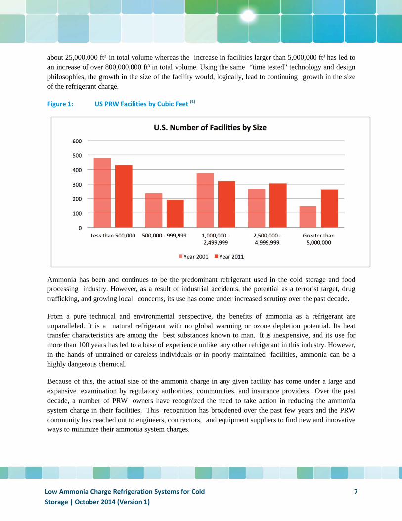
about 25,000,000 ft3 in total volume whereas the increase in facilities larger than 5,000,000 ft3 has led to an increase of over 800,000,000 ft3 in total volume. Using the same “time tested” technology and design philosophies, the growth in the size of the facility would, logically, lead to continuing growth in the size of the refrigerant charge.
Figure 1: US PRW Facilities by Cubic Feet (1)
Ammonia has been and continues to be the predominant refrigerant used in the cold storage and food processing industry. However, as a result of industrial accidents, the potential as a terrorist target, drug trafficking, and growing local concerns, its use has come under increased scrutiny over the past decade.
From a pure technical and environmental perspective, the benefits of ammonia as a refrigerant are unparalleled. It is a natural refrigerant with no global warming or ozone depletion potential. Its heat transfer characteristics are among the best substances known to man. It is inexpensive, and its use for more than 100 years has led to a base of experience unlike any other refrigerant in this industry. However, in the hands of untrained or careless individuals or in poorly maintained facilities, ammonia can be a highly dangerous chemical.
Because of this, the actual size of the ammonia charge in any given facility has come under a large and expansive examination by regulatory authorities, communities, and insurance providers. Over the past decade, a number of PRW owners have recognized the need to take action in reducing the ammonia system charge in their facilities. This recognition has broadened over the past few years and the PRW community has reached out to engineers, contractors, and equipment suppliers to find new and innovative ways to minimize their ammonia system charges.
Low Ammonia Charge Refrigeration Systems for Cold Storage | October 2014 (Version 1)
7
Objectives
The primary objective of this paper is to provide a fundamental and unbiased assessment of the technologies and refrigeration system designs available to the industry leaders which can ultimately lead to a substantially reduced ammonia charge for their cold storage facilities. To meet this objective, a number of diverse but highly viable industrial refrigeration systems will be reviewed in this document. In an effort to perform a relatively comprehensive examination of these systems, several perspectives of the systems and the technology behind them will be addressed:
• The fundamental characteristics of the different systems. • An overview of the estimated equipment, installation, maintenance, and service costs. • The technology’s relative position on the product development curve.
The information contained in this paper which has been provided by the various manufacturers, engineering firms, end users, and refrigeration contractors is assumed to be factually accurate. This document provides a description of system designs currently under scrutiny by the cold storage industry in their effort to minimize ammonia charge without significantly adding to the installed costs, energy costs, or maintenance costs.
The reader will also note that while the various technologies explored here are substantially diverse from each other:
1. The information described in this document does not represent the only options which are currently available.
2. It does not imply that the manufacturers mentioned in this report are the only ones capable of providing the technology, the components, or the systems available in the marketplace.
The pace of the technology evolution has accelerated to a rate that makes it difficult to stay current. Even as this white paper was being written, the author has become aware of additional equipment and manufacturers who are developing products, equipment, and their own system designs to meet the needs of this rapidly changing industry. The purpose of this white paper is simply to provide an overview in a somewhat logical order of new and/or emerging technologies. In most cases, the technology presented in this report has either achieved a respectable degree of market penetration or, as a minimum requirement, has undergone significant beta testing.
Low Ammonia Charge Refrigeration Systems for Cold Storage | October 2014 (Version 1)
8
Reducing Ammonia Charge
It is not an objective of this paper to delve into the history and reasons behind the relatively high ammonia charges seen in today’s cold storage facilities. What has allowed these dramatic improvements to be made in system design is worth noting, however:
• Advanced Controls – providing precise liquid metering for liquid feed and direct expansion systems.
• Advanced Heat Transfer Technology – providing dramatically higher heat transfer coefficients, more consistent and reliable latent heat transfer and optimized heat exchanger designs.
• Advanced Manufacturing Technology – providing higher pressure components, enhanced tube surfaces, small cost- effective screw compressors.
• Advanced auxiliary components – providing expansion valves which “mate” perfectly with the advanced control systems, versatile flow control valves, unique liquid distribution techniques, high pressure pumps.
As the reader will likely conclude in the upcoming pages, the various means of reducing ammonia charge can be categorized into one or more of the following approaches to reducing this charge:
• Eliminating all but the most essential ammonia charge. • Maximizing the heat transfer from the ammonia residing within the system to the air or secondary
fluid. • Substituting other heat transfer fluids for ammonia wherever practical and economically viable. • Rejecting the “more is better” philosophy when it comes to ammonia charge.
All of the system designs under consideration will fall into one of three general categories. Those categories and the drivers behind their development are:
1. Central Systems: Minimize or eliminate unused ammonia charge. 2. Hybrid Systems: Isolate ammonia charge to the machine room and use a second coolant in the
cold rooms in the facility. These systems would still be considered Central Systems. 3. Packaged Systems: Eliminate the central system approach and all of the interconnecting piping
and corresponding ammonia inventory by moving to numerous, smaller self-contained systems
Beyond what is reported in this white paper, it should be apparent that there are other ways to reduce or eliminate ammonia charge. One such way would be to change over to a fluorocarbon refrigerant. This paper will not explore this approach for three primary reasons:
• There are growing regulatory and political forces in play which will continue to stymie and/or kill the use of fluorocarbon refrigerants.
Low Ammonia Charge Refrigeration Systems for Cold Storage | October 2014 (Version 1)
9
• The economics of this approach are not truly viable in part as a result of the first point and in large part because of the inferior thermophysical characteristics of fluorocarbons when compared to ammonia and CO2.
• This is not new or emerging technology.
The Cost of Reducing Ammonia Charge
There’s an old saying that states, “there is no such thing as a free lunch” and it would be a legitimate concern to many that by reducing the refrigerant charge in the systems reviewed in this report some other important variable in the overall operation will suffer. While the primary objective of this document is to examine different ways of reducing ammonia charge, an important additional objective will be to quantify, as best possible, the impact of these newer technologies on:
• Energy efficiency • Installed cost • Maintenance cost
Energy Efficiency – the logical progression of the technology review is to move from systems most similar to a hypothetical typical cold storage refrigeration system to the system most dramatically different. One objective of this document is to report energy consumption for each system on the basis of KW/TR, where:
• KW = power required for all of the motors needed to drive compressors, fans, and pumps • TR = tons of refrigeration
This objective has proven to be one of the more challenging elements of the paper in terms of calculating a credible value for the various systems under review. There are two ways to obtain the values: from the design perspective and from actual operations data. On the design side, the ratio is, essentially, the total kilowatts consumed by the various motors (compressors, fans, pumps) at the design conditions divided by the design loads of the rooms. The problem with this approach is that it is difficult to account for all of the parasitic losses in the system, especially for central systems.
On the operating side, if one had the time, money, and resolve to actually measure amps, voltages, operating hours, and true loads, it can be done but it is a long, arduous, and expensive process to do so. Fortunately, a research project was undertaken by VaCom Technologies on behalf of PG&E a number of years ago on an actual CO2/NH3 Cascade Refrigeration facility with design characteristics quite similar to the baseline system(6). In their overall assessment, VaCom also performed a comprehensive analysis of the expected energy consumption of a comparable pumped recirculated liquid system along with a comparison of the calculated CO2/NH3 system with that of the measured results for the same system. This study represents one of the few undertakings which provide actual performance data with that of theoretical results. Those results will be reported in this paper. Finally, due to the complexity of the topic, part load energy efficiency values will not be taken into account in this paper. It must be emphasized,
Low Ammonia Charge Refrigeration Systems for Cold Storage | October 2014 (Version 1)
10
however, that part load energy consumption is an extremely important variable in that most systems operate in a part load mode most of the year.
Installed Costs – In an effort to present a legitimate degree of relevance, another objective of this paper was to address t h e projected installed refrigeration system costs for the various systems under study. Installed costs will vary significantly by the type of system (central or packaged), local labor costs, and local codes and regulations. The only truly meaningful way to make a fundamentally sound comparison is to collect a large amount of actual cost data from across the country for all of these different systems. Unfortunately, because this paper is focused primarily on new technology, a large pool of data simply doesn’t exist. Fortunately, some cost data was made available and all of the contributors to this document have developed their own cost analyses. For the purpose of reviewing installed costs, the intent of this paper is to focus on the refrigeration system and any structural/building requirements which exist solely for the refrigeration equipment. In the case of a central system, this would include the machine room and, if valve stations are mounted on the roof of the building or in a mezzanine, any additional costs required to do so. For packaged systems, the cost would obviously include the structural housing of the unit itself as well as any additional building support required if the package is to be roof-mounted. In all cases, equipment transportation and rigging are expected to be included in these costs. As noted, it was fortunate that there were contractors, manufacturers, and end users who were willing to share this information in order to provide generalized but realistic values.
Maintenance Cost – As the reader will likely note in the coming pages, most of the systems under review vary significantly in design and construction from each other. As will be reasoned, each system will have its strengths and weaknesses when it comes to maintenance. For example, as the reader will likely note, the packaged systems have a significant increase in the amount of rotating machinery to be maintained at each facility. However, at the same time, these systems almost completely eliminate the most critical mechanical integrity issues and isolate the few that remain to areas easy to service and, open, away from occupied rooms.
Maintenance requirements are a key consideration when determining what type of system works best within the owner’s constraints. At the same time, with little history to lean on, it is extremely difficult to quantify the gains and the losses for this operational expense.
The Basis of Comparison
Given the variety of systems under review, it was a significant challenge to compare these systems on a like basis. This effort was facilitated to some degree by a paper written by Jeff Welch(2) of Welch Engineering Corporation. In his paper, Welch compares a “typical” cold storage facility with that of an Advanced Direct Expansion central system (one of the systems reviewed in this document). Using the same approach as Welch used in his paper in creating this hypothetical system and thanks to the many contributors to this document, a reasonable comparison between systems was made possible.
Low Ammonia Charge Refrigeration Systems for Cold Storage | October 2014 (Version 1)
11
Description of Baseline System
The facility design under consideration is described below:
• Designed as a conventional two-stage pumped recirculated liquid (PRL) system. • Building: 112,000 ft2, 400’ wide by 280’ deep by 30’ high with a 20’ high dock • Loads
o Freezer: 283 tons at -10˚F. o Blast Cells: 6 at 65 tons each, designed to freeze a truck load of product to 0˚F in 24
hours. It is anticipated that blast temperatures would typically fall into the range of -30˚F. o Dock: 80 tons at 45˚F. o The total refrigeration load for the facility is estimated to be 753 tons (9,036,000 BTUH)
In its simplest form, the PRL refrigeration system works in a closed loop cycle as follows:
1. Refrigerant vapor is sent to a compressor which pressurizes it to a much higher pressure and temperature.
2. Once the desired pressure is achieved, heat is rejected from the vapor through a heat exchanger known as a condenser where it eventually becomes all liquid. It is then “stored” in a vessel known as a high pressure receiver.
3. The high pressure liquid is then sent to an expansion device where both the temperature and the pressure of the liquid are reduced and, in the process, some of the liquid is vaporized. This mixture of liquid and vapor is then “stored” in a vessel known as a recirculator. For the system under consideration in this report, a second vessel operating at an even lower temperature receives and stores colder refrigerant.
4. The liquid from the recirculators is then pumped and sent to heat exchangers known as evaporators. Heat from the room passes through the evaporators, into the refrigerant liquid, and vaporizes the liquid. Due to some of the unique characteristics of ammonia, more liquid is sent to the evaporator than is needed to meet the refrigeration load and, as a result, both liquid and vapor pass out of the evaporator and are sent back to the recirculator. The vapor in the recirculator is separated from the liquid and then sent back to the compressor while the liquid drops to the bottom of the recirculator where it can be pumped back to the evaporator to provide additional cooling.
This particular system would best be described as a “soft” optimized pumped recirculated liquid system. For the purposes of this report, it shall be referred to as the Baseline System or PRL. The ammonia charge for this design is estimated at 15,147 pounds or 20.1 pounds of ammonia/ton of refrigeration. As a result of the conservative nature of the industry, a more typical scenario for this type of system would be 17, 314 pounds or 23 pounds of ammonia/ton of refrigeration.
Low Ammonia Charge Refrigeration Systems for Cold Storage | October 2014 (Version 1)
12
What is low charge?
With the baseline system established as the nominal design, all of the other systems will be compared under the same design conditions. A logical question in the reader’s mind may well be, “what constitutes a low ammonia charge system”? In order to be considered as a low ammonia charge system, an arbitrary determination was made that any system considered to have a low ammonia charge would have no more than 50% of the charge of the optimized PRL system.
Going forward, this would mean that all systems under consideration would have to hold no more than 10 pounds of ammonia per ton of refrigeration.
The PRL system under consideration in this white paper is illustrated in Figure 2. The areas and lines of red in this diagram are a qualitative representation of the amount of ammonia in the system. This approach will be carried throughout the paper. The reader should also note that, in the interest of simplicity and focus on the primary elements of each system, a great deal of detail has been intentionally omitted. All of the system drawings in this report show the fundamental components necessary to provide both cooling and freezing. Multiple cooler and freezer coils are shown but do not represent the actual requirements for this system. These drawings are purely for basic illustrative purposes only.
Low Ammonia Charge Refrigeration Systems for Cold Storage | October 2014 (Version 1)
13
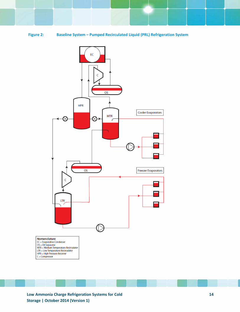
Figure 2: Baseline System – Pumped Recirculated Liquid (PRL) Refrigeration System
Low Ammonia Charge Refrigeration Systems for Cold Storage | October 2014 (Version 1)
14
Theoretical Characteristics of the Baseline System
As noted earlier, the 4 basic characteristics of each system of interest are: ammonia refrigerant charge, energy consumption, installed cost, and maintenance cost. The numbers reported below, represent the best estimates for the system under comparison.
Ammonia Refrigerant Charge
For the purposes of this comparison, the theoretical numbers noted above for the optimized system shall serve as the baseline value. To review, the estimated ammonia charge of this system is 15,147 pounds or 20.1 pounds/ton of refrigeration.
Energy Consumption
As noted previously, energy usage on a true KW/TR basis is a very difficult number to obtain. Every system of this type (the baseline system in this case) will have special circumstances regarding the specifics of its installation which will ultimately influence the final design of the system Some of the circumstances include power cost, demand costs, energy efficiency upgrade incentives, physical layout constraints of the building, etc. For this system, it has been assumed that t h e design has been optimized as far as practical. As noted earlier, VaCom Technologies performed an assessment of a similarly sized cold storage facility on behalf of PG&E in comparing it to an actual CO2/NH3 Cascade Refrigeration System. Their analysis concluded that a system of this nature would consume 2.4 KW/TR at 90˚F condensing temperature. This is a calculated value; however, as will be seen from the other calculated and measured values, it appears to be in line with what one might expect for a system of this nature. It is again emphasized that there are numerous choices made in every design which could cause this value to increase or decrease. It is believed that the value reported here provides a sound frame of reference for comparison to other systems. For the purposes of this paper, an effort will be made to compare systems at a 95F condensing temperature. The additional power consumption due to the increase in condensing temperature is generally modest. For the purposes of this paper, it will be assumed that the power consumption of the baseline unit is 2.5 KW/TR.
Installed Cost
As noted earlier, installed cost can vary significantly from one part of the country to the next. Fortunately, numerous contributors to this document have provided actual numbers. In the case of the baseline system, an advanced Direct Expansion system, similar but not identical to the design requirements of the baseline system, was recently constructed in a major metropolitan region of the Midwest. In designing the system, both a pumped recirculated liquid system and the advanced Direct Expansion system were considered. The design build contractor estimated that the cost of the pumped recirculated liquid system to be $7,148/TR. Other numbers have ranged from $6,000/TR to $8,000/TR. It is believed that a realistic value to use as a reference is $7,000/TR.
Low Ammonia Charge Refrigeration Systems for Cold Storage | October 2014 (Version 1)
15
Maintenance Cost
Maintenance costs are important factors to consider when selecting a system especially as the world begins to evolve towards new technology. While there are going to be both savings associated with the system selection as well as cost increases, there are also going to be factors which will drive these costs up and have little or nothing to do with the system selection. For the purposes of this report, maintenance costs will be viewed in more of a qualitative sense. Because the primary audience is already familiar with the baseline system, the equivalent costs for these other systems will be viewed relative to the baseline system. This is the Baseline Value.
Systems under Consideration
The following systems will be reviewed in this document:
• Advanced Direct Expansion (DX) utilizing electronic expansion valves • CO2/NH3 Cascade • Pumped CO2 Volatile Brine with NH3 Primary • Star AzanechillersTM and AzanefreezersTM
• NXTCOLDTM Packaged Systems
If one were to accept the baseline system as the “conventional” system, there is logic to the order presented above. The Direct Expansion system represents the closest system layout to the conventional system design whereas the NXTCOLDTM system likely represents the most radical departure from the conventional system. All of these systems will be examined in greater detail in the following pages. Figure 3 below is an attempt to provide the reader with a perspective of how these systems compare with respect to each other in terms of ammonia charge and divergence from the traditional system design.
What’s Not Covered in This Review
It is easy to see that it is a complex undertaking to try and compare such a diverse group of system designs. In an effort to simplify and focus on the key elements of the refrigeration system affected by the different technologies, certain aspects of the systems will not be addressed with any substantial detail in this report. Some of the items which won’t be covered include:
• Oil cooling – oil cooling is a necessary element of virtually every open drive compressor used in ammonia refrigeration. There are numerous options available and each packager or system designer will make a choice of oil cooling technique based on the specific circumstances of the design and application. Some of the oil cooling options can add significantly to the charge and will come under greater scrutiny as the priority for charge reduction rises in importance. Additional comments will be provided on this subject in the summary section.
Low Ammonia Charge Refrigeration Systems for Cold Storage | October 2014 (Version 1)
16
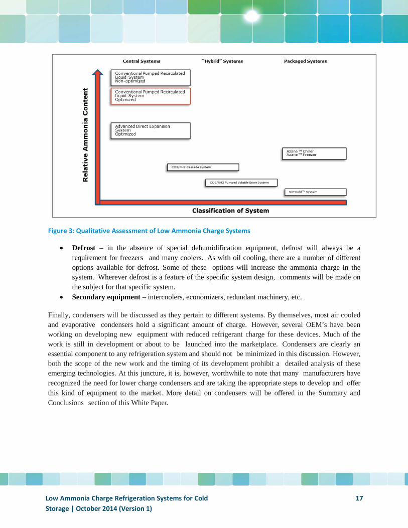
Figure 3: Qualitative Assessment of Low Ammonia Charge Systems
• Defrost – in the absence of special dehumidification equipment, defrost will always be a requirement for freezers and many coolers. As with oil cooling, there are a number of different options available for defrost. Some of these options will increase the ammonia charge in the system. Wherever defrost is a feature of the specific system design, comments will be made on the subject for that specific system.
• Secondary equipment – intercoolers, economizers, redundant machinery, etc.
Finally, condensers will be discussed as they pertain to different systems. By themselves, most air cooled and evaporative condensers hold a significant amount of charge. However, several OEM’s have been working on developing new equipment with reduced refrigerant charge for these devices. Much of the work is still in development or about to be launched into the marketplace. Condensers are clearly an essential component to any refrigeration system and should not be minimized in this discussion. However, both the scope of the new work and the timing of its development prohibit a detailed analysis of these emerging technologies. At this juncture, it is, however, worthwhile to note that many manufacturers have recognized the need for lower charge condensers and are taking the appropriate steps to develop and offer this kind of equipment to the market. More detail on condensers will be offered in the Summary and Conclusions section of this White Paper.
Low Ammonia Charge Refrigeration Systems for Cold Storage | October 2014 (Version 1)
17
Central Systems
Advanced Direct Expansion
General Description
Direct Expansion (also known as Dry Expansion or DX) systems have been in use in refrigeration and air conditioning for decades. Until recently, the use of DX in ammonia based industrial refrigeration systems has been quite limited.
There are a number of technical reasons behind the historical lack of DX systems in industrial refrigeration however; the topic is beyond the scope of this paper. Rather, the focus on DX systems will be its reemergence as a solution to the problem of high ammonia inventories. This revival has come primarily as a result of recent technical advancements. For the purposes of this discussion, the Direct Expansion (DX) system considered in this document will focus on the Colmac Coil approach which incorporates the latest advancements related to:
• Heat transfer • Liquid distribution • Electronic control • System optimization
As noted, the DX system falls into the category of a central system. However, the very nature of a DX system leads to a much more prudent use of ammonia than in the baseline pumped ammonia system. The result is a dramatic reduction in ammonia charge.
A properly designed DX system will:
• Utilize fewer vessels • Utilize fewer pipes • Utilize smaller pipe diameters • Require no pumps
What’s Different?
In comparing a DX system to a pumped system, the reader will likely note more similarities than differences. The key difference between the two systems is that the high pressure liquid in a DX system is fed directly to each evaporator via an expansion device at the evaporator inlet. The heat transfer objective of the evaporator is to vaporize all of the liquid before it leaves the evaporator. While there are many differences in terms of ammonia inventory between the two systems, the 3 main components in a pumped system which hold excess refrigerant are:
• The recirculator vessel • The evaporator
Low Ammonia Charge Refrigeration Systems for Cold Storage | October 2014 (Version 1)
18
• The piping system entering and leaving each evaporator from/to the recirculator vessel
As will be seen, these 3 components are major contributors to the excess ammonia inventory in a pumped system.
Figure 4 illustrates the fundamentals of a Direct Expansion system. The reader should note that a great deal of detail has been purposely left out of the sketch in order to focus on the basic process.
Low Ammonia Charge Refrigeration Systems for Cold Storage | October 2014 (Version 1)
19
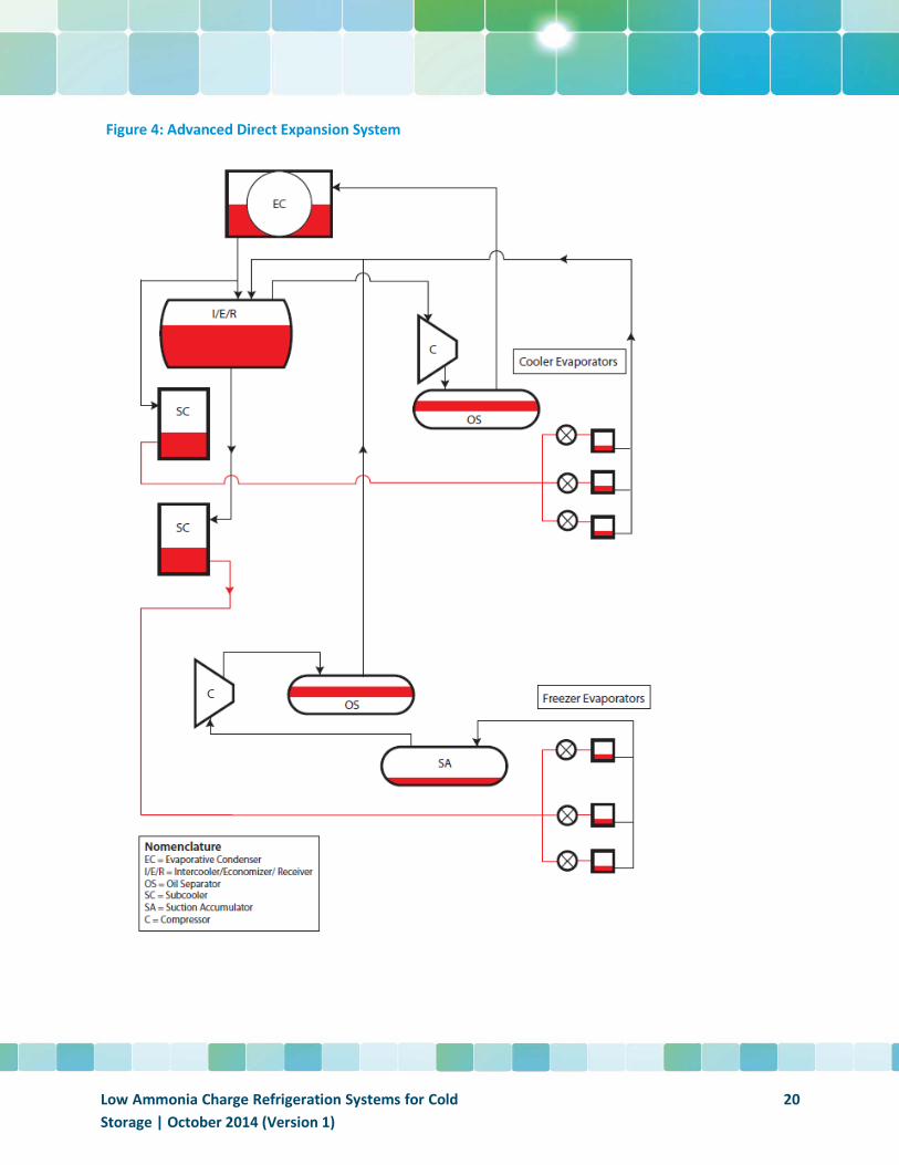
Figure 4: Advanced Direct Expansion System
Low Ammonia Charge Refrigeration Systems for Cold Storage | October 2014 (Version 1)
20
Special Considerations
In order to fully exploit the benefits of an Advanced DX system, there are a number of concerns which must be addressed in order to achieve optimum performance:
• Water removal – while the presence of water is detrimental to evaporator performance in any type of ammonia refrigeration system, it is particularly troublesome in DX systems because it not only raises the boiling point of the ammonia but it also presents a false picture of the actual superheat from a control system perspective. In order to prevent the problems associated with water in the system, it is recommended that a water still/removal device be installed in the system.
• Subcooling – this is an important requirement for DX applications. Subcooling eliminates the formation of unwanted vapor in liquid lines, which can be extremely detrimental to the performance of the expansion device. Subcooling the liquid to a sufficient extent will normally eliminate this possibility and ensure that the expansion device and the coil perform as predicted.
• Electronic Expansion Devices – there are two basic types of electronic expansion valves suitable for ammonia applications: pulse width modulating valves (PWM) and motorized valves (often referred to as EEV). For coil applications, either type is suitable, although the PWM valve has some limitations with respect to minimum required pressure differential. What is important to evaluate before selecting any expansion valve is its ability to respond as fast as the controller which is directing its action requires.
• Controls and Variable Frequency Drives – The use of advanced control algorithms is essential to ensuring that liquid is metered to the coil circuits in such a way that the evaporator performance is optimized. At the same time, the control system must be able to provide a high level of assurance that little or no refrigerant liquid is carried over to the suction accumulator vessel. In order for those controls to perform reliably, steps should be taken to avoid sudden, dramatic changes in suction pressure and/or discharge pressure. The most effective means of doing this is to employ variable frequency drives on condenser fans, and compressors as a means of controlling the rate of change in these devices.
Ammonia Refrigerant Charge
In his paper, Jeff Welch estimated the charge of a baseline pumped system and an equivalent DX system. The DX system had an ammonia charge of 6053 pounds. On a per ton basis, this translates to roughly 8 lbs. of ammonia/ton of refrigeration or about 40% of the charge of an optimized pumped system. A new, all DX facility was recently commissioned in the Midwest USA. The design of the facility was similar to the hypothetical system and resulted in an ammonia charge of approximately 7.5 pounds per ton of refrigeration. The author has visited the new facility and is aware of the reasons for the difference in charge. For the purposes of this generalized discussion, the charge for the DX system will be set at 7.5 pounds/TR.
Low Ammonia Charge Refrigeration Systems for Cold Storage | October 2014 (Version 1)
21
Energy Consumption
There isn’t a lot of data available to compare the energy consumption of a DX system with that of a pumped system. In a very general sense, however, the DX system should be very similar to a pumped system. Compressor suction pressure will be lower due to the formation of superheat in the evaporator; however, with today’s advanced controls, superheat can be significantly decreased and have only a small impact on system efficiency. Discharge pressures are similar and, with electronic expansion valves, discharge pressures can be reduced when the opportunity arises. Fan horsepower for the condensers and evaporators should also be very similar between the two systems. There is a slight energy savings for the DX system in not having any recirculator pumps and, while there may be a small penalty for subcooling, it is likely insignificant. Therefore, the conclusion for this document is that there are no significant differences in energy consumption when comparing to the baseline system – with one exception. As a result of the significantly reduced liquid
charge in the evaporators and top feed evaporators, pump out time for hot gas defrost should be dramatically reduced over that of a bottom fed pumped recirculated liquid system. This should have the effect of saving energy in two ways:
• Shorter defrost cycles • Reduced heat input to the room during defrost
In his report, “DX Ammonia Piping Handbook” (3), Bruce Nelson estimates that the savings on the defrost cycle alone can range from $12,000 to $26,000 per 100 tons per year over that of a bottom feed pumped system. At this point, there is little data to support a significant deviation from the value reported for the baseline system. To be conservative, the energy usage for the DX system will be estimated at 2.5 KW/TR.
Installed Cost
The reader will recall the earlier discussion of the baseline system and the comparison of an actual DX project with that of the equivalent pumped system. In this case, the actual cost of the DX system came in at $6,920 per ton of refrigeration or, about 97% of the cost of the pumped system. As these systems become more popular and additional technology arrives in the market, it is likely that the savings will become even greater. For the purposes of this paper, the estimated installed cost of a DX system will be estimated at 97% of the baseline system or, $6,800/TR.
Maintenance Cost
There is no significant difference in maintenance costs for the DX system over that of the pumped recirculated liquid system. On the plus side of cost, there are oil stills and anhydrators which must be maintained; however, it is anticipated that there will be far less oil to drain throughout the system (as less oil is carried to the evaporators as a result of the oil stills) and no refrigerant pumps to maintain. Therefore, for the purpose of this analysis, it is assumed that maintenance cost will be the same as for the baseline system. Maintenance Cost Vs. Baseline = Even.
Low Ammonia Charge Refrigeration Systems for Cold Storage | October 2014 (Version 1)
22
Hybrid Systems
CO2/NH3 Cascade
General Description
While the Direct Expansion system is one of the oldest alternatives to pumped recirculated liquid systems in industrial refrigeration, CO2 systems have roots in industrial refrigeration as far back as the 19th century. Until recently, the thermophysical characteristics of CO2 have made it difficult to utilize CO2 as a working refrigerant in industrial refrigeration systems in a practical and cost-effective manner. However, significant advances in materials, manufacturing, equipment designs, and controls have made it a highly viable alternative to many of the more common refrigerants and heat transfer fluids and at least one major cold storage company is using CO2/NH3 systems extensively throughout its organization. There are a several variations in using CO2 refrigeration. Two such systems shall be explored in this paper. In this section, the focus will be on compressed CO2 for the room side with ammonia serving as the initial heat sink (condenser) for the CO2 process.
The type of system described as CO2/NH3 Cascade isolates the ammonia refrigeration part of the system to the machine room. As with all refrigerants, the higher the temperature of the refrigerant, the higher the operating pressure. In order to limit the extremely high pressures necessary for an all- CO2 system, the ammonia part of the system provides the initial condensing for the CO2 system and thereby limits the pressure which would exist if CO2 were to be condensed as in a typical refrigeration cycle (95˚F Condensing Temperature, typically). The evaporator for the ammonia system is also t h e condenser for the CO2 system. This type of heat exchanger is referred to as a cascade heat exchanger and can be constructed in a number of different ways:
• Shell and tube • Welded plate • Shell and plate
The choice of style will have a direct impact on the refrigerant charge of the system with shell and tube requiring the most refrigerant and welded plate requiring the least refrigerant.
There are several different approaches taken in achieving the desired temperature levels of the coolers and the freezers. The methodology for this particular configuration has been as follows:
1. Cool the CO2 down to the temperatures required by the coolers through the cascade heat exchanger and send to the CO2 recirculator vessel.
2. Move the cool liquid to the coolers and freezers a. Pump some of the condensed CO2 to the cooler coils from the cascade heat exchanger.
Unlike ammonia, recirculation rates are maintained much closer to 1:1 allowing almost all of the CO2 to be evaporated. This has the added benefit of reducing the size of the evaporator and the horsepower of the pump.
Low Ammonia Charge Refrigeration Systems for Cold Storage | October 2014 (Version 1)
23
b. Supply additional liquid from the CO2 recirculator to the freezer coils. Each coil is equipped with an electronic expansion valve to lower the temperature and pressure of the CO2 to the desired temperature
3. Return the gas/liquid mixture from the cooler coils and the freezer coils to the CO2 recirculator. 4. The vapor collected in the recirculator is then sent back to the CO2 compressor, compressed and
sent to the cascade heat exchanger to be condensed while the liquid is circulated back to the coolers and freezers.
The system is relatively simple and doesn’t require much more equipment than a 2 stage pumped recirculated system would. As will be noted below, due to some of the thermophysical properties of CO2, there can be some significant savings on the equipment for this type of system. Additional advantages offered by CO2 as a refrigerant arise from its high heat transfer coefficient at very low temperatures and favorable vapor to liquid volumetric ratios. This leads to:
• More efficient cascade heat exchanger (reduced energy consumption due to a smaller temperature difference requirement)
• Smaller evaporators • Lower recirculation rates • Smaller pumps • Reduced pumping power demands
As seen in Figure 5, all of the ammonia is confined to equipment residing in the machine room. The reader should note that a great deal of detail has been purposely left out of the sketch in order to focus on the basic process.
Low Ammonia Charge Refrigeration Systems for Cold Storage | October 2014 (Version 1)
24
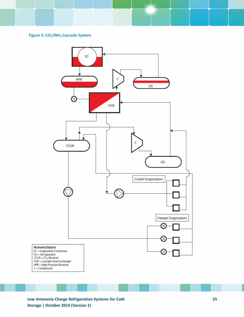
Figure 5: CO2/NH3 Cascade System
Low Ammonia Charge Refrigeration Systems for Cold Storage | October 2014 (Version 1)
25
There are a number of special considerations when using CO2 as a refrigerant:
• It is important to consider what the pressure could, potentially, rise to during “stand still”. Stand still is the point at which power has been disconnected from the system (intentionally or unintentionally) and pressures can begin to build up to dangerous levels as a result of the heat transferred from the ambient environment. The simplest solution to the problem is to install a small condensing unit driven off of a generator to condense any vaporized CO2 within the system; thereby preventing an excessive pressure rise. Of course, the system will have safety relief valves installed as a preventive measure; however, it is always desirable to keep the CO2 contained within the system.
• This CO2 system is referred to as a subcritical system. By that it is implied that operation of the system is limited to within the range between the critical point (88°F) and the triple point (-70°F). In general, this allows the system to operate between 83 psi/-67°F and 507 psi/32°F (5). Using CO2 hot gas to defrost the evaporators will increase the upper limit of the pressure requirement to about 652 psi. A properly designed system will have no problem in maintaining the correct operating conditions; however, the user must be aware of conditions which can arise during periods of standstill noted above.
• Water can have an extremely negative impact on CO2 evaporators and, under certain circumstances, on other system components. Therefore, the system must be kept dry. The problems associated with water in CO2 systems is directly related to its low solubility limits. In essence, this means that components can be negatively impacted by
• Water once the solubility limit has been reached and, especially, when temperatures are below freezing. Carbonic acid formation can also occur as a result of water in the system. This acid can be highly detrimental to carbon steel components in the system. The solution to the problem is to incorporate and maintain filter/driers in the system design. Filter/driers should be installed in liquid lines prior to evaporators.
• Oil must be kept in that part of the system where oil is required (the compressor) and not allowed to migrate to the low temperature evaporators. The use of an oil “still” or something equivalent is strongly recommended in order to keep the oil in the region of the compressor and not in the low temperature parts of the system.
• As noted in the second point, the use of hot gas defrost can increase the system design pressures by as much as 145 psi and, will also add to the total ammonia refrigerant charge. Hot gas defrost is typically provided through a compressor dedicated just for that purpose.
• Although CO2 is a non-toxic and non-flammable refrigerant, it is heavier than air and, therefore, sinks to the ground or floor level. This can create dangerous situations in confined spaces by resulting in non-breathable air. Leak detection and emergency ventilation systems are essential in any ammonia design and, although not seemingly as important, are just as essential in CO2
systems. • Understanding the interaction between CO2 and oil is an essential ingredient in ensuring
successful operation. There are two potential types of oils for compressed CO2 systems: Polyalphaolefin (PAO) oil and Polyolester (POE) oil. In general, both oils have their positive and negative attributes when it comes to their interaction with CO2. For the most part, the only real
Low Ammonia Charge Refrigeration Systems for Cold Storage | October 2014 (Version 1)
26
negative component of the POE oil is its affinity to water. As a result, in order to ensure the long term stability of the POE oil, it is essential that the system remain as water-free as possible. As noted, filter driers will accomplish this objective.
Ammonia Refrigerant Charge
From Figure 5, the reader will quickly note that all of the ammonia charge for this system is isolated to the machine room. As previously pointed out, the ultimate ammonia charge will depend on several factors:
• the type of cascade heat exchanger • type of condenser • The size and amount of piping connecting the CO2 and NH3 systems.
While it has been estimated that the ammonia charge in a system like this can be, potentially, reduced to as low as 10% of the ammonia charge in a typical pumped recirculated liquid system, the actual numbers are likely to much higher than this theoretical value. Fortunately, data exists on existing CO2/NH3
Cascade systems which provide actual experiences. US Cold Storage currently has 7 - CO2/NH3 Cascade facilities in operation and 2 more under construction. They have been kind enough to share their experiences with the cold storage community. Information provided in this report does not represent any individual USCS facility but rather represents data on an aggregate basis. With respect to ammonia charge, the typical ammonia charge in the USCS facilities is approximately 8 lbs./ton of refrigeration. The reader will note on the summary page that the theoretical value for this type of system is about 25% lower than those reported by USCS. There are a number of possible explanations for the difference between the USCS facilities and the theoretical values. A broad generalization would suggest a charge of between 4 and 6 lbs./TR. It is clear that while 4 lbs./TR is achievable, it may not be the most practical objective. More discussion of the factors that weigh into the final number will be found in the Summary section of the report. For the purposes of this report, the charge will be conservatively estimated at 6 pounds/TR.
Energy Consumption
As noted in the introductory comments, energy consumption is a fairly easy number to track at the plant level. However, calculating ratios such as KW/Ton of Refrigeration is much more challenging for a central system. The main difficulty in developing these numbers is in determining the actual loads which correspond to the measured kilowatt-hours. All reported figures in this document have to be viewed with the understanding that actual loads are almost always going to be less than design loads. USCS has estimated their average power consumption to lie somewhere between 1.8 and 2.0 KW/Ton of refrigeration. This value, however, is based on design loads and measured kilowatt hours thus, it is clear that the actual value for KW/TR is going to be a higher value. In general, USCS refrigeration loads are fairly heavy on blast freezing. CO2 is a particularly energy efficient refrigerant at temperatures below -30˚F and, if a large percentage of the total plant load falls into this category, it should not be surprising to see very attractive energy usage figures. In addition, since these are aggregate numbers for 7 different facilities, it is also likely that the actual condensing temperatures are well below 95˚F. This would also
Low Ammonia Charge Refrigeration Systems for Cold Storage | October 2014 (Version 1)
27
have the effect of lowering the KW/TR ratio. The general conclusion here is that the true ratios are probably higher than those reported by USCS, but the values do project numbers which fall within the broad range that would be anticipated for this type of system. Based on the work done by VaCom (6), there is strong evidence t h a t facilities with blast freezers exhibit significant improvements in energy consumption when using CO2/NH3 cascade systems. The cascade system exploits the best efficiencies of NH3 and CO2 compressors: NH3 compressors have higher efficiencies at higher temperatures; CO2
compressors have higher efficiencies at lower temperatures. The optimum temperatures for this efficiency improvement are typically lower than the -30˚F target reported earlier. CO2 refrigeration has also been a topic of much controversy in the industrial refrigeration arena. Theoretical simulations typically suggest energy consumption numbers to be higher than that of a well performing, equivalent PRL system. Some user experiences including that of the VaCom study suggest otherwise. The reader is referred to a very comprehensive study undertaken by the Industrial Refrigeration Consortium comparing two stage ammonia PRL systems with CO2/NH3 Cascade systems(8).
The value for the system in the VaCom study was equal to: 2.3KW/TR. Assuming a small decrease in efficiency at a 95˚F condensing temperature, the value assumed for this system will be set at 2.4 KW/TR. Taking into account the amount of theoretical work that has been undertaken in order to compare the two systems, it is probably prudent to use a value not less than that of a PRL system. For the purposes of this white paper and, until more actual data is compiled, the value will be set at 2.5 KW/TR.
Installed Cost
One of the highly beneficial characteristics of CO2 when compared to NH3 is the reduced pipe diameter for CO2 vapor compared to NH3 vapor. (Liquid lines for CO2 are typically larger than those for NH3 but still fall into the small diameter piping category.) Because vapor lines typically represent some of the larger diameter piping and longer runs of piping in any facility, the installed costs of vapor carrying pipe can be significant. Smaller diameters translate to savings in:
• Piping (if the same materials are used for both systems) • Transportation • Welding (if the same weld procedures are used for both systems) • Painting (if applicable) • Insulation
It should not be surprising to find that a CO2/NH3 Cascade system can be more cost effective from an installation perspective than a pumped recirculated liquid system; however, there are many “ifs” in the above list. In this case, USCS has determined that the average installed cost of their CO2/NH3 Cascade systems was at the low end of the scale for all installed systems. This might be attributed to economies of scale as USCS facilities are usually quite large or perhaps favorable locations with respect to building costs or other factors. Refrigeration contractors, on the other hand, have provided a somewhat different perspective. While the cost of this type of system is not significantly higher than the baseline system, 3 very large contractors who have both quoted and built CO2/NH3 facilities all stated that the CO2/NH3
Cascade system carried a slight premium in cost over that of the baseline system. For the purposes of this
Low Ammonia Charge Refrigeration Systems for Cold Storage | October 2014 (Version 1)
28
report, it will be assumed that there is a 5% premium in installed cost over the baseline system or $7,400/TR.
Maintenance Cost
Other than the fact that half of this system uses CO2 as the refrigerant, there isn’t a great deal of difference between the CO2/NH3 Cascade system and a conventional pumped recirculated liquid system. Of course, as noted under Special Considerations, CO2 has a few challenges which must be carefully controlled. The two areas of special importance in the CO2 system are the filter driers and the oil management system. A facility with a sound maintenance plan and a reliable maintenance staff should find no problems in meeting the special requirements of maintaining filter driers and the oil and water stills with little increase in maintenance cost. The conclusion here is that while maintenance costs may be slightly higher than for a pumped recirculated liquid system, they will have a minimal impact.
Maintenance Cost vs. Baseline = Even
CO2/NH3 with Pumped Volatile Brine (PVB)
General Description
The CO2/NH3 system with pumped volatile brine has many similarities to the CO2/NH3 Cascade System. In this system, however, there is no primary CO2 compressor. It is possible that there may be a small CO2
compressor for the hot gas defrost system but there are also other options which allow for defrost without adding a compressor for that purpose. To many, this system would be described as a chiller system; however, what distinguishes this system most from what is typically thought of in terms of a chiller is the word “volatile”. Most chiller systems use water or some formulation of glycol/water and the cooling coil is no longer an evaporator but rather just a sensible heat exchanger. This has an enormous impact, not only, on the amount of heat transfer fluid that is required to meet the cooling load but also on pump size, pumping power, piping size, and the heat exchange size. Compared to a traditional chiller system, the CO2/NH3 pumped volatile brine system has higher energy efficiency and, usually a lower installed cost. Actual data for industrial refrigeration systems is still scarce; however, in similar systems for commercial refrigeration, it has been found that the pumping power required to circulate CO2 as a volatile secondary refrigerant represents about 5% of the power that would be required to circulate a non-volatile secondary refrigerant such as water or glycol(7).
As noted in the previous section on CO2/NH3 Cascade systems and in this section under special considerations, CO2 systems typically operate between 83 psi and 507 psi. What this means is that the piping is always under pressure and the ability for water or air to be drawn into the system is virtually non-existent. This is not to say that water and air along with other contaminants can’t find their way into the system but the likelihood is greatly diminished.
The system description shown in Figure 6 describes a system in which the liquid CO2 is cooled down to a temperature low enough to satisfy the cooling loads in the freezers. The liquid is cooled to the required temperature in the cascade heat exchanger and then stored in the CO2 recirculator vessel. This same
Low Ammonia Charge Refrigeration Systems for Cold Storage | October 2014 (Version 1)
29
refrigerant is then used to satisfy the cooling loads of the coolers. The key component in meeting the cooler requirements is the pulse width modulating valve. Normally used for DX systems, the pulse width modulating valve is used, in this system, simply as a metering device to supply enough refrigerant to meet the load requirements of the coolers. There is no intention of evaporating all of the refrigerant as in a DX evaporator but rather simply to satisfy the room temperature setting.
The approach taken for this particular design was chosen because of the high ratio of freezer load to that of cooler load. If the ratio was reversed, it is likely that a different design philosophy would have been adopted. Since there is no compressor and no suction accumulator, no effort is made to ensure that liquid isn’t carried out of the evaporators. The main driver behind this approach is the temperature at which coolers typically operate. If the cooler is set at, say 55˚F, and the evaporator has been designed for a 10˚F temperature difference, the CO2 would be operating at nearly 600 psig.
While this is not an unmanageable number, it does push the limit on some of the equipment requirements (especially the pump).
Low Ammonia Charge Refrigeration Systems for Cold Storage | October 2014 (Version 1)
30
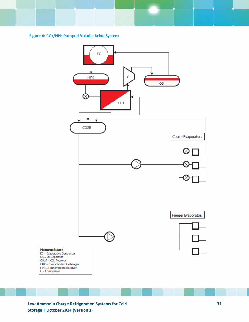
Figure 6: CO2/NH3 Pumped Volatile Brine System
Low Ammonia Charge Refrigeration Systems for Cold Storage | October 2014 (Version 1)
31
Special Considerations
The special considerations for the CO2/NH3 with Pumped Volatile Brine are nearly the same as that for the CO2/NH3 Cascade system:
• It is important to consider what the pressure can rise to during “stand still”. Stand still is the point at which power has been disconnected from the system (intentionally or unintentionally) and pressures can begin to build up to dangerous levels as a result of the heat transferred from the ambient environment. The simplest solution to the problem is to install a small condensing unit driven off of a generator to condense any vaporized CO2 which is causing the pressure to rise. Of course, the system will have safety relief valves installed as preventive measure; however, it is always desirable to keep the CO2 contained within the system.
• This CO2 system is called a subcritical system. By that it is implied that operation of the system is limited to within the range between the critical point and the triple point. In general, this allows the system to operate between
• 83 psi/-67˚F and 507 psi/32˚F. Although it is unlikely that defrost will be done using CO2 hot gas to defrost the evaporators, doing so will increase the upper limit of pressure requirements to about 652 psi. A properly designed system will have no problem in maintaining the correct operating conditions; however, the user must be aware of conditions which can arise during periods of standstill noted above.
• Water can have an extremely negative impact on CO2 evaporators and, therefore, the system must be kept dry. The problems associated with water in CO2 systems is directly related to the low solubility limits. In essence, this means that components can be negatively impacted by water once the solubility limit has been reached and, especially, when temperatures are below freezing. The solution to the problem is to incorporate and maintain filter/driers in the system design.
• Oil is not required for the CO2/NH3 Pumped Volatile Brine system. • As noted in the second point, the use of hot gas defrost can increase the system design pressures
by as much as 145 psi and, will also add to the total ammonia refrigerant charge. Hot gas defrost is typically provided through a compressor dedicated just for that purpose.
• Although CO2 is a non-toxic and non-flammable refrigerant, it is heavier than air and, therefore, sinks to the ground or floor level. This can create dangerous situations in confined spaces by resulting in non-breathable air. Leak detection and emergency ventilation systems are essential in the design.
Ammonia Refrigerant Charge
Because the system under consideration requires blast freezing, the ammonia temperature available to condense CO2 liquid as low as -50˚F, would have to be on the order of -60˚F. For all practical purposes, this would require a two stage refrigeration system for the ammonia. At first glance, it might appear that the charge will be quite high due to the two compressors, intercooler (optional), and a heat exchanger large enough to satisfy the entire load of the cold storage facility. The reader must keep in mind, however, that there is minimal piping, no evaporators (other than the cascade heat exchanger), a condenser, and only a modestly sized receiver. There isn’t a lot of good information available at the time
Low Ammonia Charge Refrigeration Systems for Cold Storage | October 2014 (Version 1)
32
of this writing to determine the actual charge in a system like this; however, in an effort to stay consistent with the analysis from Welch’s paper, a value has been calculated using the basic numbers for the DX system without all of the piping and vessels (see Figure 11 in Summary section.). Although it is believed that the actual ammonia refrigerant charge could be as low as 2.5 lbs./TR, there is little data available to support this theoretical value at this point. Instead the systems ammonia charge will be assumed to be the same as that of the CO2/NH3 cascade system or, 6 lbs./TR.
Energy Consumption
Energy Characteristics – this section started out with a cursory comparison to a chiller system. As noted previously, the characteristics of CO2 and the fact that the heat exchangers are truly evaporators contribute to a sound energy efficiency image. There are other aspects of the system equipment which, when combined with the characteristics of CO2, continue to present an attractive energy picture. One of the main features of the refrigerant is its high heat transfer coefficient.
This feature leads to smaller temperature differences in both the evaporators as well as the cascade heat exchanger. Along with the fact that the pumping power requirements are also low for CO2, the end result is that the system efficiency is close to that of a pumped recirculated liquid system.
As noted in the beginning of this paper, there are many factors which contribute to the overall energy consumption of each system. The use of CO2 volatile brine is not new but has had limited deployment in cold storage applications. For the purposes of this white paper, it will be assumed that the CO2/NH3
Pumped Volatile Brine system is only slightly more energy intensive than the baseline system. This assumption is based on a generalized view of the “energy consumers” in this system and how they would be expected to compare with an equivalently sized baseline system. The value which will be used in this report is 2.5 KW/TR.
Installed Cost
The installed cost of the system will likely be very similar or just slightly more expensive than that of the CO2/NH3 Cascade system. The ammonia refrigeration system will be larger and more costly but there are no CO2 compressors in this system unless hot gas is the desired route for defrost. The cascade heat exchanger will be larger for the CO2/NH3 Pumped Volatile Brine system but there will be no need for an oil still. With this in mind, a conservative estimate for the cost of the system is set at $7400/TR.
Maintenance Cost
As with all of the systems under consideration in this report, maintenance cost as compared to the based pumped ammonia system has some beneficial aspects and a few items which will require more attention. On the plus side, since all of the ammonia is confined to the machine room, oil sumps are very manageable and oil draining is limited to a significantly reduced number of vessels. Since the volatile brine system has no requirements for oil, there is no oil draining requirement.
Low Ammonia Charge Refrigeration Systems for Cold Storage | October 2014 (Version 1)
33
On the additional cost side of the equation, filter driers must be monitored and maintained on a routine basis. As noted under Special Considerations, a backup condensing unit is highly recommended for periods of “stand still”. This system must also be maintained on a routine basis to ensure that it is in good working order when and if the time is needed for its use.
The overall conclusion regarding maintenance costs is that any increase in cost over that of a conventional pumped recirculated liquid system will be minimal.
Maintenance Cost Vs. Baseline = Even
Packaged Systems
The AzanechillerTM and AzanefreezerTM
General Description
The Azane product line is produced by a subsidiary of Star Refrigeration out of the UK. As a packaged system, there are a number of basic advantages when it comes to reducing ammonia refrigerant charge including:
• Elimination of the machine room • Elimination of the large scale vessels required for holding ammonia charge • Minimization of distribution piping throughout the facility
The AzanechillerTM, as seen in Figure 7 also takes on a key feature of a hybrid system in that it uses a chiller to provide refrigeration to the coolers and docks. The overall impact is a dramatically reduced ammonia charge and no ammonia is present in the rooms being cooled by the chiller. However, there is a negative impact on system efficiency as a result of the extra heat exchanger (the chiller) and the subsequent inefficiencies of pumping glycol to sensible heat exchangers rather than true evaporators.
The system designs do, however, incorporate a number of features which provide advantages in installation cost and timing. Some of the standard features aimed at improving energy efficiency include:
• Floating head pressure control • Floating suction pressure control • Variable frequency drives for condenser fans • High efficiency screw compressors
This product also introduces the concept of critically charged systems. A critically charged system is one in which the refrigerant is always undergoing change: expansion, compression, heat transfer. That is, there is no excess refrigerant residing in the system waiting for the moment when more refrigerant is needed in some part of the process. This is not a new concept for smaller residential and commercial air
Low Ammonia Charge Refrigeration Systems for Cold Storage | October 2014 (Version 1)
34
conditioning and refrigeration systems; however, it represents a significant deviation from the typical pumped recirculated liquid industrial refrigeration system.
The AzanechillerTM utilizes ammonia as the primary refrigerant in “chilling” a secondary heat transfer fluid for the medium temperature rooms of a cold storage facility. This secondary heat transfer fluid is usually glycol. As seen in Figure 7, the glycol is cooled by use of a plate exchanger located in the package and then distributed to the docks and coolers as required. The condensers may be air cooled or water cooled. Azane has developed 7 different models of air cooled units capable of providing between and 300 tons of refrigeration depending on model. A number of advanced features incorporated into the design include variable speed fans for the air cooled condensers, high effectiveness condenser coils, fully automatic oil return, and a fully integrated PLC control system.
The AzanefreezerTM is an industrial condensing unit which utilizes ammonia as the only refrigerant for the entire system as seen in Figure 7. As with the AzanechillerTM, refrigerant charge is minimized as a result of the packaged approach along with a number of advanced design features including high effectiveness evaporator and condenser coils, an ultra- low charge low pressure receiver, and highly efficient defrost methodology. The defrost methodology for the AzanefreezerTM is worth noting in that the system really acts like a heat pump. During the defrost part of the cycle, the evaporators act as condensers in giving up heat to melt the ice on the evaporators and the condenser acts as an evaporator in re-vaporizing the defrost condensate. Star believes that the net result is a defrost cycle which is faster and more energy efficient than a traditional hot gas defrost cycle. The key component in the reverse cycle defrost is a 4 port valve which is located within the condensing unit. This valve was developed in the 1980’s specifically for this application and has proved to be very reliable in operation. The 4 port valve is the only valve required for the reverse cycle system which results in a greatly simplified system, with far fewer valves than a traditional hot gas defrost system.
The AzanefreezerTM uses a unique low pressure receiver (LPR) system design, which allows all of the control valves to be located within the condensing unit. This eliminates the need for valve stations at the evaporators, greatly reducing the number of potential leak paths in the system and has the added benefits of greater efficiency and simplified maintenance. Star’s low pressure receivers have been installed in numerous European facilities for over 20 years. One additional feature of the system which helps to greatly minimize charge is the low overfeed rate of the evaporators. The combination of the low pressure receiver (LPR) and advanced aluminum evaporators has led to a highly efficient system with minimum refrigerant charge, no pump, and no valves or mechanical joints in the refrigerated room.
At the time of this writing, there are 5 air cooled models being offered ranging in capacity from 25 tons of refrigeration to 71 tons when rated at -10˚F. Azane anticipates the release of higher capacity units and units capable of blast freezing in the near future.
Figure 7 illustrates the basic concept of how the two Azane units would be installed in a typical cold storage facility. The reader should note that a great deal of detail has been purposely left out of the sketch in order to focus on the basic process.
Low Ammonia Charge Refrigeration Systems for Cold Storage | October 2014 (Version 1)
35
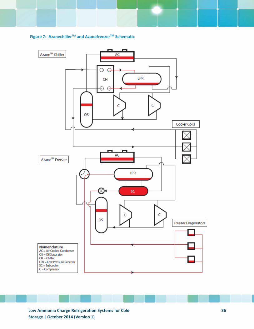
Figure 7: AzanechillerTM and AzanefreezerTM Schematic
Low Ammonia Charge Refrigeration Systems for Cold Storage | October 2014 (Version 1)
36
Special Considerations
The Azane units can be ground-mounted or roof-mounted. The advantage of roof mounting, in theory, is to be close to the evaporators and thus reduce the amount of charge in the piping system to those evaporators. However, other considerations must be given to the structural and seismic factors of mounting a fairly heavy package on the roof. Weights of the units range from just over 100 lbs./ft2 to 200 lbs./ft2.
Ammonia Refrigerant Charge
There are a number of factors which will enter into actual refrigerant charge of these units: type of condenser, location of packaged system in relation to the evaporator location and, of course, the size of the package in relation to the actual load requirements. The total number of units required for the target facility is:
• Blast Freezers – Qty. 9 GP5 • Freezers – Qty. 4 AF45 • Docks – Qty. 1 AA120
The total ammonia refrigerant charge equals 3,245 pounds or approximately 4.3 lbs/TR.
Energy Consumption
As with all systems under consideration, energy usage must be a major factor in making any type of decision regarding the type of refrigeration system to be installed. The total energy consumption for the Azane units will depend on the options chosen. The typical range of energy usage for air cooled condensers is expected to be as follows:
• Azanefreezer: 2.5 to 2.7 KW/TR at -10˚F • Azanechiller: 1.15 to 1.25 KW/TR for a 45˚F room • Glacier: 2.7 KW/TR for -30˚F blast freezing
In an effort to view this conservatively, looking at the higher end of the range, the total for the system under consideration would be 1817 KW for the freezers and 100 KW for the chiller. Not shown in the diagram is a separate system from Star referred to as the Glacier Package. The Glacier Package would utilize an evaporative condenser rather than the air cooled condenser found on the AzanechillerTM and AzanefreezerTM. This package would be used for the blast freezing portion of the system and has been demonstrated to be highly energy efficient. While the air cooled condensers are rated for a condensing temperature of 110˚F, the energy ratings are based on the typical 95˚F condensing temperature. The overall projected electric power figure is quite respectable. The combination of these elements yields an overall projected electric power cost of KW/TR.
Low Ammonia Charge Refrigeration Systems for Cold Storage | October 2014 (Version 1)
37
Installed Cost
As noted previously, installed cost can vary dramatically as a result of a variety of factors. In the case of packaged systems, the cost will, typically, vary inversely with the size of the system. Smaller systems (under 200 TR) will typically show an installed cost savings of 10% to 20% of a central system (Pumped Recirculated Liquid). Average sized systems (200 to 500 TR) will cost about the same as a central plant and in this case because of the large percentage of load going to the blast freezers, Star/Azane estimates the cost to be equivalent to that of a PRL system. Large systems over 500 TR with typical coolers and higher temperature freezers are expected to require a premium of about 10% over that of a central system.
For the system under consideration, however, the estimated installed cost per ton of refrigeration is: $7,200/TR.
Maintenance Cost
The design of the Azanechiller and Azanefreezer is such that most components are housed inside a robust package and are easily accessible for any unexpected or routine maintenance. The history of these units has demonstrated a relatively trouble-free system and Star’s own experience when quoting service packages for both types of systems has always shown a savings for the packaged approach. Some of the features of the units are:
• Automatic oil return • Telstar PLC controller – monitors various key parameters in the system and issues maintenance
alerts to warn of any developing problems • Each unit is equipped with two compressors and, under most circumstances, only one is running
at a time. • Air cooled condensers – eliminates need for water treatment
All other maintenance as listed in Azane’s Operating and Maintenance manual are similar to what any facility should expect to be doing on its pumped recirculated liquid system.
Maintenance Cost Vs. Baseline = Less
The NXTCOLDTM System
General Description
The NXTCOLDTM System represents a dramatic advance in the use of refrigerant by utilizing a number of proprietary technologies in both liquid feed to the evaporator and a unique liquid feed control algorithm. This system represents the lowest ammonia charge of all systems under review in this document. The NXTCOLDTM system was first conceived 6 years ago. The first test cell went into operation in 2012 and since then a number of beta sites have been installed. In 2013 the first NXTCOLDTM complete refrigeration system penthouse unit went into operation in place of a flooded ammonia system which held approximately 500 pounds of ammonia charge. The NXTCOLDTM penthouse unit runs with approximately
Low Ammonia Charge Refrigeration Systems for Cold Storage | October 2014 (Version 1)
38
5 pounds of ammonia charge. That charge can be increased by 40% as a safety factor if desired which brings the total charge up to 7 pounds (approximately .5 pounds per ton).
While there are a number of variations available for both new construction as well as retrofit, this paper will only review the packaged systems (the above-referenced penthouse style system). Each packaged system consists of one compressor, one evaporator, and one liquid feed valve system and control system. The systems can be applied to coolers, docks, freezers, and blast freezers. As with all packaged systems, multiple stand-alone systems of varying capacity and temperature requirements will be installed in a facility depending on the refrigeration requirements.
There are different options available for condensers: air cooled, water cooled, central cooling tower, and advanced air cooled heat exchangers. For the purposes of this report, all of the numbers will be reflective of water cooled condensers with a central cooling tower.
A schematic of the “generic” system is shown in Figure 8. The reader should note that a great deal of detail has been purposely left out of the sketch in order to focus on the basic process. The system operates very much like a DX system except that instead of measuring superheat at the outlet of the evaporator, vapor quality (the ratio of vapor mass flow to total mass flow) is measured at various points in the evaporator and liquid feed is adjusted accordingly.
Low Ammonia Charge Refrigeration Systems for Cold Storage | October 2014 (Version 1)
39
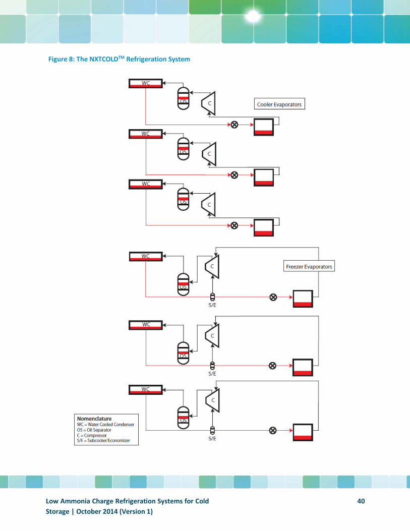
Figure 8: The NXTCOLDTM Refrigeration System
Low Ammonia Charge Refrigeration Systems for Cold Storage | October 2014 (Version 1)
40
Special Considerations
As noted previously, the typical installation of a NXTCOLDTM system will be on the roof of the facility. Structural and seismic considerations must be taken into account in the design of the facility. Weight loading of each unit is estimated to be between 40 and 60 pounds per square foot.
Ammonia Refrigerant Charge
As noted earlier, the ammonia charge for the NXTCOLDTM system is the lowest per ton of refrigeration of all systems under study in this report. The total charge for a facility with the requirements of the baseline system would be 385 pounds or 0.51 lbs/TR.
Energy Consumption
The estimated power consumption for the NXTCOLDTM on the basis of KW/Ton of Refrigeration for the generic system is 2.4 KW/TR.
Installed Cost
Even with a generic design serving as a basis of comparison, the installed cost of the system can vary significantly from one region of the country to the next based on structural requirements, labor rates, weather conditions, local codes etc. Nevertheless, the NXTCOLDTM system takes a great deal of guesswork away from installation costs in that the only major on-site installation variable involves preparation of the roof penetration rather than the actual installation cost of the package itself. With this in mind, installation costs for the generic design are estimated at $7,000 per ton of refrigeration.
Maintenance Cost
Similar to the Azane packages, the NXTCOLDTM systems are viewed to require less maintenance than any type of central system.
Maintenance Cost Vs. Baseline = Less
Summary
This white paper has reviewed 5 alternative industrial refrigeration systems, all of which are capable of providing the refrigeration requirements to a cold storage facility in place of the conventional pumped recirculated liquid system. The primary objective of this report was to examine systems which had the potential to significantly reduce the ammonia charge of a “typical” cold storage facility. Secondary objectives of the paper were to survey key variables such as energy consumption, installed cost, and maintenance cost. While data related to these variables is quite limited at this point in time, there is enough information in the public domain along with data provided by the various contributors to this document to draw some general conclusions:
Low Ammonia Charge Refrigeration Systems for Cold Storage | October 2014 (Version 1)
41
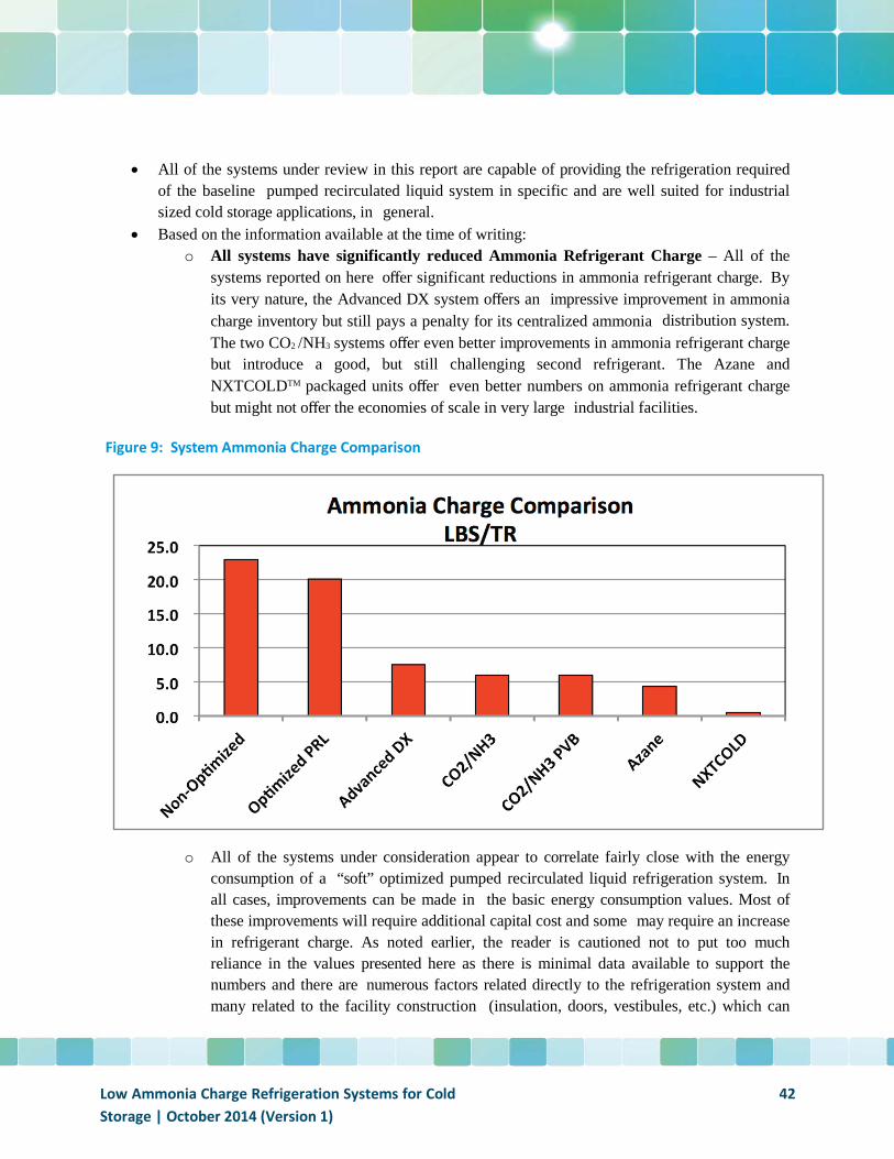
• All of the systems under review in this report are capable of providing the refrigeration required of the baseline pumped recirculated liquid system in specific and are well suited for industrial sized cold storage applications, in general.
• Based on the information available at the time of writing: o All systems have significantly reduced Ammonia Refrigerant Charge – All of the
systems reported on here offer significant reductions in ammonia refrigerant charge. By its very nature, the Advanced DX system offers an impressive improvement in ammonia charge inventory but still pays a penalty for its centralized ammonia distribution system. The two CO2 /NH3 systems offer even better improvements in ammonia refrigerant charge but introduce a good, but still challenging second refrigerant. The Azane and NXTCOLDTM packaged units offer even better numbers on ammonia refrigerant charge but might not offer the economies of scale in very large industrial facilities.
Figure 9: System Ammonia Charge Comparison
o All of the systems under consideration appear to correlate fairly close with the energy consumption of a “soft” optimized pumped recirculated liquid refrigeration system. In all cases, improvements can be made in the basic energy consumption values. Most of these improvements will require additional capital cost and some may require an increase in refrigerant charge. As noted earlier, the reader is cautioned not to put too much reliance in the values presented here as there is minimal data available to support the numbers and there are numerous factors related directly to the refrigeration system and many related to the facility construction (insulation, doors, vestibules, etc.) which can
Low Ammonia Charge Refrigeration Systems for Cold Storage | October 2014 (Version 1)
42
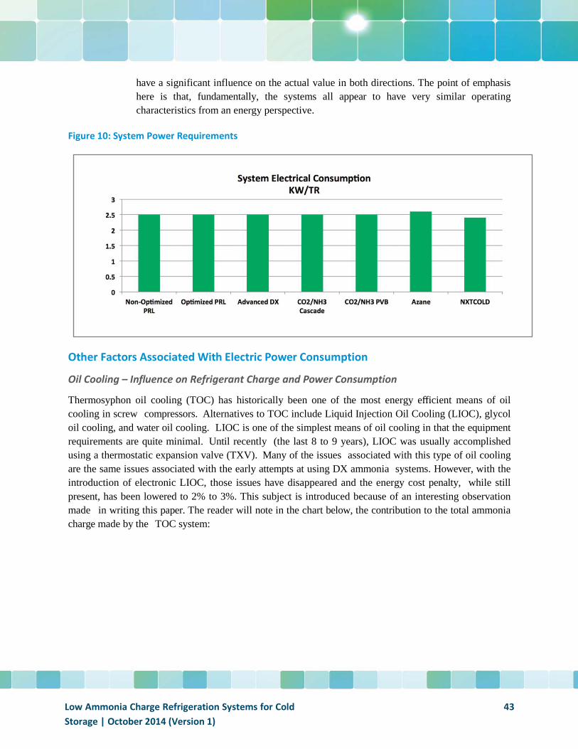
have a significant influence on the actual value in both directions. The point of emphasis here is that, fundamentally, the systems all appear to have very similar operating characteristics from an energy perspective.
Figure 10: System Power Requirements
Other Factors Associated With Electric Power Consumption
Oil Cooling – Influence on Refrigerant Charge and Power Consumption
Thermosyphon oil cooling (TOC) has historically been one of the most energy efficient means of oil cooling in screw compressors. Alternatives to TOC include Liquid Injection Oil Cooling (LIOC), glycol oil cooling, and water oil cooling. LIOC is one of the simplest means of oil cooling in that the equipment requirements are quite minimal. Until recently (the last 8 to 9 years), LIOC was usually accomplished using a thermostatic expansion valve (TXV). Many of the issues associated with this type of oil cooling are the same issues associated with the early attempts at using DX ammonia systems. However, with the introduction of electronic LIOC, those issues have disappeared and the energy cost penalty, while still present, has been lowered to 2% to 3%. This subject is introduced because of an interesting observation made in writing this paper. The reader will note in the chart below, the contribution to the total ammonia charge made by the TOC system:
Low Ammonia Charge Refrigeration Systems for Cold Storage | October 2014 (Version 1)
43
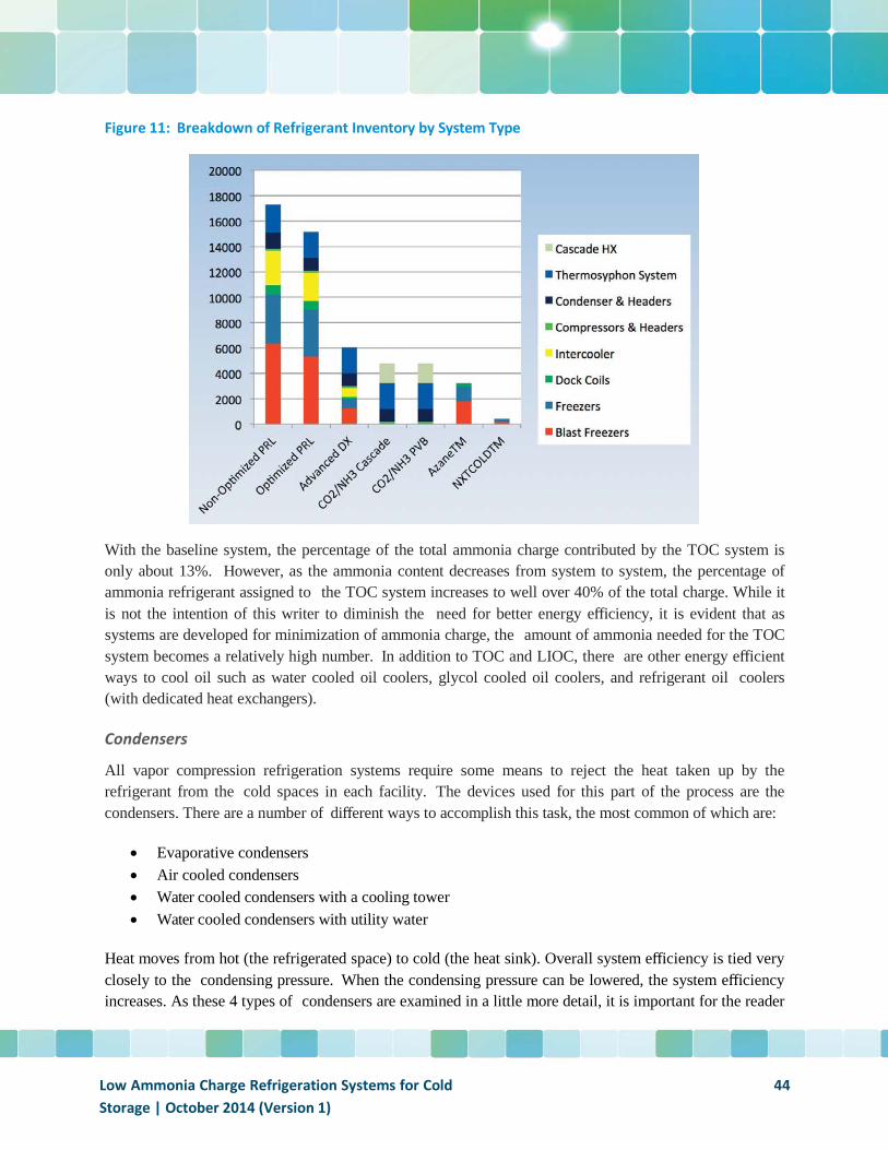
Figure 11: Breakdown of Refrigerant Inventory by System Type
With the baseline system, the percentage of the total ammonia charge contributed by the TOC system is only about 13%. However, as the ammonia content decreases from system to system, the percentage of ammonia refrigerant assigned to the TOC system increases to well over 40% of the total charge. While it is not the intention of this writer to diminish the need for better energy efficiency, it is evident that as systems are developed for minimization of ammonia charge, the amount of ammonia needed for the TOC system becomes a relatively high number. In addition to TOC and LIOC, there are other energy efficient ways to cool oil such as water cooled oil coolers, glycol cooled oil coolers, and refrigerant oil coolers (with dedicated heat exchangers).
Condensers
All vapor compression refrigeration systems require some means to reject the heat taken up by the refrigerant from the cold spaces in each facility. The devices used for this part of the process are the condensers. There are a number of different ways to accomplish this task, the most common of which are:
• Evaporative condensers • Air cooled condensers • Water cooled condensers with a cooling tower • Water cooled condensers with utility water
Heat moves from hot (the refrigerated space) to cold (the heat sink). Overall system efficiency is tied very closely to the condensing pressure. When the condensing pressure can be lowered, the system efficiency increases. As these 4 types of condensers are examined in a little more detail, it is important for the reader
Low Ammonia Charge Refrigeration Systems for Cold Storage | October 2014 (Version 1)
44
to keep this in mind. If the system has a high temperature heat sink (usually the ambient air temperature), the compressors are forced to compress the refrigerant to a higher temperature and the system’s efficiency suffers.
Evaporative condensers are the most common condensers in industrial refrigeration facilities and for the systems examined in this paper, the evaporative condenser would, typically, be the condenser of choice for the baseline PRL, the Advanced DX, the CO2 /NH3 Cascade, and the CO2 /NH3 PVB systems. They are typically very effective devices in all but extremely humid climates.
Air cooled condensers generally require higher condensing temperatures because the heat sink temperature is relatively high compared to the other devices noted above. This style of condenser may be the only one of choice in areas with limited water availability or very high water prices. The AzanechillerTM and AzanefreezerTM electric power consumption represent values based on air cooled condensers. The effectiveness of the condenser heat exchanger is of prime importance in limiting the temperature at which the refrigerant must be elevated in order to produce acceptable results.
The good news is that heat exchanger designs have improved dramatically over the past decade and the penalty previously paid for by using air cooled condensers has decreased. Additionally, unlike the other types of condensers which use water, no water treatment is required for air cooled condensers which greatly simplifies maintenance.
Water cooled condensers with a cooling tower operate in a similar fashion as evaporative condensers except that it is the water circuit which is being cooled by the cooling tower rather than the refrigerant. This arrangement makes relatively efficient use of the water as the majority of it is recycled back to the cooling system and doesn’t require excessive amounts of make-up water or large refrigerant charges. The NXTCOLDTM unit will, in most cases, use some version of this design.
Water cooled condensers with utility water are not very common for a number of reasons but are included in this discussion for the sake of completeness. In this particular example, water would be taken from the water utility or a well, sent to a small heat exchanger (usually a plate type heat exchanger or plate and shell), cool the refrigerant, and then sent to the storm drain. The best part about this design is that the condensing temperature is likely the lowest of all options and, therefore, the efficiency of the system can be quite high. The bad news is that this process requires a lot of water and can be very expensive from a utility cost perspective.
All systems can have a wide variation in installed cost. The reader is cautioned not to place too much weight in the values reported here for a number of reasons:
• Comparisons are made to the baseline pumped recirculated liquid system. While an argument can be made that this is a typical system, it is obvious from the information in Figure 1 that there is a wide variation in facility size in the cold storage industry. In addition to size, the type of cold storage facility can also vary significantly. These two factors along with location will have a large impact on installed cost.
Low Ammonia Charge Refrigeration Systems for Cold Storage | October 2014 (Version 1)
45
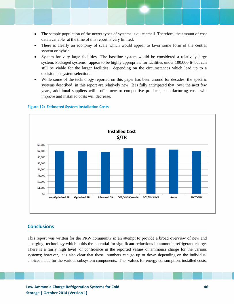
• The sample population of the newer types of systems is quite small. Therefore, the amount of cost data available at the time of this report is very limited.
• There is clearly an economy of scale which would appear to favor some form of the central system or hybrid
• System for very large facilities. The baseline system would be considered a relatively large system. Packaged systems appear to be highly appropriate for facilities under 100,000 ft2 but can still be viable for the larger facilities, depending on the circumstances which lead up to a decision on system selection.
• While some of the technology reported on this paper has been around for decades, the specific systems described in this report are relatively new. It is fully anticipated that, over the next few years, additional suppliers will offer new or competitive products, manufacturing costs will improve and installed costs will decrease.
Figure 12: Estimated System Installation Costs
Conclusions
This report was written for the PRW community in an attempt to provide a broad overview of new and emerging technology which holds the potential for significant reductions in ammonia refrigerant charge. There is a fairly high level of confidence in the reported values of ammonia charge for the various systems; however, it is also clear that these numbers can go up or down depending on the individual choices made for the various subsystem components. The values for energy consumption, installed costs,
Low Ammonia Charge Refrigeration Systems for Cold Storage | October 2014 (Version 1)
46
and maintenance costs represent the best estimates based on the information available at the time this paper was written. Over time, and with growing experience with the various systems, all of these values will be able to be determined with better resolution.
For those most interested in the subject matter of this paper, perhaps the most important conclusion to be taken away from this paper is that there are a number of viable and sound technologies available which can successfully address the growing concern over high ammonia refrigerant charges in cold storage facilities. From the information available, it does not appear that the other high priority variables (energy, installed cost, maintenance cost) will be negatively or positively impacted to any significant degree through the adoption of any of these new systems.
Finally, it must be emphasized that all of the numbers in this document are the best estimates for a hypothetical cold storage facility. Each operation will be different in terms of:
• Temperature levels • Blast freezing or no blast freezing • Cold storage or distribution • Space constraints • Etc.
The ultimate question in the minds of those committed to making a change to a low ammonia charge system may very well be, “which one is best?” As noted, each owner will have different sets of circumstances: different priorities, different growth scenarios, different types of facilities, different operating and operational constraints, and different budgets. What fits best for one organization might not be the right answer for the next one. It is has been the objective of this author and those who have contributed to this white paper that the information contained in this document will provide more insight and clarity into what certainly appears to be a rapidly evolving technology for the cold storage industry.
Low Ammonia Charge Refrigeration Systems for Cold Storage | October 2014 (Version 1)
47
References
(1) USDA, National Agricultural Statistics Service, “Capacity of Refrigerated Warehouses 2013 (January 2014)
(2) Welch, Jeff, DIRECT EXPANSION Evaporator Installation – Final Project Report, Welch Engineering Corporation 2013
(3) Nelson, Bruce I., DIRECT EXPANSION Ammonia Piping Handbook, Colmac Coil Manufacturing 2013
(4) Chapp, Terry L. , Direct Expansion – Ammonia Applications and Electronic Control, Presented at the 2008 RETA National Conference
(5) Danfoss, Industrial Refrigeration – Ammonia and CO2 Applications Handbook, September 2013 (6) VaCom Technologies, Pacific Gas and Electric Emerging Technologies Program Application
Assessment Report 0707 “Cascade CO2 /NH3 Refrigeration System Efficiency Study” March 30, 2009
(7) Pearson, Dr. S. Forbes, Charge Minimization, Presented at the IIAR 2012 Conference (8) Mumanachit, P., Reindl, D.T., Nellis, G.F. "Comparative Analysis of Low Temperature Industrial
Refrigeration Systems" University of Wisconsin published in the International Journal of Refrigeration 35 (2012)
Low Ammonia Charge Refrigeration Systems for Cold Storage | October 2014 (Version 1)
48