Embed Size (px)
Citation preview
LOW ANGLE ROPE RESCUE OPERATIONAL
Chapter 4: Anchor Systems
May 2007 Edition - 44 -
STATE FIRE STATE FIRE
CChhaapptteerr 44:: AAnncchhoorr SSyysstteemmss
Scope: This chapter serves as an introduction to anchor systems. Terminal Learning Objective (TLO): At the end of this chapter, the student will be aware of anchor selection and
anchor system construction. Enabling Learning Objectives (ELO): 1. Describe a personal fall arrest system 2. Describe considerations when selecting anchors 3. Describe the types of anchors 4. Demonstrate how to form a single loop, double loop, locking girth hitch (lark's foot) 5. Demonstrate how to form a single and double loop basket sling (three bight) 6. Demonstrate how to form a single and multi-loop anchor sling 7. Demonstrate how to form a wrap three pull two anchor sling 8. Demonstrate how to construct a two-point/three-point self-adjusting anchor system 9. Demonstrate how to construct a tagged anchor system 10. Demonstrate how to construct a 1-1-1 inline and triangle windlass 11. Demonstrate describe sling anchor attachments: prettied 12. Demonstrate describe single sling anchor attachments: open 13. Demonstrate describe multi-point self-adjusting anchor systems 14. Demonstrate describe windlassed picket systems
An anchor (also called an anchor point) is a stationary object capable of supporting the load attached to it. An anchor system is the rope, slings, and hardware used to attach a load to the anchor, and includes the anchor. The result of an inadequate anchor or anchor system is failure of the system. Therefore anchor selection and anchor system construction are fundamental skills for the rescuer.
California Code of Regulations, Title 8, Section 1670
Personal Fall Arrest Systems This standard requires that anchors be capable of supporting at least 5,000 pounds per employee attached or must be designed, installed, and used as part of a complete fall arrest system that maintains a safety factor of at least two and used under the supervision of a qualified person. The systems described in this manual have been tested and found to comply with this standard. However, the user is responsible for ensuring all components of the system used are strong enough for their application.
Considerations When Selecting Anchors When selecting an anchor several factors must be considered:
How much force will the anchor need to be able to hold?
What direction will the pull or force come from? A "nondirectional anchor" will withstand a pull
from any direction. Figure 4-1: Nondirectional Anchor
LOW ANGLE ROPE RESCUE OPERATIONAL
Chapter 4: Anchor Systems
May 2007 Edition - 45 -
STATE FIRE STATE FIRE
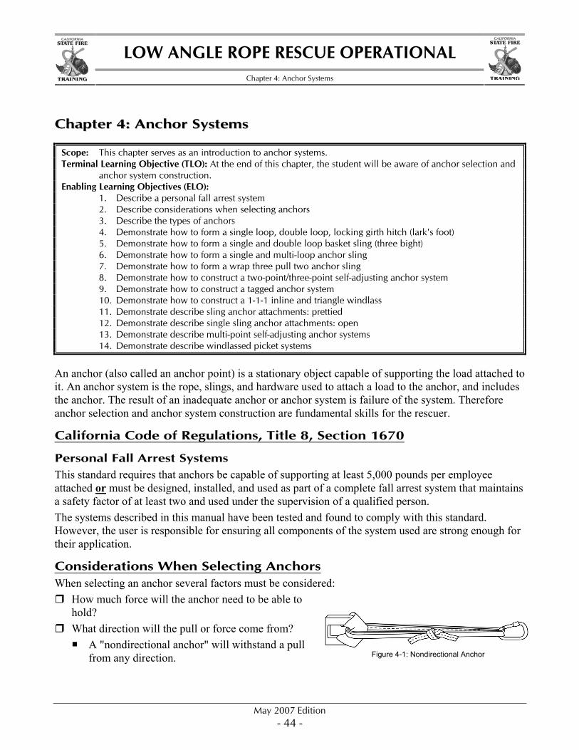
A "directional anchor" will fail if the load shifts to an unintended direction of pull.
Is there an adequate and safe working distance between the anchor, anchor system, and edge?
Does the anchor need to be padded to protect the anchor sling material from sharp edges, excessive heat, or caustic materials?
Types of Anchors
Natural Anchors Large living trees or solid rock.
Manufactured Anchors
Vehicles Potential anchor point
Preinstalled connect point. Have solid points to connect to:
Wheels. Rear exterior dual preferred.
Mitigate excessive heat and sharp edge conditions. Turn off engine.
Remove key if possible. Tag out (sign on steering wheel).
Set brake and chock wheels. Should not move vehicle during rescue operation. Light vehicles (pick-ups and other passenger types) may not be adequate.
Structural Components Utilize major structural components. Utilize well-established anchors on large machinery and equipment. Inspect potential anchors for rust, corrosion, weathering, and quality of installation. Consider spanning windows and door openings to create anchors.
Pickets Offer a portable, drivable set of anchors if the soil is available and adequate. Must be driven at an angle (approximately 15°) away from the load. The lower the windlass (if utilized) the stronger the system will be. Check for underground utilities before driving.
Figure 4-2: Directional Anchor
LOW ANGLE ROPE RESCUE OPERATIONAL
Chapter 4: Anchor Systems
May 2007 Edition - 46 -
STATE FIRE STATE FIRE
Others There are several other types of manufactured anchors that will not be covered in this class. These range from setting large and permanent anchor bolts in holes drilled in concrete in heavy rescue operations, to inserting very small and temporary anchoring devices unique to mountain rescue operations. These are specialized pieces of equipment that require additional training. This course will deal with anchor options that are more common to most low angle rescue operations.
Sling Anchor Attachments: Pretied To perform low angle rope rescue quickly and efficiently, anchors must be placed in service rapidly. Pretied slings can be used to accomplish this; eliminating the time taken to tie knots at the scene. Pretied sling attachments are formed with a length of webbing or lifeline that is tied into itself to create a continuous loop. Webbing is commonly pretied with an overhand bend. Lifeline is commonly pretied with a figure eight bend or a double overhand bend.
Advantages Quick to form around anchors. Easy to relocate. Quick to remove from anchors. Easy to increase the sling's strength by
doubling the loop.
Disadvantages Unable to be adjusted to larger anchors. May be weakened by changes in the direction
of pull.
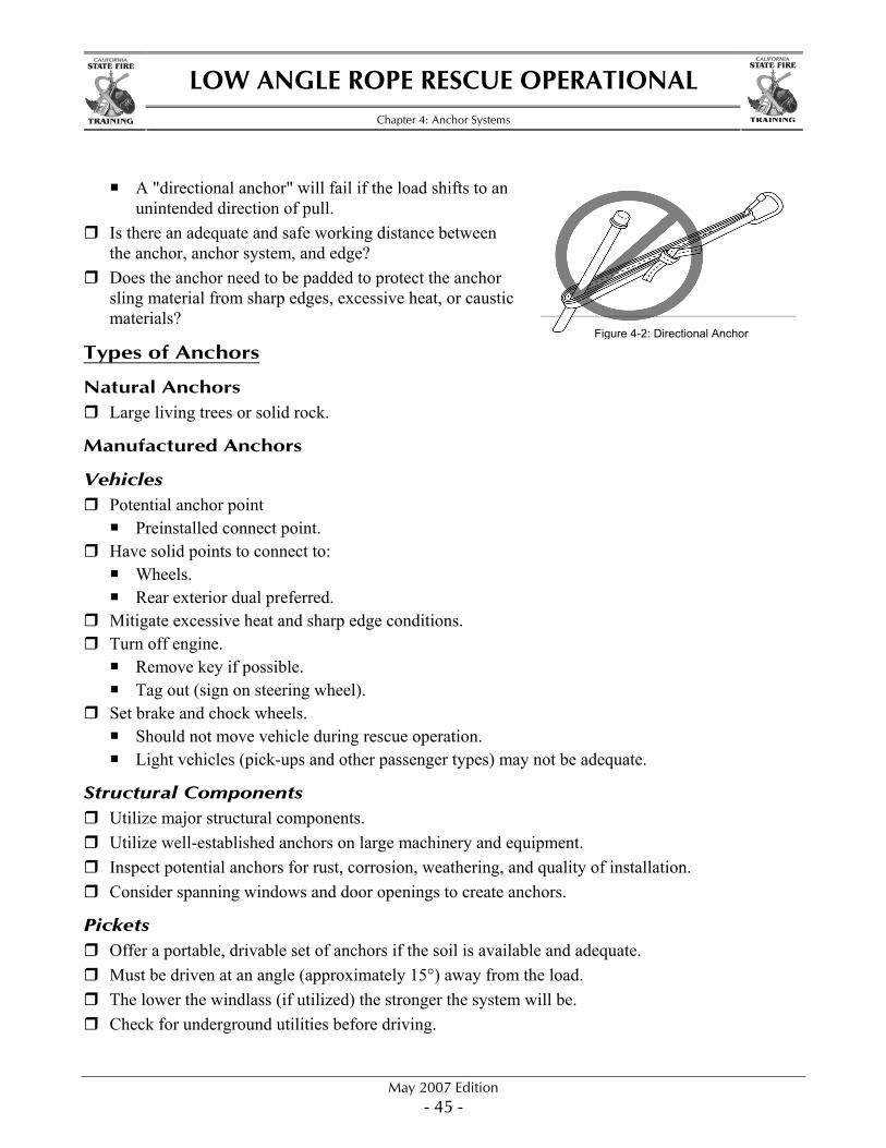
Forming the Double Loop
Figure 4-3: Step 1
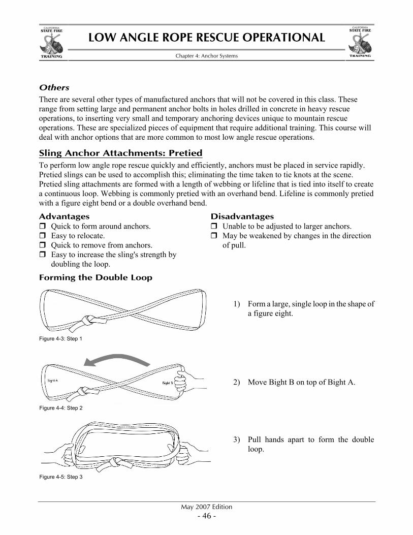
Figure 4-4: Step 2
Figure 4-5: Step 3
1) Form a large, single loop in the shape of
a figure eight. 2) Move Bight B on top of Bight A. 3) Pull hands apart to form the double
loop.
LOW ANGLE ROPE RESCUE OPERATIONAL
Chapter 4: Anchor Systems
May 2007 Edition - 47 -
STATE FIRE STATE FIRE
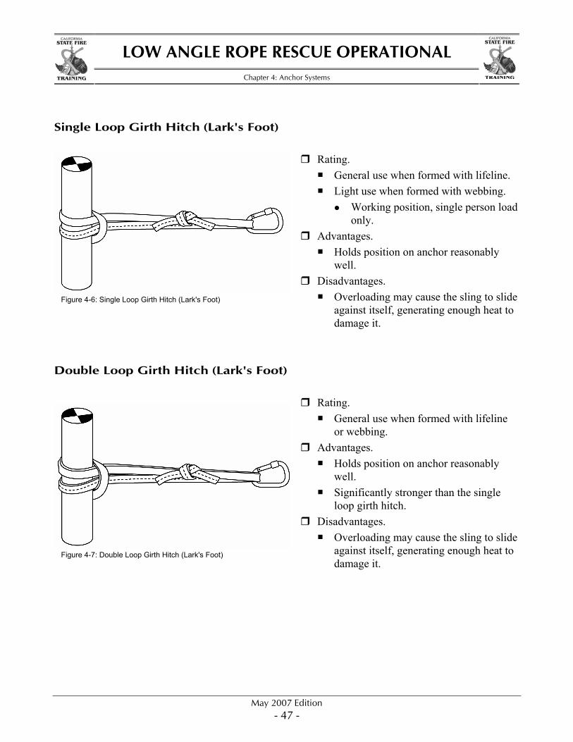
Single Loop Girth Hitch (Lark's Foot)
Rating. General use when formed with lifeline. Light use when formed with webbing.
Working position, single person load only.
Advantages. Holds position on anchor reasonably
well. Disadvantages.
Overloading may cause the sling to slide against itself, generating enough heat to damage it.
Double Loop Girth Hitch (Lark's Foot)
Rating. General use when formed with lifeline
or webbing. Advantages.
Holds position on anchor reasonably well.
Significantly stronger than the single loop girth hitch.
Disadvantages. Overloading may cause the sling to slide
against itself, generating enough heat to damage it.
Figure 4-6: Single Loop Girth Hitch (Lark's Foot)
Figure 4-7: Double Loop Girth Hitch (Lark's Foot)
LOW ANGLE ROPE RESCUE OPERATIONAL
Chapter 4: Anchor Systems
May 2007 Edition - 48 -
STATE FIRE STATE FIRE
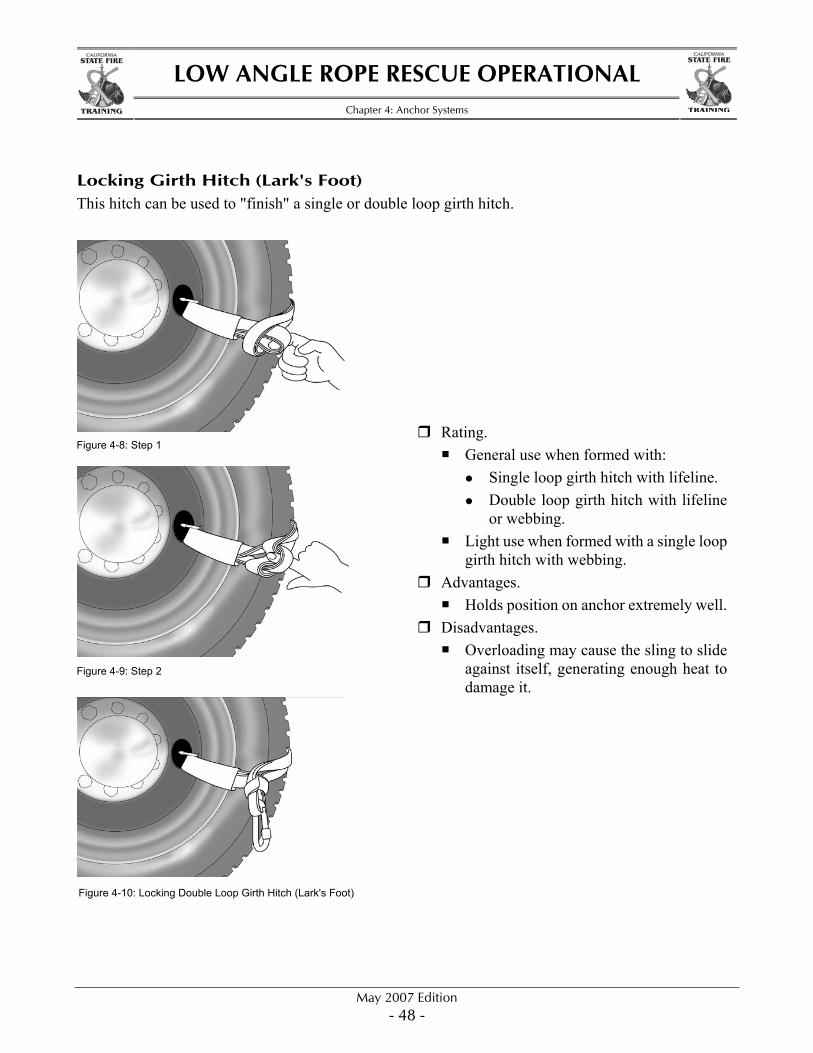
Locking Girth Hitch (Lark's Foot) This hitch can be used to "finish" a single or double loop girth hitch.
Figure 4-8: Step 1
Figure 4-9: Step 2
Figure 4-10: Locking Double Loop Girth Hitch (Lark's Foot)
Rating. General use when formed with:
Single loop girth hitch with lifeline. Double loop girth hitch with lifeline
or webbing. Light use when formed with a single loop
girth hitch with webbing. Advantages.
Holds position on anchor extremely well. Disadvantages.
Overloading may cause the sling to slide against itself, generating enough heat to damage it.
LOW ANGLE ROPE RESCUE OPERATIONAL
Chapter 4: Anchor Systems
May 2007 Edition - 49 -
STATE FIRE STATE FIRE
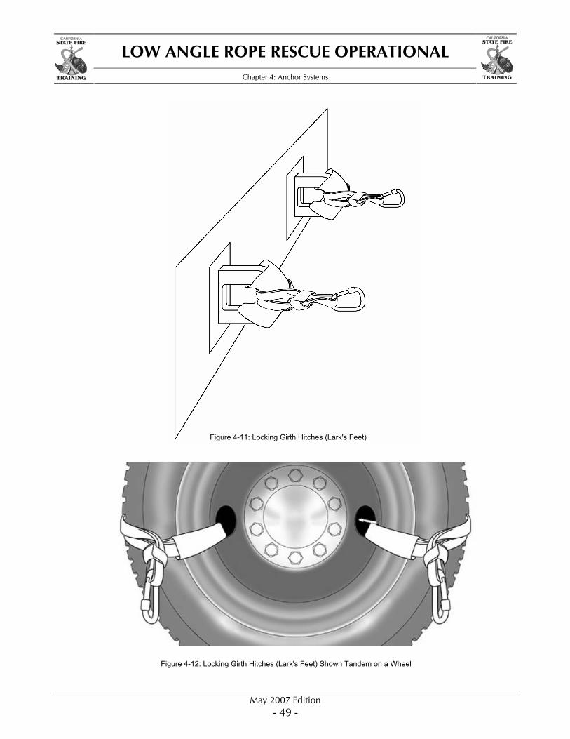
Figure 4-11: Locking Girth Hitches (Lark's Feet)
Figure 4-12: Locking Girth Hitches (Lark's Feet) Shown Tandem on a Wheel
LOW ANGLE ROPE RESCUE OPERATIONAL
Chapter 4: Anchor Systems
May 2007 Edition - 50 -
STATE FIRE STATE FIRE
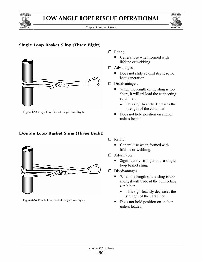
Single Loop Basket Sling (Three Bight) Rating.
General use when formed with lifeline or webbing.
Advantages. Does not slide against itself, so no
heat generation. Disadvantages.
When the length of the sling is too short, it will tri-load the connecting carabiner.
This significantly decreases the strength of the carabiner.
Does not hold position on anchor unless loaded.
Double Loop Basket Sling (Three Bight) Rating.
General use when formed with lifeline or webbing.
Advantages. Significantly stronger than a single
loop basket sling. Disadvantages.
When the length of the sling is too short, it will tri-load the connecting carabiner.
This significantly decreases the strength of the carabiner.
Does not hold position on anchor unless loaded.
Figure 4-13: Single Loop Basket Sling (Three Bight)
Figure 4-14: Double Loop Basket Sling (Three Bight)
LOW ANGLE ROPE RESCUE OPERATIONAL
Chapter 4: Anchor Systems
May 2007 Edition - 51 -
STATE FIRE STATE FIRE
Single Sling Anchor Attachments: Open When pre-established anchors are not available and anchors of unknown size are used, it may be necessary to use open slings. Open slings are lengths of webbing or lifeline that are left untied until needed. Open sling attachments are formed by wrapping a length of webbing or lifeline around an anchor and then tying it into itself. Webbing is commonly tied with an overhand bend. Lifeline is commonly tied with a figure eight bend or a double overhand bend.
Advantages Can be lengthened for larger anchors by tying slings together. Can be made stronger with multiple wraps. Can be adjusted more loosely or tightly by changing the length of the knot tail. Can adjust to changes of direction without loosing strength.
Disadvantages Slow to form around anchors. Difficult to relocate (requires untying and retying a knot). Slow to remove from an anchor. Do not provide a stationary directional anchor point.
Types of Single Sling Attachments: Open
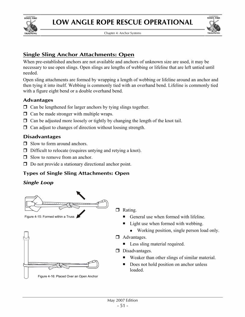
Single Loop
Rating. General use when formed with lifeline. Light use when formed with webbing.
Working position, single person load only. Advantages.
Less sling material required. Disadvantages.
Weaker than other slings of similar material. Does not hold position on anchor unless
loaded. Figure 4-16: Placed Over an Open Anchor
Figure 4-15: Formed within a Truss
LOW ANGLE ROPE RESCUE OPERATIONAL
Chapter 4: Anchor Systems
May 2007 Edition - 52 -
STATE FIRE STATE FIRE
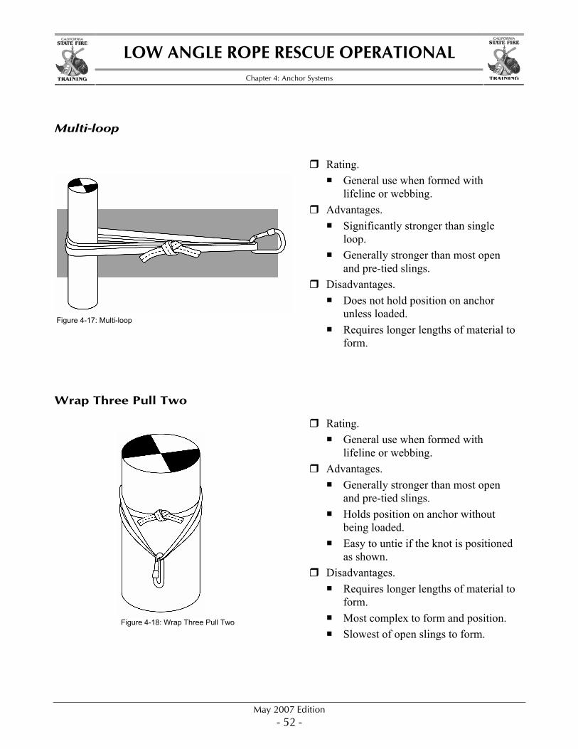
Multi-loop
Rating. General use when formed with
lifeline or webbing. Advantages.
Significantly stronger than single loop.
Generally stronger than most open and pre-tied slings.
Disadvantages. Does not hold position on anchor
unless loaded. Requires longer lengths of material to
form.
Wrap Three Pull Two Rating.
General use when formed with lifeline or webbing.
Advantages. Generally stronger than most open
and pre-tied slings. Holds position on anchor without
being loaded. Easy to untie if the knot is positioned
as shown. Disadvantages.
Requires longer lengths of material to form.
Most complex to form and position. Slowest of open slings to form.
Figure 4-17: Multi-loop
Figure 4-18: Wrap Three Pull Two
LOW ANGLE ROPE RESCUE OPERATIONAL
Chapter 4: Anchor Systems
May 2007 Edition - 53 -
STATE FIRE STATE FIRE
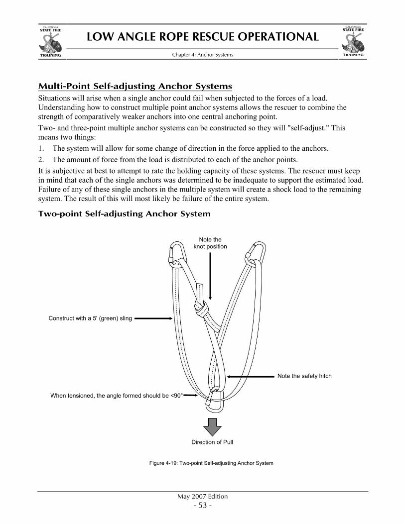
Multi-Point Self-adjusting Anchor Systems Situations will arise when a single anchor could fail when subjected to the forces of a load. Understanding how to construct multiple point anchor systems allows the rescuer to combine the strength of comparatively weaker anchors into one central anchoring point. Two- and three-point multiple anchor systems can be constructed so they will "self-adjust." This means two things: 1. The system will allow for some change of direction in the force applied to the anchors. 2. The amount of force from the load is distributed to each of the anchor points. It is subjective at best to attempt to rate the holding capacity of these systems. The rescuer must keep in mind that each of the single anchors was determined to be inadequate to support the estimated load. Failure of any of these single anchors in the multiple system will create a shock load to the remaining system. The result of this will most likely be failure of the entire system.
Two-point Self-adjusting Anchor System
Figure 4-19: Two-point Self-adjusting Anchor System
Direction of Pull
Construct with a 5' (green) sling
Note the safety hitch
Note the knot position
When tensioned, the angle formed should be <90°
LOW ANGLE ROPE RESCUE OPERATIONAL
Chapter 4: Anchor Systems
May 2007 Edition - 54 -
STATE FIRE STATE FIRE
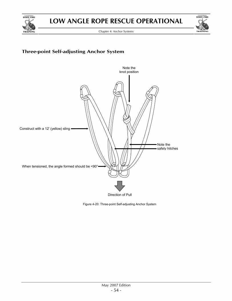
Three-point Self-adjusting Anchor System
Figure 4-20: Three-point Self-adjusting Anchor System
Construct with a 12' (yellow) sling
Note the knot position
When tensioned, the angle formed should be <90°
Direction of Pull
Note the safety hitches
LOW ANGLE ROPE RESCUE OPERATIONAL
Chapter 4: Anchor Systems
May 2007 Edition - 55 -
STATE FIRE STATE FIRE
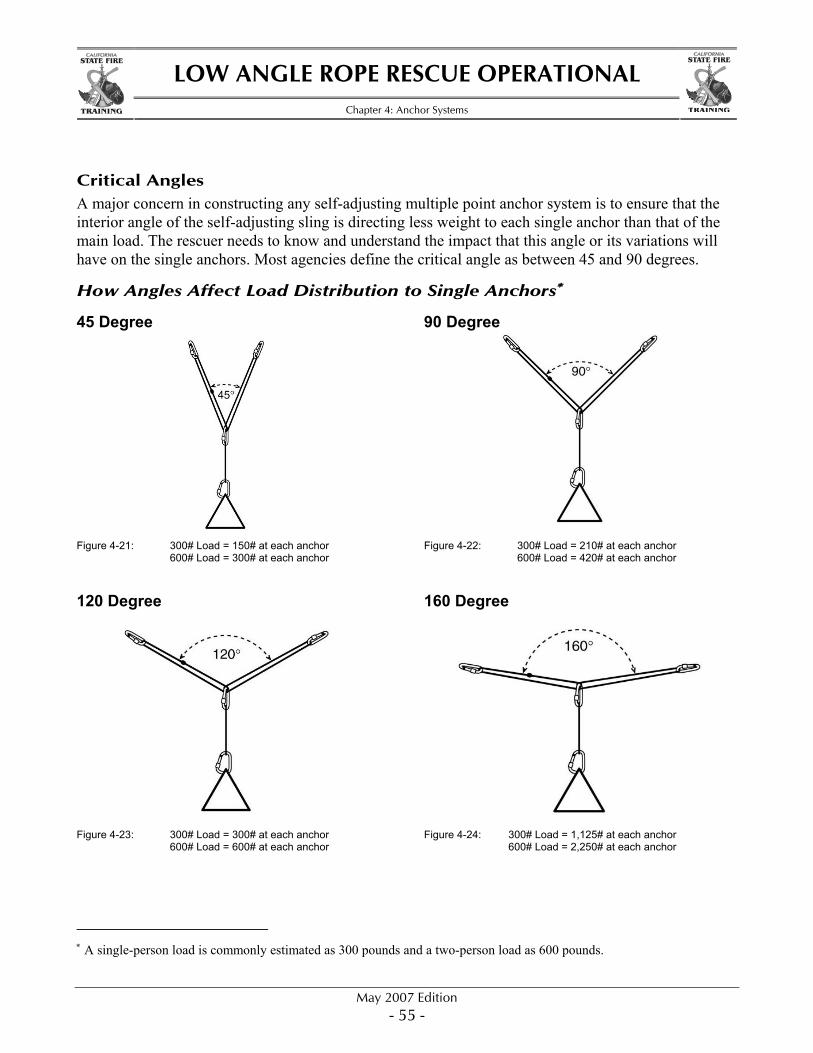
Critical Angles A major concern in constructing any self-adjusting multiple point anchor system is to ensure that the interior angle of the self-adjusting sling is directing less weight to each single anchor than that of the main load. The rescuer needs to know and understand the impact that this angle or its variations will have on the single anchors. Most agencies define the critical angle as between 45 and 90 degrees.
How Angles Affect Load Distribution to Single Anchors∗
45 Degree 90 Degree
Figure 4-21: 300# Load = 150# at each anchor 600# Load = 300# at each anchor
Figure 4-22: 300# Load = 210# at each anchor 600# Load = 420# at each anchor
120 Degree 160 Degree
Figure 4-23: 300# Load = 300# at each anchor 600# Load = 600# at each anchor
Figure 4-24: 300# Load = 1,125# at each anchor 600# Load = 2,250# at each anchor
∗ A single-person load is commonly estimated as 300 pounds and a two-person load as 600 pounds.
LOW ANGLE ROPE RESCUE OPERATIONAL
Chapter 4: Anchor Systems
May 2007 Edition - 56 -
STATE FIRE STATE FIRE
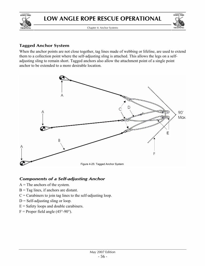
Tagged Anchor System When the anchor points are not close together, tag lines made of webbing or lifeline, are used to extend them to a collection point where the self-adjusting sling is attached. This allows the legs on a self-adjusting sling to remain short. Tagged anchors also allow the attachment point of a single point anchor to be extended to a more desirable location.
Components of a Self-adjusting Anchor A = The anchors of the system. B = Tag lines, if anchors are distant. C = Carabiners to join tag lines to the self-adjusting loop. D = Self-adjusting sling or loop. E = Safety loops and double carabiners. F = Proper field angle (45°-90°).
E
Figure 4-25: Tagged Anchor System
LOW ANGLE ROPE RESCUE OPERATIONAL
Chapter 4: Anchor Systems
May 2007 Edition - 57 -
STATE FIRE STATE FIRE
Windlassed Picket Systems In most situations, anchors of some type can be found. A big fine tree, a big fine rock, apparatus components, or structural components usually can be identified and used. However, there are situations when none of the above is available, or they are not positioned sufficiently in line with the incident to be effective. Being able to utilize picket systems may be the solution to this problem.
Ratings General use when in configurations of three and used in hard, compact soil.
Field testing shows over 5,000 pounds holding power. Light use (work positioning only, single person load) if single picket is used in hard, compact soil.
The Army Corps of Engineers rates a single picket at 700 pounds holding power.
Advantages Can be carried by rescue personnel to remote locations. Can predetermine the specific location to build the anchor system.
Disadvantages Strength and availability is dependent on soil type. Can be time consuming to set up. Can damage underground utilities. May be difficult to remove.
Common Specifications for Pickets 48" x 1" cold rolled steel.
Common Specifications for Tensioning Devices Usually a smaller size than a picket. 18"–24" long, ½"–¾" diameter.
System Set-up Each picket should be in a straight line with the direction of the load. Each picket should be driven at a 15° angle, tilted away from the load, to maximize its holding
power. Driven 24"–36" into the soil. Spaced one picket length apart from each other. The pickets of these systems are connected to each other with lengths lifeline or webbing. This
connecting technique is referred to a windlass.
The two types of windlass picket systems covered in this course are 1-1-1 Inline 1-1-1 Triangle

LOW ANGLE ROPE RESCUE OPERATIONAL
Chapter 4: Anchor Systems
May 2007 Edition - 58 -
STATE FIRE STATE FIRE
The Steps to Form a Windlass
1. Secure the end of the windlass material to the base of the front picket, approximately 2"–6" from ground level with a clove hitch or round turn and two half hitches.
2. Form a series of wraps around the base of one rear picket and the tie off point of the front picket and secure the end of the windlass material to either picket with a clove hitch or round turn and two half hitches. • Rope Minimum of two wraps (a 20-foot length should be adequate) • Webbing Minimum of four wraps (two 20-foot lengths of webbing tied together should be
adequate) • Some teams will have 36- to 40-foot lengths of webbing prebagged for windlass material. It is
common to see orange or a nonstandard color of webbing for this purpose. 3. Tighten the windlasses by inserting a tensioning device between the wraps and turning it, this will
cause the loops to twist and tighten. 4. Continue to tighten until the front picket starts to move. 5. Secure the tensioning device by driving it into, or placing it on, the ground.
Figure 4-26: Step 1
Figure 4-28: Step 3 Figure 4-29: Step 4
Figure 4-27: Step 2
LOW ANGLE ROPE RESCUE OPERATIONAL
Chapter 4: Anchor Systems
May 2007 Edition - 59 -
STATE FIRE STATE FIRE
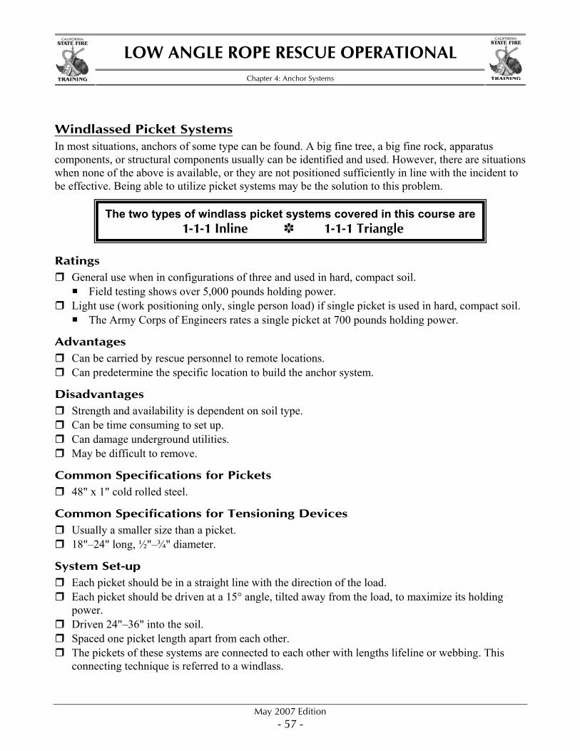
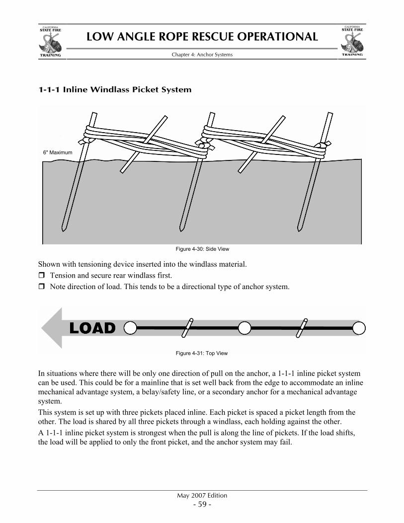
1-1-1 Inline Windlass Picket System
Shown with tensioning device inserted into the windlass material. Tension and secure rear windlass first. Note direction of load. This tends to be a directional type of anchor system.
In situations where there will be only one direction of pull on the anchor, a 1-1-1 inline picket system can be used. This could be for a mainline that is set well back from the edge to accommodate an inline mechanical advantage system, a belay/safety line, or a secondary anchor for a mechanical advantage system. This system is set up with three pickets placed inline. Each picket is spaced a picket length from the other. The load is shared by all three pickets through a windlass, each holding against the other. A 1-1-1 inline picket system is strongest when the pull is along the line of pickets. If the load shifts, the load will be applied to only the front picket, and the anchor system may fail.
Figure 4-31: Top View
Figure 4-30: Side View
6" Maximum
LOW ANGLE ROPE RESCUE OPERATIONAL
Chapter 4: Anchor Systems
May 2007 Edition - 60 -
STATE FIRE STATE FIRE
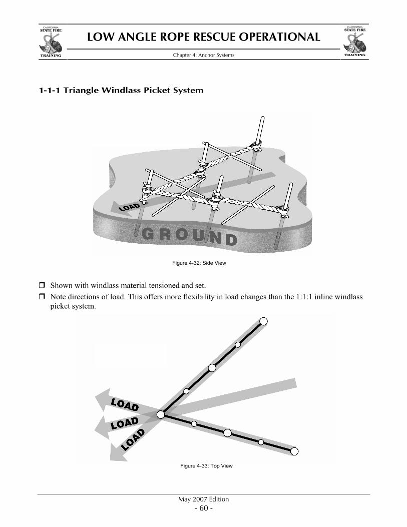
1-1-1 Triangle Windlass Picket System
Shown with windlass material tensioned and set. Note directions of load. This offers more flexibility in load changes than the 1:1:1 inline windlass
picket system.
Figure 4-32: Side View
Figure 4-33: Top View