Embed Size (px)
Citation preview
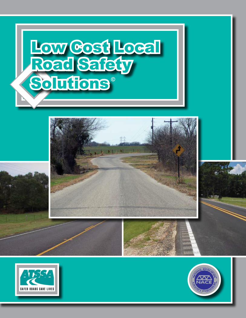
Solutions
Low Cost LocalRoad Safety
©
Copyright © 2006 The American Traffic Safety Services Association. Revised March 2006.
For additional copies visit the Online Store of ATSSA.com, call the Products Department at (877) 642-4637 or write to: ATSSA15 Riverside Parkway, Suite 100Fredericksburg, VA 22406
To order additional copies of Low Cost Local Road Safety Solutions at $19.95 each, e-mail [email protected], or call (877) 642-4637, ext. 135. A .pdf version of this book is available in the “Members Only” section of ATSSA.com.
Copies are free to ATSSA and NACE members.
For the past decade or more, the majority of motor vehicle fatalities in the United States have occurred on two-lane rural roads. In December 2005, the National Highway Traffic Safety Administration released a new report, Contrasting Rural and Urban Fatal Crashes 1994 – 2003. That report noted that from 1994 – 2003 there were 372,738 fatal crashes on U.S. roadways. Of those, some 218,539, or 58.6%, occurred on rural roads. During the same period, the rural fatality rate was 2.4 per 100 million vehicle miles traveled. The corresponding urban fatality rate is 1.0.
The Safe, Accountable, Flexible, Efficient Transportation Equity Act – A Legacy for Users (SAFETEA-LU) provides federal funds to address safety issues on our nation’s most dangerous roadways. SAFETEA-LU provides $90 million annually over four years as a set-aside under the Highway Safety Improvement Program (HSIP). While these funds are to be administered by state Departments of Transportation, Congress has directed that they be targeted at rural roads that have fatality rates that exceed statewide averages.
Although a positive start, SAFETEA-LU’s funding level for this program will not enable roadway safety practitioners to solve all of our nation’s local roadway safety problems. Therefore, it will be important for both state and local governments to stretch these funds to gain the maximum benefit or return on investment. The American Traffic Safety Services Association (ATSSA) and the National Association of County Engineers (NACE) formed a partnership to develop a tool to help local jurisdictions focus on proven low cost safety solutions. This publication, Low Cost Local Road Safety Solutions, is the result of that partnership. While we focused our efforts on solutions that could be applied in rural locations, many of the case study methodologies are entirely appropriate for urbanized areas.
The development of this publication was made possible through funding provided by ATSSA. The Texas Transportation Institute (TTI) was engaged to synthesize existing research and develop case studies about the various solutions presented here. NACE provided technical input and kept us on course to keep our focus on real solutions for local roads.
We hope that the examples that are provided are of sufficiently low cost that they might be considered and implemented by local jurisdictions even if federal funding under the HSIP is not immediately available.
ATSSA’s core purpose is To Advance Roadway Safety. We believe that if a single life can be saved through this project the effort will have been worthwhile.
INTRODUCTION
i
This publication was made possible through an allocation of funding provided by the Board of Directors of the American Traffic Safety Services Association (ATSSA). The Texas Transportation Institute undertook a synthesis of existing technical research and the development of the case studies. ATSSA would specifically like to recognize principal investigator Melisa D. Finley, P.E., Assistant Research Engineer.
Identification, review and refinement of the individual case studies was guided by a Local Roads Program Advisory Group comprised of the following individuals:
Bob FurnasPresidentMunicipal Supply & Sign Co.Naples, Florida
Anthony R. Giancola, P.E.Executive DirectorNational Association of County EngineersWashington, D.C.
James KalchbrennerEastern Regional Sales ManagerDavidson Traffic Control ProductsFiltrona ExtrusionWest Nyack, NewYork
David McKeeDirector, Technical Assistance CenterAmerican Traffic Safety Services AssociationFredericksburg, Virginia
Neal MoonTime Striping, Inc.Van Buren, Arizona
Fred Ranck, P.E., P.T.O.E.Safety & Geometric EngineerFederal Highway AdministrationOlympia Fields, Illinois
ATSSA thanks each of these individuals for their time, patience and tenacity in moving this project forward.
ACKNOWLEDGEMENTS
ii
Sign and Pavement Marking Improvements Reduce Crashes
Post-Mounted Delineators and Chevrons Reduce Crashes and Speeds in Curves
In-Street Pedestrian Crossing Signs Increase Driver Yielding Compliance Rear-Facing Flashing Beacons on School Speed Limit Signs Have a Positive Effect on Speeds Speed Displays Reduce Traffic Speeds and Increase Speed Limit Compliance
Edge Lines on Two-Lane Roadways Improve Safety Wider Longitudinal Pavement Markings Improve Safety
Raised Pavement Markers Reduce Crashes on Two-Lane Roadways
Shoulder and Edge Line Rumble Strips Reduce Run-Off-Road Crashes
Centerline Rumble Strips Reduce Head-On and Sideswipe Crashes
Pavement Markings Over Rumble Strips (Rumble Stripes) Improve Pavement Marking Visibility
On-Pavement Horizontal Signing: Information in the Driver’s Line-of-Sight
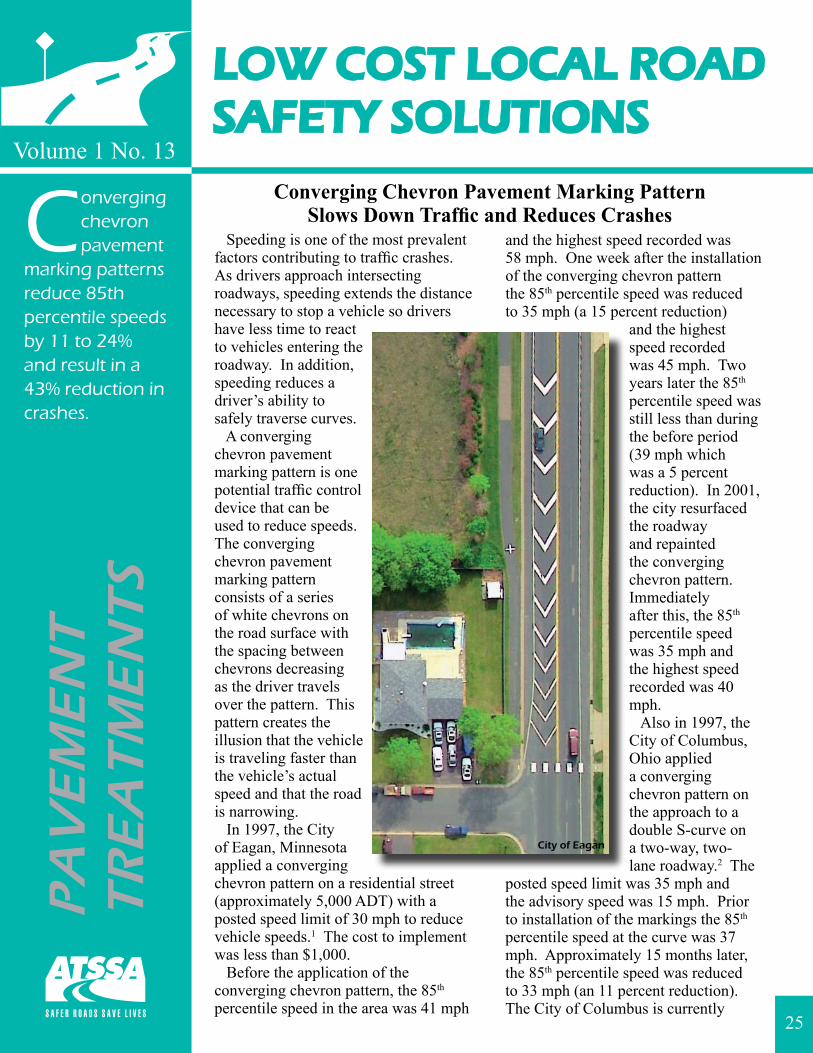
Converging Chevron Pavement Marking Pattern Slows Down Traffic and Reduces Crashes
Longitudinal Channelizers Reduce Gate Violations at Highway-Railroad Grade Crossings
Roadside Cable Barrier Reduces the Severity of Run-Off-Road Crashes
Cable Median Barrier Reduces Crossover Crashes
How Do I Conduct a Crash Study? Additional Resources
1
3
5
7
9
11
13
15
17
19
21
23
25
27
29
31
33
37
TABLE OF CONTENTS
iii

LOW COST LOCAL ROADSAFETY SOLUTIONS
Sign and Pavement Marking Improvements Reduce Crashes
Volume 1 No. 1
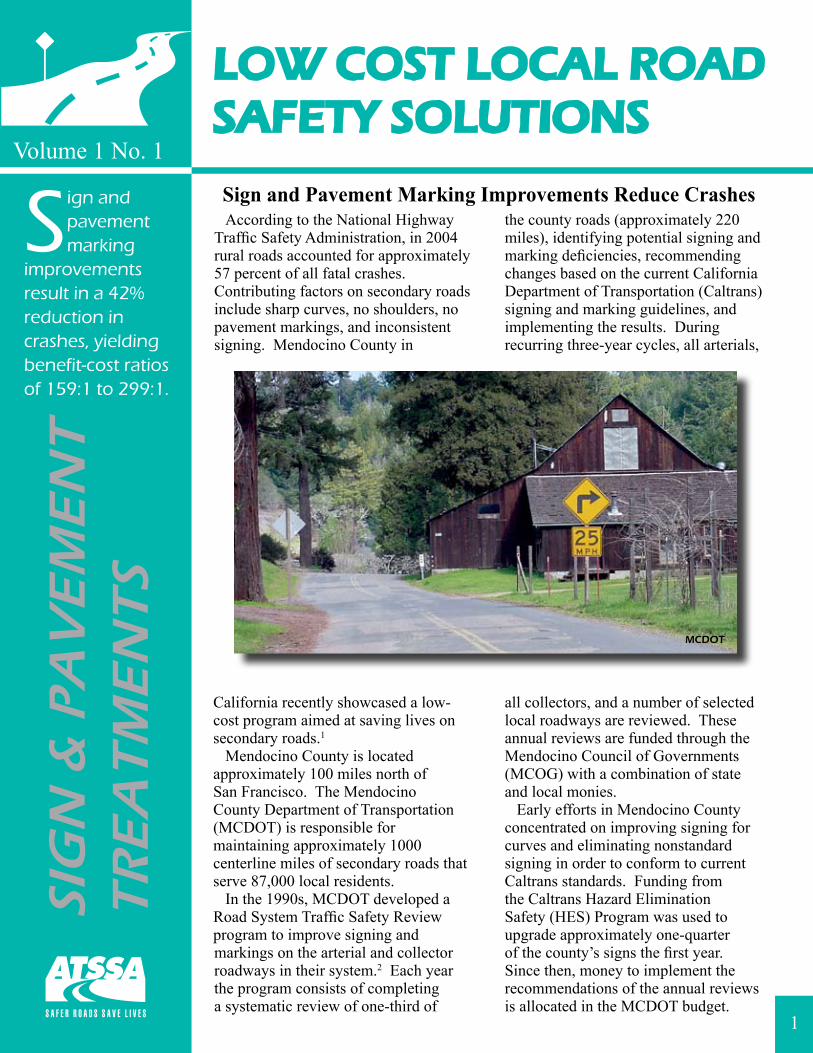
According to the National Highway Traffic Safety Administration, in 2004 rural roads accounted for approximately 57 percent of all fatal crashes. Contributing factors on secondary roads include sharp curves, no shoulders, no pavement markings, and inconsistent signing. Mendocino County in
California recently showcased a low-cost program aimed at saving lives on secondary roads.1
Mendocino County is located approximately 100 miles north of San Francisco. The Mendocino County Department of Transportation (MCDOT) is responsible for maintaining approximately 1000 centerline miles of secondary roads that serve 87,000 local residents. In the 1990s, MCDOT developed a Road System Traffic Safety Review program to improve signing and markings on the arterial and collector roadways in their system.2 Each year the program consists of completing a systematic review of one-third of
the county roads (approximately 220 miles), identifying potential signing and marking deficiencies, recommending changes based on the current California Department of Transportation (Caltrans) signing and marking guidelines, and implementing the results. During recurring three-year cycles, all arterials,
all collectors, and a number of selected local roadways are reviewed. These annual reviews are funded through the Mendocino Council of Governments (MCOG) with a combination of state and local monies. Early efforts in Mendocino County concentrated on improving signing for curves and eliminating nonstandard signing in order to conform to current Caltrans standards. Funding from the Caltrans Hazard Elimination Safety (HES) Program was used to upgrade approximately one-quarter of the county’s signs the first year. Since then, money to implement the recommendations of the annual reviews is allocated in the MCDOT budget.
SIG
N &
PA
VE
ME
NT
TR
EA
TM
EN
TS
Sign and pavement marking
improvements result in a 42% reduction in crashes, yielding benefit-cost ratios of 159:1 to 299:1.
1
For more information on Low Cost Local Road Safety Solutions visit http://www.atssa.com.
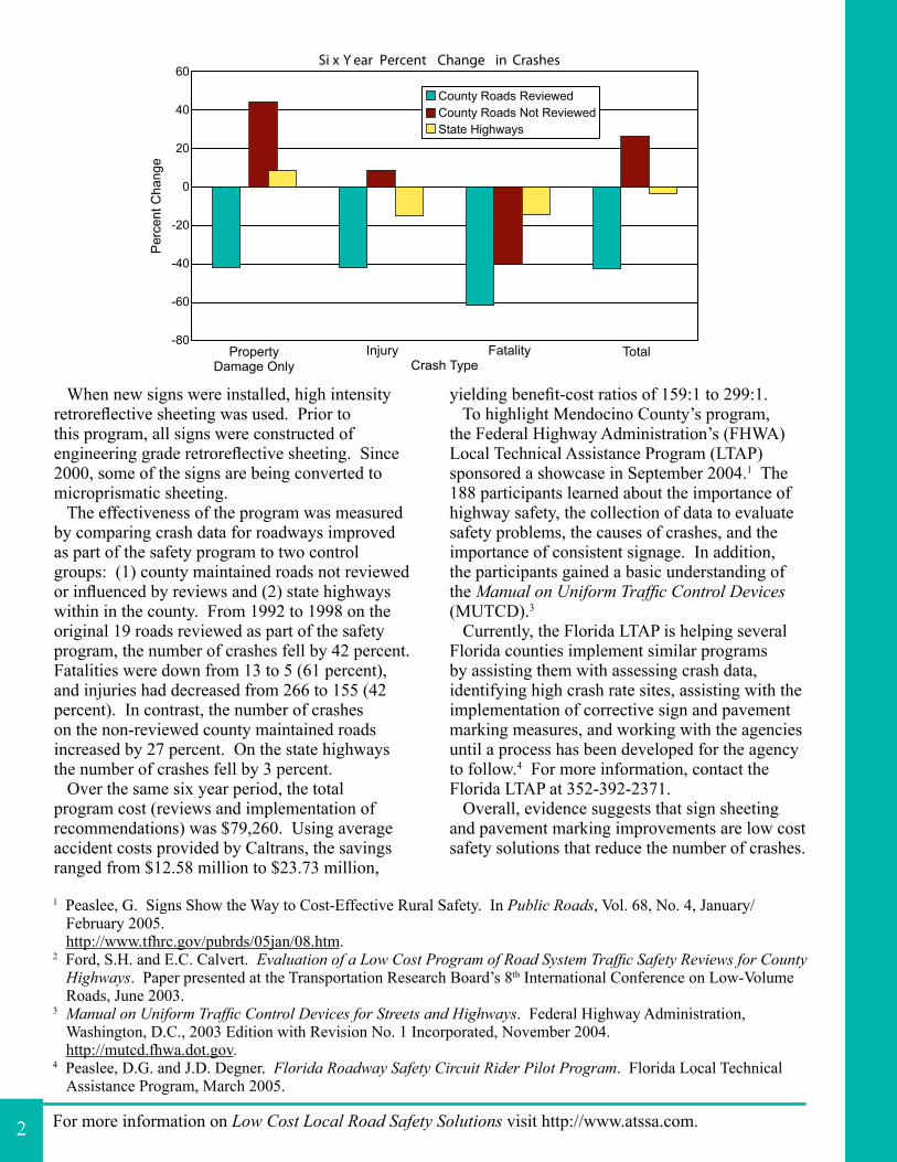
When new signs were installed, high intensity retroreflective sheeting was used. Prior to this program, all signs were constructed of engineering grade retroreflective sheeting. Since 2000, some of the signs are being converted to microprismatic sheeting. The effectiveness of the program was measured by comparing crash data for roadways improved as part of the safety program to two control groups: (1) county maintained roads not reviewed or influenced by reviews and (2) state highways within in the county. From 1992 to 1998 on the original 19 roads reviewed as part of the safety program, the number of crashes fell by 42 percent. Fatalities were down from 13 to 5 (61 percent), and injuries had decreased from 266 to 155 (42 percent). In contrast, the number of crashes on the non-reviewed county maintained roads increased by 27 percent. On the state highways the number of crashes fell by 3 percent. Over the same six year period, the total program cost (reviews and implementation of recommendations) was $79,260. Using average accident costs provided by Caltrans, the savings ranged from $12.58 million to $23.73 million,
yielding benefit-cost ratios of 159:1 to 299:1. To highlight Mendocino County’s program, the Federal Highway Administration’s (FHWA) Local Technical Assistance Program (LTAP) sponsored a showcase in September 2004.1 The 188 participants learned about the importance of highway safety, the collection of data to evaluate safety problems, the causes of crashes, and the importance of consistent signage. In addition, the participants gained a basic understanding of the Manual on Uniform Traffic Control Devices (MUTCD).3
Currently, the Florida LTAP is helping several Florida counties implement similar programs by assisting them with assessing crash data, identifying high crash rate sites, assisting with the implementation of corrective sign and pavement marking measures, and working with the agencies until a process has been developed for the agency to follow.4 For more information, contact the Florida LTAP at 352-392-2371. Overall, evidence suggests that sign sheeting and pavement marking improvements are low cost safety solutions that reduce the number of crashes.
1 Peaslee, G. Signs Show the Way to Cost-Effective Rural Safety. In Public Roads, Vol. 68, No. 4, January/ February 2005. http://www.tfhrc.gov/pubrds/05jan/08.htm.
2 Ford, S.H. and E.C. Calvert. Evaluation of a Low Cost Program of Road System Traffic Safety Reviews for County Highways. Paper presented at the Transportation Research Board’s 8th International Conference on Low-Volume Roads, June 2003.
3 Manual on Uniform Traffic Control Devices for Streets and Highways. Federal Highway Administration, Washington, D.C., 2003 Edition with Revision No. 1 Incorporated, November 2004. http://mutcd.fhwa.dot.gov.
4 Peaslee, D.G. and J.D. Degner. Florida Roadway Safety Circuit Rider Pilot Program. Florida Local Technical Assistance Program, March 2005.
2
PropertyDamage Only
Injury Fatality TotalCrash Type
Si x Y ear Percent Change in Crashes
County Roads ReviewedCounty Roads Not ReviewedState Highways
PercentChange
60
40
20
0
-20
-40
-60
-80
LOW COST LOCAL ROADSAFETY SOLUTIONS
Volume 1 No. 2
Crash studies show that post-
mounted delineators and chevrons can reduce run-off-road crashes by up to 58% and 31%, respectively.
SIG
NS
Post-Mounted Delineators and ChevronsReduce Crashes and Speeds in Curves
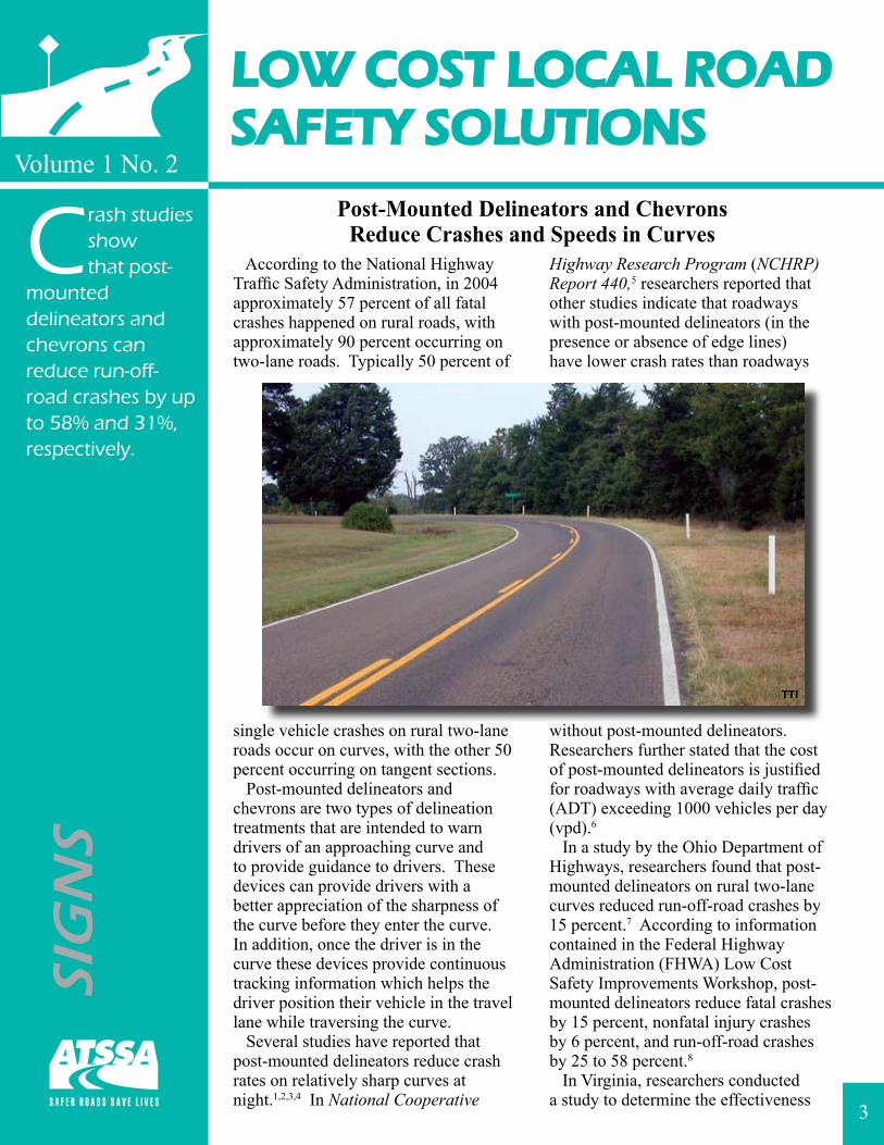
According to the National Highway Traffic Safety Administration, in 2004 approximately 57 percent of all fatal crashes happened on rural roads, with approximately 90 percent occurring on two-lane roads. Typically 50 percent of
single vehicle crashes on rural two-lane roads occur on curves, with the other 50 percent occurring on tangent sections. Post-mounted delineators and chevrons are two types of delineation treatments that are intended to warn drivers of an approaching curve and to provide guidance to drivers. These devices can provide drivers with a better appreciation of the sharpness of the curve before they enter the curve. In addition, once the driver is in the curve these devices provide continuous tracking information which helps the driver position their vehicle in the travel lane while traversing the curve. Several studies have reported that post-mounted delineators reduce crash rates on relatively sharp curves at night.1,2,3,4 In National Cooperative
Highway Research Program (NCHRP) Report 440,5 researchers reported that other studies indicate that roadways with post-mounted delineators (in the presence or absence of edge lines) have lower crash rates than roadways
without post-mounted delineators. Researchers further stated that the cost of post-mounted delineators is justified for roadways with average daily traffic (ADT) exceeding 1000 vehicles per day (vpd).6
In a study by the Ohio Department of Highways, researchers found that post-mounted delineators on rural two-lane curves reduced run-off-road crashes by 15 percent.7 According to information contained in the Federal Highway Administration (FHWA) Low Cost Safety Improvements Workshop, post-mounted delineators reduce fatal crashes by 15 percent, nonfatal injury crashes by 6 percent, and run-off-road crashes by 25 to 58 percent.8
In Virginia, researchers conducted a study to determine the effectiveness 3
TTI
For more information on Low Cost Local Road Safety Solutions visit http://www.atssa.com.
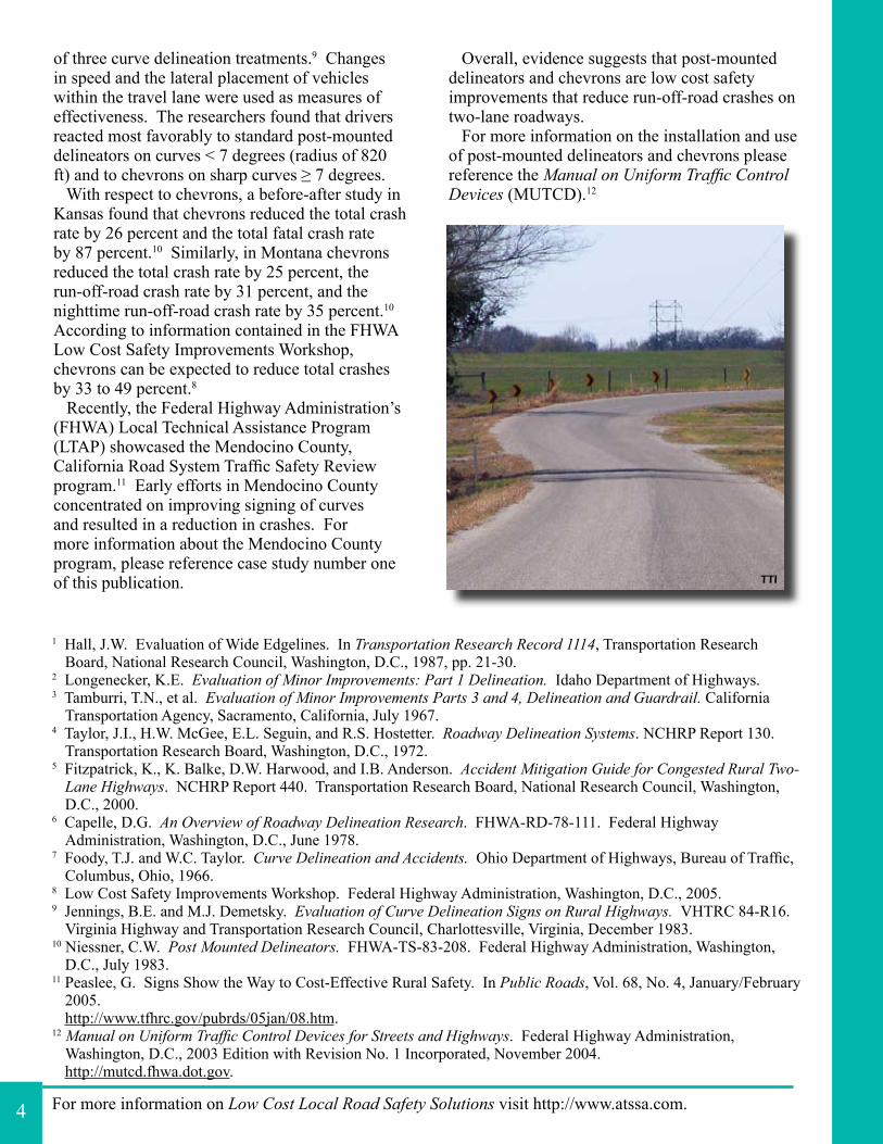
of three curve delineation treatments.9 Changes in speed and the lateral placement of vehicles within the travel lane were used as measures of effectiveness. The researchers found that drivers reacted most favorably to standard post-mounted delineators on curves < 7 degrees (radius of 820 ft) and to chevrons on sharp curves ≥ 7 degrees. With respect to chevrons, a before-after study in Kansas found that chevrons reduced the total crash rate by 26 percent and the total fatal crash rate by 87 percent.10 Similarly, in Montana chevrons reduced the total crash rate by 25 percent, the run-off-road crash rate by 31 percent, and the nighttime run-off-road crash rate by 35 percent.10 According to information contained in the FHWA Low Cost Safety Improvements Workshop, chevrons can be expected to reduce total crashes by 33 to 49 percent.8
Recently, the Federal Highway Administration’s (FHWA) Local Technical Assistance Program (LTAP) showcased the Mendocino County, California Road System Traffic Safety Review program.11 Early efforts in Mendocino County concentrated on improving signing of curves and resulted in a reduction in crashes. For more information about the Mendocino County program, please reference case study number one of this publication.
Overall, evidence suggests that post-mounted delineators and chevrons are low cost safety improvements that reduce run-off-road crashes on two-lane roadways. For more information on the installation and use of post-mounted delineators and chevrons please reference the Manual on Uniform Traffic Control Devices (MUTCD).12
1 Hall, J.W. Evaluation of Wide Edgelines. In Transportation Research Record 1114, Transportation Research Board, National Research Council, Washington, D.C., 1987, pp. 21-30.
2 Longenecker, K.E. Evaluation of Minor Improvements: Part 1 Delineation. Idaho Department of Highways.3 Tamburri, T.N., et al. Evaluation of Minor Improvements Parts 3 and 4, Delineation and Guardrail. California
Transportation Agency, Sacramento, California, July 1967.4 Taylor, J.I., H.W. McGee, E.L. Seguin, and R.S. Hostetter. Roadway Delineation Systems. NCHRP Report 130.
Transportation Research Board, Washington, D.C., 1972.5 Fitzpatrick, K., K. Balke, D.W. Harwood, and I.B. Anderson. Accident Mitigation Guide for Congested Rural Two-
Lane Highways. NCHRP Report 440. Transportation Research Board, National Research Council, Washington, D.C., 2000.
6 Capelle, D.G. An Overview of Roadway Delineation Research. FHWA-RD-78-111. Federal Highway Administration, Washington, D.C., June 1978.
7 Foody, T.J. and W.C. Taylor. Curve Delineation and Accidents. Ohio Department of Highways, Bureau of Traffic, Columbus, Ohio, 1966.
8 Low Cost Safety Improvements Workshop. Federal Highway Administration, Washington, D.C., 2005. 9 Jennings, B.E. and M.J. Demetsky. Evaluation of Curve Delineation Signs on Rural Highways. VHTRC 84-R16.
Virginia Highway and Transportation Research Council, Charlottesville, Virginia, December 1983.10 Niessner, C.W. Post Mounted Delineators. FHWA-TS-83-208. Federal Highway Administration, Washington,
D.C., July 1983.11 Peaslee, G. Signs Show the Way to Cost-Effective Rural Safety. In Public Roads, Vol. 68, No. 4, January/February
2005.http://www.tfhrc.gov/pubrds/05jan/08.htm.
12 Manual on Uniform Traffic Control Devices for Streets and Highways. Federal Highway Administration, Washington, D.C., 2003 Edition with Revision No. 1 Incorporated, November 2004.http://mutcd.fhwa.dot.gov.
4
TTI
LOW COST LOCAL ROADSAFETY SOLUTIONS
Volume 1 No. 3
In-Street Pedestrian Crossing SignsIncrease Driver Yielding Compliance
Warning signs and pavement markings used at pedestrian crossings can take many shapes and forms. Some of these traffic control devices are used to warn drivers to watch out for pedestrians. Even though drivers may receive the warning many of them consider yielding or stopping for pedestrians as a courtesy. However, in many states, it is the law. In-street pedestrian crossing signs are regulatory signs placed in the street (on edge lines, centerlines, or in medians) to remind drivers of their legal obligation with respect to pedestrians at unsignalized pedestrian crossings.1 These signs are easily implemented and may be removed for snow removal or other maintenance purposes. Typically, these signs are viewed as an appropriate treatment for lower speed roadways (≤ 30 mph) and cost $200 to $300 per sign (includes labor).2 Interest concerning in-street pedestrian crossing signs is growing, especially since these signs were added to the 2003 Edition of the Manual on Uniform Traffic Control Devices (MUTCD).1 Cities in several states including Iowa, Minnesota, New Hampshire, New York State, Wisconsin, Washington State, and the District of Columbia have deployed in-street pedestrian crossing signs as a low-cost safety improvement. Some of the first applications of in-
street pedestrian crossing signs were in New York State. In 1996, the New York State Department of Transportation developed a pedestrian safety cone that
could be placed in the middle of a crosswalk.3,4 This device consisted of a traffic cone fitted with an orange retroreflective “jacket” bearing the sign STATE LAW-YIELD TO PEDESTRIANS IN YOUR HALF OF ROAD. In the late 1990s, the Highway Safety Research Center (HSRC) evaluated the effectiveness of the New York State device at six locations in New
York State and one location in Portland, Oregon.3,4 All of the sites had a speed limit ≤ 30 mph and the average daily traffic (ADT) ranged from 7200 to 15,500 vehicles per day (vpd). Six of the sites were two-lane roadways (one had a two-way left-turn lane) and one site was a four-lane roadway. Combining data from all seven sites, in the before period drivers yielded to 70 percent of the pedestrians. After the installation of the pedestrian safety cone, drivers yielded to 81 percent of the pedestrians (a 16 percent increase). In the summer of 2002, the Center for Transportation Research and Education at Iowa State University completed a small-scale assessment of in-street pedestrian crossing signs in Cedar Rapids, Iowa.5 The signs were installed on a four-lane major arterial with a continuous left-turn lane.
SIG
NS
The use of in-street pedestrian
crossing signs increases driver yielding compliance at unsignalized pedestrian crossings by 5 to 20% resulting in driver yielding rates ranging from 67 to 98%.
5
For more information on Low Cost Local Road Safety Solutions visit http://www.atssa.com.
1 Manual on Uniform Traffic Control Devices for Streets and Highways. Federal Highway Administration, Washington, D.C., 2003 Edition with Revision No. 1 Incorporated, November 2004.http://mutcd.fhwa.dot.gov.
2 Fitzpatrick, K., S. Turner, M. Brewer, P. Carlson, N. Lalani, B. Ullman, N. Trout, E.S. Park, D. Lord, and J. Whitacre. Improving Pedestrian Safety at Unsignalized Crossings. Draft Report Submitted to the Transit Cooperative Research Program/National Cooperative Highway Research Program, Transportation Research Board, National Research Council, Washington, D.C., Janaury 2006.
3 Huang, H., C. Zegeer, R. Nassi, and B. Fairfax. The Effects of Innovative Pedestrian Signs at Unsignalized Locations: A Tale of Three Treatments. FHWA-RD-00-098. Federal Highway Administration, Washington, D.C., August 2000.http://www.tfhrc.gov/safety/pedbike/pubs/00-098.pdf.
4 Huang, H., C. Zegeer, and R. Nassi. Effects of Innovative Pedestrian Signs at Unsignalized Locations: Three Treatments. In Transportation Research Record 1705, Transportation Research Board, National Research Council, Washington, D.C., 2000, pp. 43-52.http://www.enhancements.org/trb%5C1705-008.pdf.
5 Kannel, E., R.R. Souleyrette, and R. Tenges. In-Street Yield to Pedestrian Sign Applications in Cedar Rapids, Iowa. CTRE Project 02-115. Center for Transportation Research and Education, Iowa State University, Ames, Iowa, May 2003.http://www.ctre.iastate.edu/reports/pedyield.pdf.
6 Byszeski, S. City of Redmond In Street Pedestrian Crossing Sign Test. FHWA Experimentation #2-507(Ex) – In Street Pedestrian Crossing Signs Six Month Report. City of Redmond, Public Works/Transportation, Redmond, Washington, June 2003.
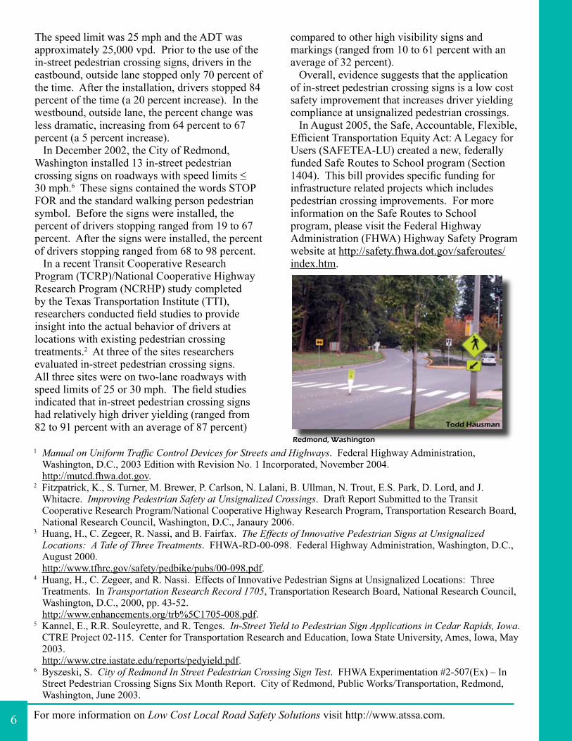
The speed limit was 25 mph and the ADT was approximately 25,000 vpd. Prior to the use of the in-street pedestrian crossing signs, drivers in the eastbound, outside lane stopped only 70 percent of the time. After the installation, drivers stopped 84 percent of the time (a 20 percent increase). In the westbound, outside lane, the percent change was less dramatic, increasing from 64 percent to 67 percent (a 5 percent increase). In December 2002, the City of Redmond, Washington installed 13 in-street pedestrian crossing signs on roadways with speed limits ≤ 30 mph.6 These signs contained the words STOP FOR and the standard walking person pedestrian symbol. Before the signs were installed, the percent of drivers stopping ranged from 19 to 67 percent. After the signs were installed, the percent of drivers stopping ranged from 68 to 98 percent. In a recent Transit Cooperative Research Program (TCRP)/National Cooperative Highway Research Program (NCRHP) study completed by the Texas Transportation Institute (TTI), researchers conducted field studies to provide insight into the actual behavior of drivers at locations with existing pedestrian crossing treatments.2 At three of the sites researchers evaluated in-street pedestrian crossing signs. All three sites were on two-lane roadways with speed limits of 25 or 30 mph. The field studies indicated that in-street pedestrian crossing signs had relatively high driver yielding (ranged from 82 to 91 percent with an average of 87 percent)
compared to other high visibility signs and markings (ranged from 10 to 61 percent with an average of 32 percent). Overall, evidence suggests that the application of in-street pedestrian crossing signs is a low cost safety improvement that increases driver yielding compliance at unsignalized pedestrian crossings. In August 2005, the Safe, Accountable, Flexible, Efficient Transportation Equity Act: A Legacy for Users (SAFETEA-LU) created a new, federally funded Safe Routes to School program (Section 1404). This bill provides specific funding for infrastructure related projects which includes pedestrian crossing improvements. For more information on the Safe Routes to School program, please visit the Federal Highway Administration (FHWA) Highway Safety Program website at http://safety.fhwa.dot.gov/saferoutes/index.htm.
6
Redmond, Washington
Todd Hausman
LOW COST LOCAL ROADSAFETY SOLUTIONS
Volume 1 No. 4
The use of a rear-facing flashing
beacon on a school speed limit sign assembly increases driver compliance with the school zone speed limit by 9 to 35%.
SIG
NS
Rear-Facing Flashing Beacons on School Speed Limit Signs Have a Positive Effect on Speeds
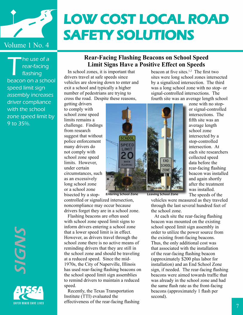
In school zones, it is important that drivers travel at safe speeds since vehicles are slowing down to enter and exit a school and typically a higher number of pedestrians are trying to cross the road. Despite these reasons, getting drivers to comply with school zone speed limits remains a challenge. Findings from research suggest that without police enforcement many drivers do not comply with school zone speed limits. However, under certain circumstances, such as an excessively long school zone or a school zone bisected by a stop-controlled or signalized intersection, noncompliance may occur because drivers forget they are in a school zone. Flashing beacons are often used with school zone speed limit signs to inform drivers entering a school zone that a lower speed limit is in effect. However, as drivers travel through the school zone there is no active means of reminding drivers that they are still in the school zone and should be traveling at a reduced speed. Since the mid-1970s, the City of Naperville, Illinois has used rear-facing flashing beacons on the school speed limit sign assemblies to remind drivers to maintain a reduced speed. Recently, the Texas Transportation Institute (TTI) evaluated the effectiveness of the rear-facing flashing
beacon at five sites.1,2 The first two sites were long school zones intersected by a signalized intersection. The third was a long school zone with no stop- or signal-controlled intersections. The fourth site was an average length school
zone with no stop-or signal-controlled intersections. The fifth site was an average length school zone intersected by a stop-controlled intersection. At each site researchers collected speed data before the rear-facing flashing beacon was installed and again shortly after the treatment was installed. The speeds of the
vehicles were measured as they traveled through the last several hundred feet of the school zone. At each site the rear-facing flashing beacon was mounted on the existing school speed limit sign assembly in order to utilize the power source from the existing front-facing beacons. Thus, the only additional cost was that associated with the installation of the rear-facing flashing beacon (approximately $200 plus labor for installation) and an End School Zone sign, if needed. The rear-facing flashing beacons were aimed towards traffic that was already in the school zone and had the same flash rate as the front-facing beacons (approximately 1 flash per second).
7
Entering School Zone Leaving School Zone
TTI
For more information on Low Cost Local Road Safety Solutions visit http://www.atssa.com.
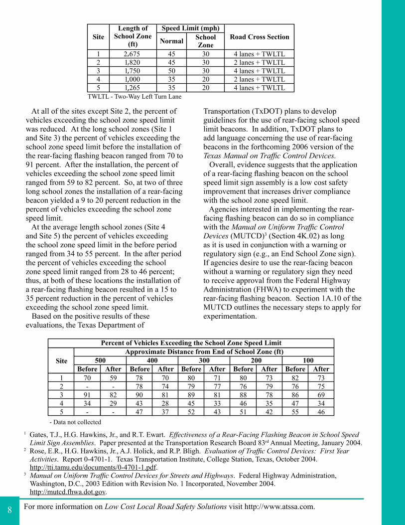
At all of the sites except Site 2, the percent of vehicles exceeding the school zone speed limit was reduced. At the long school zones (Site 1 and Site 3) the percent of vehicles exceeding the school zone speed limit before the installation of the rear-facing flashing beacon ranged from 70 to 91 percent. After the installation, the percent of vehicles exceeding the school zone speed limit ranged from 59 to 82 percent. So, at two of three long school zones the installation of a rear-facing beacon yielded a 9 to 20 percent reduction in the percent of vehicles exceeding the school zone speed limit. At the average length school zones (Site 4 and Site 5) the percent of vehicles exceeding the school zone speed limit in the before period ranged from 34 to 55 percent. In the after period the percent of vehicles exceeding the school zone speed limit ranged from 28 to 46 percent; thus, at both of these locations the installation of a rear-facing flashing beacon resulted in a 15 to 35 percent reduction in the percent of vehicles exceeding the school zone speed limit. Based on the positive results of these evaluations, the Texas Department of
Transportation (TxDOT) plans to develop guidelines for the use of rear-facing school speed limit beacons. In addition, TxDOT plans to add language concerning the use of rear-facing beacons in the forthcoming 2006 version of the Texas Manual on Traffic Control Devices. Overall, evidence suggests that the application of a rear-facing flashing beacon on the school speed limit sign assembly is a low cost safety improvement that increases driver compliance with the school zone speed limit. Agencies interested in implementing the rear-facing flashing beacon can do so in compliance with the Manual on Uniform Traffic Control Devices (MUTCD)3 (Section 4K.02) as long as it is used in conjunction with a warning or regulatory sign (e.g., an End School Zone sign). If agencies desire to use the rear-facing beacon without a warning or regulatory sign they need to receive approval from the Federal Highway Administration (FHWA) to experiment with the rear-facing flashing beacon. Section 1A.10 of the MUTCD outlines the necessary steps to apply for experimentation.
1 Gates, T.J., H.G. Hawkins, Jr., and R.T. Ewart. Effectiveness of a Rear-Facing Flashing Beacon in School Speed Limit Sign Assemblies. Paper presented at the Transportation Research Board 83rd Annual Meeting, January 2004.
2 Rose, E.R., H.G. Hawkins, Jr., A.J. Holick, and R.P. Bligh. Evaluation of Traffic Control Devices: First Year Activities. Report 0-4701-1. Texas Transportation Institute, College Station, Texas, October 2004.http://tti.tamu.edu/documents/0-4701-1.pdf.
3 Manual on Uniform Traffic Control Devices for Streets and Highways. Federal Highway Administration, Washington, D.C., 2003 Edition with Revision No. 1 Incorporated, November 2004.http://mutcd.fhwa.dot.gov.
8
,,
,,,
LOW COST LOCAL ROADSAFETY SOLUTIONS
Volume 1 No. 5
Studies show that speed displays
can significantly improve speed limit compliance by reducing vehicle speeds by approximately 10 mph.
SIG
NS
Speed Displays Reduce Traffic Speedsand Increase Speed Limit Compliance
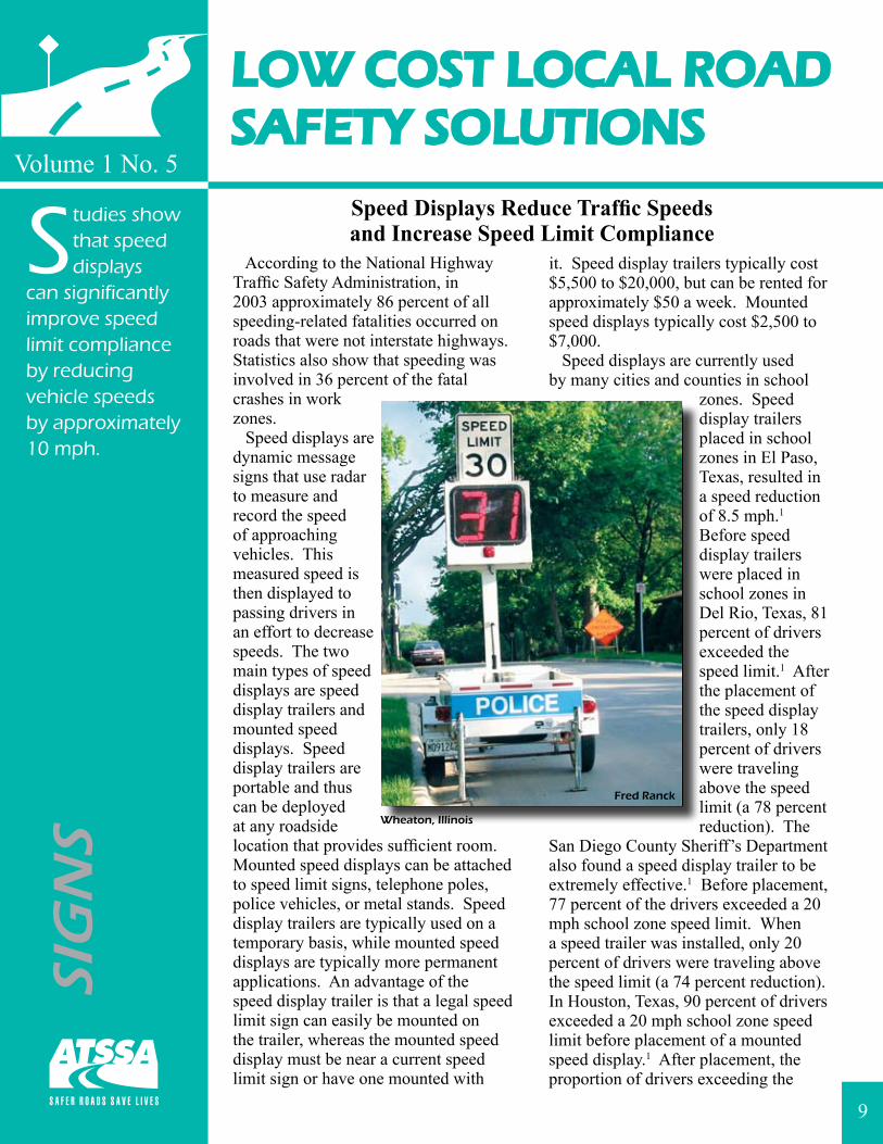
According to the National Highway Traffic Safety Administration, in 2003 approximately 86 percent of all speeding-related fatalities occurred on roads that were not interstate highways. Statistics also show that speeding was involved in 36 percent of the fatal crashes in work zones. Speed displays are dynamic message signs that use radar to measure and record the speed of approaching vehicles. This measured speed is then displayed to passing drivers in an effort to decrease speeds. The two main types of speed displays are speed display trailers and mounted speed displays. Speed display trailers are portable and thus can be deployed at any roadside location that provides sufficient room. Mounted speed displays can be attached to speed limit signs, telephone poles, police vehicles, or metal stands. Speed display trailers are typically used on a temporary basis, while mounted speed displays are typically more permanent applications. An advantage of the speed display trailer is that a legal speed limit sign can easily be mounted on the trailer, whereas the mounted speed display must be near a current speed limit sign or have one mounted with
it. Speed display trailers typically cost $5,500 to $20,000, but can be rented for approximately $50 a week. Mounted speed displays typically cost $2,500 to $7,000. Speed displays are currently used by many cities and counties in school
zones. Speed display trailers placed in school zones in El Paso, Texas, resulted in a speed reduction of 8.5 mph.1 Before speed display trailers were placed in school zones in Del Rio, Texas, 81 percent of drivers exceeded the speed limit.1 After the placement of the speed display trailers, only 18 percent of drivers were traveling above the speed limit (a 78 percent reduction). The
San Diego County Sheriff’s Department also found a speed display trailer to be extremely effective.1 Before placement, 77 percent of the drivers exceeded a 20 mph school zone speed limit. When a speed trailer was installed, only 20 percent of drivers were traveling above the speed limit (a 74 percent reduction). In Houston, Texas, 90 percent of drivers exceeded a 20 mph school zone speed limit before placement of a mounted speed display.1 After placement, the proportion of drivers exceeding the
9
Fred Ranck
Wheaton, Illinois
For more information on Low Cost Local Road Safety Solutions visit http://www.atssa.com.
1 Fors, C. Controlling Community Speeds with Radar Displays. In Police and Security News, Vol. 18, No. 5, 2002. http://www.policeandsecuritynews.com/septoct02/contollingSpeed.htm.
2 Bloch, S.A. A Comparative Study of the Speed Reduction Effects of Photo-Radar and Speed Display Boards. Paper presented at the Transportation Research Board 78th Annual Meeting, Washington, D.C., January 1998.
3 Rose, E.R. and G.L. Ullman. Evaluation of Dynamic Speed Display Signs (DSDS). Report 0-4475-1. Texas Transportation Institute, College Station, Texas, September 2003.http://tti.tamu.edu/documents/0-4475-1.pdf.
4 Fontaine, M.D., P.J. Carlson, and H.G. Hawkins, Jr. Evaluation of Traffic Control Devices for Rural High-Speed Maintenance Work Zones: Second Year Activities and Final Recommendations. Report 0-1879-2. Texas Transportation Institute, College Station, Texas, October 2000. http://tti.tamu.edu/documents/1879-2.pdf.
speed limit decreased to 15 percent (an 83 percent reduction). The City of Phoenix found that a speed display in a school zone with a 15 mph speed limit substantially reduced the 85th percentile speed from approximately 48 mph to approximately 15 mph (a 33 mph reduction).1 At a second site, the 85th percentile speed was reduced from 32 mph to 25 mph (a 7 mph reduction). A study in Santa Barbara, California found that speeds alongside the speed display trailer were reduced
by 10 percent and by 7 percent downstream for a distance up to 0.5 mile.2
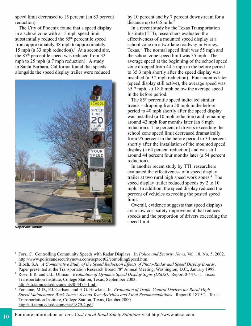
In a recent study by the Texas Transportation Institute (TTI), researchers evaluated the effectiveness of a mounted speed display at a school zone on a two-lane roadway in Forney, Texas.3 The normal speed limit was 55 mph and the school zone speed limit was 35 mph. The average speed at the beginning of the school speed zone dropped from 44.5 mph in the before period to 35.3 mph shortly after the speed display was installed (a 9.2 mph reduction). Four months later (speed display still active), the average speed was 35.7 mph, still 8.8 mph below the average speed in the before period. The 85th percentile speed indicated similar trends – dropping from 50 mph in the before period to 40 mph shortly after the speed display was installed (a 10 mph reduction) and remaining around 42 mph four months later (an 8 mph reduction). The percent of drivers exceeding the school zone speed limit decreased dramatically from 95 percent in the before period to 34 percent shortly after the installation of the mounted speed display (a 64 percent reduction) and was still around 44 percent four months later (a 54 percent reduction). In another recent study by TTI, researchers evaluated the effectiveness of a speed display trailer at two rural high speed work zones.4 The speed display trailer reduced speeds by 2 to 10 mph. In addition, the speed display reduced the percent of vehicles exceeding the posted speed limit. Overall, evidence suggests that speed displays are a low cost safety improvement that reduces speeds and the proportion of drivers exceeding the speed limit.
10
Fred Ranck
Naperville, Illinois
LOW COST LOCAL ROADSAFETY SOLUTIONS
Volume 1 No. 6
Crash studies show that edge
lines on two-lane roadways typically reduce crash frequency, especially in horizontal curves.
PA
VE
ME
NT
TR
EA
TM
EN
TS
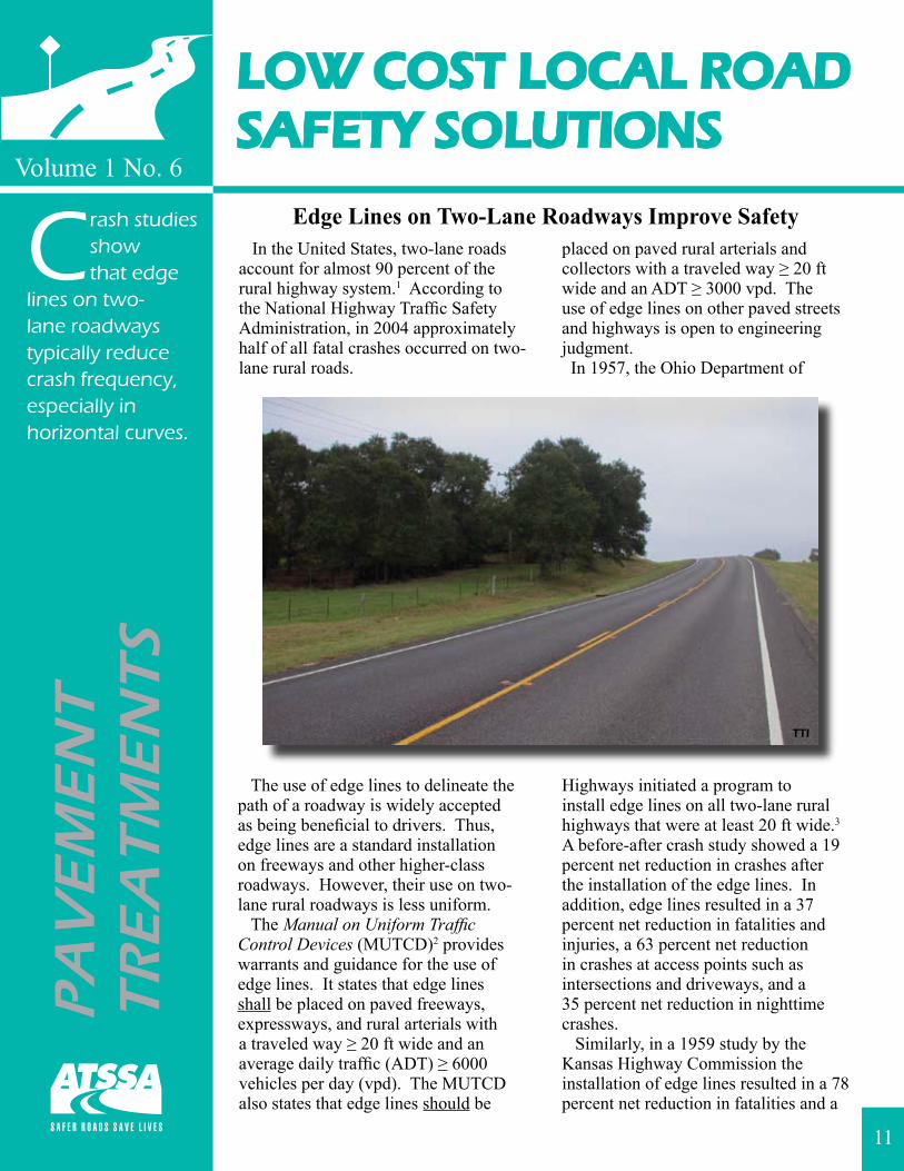
Edge Lines on Two-Lane Roadways Improve Safety In the United States, two-lane roads account for almost 90 percent of the rural highway system.1 According to the National Highway Traffic Safety Administration, in 2004 approximately half of all fatal crashes occurred on two-lane rural roads.
The use of edge lines to delineate the path of a roadway is widely accepted as being beneficial to drivers. Thus, edge lines are a standard installation on freeways and other higher-class roadways. However, their use on two-lane rural roadways is less uniform. The Manual on Uniform Traffic Control Devices (MUTCD)2 provides warrants and guidance for the use of edge lines. It states that edge lines shall be placed on paved freeways, expressways, and rural arterials with a traveled way ≥ 20 ft wide and an average daily traffic (ADT) ≥ 6000 vehicles per day (vpd). The MUTCD also states that edge lines should be
placed on paved rural arterials and collectors with a traveled way ≥ 20 ft wide and an ADT ≥ 3000 vpd. The use of edge lines on other paved streets and highways is open to engineering judgment. In 1957, the Ohio Department of
Highways initiated a program to install edge lines on all two-lane rural highways that were at least 20 ft wide.3 A before-after crash study showed a 19 percent net reduction in crashes after the installation of the edge lines. In addition, edge lines resulted in a 37 percent net reduction in fatalities and injuries, a 63 percent net reduction in crashes at access points such as intersections and driveways, and a 35 percent net reduction in nighttime crashes. Similarly, in a 1959 study by the Kansas Highway Commission the installation of edge lines resulted in a 78 percent net reduction in fatalities and a
11
TTI
For more information on Low Cost Local Road Safety Solutions visit http://www.atssa.com.
1 Table HM-35 Federal-Aid Highway Length – 2003 Miles by Traffic Lanes and Access Control. Highway Statistics 2003. Federal Highway Administration, Washington, D.C., 2003.http://www.fhwa.dot.gov/ohim/hs00/hm35.htm.
2 Manual on Uniform Traffic Control Devices for Streets and Highways. Federal Highway Administration, Washington, D.C., 2003 Edition with Revision No. 1 Incorporated, November 2004.http://mutcd.fhwa.dot.gov.
3 Musick, J.V. Effect of Pavement Edge Marking on Two-Lane Rural State Highways in Ohio. In Highway Research Board Bulletin 266, Highway Research Board, National Research Council, Washington, D.C., 1962, pp. 1-7.
4 Basile, A.J. Effect of Pavement Edge Markings on Traffic Accidents in Kansas. In Highway Research Board Bulletin 308, Highway Research Board, National Research Council, Washington, D.C., 1962, pp. 80-86.
5 Tsyganov, A., R.B. Machemehl, and N.M. Warrenchuk. Safety Impact of Edge Lines on Rural Two-Lane Highways. Center for Transportation Research, The University of Texas, Austin, Texas, September 2005. http://www.utexas.edu/research/ctr/pdf_reports/0_5090_1.pdf.
6 Miller, T.R. Benefit-Cost Analysis of Lane Marking. In Transportation Research Record 1334, Transportation Research Board, National Research Council, Washington, D.C., 1992, pp. 38-45.
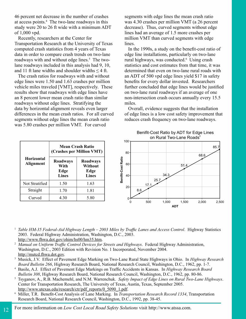
46 percent net decrease in the number of crashes at access points.4 The two-lane roadways in this study were 20 to 26 ft wide with a minimum ADT of 1,000 vpd. Recently, researchers at the Center for Transportation Research at the University of Texas computed crash statistics from 4 years of Texas data in order to compare crash trends on two-lane roadways with and without edge lines.5 The two-lane roadways included in this analysis had 9, 10, and 11 ft lane widths and shoulder widths ≤ 4 ft. The crash ratios for roadways with and without edge lines were 1.50 and 1.63 crashes per million vehicle miles traveled [VMT], respectively. These results show that roadways with edge lines have an 8 percent lower mean crash ratio than similar roadways without edge lines. Stratifying the data by horizontal alignment reveals even larger differences in the mean crash ratios. For all curved segments without edge lines the mean crash ratio was 5.80 crashes per million VMT. For curved
segments with edge lines the mean crash ratio was 4.30 crashes per million VMT (a 26 percent decrease). Thus, curved segments without edge lines had an average of 1.5 more crashes per million VMT than curved segments with edge lines. In the 1990s, a study on the benefit-cost ratio of edge line installations, particularly on two-lane rural highways, was conducted.6 Using crash statistics and cost estimates from that time, it was determined that even on two-lane rural roads with an ADT of 500 vpd edge lines yield $17 in safety benefits for every dollar invested. Researchers further concluded that edge lines would be justified on two-lane rural roadways if an average of one non-intersection crash occurs annually every 15.5 miles. Overall, evidence suggests that the installation of edge lines is a low cost safety improvement that reduces crash frequency on two-lane roadways.
12
LOW COST LOCAL ROADSAFETY SOLUTIONS
Volume 1 No. 7
The use of wider pavement
markings results in crash reductions and improves visibility, lane positioning, and driver comfort.
PA
VE
ME
NT
TR
EA
TM
EN
TS
Wider Longitudinal Pavement Markings Improve Safety According to the National Highway Traffic Safety Administration, in 1999 there were 8,091 (24 percent) single vehicle run-off-road crashes on two-lane roadways. One safety strategy recommended to address run-off-road crashes is the use of wider longitudinal pavement markings.1
The Manual on Uniform Traffic Control Devices (MUTCD)2 specifies the normal width of a longitudinal line to be 4 to 6 inches wide. Even though the MUTCD standards for pavement
marking width have remained essentially the same since 1971, historically, most state transportation agencies have used 4-inch lines as their standard. Wider markings (in some cases up to 12 inches) are used extensively in Europe and over the past two decades an increasing number of agencies have begun to use wider markings as tools to enhance roadway safety.3 Herein, the term “wider markings” refers to longitudinal pavement markings (centerline, lane line, or edge line) greater than 4 inches in width. In 2001, researchers at the Texas Transportation Institute (TTI) administered a survey to transportation agencies in the United States and
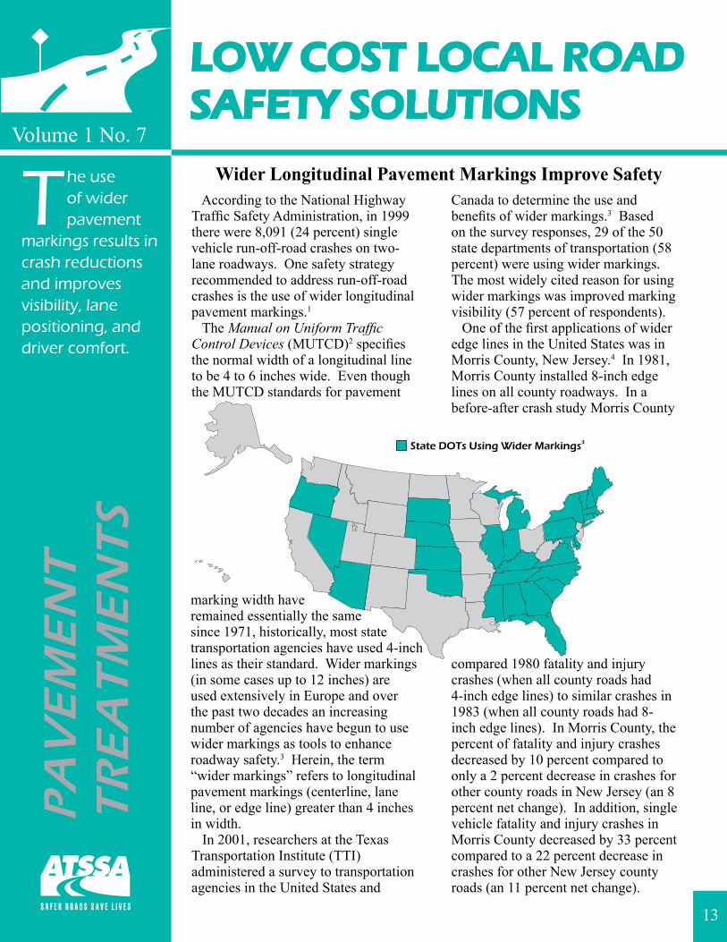
Canada to determine the use and benefits of wider markings.3 Based on the survey responses, 29 of the 50 state departments of transportation (58 percent) were using wider markings. The most widely cited reason for using wider markings was improved marking visibility (57 percent of respondents). One of the first applications of wider edge lines in the United States was in Morris County, New Jersey.4 In 1981, Morris County installed 8-inch edge lines on all county roadways. In a before-after crash study Morris County
compared 1980 fatality and injury crashes (when all county roads had 4-inch edge lines) to similar crashes in 1983 (when all county roads had 8-inch edge lines). In Morris County, the percent of fatality and injury crashes decreased by 10 percent compared to only a 2 percent decrease in crashes for other county roads in New Jersey (an 8 percent net change). In addition, single vehicle fatality and injury crashes in Morris County decreased by 33 percent compared to a 22 percent decrease in crashes for other New Jersey county roads (an 11 percent net change).
13
For more information on Low Cost Local Road Safety Solutions visit http://www.atssa.com.
A 1988 study by the New York State Department of Transportation indicated that sections of curving two-lane rural roads with new 8-inch edge lines resulted in higher crash reductions than similar sections with new 4-inch edge lines.1 In particular, the study found greater safety effects for total crashes (a 10 percent decrease for wider edge lines versus a 5 percent increase for standard edge lines), for injury crashes (a 15 percent decrease versus a 10 percent decrease, respectively), and for fixed-object crashes (a 33 percent decrease versus a 17 percent decrease, respectively). In a 1989 Federal Highway Administration (FHWA) study, researchers found that for rural roadways 24 ft wide, with less than 6 ft shoulders, and average daily traffic (ADT) volumes between 2,000 and 5,000 vehicle per day (vpd), those striped with 8-inch edge lines experienced a relative decrease in total crash rate, total crash frequency, and injury/fatal crash rate compared to those roadways striped with 4-inch edge lines.5 These findings were based on information provided by the Alabama Department of Transportation for nearly 300 miles of two-lane rural highways. Based on the research findings, the researchers recommended 8-inch edge lines on roadways with the following conditions: ADT between 2,000 and 5,000 vpd, pavement width equal to 24 ft with unpaved shoulders, and frequent rainfall. Historically, benefit-cost analyses have served as an engineering benchmark by which to compare roadway countermeasures; unfortunately to date conclusive benefit-cost data are not obtainable. In
the 1980s, a FHWA study did determine that an annual reduction of only eight edge line-related crashes for every 1,000 miles striped with 8-inch edge lines would allow for the wider lines to be cost-effective; however, many transportation agencies are turning to indirect safety measures to justify the use of wider markings.3,5 These indirect measures include: driver opinion surveys, visibility measures (e.g., detection distance), and surrogate safety measures (e.g., vehicle position). One of the most notable driver opinion surveys concerning wider markings was conducted in Florida.3 This survey showed that older drivers preferred wider markings. The decision to implement 6-inch markings statewide was due in part to the results of this survey. Two studies have found a significant increase in the average end detection distance between 4-inch and wider edge lines (6-inch and 8-inch) for younger drivers, as well as older drivers.6,7 A study in Massachusetts showed that 8-inch edge lines on curved highway segments results in fewer lane departures compared to 4-inch edge lines.5 Overall, evidence suggests that the installation of wider pavement markings is a low cost safety improvement that reduces crash frequency, improves end detection, improves lane positioning, benefits older drivers, and improves driver comfort.
1 Neuman, T.R., R. Pfefer, K.L. Slack, K.K. Hardy, F. Council, H. McGee, L. Prothe, and K. Eccles. Guidance for Implementation of the AASHTO Strategic Highway Safety Plan Volume 6: A Guide for Addressing Run-Off-Road Collisions. NCHRP Report 500. Transportation Research Board, Washington, D.C., 2003.http://gulliver.trb.org/publications/nchrp/nchrp_rpt_500v6.pdf.
2 Manual on Uniform Traffic Control Devices for Streets and Highways. Federal Highway Administration, Washington, D.C., 2003 Edition with Revision No. 1 Incorporated, November 2004. http://mutcd.fhwa.dot.gov.
3 Gates, T. J. and H.G. Hawkins. The Use of Wider Longitudinal Pavement Markings. Report 0024-1. Texas Transportation Institute, College Station, Texas, March 2002.http://tti.tamu.edu/documents/0024-1.pdf.
4 Wider Edgelines Cut Accident Rates. In Better Roads, April 1986, pp. 33-34.5 Hughes, W.E., H.W. McGee, S. Hussain, and J. Keegel. Field Evaluation of Edgeline Widths. FHWA-89-111.
Bellomo-McGee, Inc., Federal Highway Administration, Washington, D.C., 1989.6 Zwahlen, H.T. and T. Schnell. Visibility of New Pavement Markings at Night Under Low-Beam Illumination. In
Transportation Research Record 1495, Transportation Research Board, National Research Council, Washington, D.C., 1995.
7 Schnell, T. and P.J. Ohme. Evaluation of Various Strategies to Increase Pavement Marking Visibility of Older Drivers. Paper presented at the Transportation Research Board’s 81st Annual Meeting, January 2002.
14
LOW COST LOCAL ROADSAFETY SOLUTIONS
Volume 1 No. 8
Crash studies show that RPMs reduce
total crashes by 7 to 10% and reduce nighttime wet weather crashes by 24 to 33%.
Raised Pavement Markers Reduce Crasheson Two-Lane Roadways
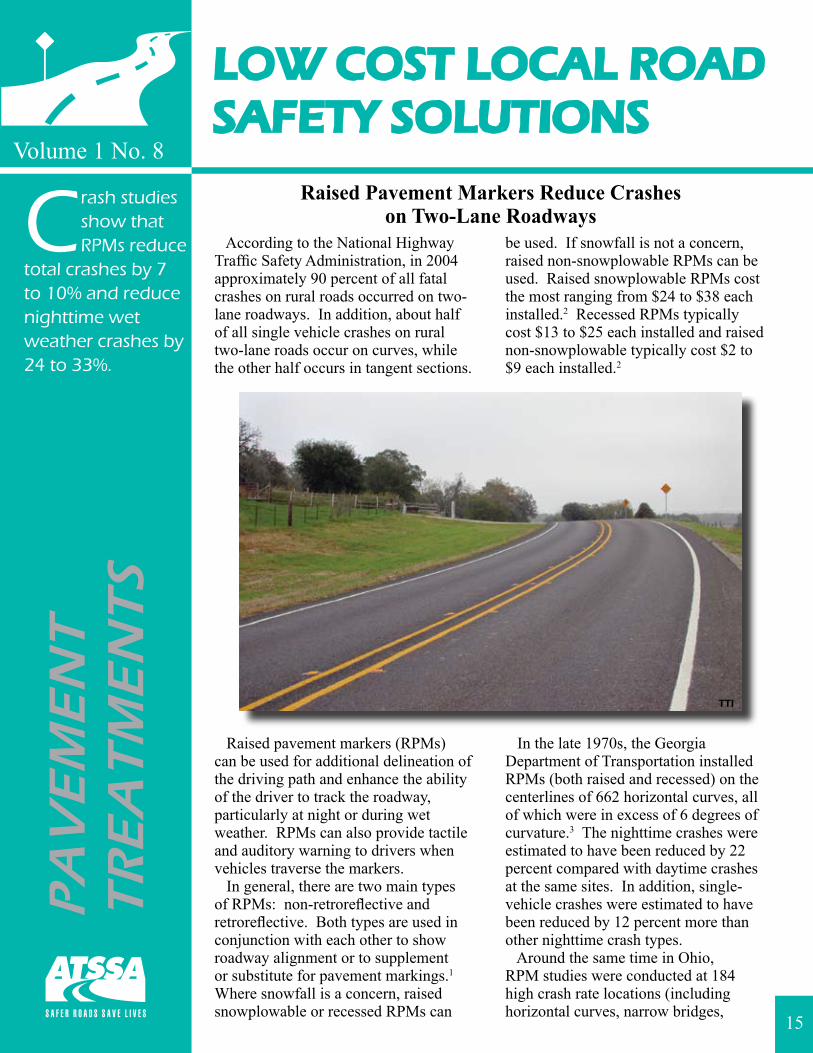
According to the National Highway Traffic Safety Administration, in 2004 approximately 90 percent of all fatal crashes on rural roads occurred on two-lane roadways. In addition, about half of all single vehicle crashes on rural two-lane roads occur on curves, while the other half occurs in tangent sections.
Raised pavement markers (RPMs) can be used for additional delineation of the driving path and enhance the ability of the driver to track the roadway, particularly at night or during wet weather. RPMs can also provide tactile and auditory warning to drivers when vehicles traverse the markers. In general, there are two main types of RPMs: non-retroreflective and retroreflective. Both types are used in conjunction with each other to show roadway alignment or to supplement or substitute for pavement markings.1 Where snowfall is a concern, raised snowplowable or recessed RPMs can
be used. If snowfall is not a concern, raised non-snowplowable RPMs can be used. Raised snowplowable RPMs cost the most ranging from $24 to $38 each installed.2 Recessed RPMs typically cost $13 to $25 each installed and raised non-snowplowable typically cost $2 to $9 each installed.2
In the late 1970s, the Georgia Department of Transportation installed RPMs (both raised and recessed) on the centerlines of 662 horizontal curves, all of which were in excess of 6 degrees of curvature.3 The nighttime crashes were estimated to have been reduced by 22 percent compared with daytime crashes at the same sites. In addition, single-vehicle crashes were estimated to have been reduced by 12 percent more than other nighttime crash types. Around the same time in Ohio, RPM studies were conducted at 184 high crash rate locations (including horizontal curves, narrow bridges,
PA
VE
ME
NT
TR
EA
TM
EN
TS
15
TTI
For more information on Low Cost Local Road Safety Solutions visit http://www.atssa.com.
1 Manual on Uniform Traffic Control Devices for Streets and Highways. Federal Highway Administration, Washington, D.C., 2003 Edition with Revision No. 1 Incorporated, November 2004.http://mutcd.fhwa.dot.gov.
2 Migletz, J. and J. Graham. Long-Term Pavement Marking Practices. NCHRP Synthesis 306. Transportation Research Board, Washington, D.C., 2002.http://trb.org/news/blurb_detail.asp?id=1119.
3 Wright, P.H., P.L. Zador, C.Y. Park, and R.S. Karpf. Effect of Pavement Markers on Nighttime Crashes in Georgia. Insurance Institute for Highway Safety, Washington, D.C., 1982.
4 Neuman, T.R., R. Pfefer, K.L. Slack, K.K. Hardy, F. Council, H. McGee, L. Prothe, and K. Eccles. Guidance for Implementation of the AASHTO Strategic Highway Safety Plan Volume 6: A Guide for Addressing Run-Off-Road Collisions. NCHRP Report 500. Transportation Research Board, Washington, D.C., 2003.http://gulliver.trb.org/publications/nchrp/nchrp_rpt_500v6.pdf.
5 Highway Safety Improvement Program-Annual Evaluation Report. New York State Department of Transportation, Albany, New York, 1989.
6 Raised Reflectorized Snowplowable Pavement Markers: A Report to the Governor. New York State Department of Transportation, Albany, New York, 1997.
7 Bahar, G., C. Mollett, B. Persaud, C. Lyon, A. Smiley, T. Smahel, and H. McGee. Safety Evaluation of Permanent Raised Pavement Markers. NCHRP Report 518. Transportation Research Board, Washington, D.C., 2004.http://gulliver.trb.org/publications/nchrp/nchrp_rpt_518.pdf.
stop approaches, and interchanges).4 Over 3,200 crashes at these locations were analyzed one year before and one year after installation. The results show a 9 percent reduction in crashes and a 15 percent decrease in injuries. RPMs were considered effective under all types of driving conditions, including nighttime conditions (a 5 percent reduction) and adverse weather conditions (a 6 percent reduction at the same time precipitation increased by 11 percent). Based on these results, the study concluded that for every dollar spent on RPMs there was a return of $6.50 in savings due to a crash reduction. In the late 1980s, RPMs were installed on approximately 230 miles of mainly two-lane roadways in New Jersey.4 Using data from two years before and one year after, there was a significant reduction in various types of nighttime crashes including total injury, head-on, and overturn crashes. The calculated benefit-cost ratios ranged from 15.49:1 to 25.51:1. In the late 1990s, the New York State Department of Transportation conducted a safety assessment of RPMs as part of a review of the department’s policy on RPM installation.5,6 The before-after study included 20 sites where RPMs had been installed selectively on unlit suburban and rural roadways with proportionately high numbers of nighttime crashes and nighttime wet weather crashes. The results show a 7 percent decrease in total crashes, a 26 percent decrease in nighttime crashes, and a 33 percent decrease in
nighttime wet weather crashes. In addition, there was a 23 percent reduction in all guidance related crashes (e.g., run-off-road, head-on, encroachment, and sideswipe) and a 39 percent reduction in nighttime guidance crashes. Recently, National Cooperative Highway Research Program (NCHRP) Project 5-17 was completed to quantify the safety effects of RPMs and to develop guidelines for their use.7 This study gathered data in six states (Illinois, Missouri, New Jersey, New York, Pennsylvania, and Wisconsin) to evaluate the safety performance of snowplowable RPMs at non-intersection locations along two-lane roadways, four-lane expressways, and four-lane freeways. For two-lane roadways, the New Jersey data showed a 20 percent decrease in head-on crashes after the nonselective implementation of RPMs. In addition, the New York data showed a 10 percent decrease in total crashes, a 13 percent decrease in nighttime crashes, a 20 percent decrease in wet weather crashes, and a 24 percent decrease in wet weather nighttime crashes after the selective implementation of RPMs on two-lane roadways. Overall, evidence suggests that the installation of RPMs is low cost safety improvement that reduces crashes, especially nighttime wet weather crashes, on two-lane roadways. For more information on the use of RPMs, please reference the Manual on Uniform Traffic Control Devices (MUTCD)1 and NCHRP Report 518.7
16
LOW COST LOCAL ROADSAFETY SOLUTIONS
Volume 1 No. 9
Shoulder and edge line rumble
strips on two-lane roadways reduce run-off-road crashes by 25% and yield estimated benefit-cost ratios ranging from 2 to 221.
Shoulder and Edge Line Rumble StripsReduce Run-Off-Road Crashes
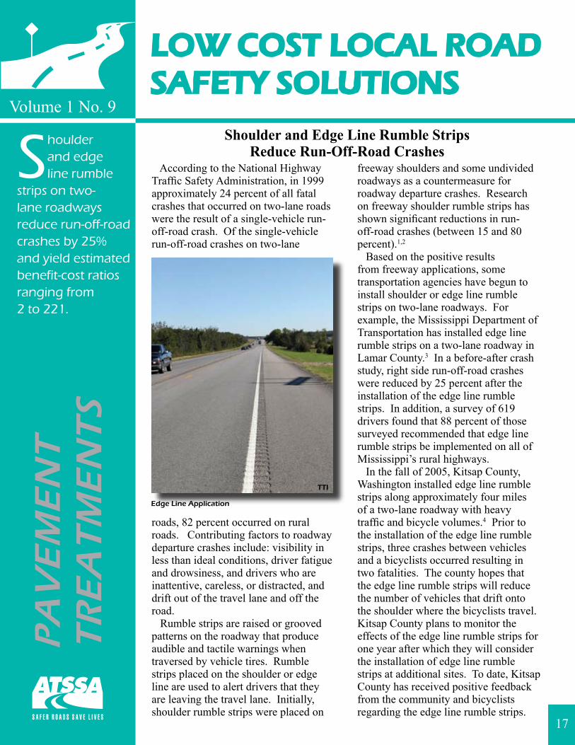
According to the National Highway Traffic Safety Administration, in 1999 approximately 24 percent of all fatal crashes that occurred on two-lane roads were the result of a single-vehicle run-off-road crash. Of the single-vehicle run-off-road crashes on two-lane
roads, 82 percent occurred on rural roads. Contributing factors to roadway departure crashes include: visibility in less than ideal conditions, driver fatigue and drowsiness, and drivers who are inattentive, careless, or distracted, and drift out of the travel lane and off the road. Rumble strips are raised or grooved patterns on the roadway that produce audible and tactile warnings when traversed by vehicle tires. Rumble strips placed on the shoulder or edge line are used to alert drivers that they are leaving the travel lane. Initially, shoulder rumble strips were placed on
freeway shoulders and some undivided roadways as a countermeasure for roadway departure crashes. Research on freeway shoulder rumble strips has shown significant reductions in run-off-road crashes (between 15 and 80 percent).1,2
Based on the positive results from freeway applications, some transportation agencies have begun to install shoulder or edge line rumble strips on two-lane roadways. For example, the Mississippi Department of Transportation has installed edge line rumble strips on a two-lane roadway in Lamar County.3 In a before-after crash study, right side run-off-road crashes were reduced by 25 percent after the installation of the edge line rumble strips. In addition, a survey of 619 drivers found that 88 percent of those surveyed recommended that edge line rumble strips be implemented on all of Mississippi’s rural highways. In the fall of 2005, Kitsap County, Washington installed edge line rumble strips along approximately four miles of a two-lane roadway with heavy traffic and bicycle volumes.4 Prior to the installation of the edge line rumble strips, three crashes between vehicles and a bicyclists occurred resulting in two fatalities. The county hopes that the edge line rumble strips will reduce the number of vehicles that drift onto the shoulder where the bicyclists travel. Kitsap County plans to monitor the effects of the edge line rumble strips for one year after which they will consider the installation of edge line rumble strips at additional sites. To date, Kitsap County has received positive feedback from the community and bicyclists regarding the edge line rumble strips.
PA
VE
ME
NT
TR
EA
TM
EN
TS
17
TTI
Edge Line Application
For more information on Low Cost Local Road Safety Solutions visit http://www.atssa.com.
1 Federal Highway Administration Highway Safety Program Rumble Strip Website, Accessed January 2006. http://safety.fhwa.dot.gov/roadway_dept/rumble/effectiveness.htm.
2 Morena, D.A. Rumbling Toward Safety. In Public Roads, Vol. 67, No. 2, September/October 2003. http://www.tfhrc.gov/pubrds/03sep/06.htm.
3 Willis, J. and W. Dean. Mississippi’s Rumble Stripe Experience. Presentation at the Transportation Research Board’s 83rd Annual Meeting, January 2004.http://tcd.tamu.edu/documents/rumble/rumble1.htm.
4 Information provided by Bill Zupancic of Kitsap County, Washington.http://www.kitsapgov.com/pw/pilot_program.htm.
5 Carlson, P.J. and J.D. Miles. Traffic Operational Impacts of Transverse, Centerline, and Edgeline Rumble Strips. Report 0-4472-2. Texas Transportation Institute, College Station, Texas, September 2003.http://tti.tamu.edu/documents/0-4472-2.pdf.
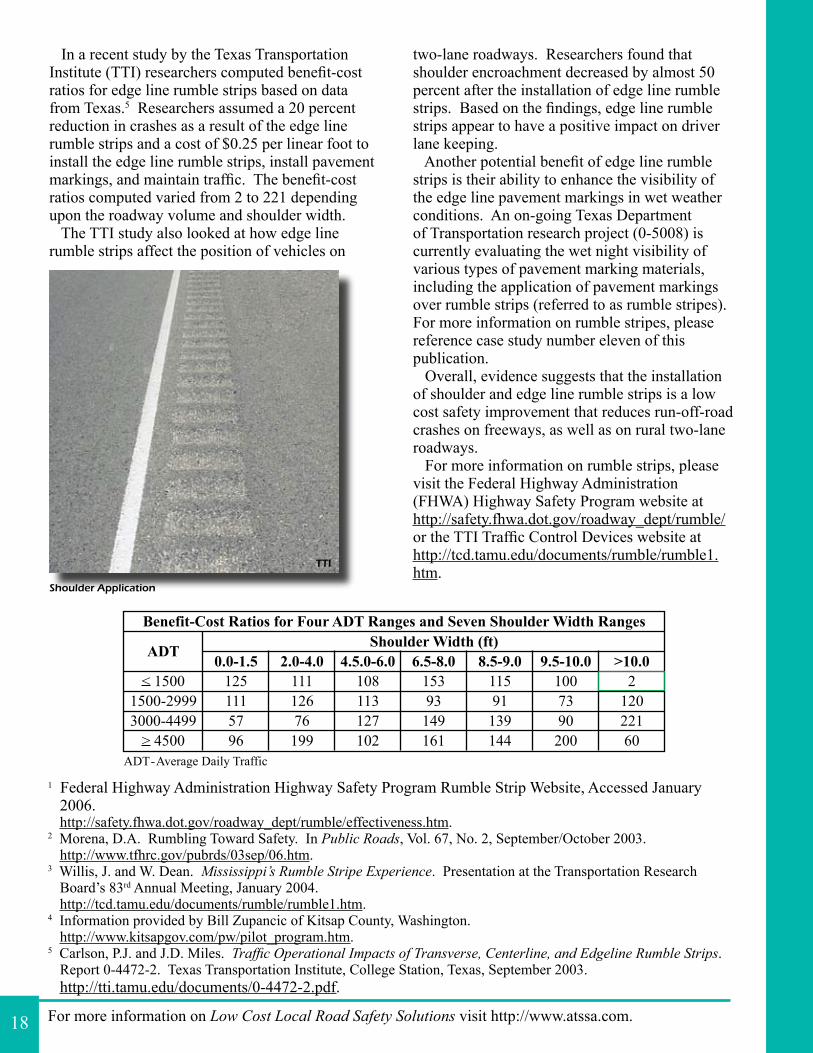
In a recent study by the Texas Transportation Institute (TTI) researchers computed benefit-cost ratios for edge line rumble strips based on data from Texas.5 Researchers assumed a 20 percent reduction in crashes as a result of the edge line rumble strips and a cost of $0.25 per linear foot to install the edge line rumble strips, install pavement markings, and maintain traffic. The benefit-cost ratios computed varied from 2 to 221 depending upon the roadway volume and shoulder width. The TTI study also looked at how edge line rumble strips affect the position of vehicles on
two-lane roadways. Researchers found that shoulder encroachment decreased by almost 50 percent after the installation of edge line rumble strips. Based on the findings, edge line rumble strips appear to have a positive impact on driver lane keeping. Another potential benefit of edge line rumble strips is their ability to enhance the visibility of the edge line pavement markings in wet weather conditions. An on-going Texas Department of Transportation research project (0-5008) is currently evaluating the wet night visibility of various types of pavement marking materials, including the application of pavement markings over rumble strips (referred to as rumble stripes). For more information on rumble stripes, please reference case study number eleven of this publication. Overall, evidence suggests that the installation of shoulder and edge line rumble strips is a low cost safety improvement that reduces run-off-road crashes on freeways, as well as on rural two-lane roadways. For more information on rumble strips, please visit the Federal Highway Administration (FHWA) Highway Safety Program website at http://safety.fhwa.dot.gov/roadway_dept/rumble/ or the TTI Traffic Control Devices website at http://tcd.tamu.edu/documents/rumble/rumble1.htm.
18
Shoulder Application
TTI
LOW COST LOCAL ROADSAFETY SOLUTIONS
Volume 1 No. 10
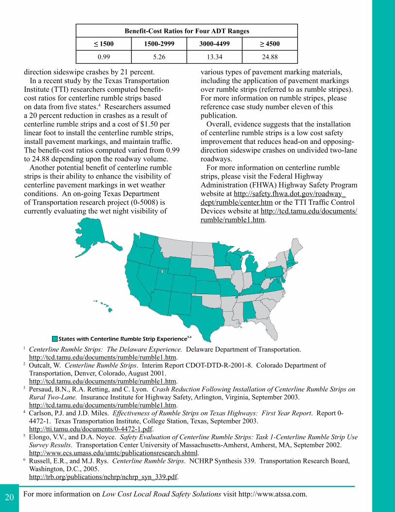
Crash studies show that centerline
rumble strips typically reduce head-on and opposing-direction sideswipe crashes by 20 to 25% and yield benefit-cost ratios ranging from 0.99 to 24.88.
Centerline Rumble Strips Reduce Head-Onand Sideswipe Crashes
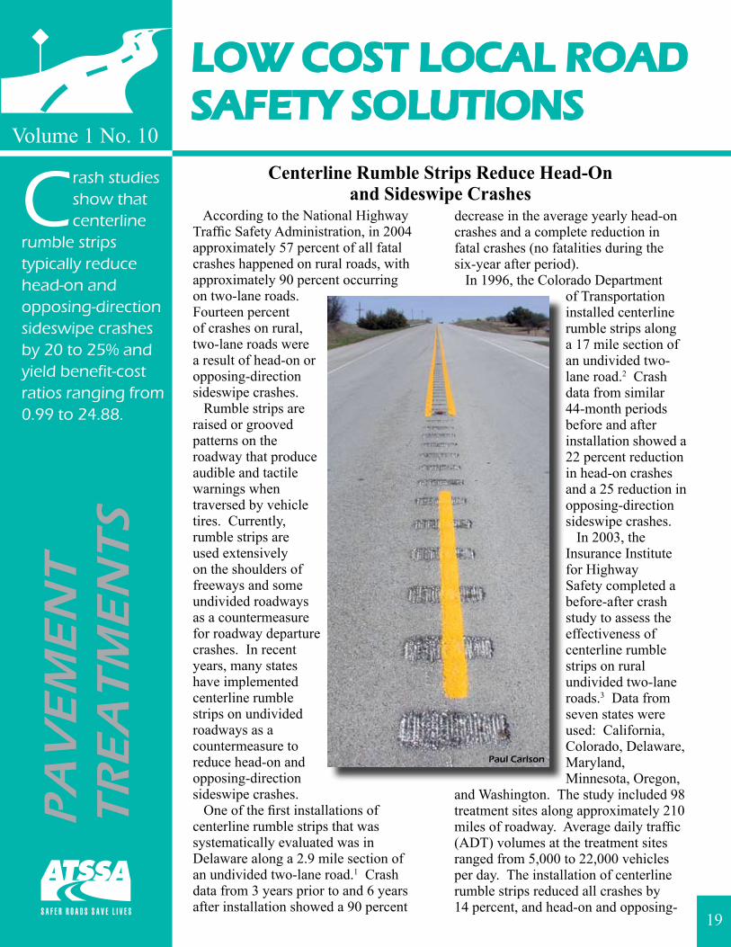
According to the National Highway Traffic Safety Administration, in 2004 approximately 57 percent of all fatal crashes happened on rural roads, with approximately 90 percent occurring on two-lane roads. Fourteen percent of crashes on rural, two-lane roads were a result of head-on or opposing-direction sideswipe crashes. Rumble strips are raised or grooved patterns on the roadway that produce audible and tactile warnings when traversed by vehicle tires. Currently, rumble strips are used extensively on the shoulders of freeways and some undivided roadways as a countermeasure for roadway departure crashes. In recent years, many states have implemented centerline rumble strips on undivided roadways as a countermeasure to reduce head-on and opposing-direction sideswipe crashes. One of the first installations of centerline rumble strips that was systematically evaluated was in Delaware along a 2.9 mile section of an undivided two-lane road.1 Crash data from 3 years prior to and 6 years after installation showed a 90 percent
decrease in the average yearly head-on crashes and a complete reduction in fatal crashes (no fatalities during the six-year after period). In 1996, the Colorado Department
of Transportation installed centerline rumble strips along a 17 mile section of an undivided two-lane road.2 Crash data from similar 44-month periods before and after installation showed a 22 percent reduction in head-on crashes and a 25 reduction in opposing-direction sideswipe crashes. In 2003, the Insurance Institute for Highway Safety completed a before-after crash study to assess the effectiveness of centerline rumble strips on rural undivided two-lane roads.3 Data from seven states were used: California, Colorado, Delaware, Maryland, Minnesota, Oregon,
and Washington. The study included 98 treatment sites along approximately 210 miles of roadway. Average daily traffic (ADT) volumes at the treatment sites ranged from 5,000 to 22,000 vehicles per day. The installation of centerline rumble strips reduced all crashes by 14 percent, and head-on and opposing-
PA
VE
ME
NT
TR
EA
TM
EN
TS
19
Paul Carlson
For more information on Low Cost Local Road Safety Solutions visit http://www.atssa.com.
1 Centerline Rumble Strips: The Delaware Experience. Delaware Department of Transportation.http://tcd.tamu.edu/documents/rumble/rumble1.htm.
2 Outcalt, W. Centerline Rumble Strips. Interim Report CDOT-DTD-R-2001-8. Colorado Department of Transportation, Denver, Colorado, August 2001. http://tcd.tamu.edu/documents/rumble/rumble1.htm.
3 Persaud, B.N., R.A. Retting, and C. Lyon. Crash Reduction Following Installation of Centerline Rumble Strips on Rural Two-Lane. Insurance Institute for Highway Safety, Arlington, Virginia, September 2003.http://tcd.tamu.edu/documents/rumble/rumble1.htm.
4 Carlson, P.J. and J.D. Miles. Effectiveness of Rumble Strips on Texas Highways: First Year Report. Report 0-4472-1. Texas Transportation Institute, College Station, Texas, September 2003. http://tti.tamu.edu/documents/0-4472-1.pdf.
5 Elongo, V.V., and D.A. Noyce. Safety Evaluation of Centerline Rumble Strips: Task 1-Centerline Rumble Strip Use Survey Results. Transportation Center University of Massachusetts-Amherst, Amherst, MA, September 2002. http://www.ecs.umass.edu/umtc/publicationsresearch.shtml.
6 Russell, E.R., and M.J. Rys. Centerline Rumble Strips. NCHRP Synthesis 339. Transportation Research Board, Washington, D.C., 2005.http://trb.org/publications/nchrp/nchrp_syn_339.pdf.
direction sideswipe crashes by 21 percent. In a recent study by the Texas Transportation Institute (TTI) researchers computed benefit-cost ratios for centerline rumble strips based on data from five states.4 Researchers assumed a 20 percent reduction in crashes as a result of centerline rumble strips and a cost of $1.50 per linear foot to install the centerline rumble strips, install pavement markings, and maintain traffic. The benefit-cost ratios computed varied from 0.99 to 24.88 depending upon the roadway volume. Another potential benefit of centerline rumble strips is their ability to enhance the visibility of centerline pavement markings in wet weather conditions. An on-going Texas Department of Transportation research project (0-5008) is currently evaluating the wet night visibility of
various types of pavement marking materials, including the application of pavement markings over rumble strips (referred to as rumble stripes). For more information on rumble stripes, please reference case study number eleven of this publication. Overall, evidence suggests that the installation of centerline rumble strips is a low cost safety improvement that reduces head-on and opposing-direction sideswipe crashes on undivided two-lane roadways. For more information on centerline rumble strips, please visit the Federal Highway Administration (FHWA) Highway Safety Program website at http://safety.fhwa.dot.gov/roadway_dept/rumble/center.htm or the TTI Traffic Control Devices website at http://tcd.tamu.edu/documents/rumble/rumble1.htm.
20
LOW COST LOCAL ROADSAFETY SOLUTIONS
Volume 1 No. 11
Studies show that edge line rumble
stripes can have retroreflectivity levels up to 20 times higher than an equivalent flat line in wet conditions after a year of service.
PA
VE
ME
NT
TR
EA
TM
EN
TS
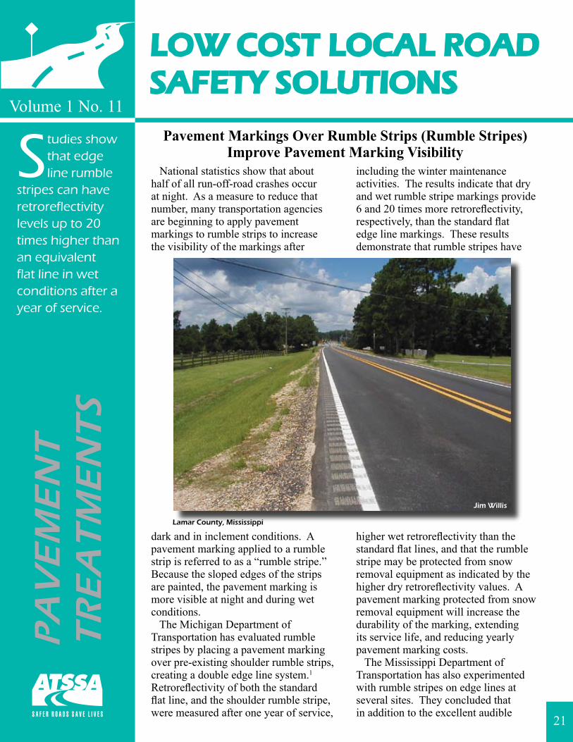
Pavement Markings Over Rumble Strips (Rumble Stripes)Improve Pavement Marking Visibility
National statistics show that about half of all run-off-road crashes occur at night. As a measure to reduce that number, many transportation agencies are beginning to apply pavement markings to rumble strips to increase the visibility of the markings after
dark and in inclement conditions. A pavement marking applied to a rumble strip is referred to as a “rumble stripe.” Because the sloped edges of the strips are painted, the pavement marking is more visible at night and during wet conditions. The Michigan Department of Transportation has evaluated rumble stripes by placing a pavement marking over pre-existing shoulder rumble strips, creating a double edge line system.1 Retroreflectivity of both the standard flat line, and the shoulder rumble stripe, were measured after one year of service,
including the winter maintenance activities. The results indicate that dry and wet rumble stripe markings provide 6 and 20 times more retroreflectivity, respectively, than the standard flat edge line markings. These results demonstrate that rumble stripes have
higher wet retroreflectivity than the standard flat lines, and that the rumble stripe may be protected from snow removal equipment as indicated by the higher dry retroreflectivity values. A pavement marking protected from snow removal equipment will increase the durability of the marking, extending its service life, and reducing yearly pavement marking costs. The Mississippi Department of Transportation has also experimented with rumble stripes on edge lines at several sites. They concluded that in addition to the excellent audible
21
Lamar County, Mississippi
Jim Willis
For more information on Low Cost Local Road Safety Solutions visit http://www.atssa.com.
1 Filcek, M.J., V. Oulevski, J.G. Morena, D.C. Long, and T.L. Maleck. Development of a Profiled Pavement Marking System: Investigation of the Dry/Wet-Night Retroreflectivity and Durability of Pavement Markings Placed in Milled Rumble Strips. Paper presented at the Transportation Research Board 83rd Annual Meeting, January 2004.
2 Willis, J. and W. Dean. Mississippi’s Rumble Stripe Experience. Presentation at the Transportation Research Board 83rd Annual Meeting, January 2004. http://tcd.tamu.edu/documents/rumble/rumble1.htm.
3 Carlson, P.J., J.D. Miles, M.P. Pratt, and A.M. Pike. Evaluation of Wet-Weather Pavement Markings: First Year Report. Report 0-5008-1. Texas Transportation Institute, College Station, Texas, 2005. http://tti.tamu.edu/documents/0-5008-1.pdf.
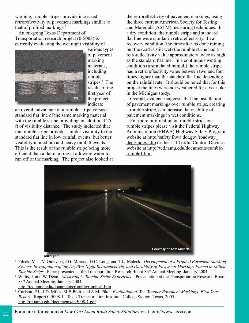
warning, rumble stripes provide increased retroreflectivity of pavement markings similar to that of profiled markings.2 An on-going Texas Department of Transportation research project (0-5008) is currently evaluating the wet night visibility of
various types of pavement marking materials, including rumble stripes.3 The results of the first year of the project indicate
an overall advantage of a rumble stripe versus a standard flat line of the same marking material with the rumble stripe providing an additional 25 ft of visibility distance. The study indicated that the rumble stripe provides similar visibility to the standard flat line in low rainfall events, but better visibility in medium and heavy rainfall events. This is the result of the rumble stripe being more efficient than a flat marking at allowing water to run off of the marking. The project also looked at
the retroreflectivity of pavement markings, using the three current American Society for Testing and Materials (ASTM) measuring techniques. In a dry condition, the rumble stripe and standard flat line were similar in retroreflectivity. In a recovery condition (the time after its done raining but the road is still wet) the rumble stripe had a retroreflectivity value approximately twice as high as the standard flat line. In a continuous wetting condition (a simulated rainfall) the rumble stripe had a retroreflectivity value between two and four times higher than the standard flat line depending on the rainfall rate. It should be noted that for this project the lines were not weathered for a year like in the Michigan study. Overall, evidence suggests that the installation of pavement markings over rumble strips, creating a rumble stripe, can increase the visibility of pavement markings in wet conditions. For more information on rumble strips or rumble stripes please visit the Federal Highway Administration (FHWA) Highway Safety Program website at http://safety.fhwa.dot.gov/roadway_dept/index.htm or the TTI Traffic Control Devices website at http://tcd.tamu.edu/documents/rumble/rumble1.htm.
22
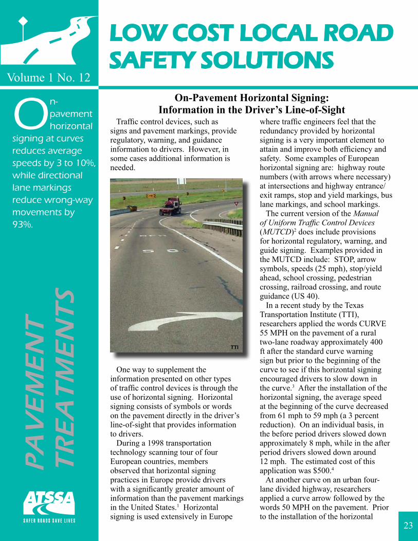
Michigan
TTI
Courtesy of Tom Maleck
LOW COST LOCAL ROADSAFETY SOLUTIONS
Volume 1 No. 12
On-pavement horizontal
signing at curves reduces average speeds by 3 to 10%, while directional lane markings reduce wrong-way movements by 93%.
On-Pavement Horizontal Signing:Information in the Driver’s Line-of-Sight
Traffic control devices, such as signs and pavement markings, provide regulatory, warning, and guidance information to drivers. However, in some cases additional information is needed.
One way to supplement the information presented on other types of traffic control devices is through the use of horizontal signing. Horizontal signing consists of symbols or words on the pavement directly in the driver’s line-of-sight that provides information to drivers. During a 1998 transportation technology scanning tour of four European countries, members observed that horizontal signing practices in Europe provide drivers with a significantly greater amount of information than the pavement markings in the United States.1 Horizontal signing is used extensively in Europe
where traffic engineers feel that the redundancy provided by horizontal signing is a very important element to attain and improve both efficiency and safety. Some examples of European horizontal signing are: highway route numbers (with arrows where necessary) at intersections and highway entrance/exit ramps, stop and yield markings, bus lane markings, and school markings. The current version of the Manual of Uniform Traffic Control Devices (MUTCD)2 does include provisions for horizontal regulatory, warning, and guide signing. Examples provided in the MUTCD include: STOP, arrow symbols, speeds (25 mph), stop/yield ahead, school crossing, pedestrian crossing, railroad crossing, and route guidance (US 40). In a recent study by the Texas Transportation Institute (TTI), researchers applied the words CURVE 55 MPH on the pavement of a rural two-lane roadway approximately 400 ft after the standard curve warning sign but prior to the beginning of the curve to see if this horizontal signing encouraged drivers to slow down in the curve.3 After the installation of the horizontal signing, the average speed at the beginning of the curve decreased from 61 mph to 59 mph (a 3 percent reduction). On an individual basis, in the before period drivers slowed down approximately 8 mph, while in the after period drivers slowed down around 12 mph. The estimated cost of this application was $500.4
At another curve on an urban four-lane divided highway, researchers applied a curve arrow followed by the words 50 MPH on the pavement. Prior to the installation of the horizontal
PA
VE
ME
NT
TR
EA
TM
EN
TS
23
TTI
For more information on Low Cost Local Road Safety Solutions visit http://www.atssa.com.
1 Tignor, S.C., L.L. Brown, J.L. Butner, R. Cunard, S.C. Davis, H.G. Hawkins, E.L. Fischer, M.R. Kehrli, P.F. Rusch, and W.S. Wainwright. Innovative Traffic Control Technology and Practices in Europe. Report FHWA-PL-99-021. Federal Highway Administration, Washington, D.C., August 1999.http://international.fhwa.dot.gov/Pdfs/Innovtce.pdf.
2 Manual on Uniform Traffic Control Devices for Streets and Highways. Federal Highway Administration, Washington, D.C., 2003 Edition with Revision No. 1 Incorporated, November 2004.http://mutcd.fhwa.dot.gov.
3 Chrysler, S.T. and S.D. Schrock. Field Evaluations and Driver Comprehension Studies of Horizontal Signing. Report 0-4471-2. Texas Transportation Institute, College Station, Texas, February 2005.http://tti.tamu.edu/documents/0-4471-2.pdf.
4 Cost varies per quantity.5 Retting, R.A., M.A. Greene, and J. Van Houten. Use of Pavement Markings To Reduce Rear-End Conflicts at
Commercial Driveway Locations. In Transportation Research Record 1605, Transportation Research Board, National Research Council, Washington, D.C., 1997, pp.106-110.
signing the average speed at the beginning of the horizontal curve was 66 mph, which was 11 mph over the posted speed limit of 55 mph. The posted speed limit violation rate at the beginning of the curve was 94 percent. After the installation of the horizontal signing, the average speed entering the curve decreased by 7 mph to 59 mph (a 10 percent reduction) and the posted speed limit violation rate was 78 percent (a 17 percent reduction). The estimated cost for this application was $400.4
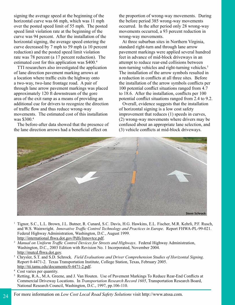
TTI researchers also investigated the application of lane direction pavement marking arrows at a location where traffic exits the highway onto a two-way, two-lane frontage road. A pair of through lane arrow pavement markings was placed approximately 120 ft downstream of the gore area of the exit ramp as a means of providing an additional cue for drivers to recognize the direction of traffic flow and thus reduce wrong-way movements. The estimated cost of this installation was $300.4
The before-after data showed that the presence of the lane direction arrows had a beneficial effect on
the proportion of wrong-way movements. During the before period 385 wrong-way movements occurred. In the after period only 28 wrong-way movements occurred, a 93 percent reduction in wrong-way movements. At three suburban sites in Northern Virginia, standard right-turn and through lane arrow pavement markings were applied several hundred feet in advance of mid-block driveways in an attempt to reduce rear-end collisions between non-turning vehicles and right-turning vehicles.5 The installation of the arrow symbols resulted in a reduction in conflicts at all three sites. Before the installation of the arrow symbols conflicts per 100 potential conflict situations ranged from 4.7 to 18.6. After the installation, conflicts per 100 potential conflict situations ranged from 2.4 to 9.2. Overall, evidence suggests that the installation of horizontal signing is a low cost safety improvement that reduces (1) speeds in curves, (2) wrong-way movements where drivers may be confused about an appropriate lane selection, and (3) vehicle conflicts at mid-block driveways.
24
Steve Schrock
LOW COST LOCAL ROADSAFETY SOLUTIONS
Volume 1 No. 13
Converging chevron pavement
marking patterns reduce 85th percentile speeds by 11 to 24% and result in a 43% reduction in crashes.
Converging Chevron Pavement Marking PatternSlows Down Traffic and Reduces Crashes
Speeding is one of the most prevalent factors contributing to traffic crashes. As drivers approach intersecting roadways, speeding extends the distance necessary to stop a vehicle so drivers have less time to react to vehicles entering the roadway. In addition, speeding reduces a driver’s ability to safely traverse curves. A converging chevron pavement marking pattern is one potential traffic control device that can be used to reduce speeds. The converging chevron pavement marking pattern consists of a series of white chevrons on the road surface with the spacing between chevrons decreasing as the driver travels over the pattern. This pattern creates the illusion that the vehicle is traveling faster than the vehicle’s actual speed and that the road is narrowing. In 1997, the City of Eagan, Minnesota applied a converging chevron pattern on a residential street (approximately 5,000 ADT) with a posted speed limit of 30 mph to reduce vehicle speeds.1 The cost to implement was less than $1,000. Before the application of the converging chevron pattern, the 85th percentile speed in the area was 41 mph
and the highest speed recorded was 58 mph. One week after the installation of the converging chevron pattern the 85th percentile speed was reduced to 35 mph (a 15 percent reduction)
and the highest speed recorded was 45 mph. Two years later the 85th percentile speed was still less than during the before period (39 mph which was a 5 percent reduction). In 2001, the city resurfaced the roadway and repainted the converging chevron pattern. Immediately after this, the 85th percentile speed was 35 mph and the highest speed recorded was 40 mph. Also in 1997, the City of Columbus, Ohio applied a converging chevron pattern on the approach to a double S-curve on a two-way, two-lane roadway.2 The
posted speed limit was 35 mph and the advisory speed was 15 mph. Prior to installation of the markings the 85th percentile speed at the curve was 37 mph. Approximately 15 months later, the 85th percentile speed was reduced to 33 mph (an 11 percent reduction). The City of Columbus is currently
PA
VE
ME
NT
TR
EA
TM
EN
TS
25
City of Eagan
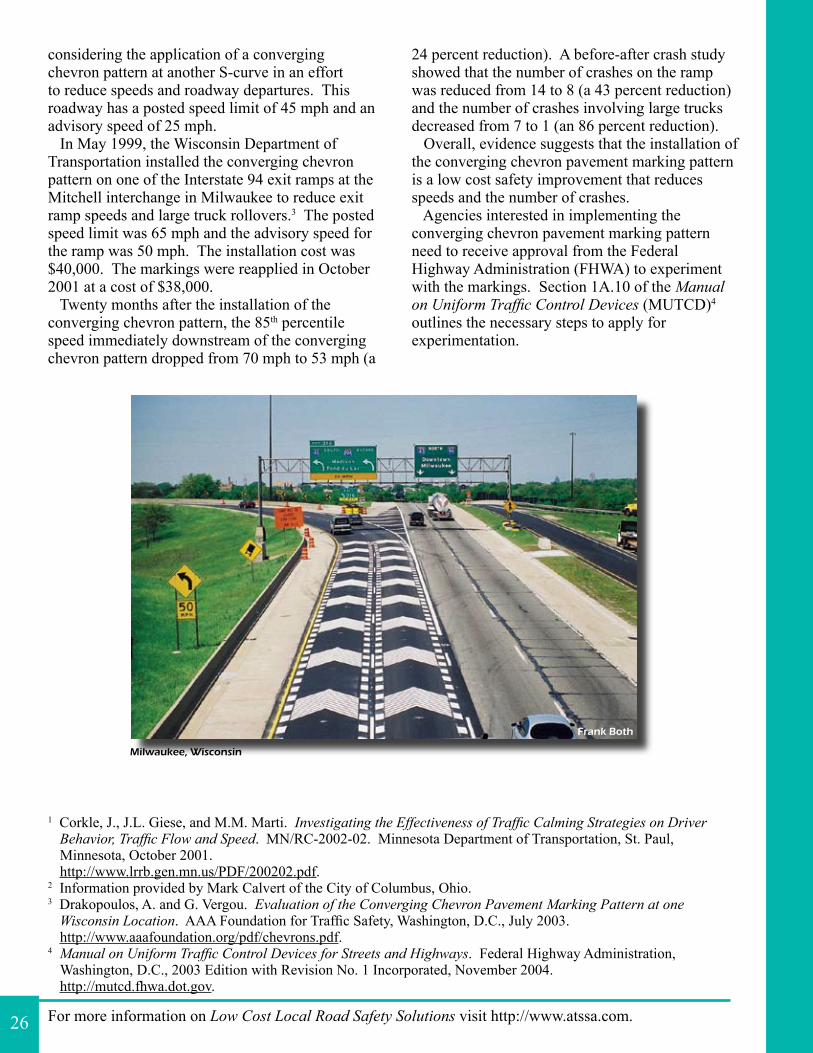
For more information on Low Cost Local Road Safety Solutions visit http://www.atssa.com.
1 Corkle, J., J.L. Giese, and M.M. Marti. Investigating the Effectiveness of Traffic Calming Strategies on Driver Behavior, Traffic Flow and Speed. MN/RC-2002-02. Minnesota Department of Transportation, St. Paul, Minnesota, October 2001. http://www.lrrb.gen.mn.us/PDF/200202.pdf.
2 Information provided by Mark Calvert of the City of Columbus, Ohio.3 Drakopoulos, A. and G. Vergou. Evaluation of the Converging Chevron Pavement Marking Pattern at one
Wisconsin Location. AAA Foundation for Traffic Safety, Washington, D.C., July 2003.http://www.aaafoundation.org/pdf/chevrons.pdf.
4 Manual on Uniform Traffic Control Devices for Streets and Highways. Federal Highway Administration, Washington, D.C., 2003 Edition with Revision No. 1 Incorporated, November 2004.http://mutcd.fhwa.dot.gov.
considering the application of a converging chevron pattern at another S-curve in an effort to reduce speeds and roadway departures. This roadway has a posted speed limit of 45 mph and an advisory speed of 25 mph. In May 1999, the Wisconsin Department of Transportation installed the converging chevron pattern on one of the Interstate 94 exit ramps at the Mitchell interchange in Milwaukee to reduce exit ramp speeds and large truck rollovers.3 The posted speed limit was 65 mph and the advisory speed for the ramp was 50 mph. The installation cost was $40,000. The markings were reapplied in October 2001 at a cost of $38,000. Twenty months after the installation of the converging chevron pattern, the 85th percentile speed immediately downstream of the converging chevron pattern dropped from 70 mph to 53 mph (a
24 percent reduction). A before-after crash study showed that the number of crashes on the ramp was reduced from 14 to 8 (a 43 percent reduction) and the number of crashes involving large trucks decreased from 7 to 1 (an 86 percent reduction). Overall, evidence suggests that the installation of the converging chevron pavement marking pattern is a low cost safety improvement that reduces speeds and the number of crashes. Agencies interested in implementing the converging chevron pavement marking pattern need to receive approval from the Federal Highway Administration (FHWA) to experiment with the markings. Section 1A.10 of the Manual on Uniform Traffic Control Devices (MUTCD)4 outlines the necessary steps to apply for experimentation.
26
Milwaukee, Wisconsin
Frank Both
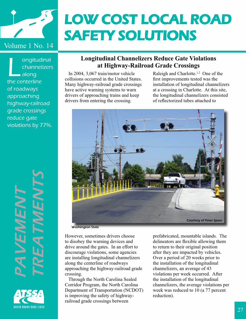
LOW COST LOCAL ROADSAFETY SOLUTIONS
Volume 1 No. 14
Longitudinal channelizers along
the centerline of roadways approaching highway-railroad grade crossings reduce gate violations by 77%.
PA
VE
ME
NT
TR
EA
TM
EN
TS
Longitudinal Channelizers Reduce Gate Violationsat Highway-Railroad Grade Crossings
In 2004, 3,067 train/motor vehicle collisions occurred in the United States. Many highway-railroad grade crossings have active warning systems to warn drivers of approaching trains and keep drivers from entering the crossing.
However, sometimes drivers choose to disobey the warning devices and drive around the gates. In an effort to discourage violations, some agencies are installing longitudinal channelizers along the centerline of roadways approaching the highway-railroad grade crossing. Through the North Carolina Sealed Corridor Program, the North Carolina Department of Transportation (NCDOT) is improving the safety of highway-railroad grade crossings between
Raleigh and Charlotte.1,2 One of the first improvements tested was the installation of longitudinal channelizers at a crossing in Charlotte. At this site, the longitudinal channelizers consisted of reflectorized tubes attached to
prefabricated, mountable islands. The delineators are flexible allowing them to return to their original position after they are impacted by vehicles. Over a period of 20 weeks prior to the installation of the longitudinal channelizers, an average of 43 violations per week occurred. After the installation of the longitudinal channelizers, the average violations per week was reduced to 10 (a 77 percent reduction).
27
Washington State
Courtesy of Peter Speer
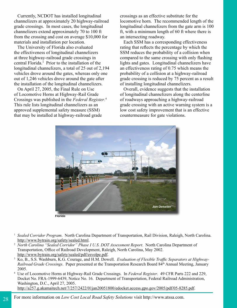
For more information on Low Cost Local Road Safety Solutions visit http://www.atssa.com.
1 Sealed Corridor Program. North Carolina Department of Transportation, Rail Division, Raleigh, North Carolina. http://www.bytrain.org/safety/sealed.html.
2 North Carolina “Sealed Corridor” Phase I U.S. DOT Assessment Report. North Carolina Department of Transportation, Office of Railroad Development, Raleigh, North Carolina, May 2002.http://www.bytrain.org/safety/sealed/pdf/esvolpe.pdf.
3 Ko, B., S.S. Washburn, K.G. Courage, and H.M. Dowell. Evaluation of Flexible Traffic Separators at Highway-Railroad Grade Crossings. Paper presented at the Transportation Research Board 84th Annual Meeting, January 2005.
4 Use of Locomotive Horns at Highway-Rail Grade Crossings. In Federal Register. 49 CFR Parts 222 and 229, Docket No. FRA-1999-6439, Notice No. 16. Department of Transportation, Federal Railroad Administration, Washington, D.C., April 27, 2005.http://a257.g.akamaitech.net/7/257/2422/01jan20051800/edocket.access.gpo.gov/2005/pdf/05-8285.pdf.
Currently, NCDOT has installed longitudinal channelizers at approximately 20 highway-railroad grade crossings. In most cases, the longitudinal channelizers extend approximately 70 to 100 ft from the crossing and cost on average $10,000 for materials and installation per location. The University of Florida also evaluated the effectiveness of longitudinal channelizers at three highway-railroad grade crossings in central Florida.3 Prior to the installation of the longitudinal channelizers, a total of 25 out of 2,194 vehicles drove around the gates, whereas only one out of 1,246 vehicles drove around the gate after the installation of the longitudinal channelizers. On April 27, 2005, the Final Rule on Use of Locomotive Horns at Highway-Rail Grade Crossings was published in the Federal Register.4 This rule lists longitudinal channelizers as an approved supplemental safety measure (SSM) that may be installed at highway-railroad grade
crossings as an effective substitute for the locomotive horn. The recommended length of the longitudinal channelizers from the gate arm is 100 ft, with a minimum length of 60 ft where there is an intersecting roadway. Each SSM has a corresponding effectiveness rating that reflects the percentage by which the SSM reduces the probability of a collision when compared to the same crossing with only flashing lights and gates. Longitudinal channelizers have an effectiveness rating of 0.75 which means the probability of a collision at a highway-railroad grade crossing is reduced by 75 percent as a result of installing longitudinal channelizers. Overall, evidence suggests that the installation of longitudinal channelizers along the centerline of roadways approaching a highway-railroad grade crossing with an active warning system is a low cost safety improvement that is an effective countermeasure for gate violations.
28
Florida
Jon Detwiler
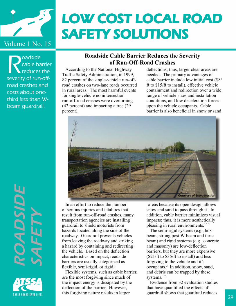
LOW COST LOCAL ROADSAFETY SOLUTIONS
Volume 1 No. 15
RO
AD
SID
ESA
FET
Y
Roadside cable barrier reduces the
severity of run-off-road crashes and costs about one-third less than W-beam guardrail.
Roadside Cable Barrier Reduces the Severityof Run-Off-Road Crashes
According to the National Highway Traffic Safety Administration, in 1999, 82 percent of the single-vehicle run-off-road crashes on two-lane roads occurred in rural areas. The most harmful events for single-vehicle nonintersection run-off-road crashes were overturning (42 percent) and impacting a tree (29 percent).
In an effort to reduce the number of serious injuries and fatalities that result from run-off-road crashes, many transportation agencies are installing guardrail to shield motorists from hazards located along the side of the roadway. Guardrail prevents vehicles from leaving the roadway and striking a hazard by containing and redirecting the vehicle. Based on the deflection characteristics on impact, roadside barriers are usually categorized as flexible, semi-rigid, or rigid.1 Flexible systems, such as cable barrier, are the most forgiving since much of the impact energy is dissipated by the deflection of the barrier. However, this forgiving nature results in larger
deflections; thus, larger clear areas are needed. The primary advantages of cable barrier include low initial cost ($8/ft to $15/ft to install), effective vehicle containment and redirection over a wide range of vehicle sizes and installation conditions, and low deceleration forces upon the vehicle occupants. Cable barrier is also beneficial in snow or sand
areas because its open design allows snow and sand to pass through it. In addition, cable barrier minimizes visual impacts; thus, it is more aesthetically pleasing in rural environments.1,2,3 The semi-rigid systems (e.g., box beam, strong post W-beam and thrie beam) and rigid systems (e.g., concrete and masonry) are low-deflection barriers, but they are more expensive ($21/ft to $35/ft to install) and less forgiving to the vehicle and it’s occupants.2 In addition, snow, sand, and debris can be trapped by these systems.1,2
Evidence from 32 evaluation studies that have quantified the effects of guardrail shows that guardrail reduces
29
Courtesy of Steve Kessler
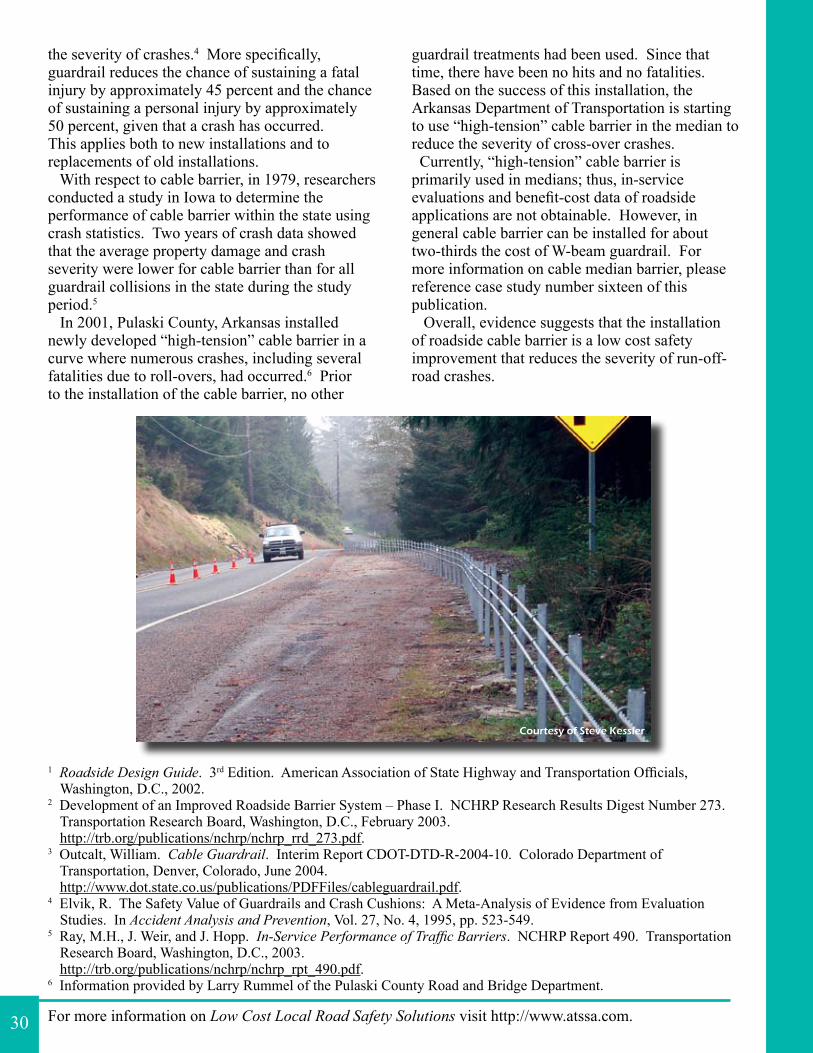
For more information on Low Cost Local Road Safety Solutions visit http://www.atssa.com.
1 Roadside Design Guide. 3rd Edition. American Association of State Highway and Transportation Officials, Washington, D.C., 2002.
2 Development of an Improved Roadside Barrier System – Phase I. NCHRP Research Results Digest Number 273. Transportation Research Board, Washington, D.C., February 2003.http://trb.org/publications/nchrp/nchrp_rrd_273.pdf.
3 Outcalt, William. Cable Guardrail. Interim Report CDOT-DTD-R-2004-10. Colorado Department of Transportation, Denver, Colorado, June 2004.http://www.dot.state.co.us/publications/PDFFiles/cableguardrail.pdf.
4 Elvik, R. The Safety Value of Guardrails and Crash Cushions: A Meta-Analysis of Evidence from Evaluation Studies. In Accident Analysis and Prevention, Vol. 27, No. 4, 1995, pp. 523-549.
5 Ray, M.H., J. Weir, and J. Hopp. In-Service Performance of Traffic Barriers. NCHRP Report 490. Transportation Research Board, Washington, D.C., 2003.http://trb.org/publications/nchrp/nchrp_rpt_490.pdf.
6 Information provided by Larry Rummel of the Pulaski County Road and Bridge Department.
the severity of crashes.4 More specifically, guardrail reduces the chance of sustaining a fatal injury by approximately 45 percent and the chance of sustaining a personal injury by approximately 50 percent, given that a crash has occurred. This applies both to new installations and to replacements of old installations. With respect to cable barrier, in 1979, researchers conducted a study in Iowa to determine the performance of cable barrier within the state using crash statistics. Two years of crash data showed that the average property damage and crash severity were lower for cable barrier than for all guardrail collisions in the state during the study period.5 In 2001, Pulaski County, Arkansas installed newly developed “high-tension” cable barrier in a curve where numerous crashes, including several fatalities due to roll-overs, had occurred.6 Prior to the installation of the cable barrier, no other
guardrail treatments had been used. Since that time, there have been no hits and no fatalities. Based on the success of this installation, the Arkansas Department of Transportation is starting to use “high-tension” cable barrier in the median to reduce the severity of cross-over crashes. Currently, “high-tension” cable barrier is primarily used in medians; thus, in-service evaluations and benefit-cost data of roadside applications are not obtainable. However, in general cable barrier can be installed for about two-thirds the cost of W-beam guardrail. For more information on cable median barrier, please reference case study number sixteen of this publication. Overall, evidence suggests that the installation of roadside cable barrier is a low cost safety improvement that reduces the severity of run-off-road crashes.
30
Courtesy of Steve Kessler
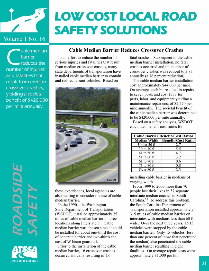
LOW COST LOCAL ROADSAFETY SOLUTIONS
Volume 1 No. 16
Cable median barrier reduces the
number of injuries and fatalities that result from median crossover crashes, yielding a societal benefit of $420,000 per mile annually.
Cable Median Barrier Reduces Crossover Crashes In an effort to reduce the number of serious injuries and fatalities that result from median crossover crashes, many state departments of transportation have installed cable median barrier to contain and redirect errant vehicles. Based on
these experiences, local agencies are also starting to consider the use of cable median barrier. In the 1990s, the Washington State Department of Transportation (WSDOT) installed approximately 25 miles of cable median barrier in three locations along Interstate 5.1 Cable median barrier was chosen since it could be installed for about one-third the cost of concrete barrier and two-thirds the cost of W-beam guardrail. Prior to the installation of the cable median barrier, 16 crossover crashes occurred annually resulting in 1.6
fatal crashes. Subsequent to the cable median barrier installation, no fatal crashes occurred and the number of crossover crashes was reduced to 3.83 annually (a 76 percent reduction). The cable median barrier installation cost approximately $44,000 per mile. On average, each hit resulted in repairs to seven posts and cost $733 for parts, labor, and equipment yielding a maintenance repair cost of $2,570 per mile annually. The societal benefit of the cable median barrier was determined to be $420,000 per mile annually. Based on a safety analysis, WSDOT calculated benefit-cost ratios for
installing cable barrier in medians of varying width. From 1999 to 2000 more than 70 people lost their lives in 57 separate interstate median crashes in South Carolina.2,3 To address this problem, the South Carolina Department of Transportation installed approximately 315 miles of cable median barrier on interstates with medians less than 60 ft wide. Over the next three years, 1,913 vehicles were stopped by the cable median barrier. Only 15 vehicles (less than one percent of those that penetrated the median) also penetrated the cable median barrier resulting in eight fatalities. On average repair costs were approximately $1,000 per hit.
RO
AD
SID
ESA
FET
Y
31
SCDOT
For more information on Low Cost Local Road Safety Solutions visit http://www.atssa.com.
1 McClanahan, D., R.B. Albin, and J.C. Milton. Washington State Cable Median Barrier In-Service Study. Paper presented at the Transportation Research Board 83rd Annual Meeting, January 2004.
2 Median Barriers. Federal Highway Administration website. Accessed December 2005.http://safety.fhwa.dot.gov/tools/median_barrier.htm.
3 Zeitz, R. Low-Cost Solutions Yield Big Savings. In Public Roads, Vol. 67, No. 3., November/December 2003.http://www.tfhrc.gov/pubrds/03nov/11.htm.
4 UDOT Using Innovative Cable Barrier. In FastLane Newsletter, Utah Department of Transportation, Spring 2004. http://www.udot.utah.gov/index.php/m=c/tid=792/item=5304/d=full.
5 Lee, R.B. Oklahoma DOT Experience with Brifen Wire Rope Safety Fence on Lake Hefner Parkway in Oklahoma City. Oklahoma Department of Transportation Internal Memorandum, June 24, 2004.
6 Scanning Tour for High Tension Cable Median Barrier. Draft report. Federal Highway Administration, Washington, D.C., December 2005.
7 Braceras, C. Utah Demonstrates That Cable Barriers Virtually Eliminate Cross-Over Crashes. In Lifelines, AASHTO-NCHRP Project 17-18, Vol. 2, No. 2, August 2005.http://safety.transportation.org/doc/lifelines-5.pdf.
8 Neuman, T.R., R. Pfefer, K.L. Slack, H. McGee, L. Prothe, K. Eccles, and F. Council. Guidance for Implementation of the AASHTO Strategic Highway Safety Plan Volume 4: A Guide for Addressing Head-On Collisions. NCHRP Report 500. Transportation Research Board, Washington, D.C., 2003.http://gulliver.trb.org/publications/nchrp/nchrp_rpt_500v4.pdf.
9 Ross, H.E., Jr., D.L. Sicking, R.A. Zimmer, and J.D. Michie. Recommended Procedures for the Safety Performance Evaluation of Highway Features. NCHRP Report 350. Transportation Research Board, Washington, D.C., 1993.
In September 2001, the Oklahoma Department of Transportation installed cable median barrier on a 7-mile section of freeway which experienced 22 crossover crashes involving 10 fatalities from 1996 to 2001.4,5,6 As of May 2004, the cable median barrier had been hit 238 times resulting in only three injuries and no fatalities. On average, repairs consisted of replacing five posts and cost $270 for parts, labor, and traffic control. A second installation of cable median barrier along approximately 6 miles of another freeway was completed in September 2004.6 During the five years prior to the installation of the cable median barrier, six fatalities, 16 injuries, and nine property damage only crashes occurred. As of September 2005 the cable median barrier had been hit 21 times resulting in only one property damage only crash (i.e., no injuries or fatalities). Recently, the Utah Department of Transportation (UDOT) also chose to use cable barrier instead of concrete barrier in medians since cable barrier could be installed for about one-third the cost of concrete barrier.7 By late 2003, UDOT had installed cable median barrier at six locations on two interstates. Prior to the installation of the cable median barrier, an average of five fatalities and 22 serious injuries occurred. Since the installation of the cable median barrier there have been no fatalities and only one serious injury has been reported. Out of the more than 120 vehicle
hits, only two vehicles crossed into on-coming traffic. The Federal Highway Administration (FHWA) recommends the use of median barriers as a safety technology that prevents median crossover head-on crashes.2,8 The FHWA requires that all median barriers used on the National Highway System meet federal standards contained in the National Cooperative Highway Research Program (NCHRP) Report 350.9
Overall, evidence suggests that the installation of cable median barrier is a low cost safety improvement that reduces the number of injuries and fatalities that result from median crossover crashes.
32
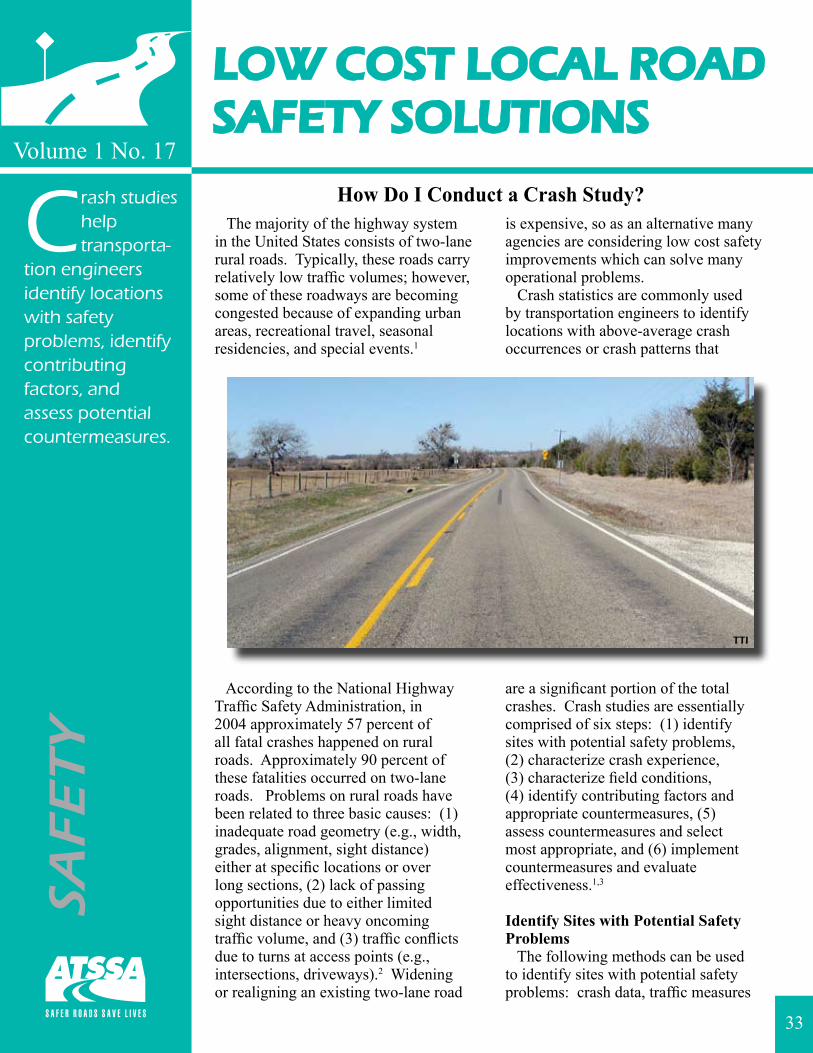
LOW COST LOCAL ROADSAFETY SOLUTIONS
Volume 1 No. 17
How Do I Conduct a Crash Study? The majority of the highway system in the United States consists of two-lane rural roads. Typically, these roads carry relatively low traffic volumes; however, some of these roadways are becoming congested because of expanding urban areas, recreational travel, seasonal residencies, and special events.1
According to the National Highway Traffic Safety Administration, in 2004 approximately 57 percent of all fatal crashes happened on rural roads. Approximately 90 percent of these fatalities occurred on two-lane roads. Problems on rural roads have been related to three basic causes: (1) inadequate road geometry (e.g., width, grades, alignment, sight distance) either at specific locations or over long sections, (2) lack of passing opportunities due to either limited sight distance or heavy oncoming traffic volume, and (3) traffic conflicts due to turns at access points (e.g., intersections, driveways).2 Widening or realigning an existing two-lane road
is expensive, so as an alternative many agencies are considering low cost safety improvements which can solve many operational problems. Crash statistics are commonly used by transportation engineers to identify locations with above-average crash occurrences or crash patterns that
are a significant portion of the total crashes. Crash studies are essentially comprised of six steps: (1) identify sites with potential safety problems, (2) characterize crash experience, (3) characterize field conditions, (4) identify contributing factors and appropriate countermeasures, (5) assess countermeasures and select most appropriate, and (6) implement countermeasures and evaluate effectiveness.1,3
Identify Sites with Potential Safety Problems The following methods can be used to identify sites with potential safety problems: crash data, traffic measures
SAFE
TY
Crash studies help transporta-
tion engineers identify locations with safety problems, identify contributing factors, and assess potential countermeasures.
33
TTI
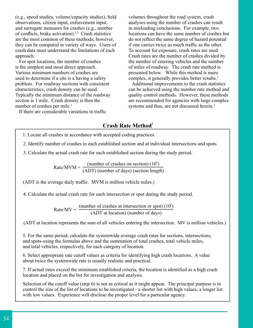
(e.g., speed studies, volume/capacity studies), field observations, citizen input, enforcement input, and surrogate measures for crashes (e.g., number of conflicts, brake activation).1,3 Crash statistics are the most common of these methods; however, they can be computed in variety of ways. Users of crash data must understand the limitations of each approach. For spot locations, the number of crashes is the simplest and most direct approach. Various minimum numbers of crashes are used to determine if a site is a having a safety problem. For roadway sections with consistent characteristics, crash density can be used. Typically the minimum distance of the roadway section is 1 mile. Crash density is then the number of crashes per mile.1
If there are considerable variations in traffic
volumes throughout the road system, crash analyses using the number of crashes can result in misleading conclusions. For example, two locations can have the same number of crashes but do not reflect the same degree of hazard potential if one carries twice as much traffic as the other. To account for exposure, crash rates are used. Crash rates are the number of crashes divided by the number of entering vehicles and the number of miles of roadway. The crash rate method is presented below. While this method is more complex, it generally provides better results.1 Additional improvements to the crash statistics can be achieved using the number rate method and quality control methods. However, these methods are recommended for agencies with large complex systems and thus, are not discussed herein.1
34
Two additional crash evaluation methods that can be used are crash severity measures and crash indexes. Crash severity measures allow for more severe crashes (e.g., fatal and injury crashes) to be given more importance than less severe crashes (e.g., property-damage-only crashes). An overall crash index can be used to combine different methods into a single measure. Each measure can be weighted the same or differently. The combination minimizes the weaknesses of the individual measures.1
Characterize Crash Experience Once the sites with potential safety problems have been identified, the crash experience needs to be characterized. Activities that help to characterize the crash experience include: a list of the types of crashes, a review of crash report forms, preparation of collision diagrams, and field visits. The information gathered in this step helps identify contributing factors which can be used to identify appropriate countermeasures.1
Characterize Field Conditions Next, the physical condition of the site must be investigated. The geometries of the roadway are needed as a basis for all data collected about the roadway. On-site observation by an engineer is recommended. The timing of the visit should correspond to the safety problem; thus, the visit may need to take place during off-peak periods or at night. Photographs are a good tool for documenting geometric or operational problems for later review. Condition diagrams may also be developed. Condition diagrams are scale drawings of the location of interest that show geometric and traffic control details. Traffic volume counts and vehicle classification counts are also needed. In addition, supplementary traffic studies can be employed to further define the safety problem and help identify appropriate countermeasures.1
Identify Contributing Factors and Appropriate Countermeasures The next step is to determine potential countermeasures that could effectively correct or improve the situation. Countermeasures can be identified using the following sources:
detailed investigations of crashes, review of site plans, site visits, other transportation engineering studies, practices and previous experiences, and technical literature.1 Many references are available that suggest countermeasures for certain situations including: the Institute of Transportation Engineers (ITE) Traffic Engineering Handbook;3 National Cooperative Highway Research Program (NCHRP) Report 440-Accident Mitigation Guide for Congested Rural Two-Lane Highways;1 and the NCHRP 500 report series.4
Assess Countermeasures and Select Most Appropriate When selecting the most appropriate countermeasure the following should be considered: (1) identify all practical countermeasures including doing nothing, (2) identify all practical combinations of countermeasures, (3) identify practical limitations and constraints, and (4) for each alternative identify the potential effect. Documentation of the data and process is needed.1 The proposed countermeasures should be evaluated to determine which will provide the greatest return. Evaluations may be as simple as listing the advantages and disadvantages of each alternative. In contrast, a complete economic analysis using benefit-cost or cost effectiveness could be completed. Typically, evaluations involve the following six steps: (1) estimate net crash reduction, (2) assign values to crash reduction, (3) estimate secondary benefits, (4) estimate improvements costs, (5) analyze effectiveness at each location, and (6) assign program priorities. The final part of this step is to narrow down the range of possibilities to one or more measures.1
Implement Countermeasures and Evaluate Effectiveness The final step in the process is to implement the selected improvements and evaluate their effectiveness. The Federal Highway Administration (FHWA) developed a detailed procedure consisting of the following six tasks: (1) develop evaluation plan, (2) collect and reduce data, (3) compare measures of effectiveness, (4) perform statistical tests, (5) perform economic analysis, and (6) prepare
35
1 Fitzpatrick, K., K. Balke, D.W. Harwood, and I.B. Anderson. Accident Mitigation Guide for Congested Rural Two-Lane Highways. NCHRP Report 440. Transportation Research Board, National Research Council, Washington, D.C., 2000.
2 Harwood, D.W. and C.J. Hoban. Low-Cost Methods for Improving Traffic Operations on Two-Lane Roads: Informational Guide. FHWA-IP-87-2. Federal Highway Administration, Washington, D.C., January 1987.
3 Pline, J. Traffic Engineering Handbook. 5th Edition. Institute of Transportation Engineers, Washington, D.C., 1999.
4 NCHRP Report 500 Series, Volumes 1-16 (more forthcoming). Transportation Research Board, Washington, D.C., 2003-2005. http://www4.trb.org/trb/crp.nsf/All+Projects/NCHRP+17-18(3) orhttp://safety.transportation.org/guides.aspx.
5 Highway Safety Evaluation – Procedural Guide. FHWA-TS-81-219. Federal Highway Administration, Washington, D.C., November 1981.
6 Robertson, H.D., J.E. Hummer, and D.C. Nelson. Manual of Transportation Engineering Studies. Institute of Transportation Engineers, Washington, D.C., 1994.
7 Council, F.M., et al. Accident Research Manual. FHWA/RD-80/016. Federal Highway Administration, Washington, D.C., February 1980.
8 Hauer. E. Observational Before-After Studies in Road Safety. Pergamon/Elsevier Science, Inc., Tanytown, New York, 1997.
9 Latham, F.E. and J.W. Trombly. Low Cost Traffic Engineering Improvements: A Primer. FHWA-OP-03-078. Federal Highway Administration, Washington, D.C., April 2003.http://ops.fhwa.dot.gov/publications/low_cost_traf/low_cost_traf.pdf.
evaluation documentation.5 Several sources provide additional information on conducting evaluation studies.5,6,7,8,9 The following four evaluation approaches are also recommended by the FHWA: before-and-after study with control sites, before-and-after study, comparative parallel study, and before, during, and after study. Of these techniques, the before-and-after study with control sites is considered to be the most desirable. This technique involves matching the improved sites with similar comparison sites that are not improved. By using a comparison site, the crash experience that would have been observed at the improved sites had the improvement not been made can be estimated.1
The phenomenon known as regression to the mean affects the validity of a before-and-after study of a crash countermeasure. If a safety improvement is implemented at a site based on a high short-term crash experience, it is likely that even if no improvement was made the crash experience would decrease (regress to the mean). Thus, regression to the mean effects can be mistaken for the effects of crash countermeasures.1 Newer Empirical Bayes techniques account for the effect of regression to the mean, but are more complicated.8
In conclusion, the majority of the highway system in the United States consists of two-lane rural roads. According to the National Highway Traffic Safety Administration, in 2004 approximately 90 percent of the fatalities that happened on rural roads occurred on two-lane roads. Crash studies can be used by transportation engineers to identify locations with safety problems, identify contributing factors, and assess potential countermeasures.
36
Federal Highway Administration Office of Safety website. http://safety.fhwa.dot.gov/.
Guidance on Traffic Control Devices at Highway-Rail Grade Crossings. Highway-Rail Grade Crossing Technical Working Group, Federal Highway Administration, November 2002.http://safety.fhwa.dot.gov/media/twgreport.htm.
Let’s Work Together to Save Lives – Life-Saving Strategies for America’s Highways. FHWA-SA-04-001. Federal Highway Administration, Washington, D.C.http://safety.fhwa.dot.gov/media/pdf/sa04001.pdf.
Low Cost Safety Improvements Workshop. Federal Highway Administration. Contact Fred Ranck of the FHWA Resource Center in Olympia Fields, Illinois at 708-283-3545 or [email protected].
Low Cost Traffic Engineering Improvements: A Primer. Latham, F.E. and J.W. Trombly. FHWA-OP-03-078. Federal Highway Administration, Washington, D.C., April 2003. http://ops.fhwa.dot.gov/publications/low_cost_traf/low_cost_traf.pdf.
Maintenance of Signs and Sign Supports for Local Roads and Streets – A Guide for Street and Highway Maintenance Personnel. Federal Highway Administration, Washington, D.C.http://safety.fhwa.dot.gov/media/pdf/sign_support.pdf.
Manual on Uniform Traffic Control Devices for Streets and Highways. 2003 Edition with Revision No. 1 Incorporated. Federal Highway Administration, Washington, D.C., November 2004.http://www.atssa.com (Click on the Online Store)
NCHRP Report 350 Recommended Procedures for the Safety Performance Evaluation of Highway Features. Ross, H.E., Jr., D.L. Sicking, R.A. Zimmer, and J.D. Michie. Transportation Research Board, Washington, D.C., 1993.http://safety.fhwa.dot.gov/roadway_dept/road_hardware/nchrp_350.htm.
NCHRP Report 440 Accident Mitigation Guide for Congested Rural Two-Lane Highways. Fitzpatrick, K., K. Balke, D.W. Harwood, and I.B. Anderson. Transportation Research Board, Washington, D.C., 2000.
NCHRP Report 492 Roadside Safety Analysis Program (RSAP) – Engineer’s Manual. Mak, K.K. and D.L. Sicking. Transportation Research Board, Washington, D.C., 2003.http://gulliver.trb.org/publications/nchrp/nchrp_rpt_492.pdf.
ADDITIONAL RESOURCES
37
NCHRP Report 500 Guidance for Implementation of the AASHTO Strategic Highway Safety Plan, Volumes 1-17 (more forthcoming). Transportation Research Board, Washington, D.C., 2003-2005.http://www.atssa.com (Click on the SAFETEA-LU Vault)
• Volume 1: A Guide for Addressing Aggressive-Driving Collisions• Volume 2: A Guide for Addressing Collisions Involving Unlicensed Drives and Drivers
with Suspended or Revoked Licenses• Volume 3: A Guide for Addressing Collisions with Trees in Hazardous Locations• Volume 4: A Guide for Addressing Head-On Collisions.• Volume 5: A Guide for Addressing Unsignalized Intersection Collisions• Volume 6: A Guide for Addressing Run-Off-Road Collisions• Volume 7: A Guide for Reducing Collisions on Horizontal Curves• Volume 8: A Guide for Reducing Collisions Involving Utility Poles• Volume 9: A Guide for Reducing Collisions Involving Older Drivers• Volume 10: A Guide for Reducing Collision Involving Pedestrians• Volume 11: A Guide for Increasing Seat Belt Use• Volume 12: A Guide for Reducing Collisions at Signalized Intersections• Volume 13: A Guide for Reducing Collisions Involving Heavy Trucks• Volume 14: A Guide for Reducing Crashed Involving Drowsy and Distracted Drivers• Volume 15: A Guide for Enhancing Rural Emergency Medical Services• Volume 16: A Guide for Reducing Alcohol-Related Collisions• Volume 17: A Guide for Reducing Work Zone Collisions
NCHRP Research Results Digest 299 Crash Reduction Factors for Traffic Engineering and Intelligent Transportation System (ITS) Improvements: State-of-Knowledge Report. Transportation Research Board, Washington, D.C., November 2005.http://trb.org/publications/nchrp/nchrp_rrd_299.pdf.
NCHRP Synthesis 306 Long-Term Pavement Marking Practices – A Synthesis of Highway Practice. Migletz, J. and J. Graham. Transportation Research Board, Washington, D.C., 2002.http://gulliver.trb.org/publications/nchrp/nchrp_syn_306_1-14.pdf.http://gulliver.trb.org/publications/nchrp/nchrp_syn_306_15-21.pdf.http://gulliver.trb.org/publications/nchrp/nchrp_syn_306_22-37.pdf.http://gulliver.trb.org/publications/nchrp/nchrp_syn_306_38-61.pdf.http://gulliver.trb.org/publications/nchrp/nchrp_syn_306_62-97.pdf.http://gulliver.trb.org/publications/nchrp/nchrp_syn_306_98-104.pdf.http://gulliver.trb.org/publications/nchrp/nchrp_syn_306_105-123.pdf.http://gulliver.trb.org/publications/nchrp/nchrp_syn_306_124-142.pdf.http://gulliver.trb.org/publications/nchrp/nchrp_syn_306_143-165.pdf.
38
Roadside Design Guide. 3rd Edition. American Association of State Highway and Transportation Officials, Washington, D.C., 2002.
Roadway Delineation Practices Handbook. Migletz. J., J.K. Fish, and J.L. Graham. FHWA-SA-93-001. Federal Highway Administration, Washington, D.C., August 1994.http://www.fhwa.dot.gov/tfhrc/safety/pubs/93001/93001.pdf.
Roadway Safety Guide. Roadway Safety Foundation. http://www.roadwaysafety.org/guide.PDF.
Safety Conscious Planning Brochure. Federal Highway Administration, Washington, D.C.http://safety.fhwa.dot.gov/media/brochures.htm.
Standard Highway Signs. 2004 Edition. Federal Highway Administration, Washington, D.C., 2004.
http://www.atssa.com. (Click on the Online Store)The Safety Edge – Pavement Edge Treatment. Federal Highway Administration, Washington, D.C.http://safety.fhwa.dot.gov/media/pdf/safetyedge.pdf.
Traffic Engineering Handbook. 5th Edition. Pline, J. Institute of Transportation Engineers, Washington, D.C., 1999.
39

For additional copies visit the Online Store of ATSSA.com, call the Products Department at (877) 642-4637 or write to: ATSSA15 Riverside Parkway, Suite 100Fredericksburg, VA 22406
To order additional copies of Low Cost Local Road Safety Solutions at $19.95 each, e-mail [email protected], or call (877) 642-4637, ext. 135. A .pdf version of this book is available in the “Members Only” section of ATSSA.com.
Copies are free to ATSSA and NACE members.


American Traffic Safety Services Association15 Riverside Parkway, Suite 100Fredericksburg, Virginia 22406
Visit our website at ATSSA.com