Embed Size (px)
Citation preview
Bruce A. Banks, Kim K. de Groh, and Sharon K. MillerGlenn Research Center, Cleveland, Ohio
Low Earth Orbital Atomic Oxygen InteractionsWith Spacecraft Materials
NASA/TM—2004-213400
November 2004
https://ntrs.nasa.gov/search.jsp?R=20040191331 2018-06-22T20:37:29+00:00Z

The NASA STI Program Office . . . in Profile
Since its founding, NASA has been dedicated tothe advancement of aeronautics and spacescience. The NASA Scientific and TechnicalInformation (STI) Program Office plays a key partin helping NASA maintain this important role.
The NASA STI Program Office is operated byLangley Research Center, the Lead Center forNASA’s scientific and technical information. TheNASA STI Program Office provides access to theNASA STI Database, the largest collection ofaeronautical and space science STI in the world.The Program Office is also NASA’s institutionalmechanism for disseminating the results of itsresearch and development activities. These resultsare published by NASA in the NASA STI ReportSeries, which includes the following report types:
• TECHNICAL PUBLICATION. Reports ofcompleted research or a major significantphase of research that present the results ofNASA programs and include extensive dataor theoretical analysis. Includes compilationsof significant scientific and technical data andinformation deemed to be of continuingreference value. NASA’s counterpart of peer-reviewed formal professional papers buthas less stringent limitations on manuscriptlength and extent of graphic presentations.
• TECHNICAL MEMORANDUM. Scientificand technical findings that are preliminary orof specialized interest, e.g., quick releasereports, working papers, and bibliographiesthat contain minimal annotation. Does notcontain extensive analysis.
• CONTRACTOR REPORT. Scientific andtechnical findings by NASA-sponsoredcontractors and grantees.
• CONFERENCE PUBLICATION. Collectedpapers from scientific and technicalconferences, symposia, seminars, or othermeetings sponsored or cosponsored byNASA.
• SPECIAL PUBLICATION. Scientific,technical, or historical information fromNASA programs, projects, and missions,often concerned with subjects havingsubstantial public interest.
• TECHNICAL TRANSLATION. English-language translations of foreign scientificand technical material pertinent to NASA’smission.
Specialized services that complement the STIProgram Office’s diverse offerings includecreating custom thesauri, building customizeddatabases, organizing and publishing researchresults . . . even providing videos.
For more information about the NASA STIProgram Office, see the following:
• Access the NASA STI Program Home Pageat http://www.sti.nasa.gov
• E-mail your question via the Internet [email protected]
• Fax your question to the NASA AccessHelp Desk at 301–621–0134
• Telephone the NASA Access Help Desk at301–621–0390
• Write to: NASA Access Help Desk NASA Center for AeroSpace Information 7121 Standard Drive Hanover, MD 21076

Bruce A. Banks, Kim K. de Groh, and Sharon K. MillerGlenn Research Center, Cleveland, Ohio
Low Earth Orbital Atomic Oxygen InteractionsWith Spacecraft Materials
NASA/TM—2004-213400
November 2004
National Aeronautics andSpace Administration
Glenn Research Center
Prepared for the2004 Fall Meetingsponsored by the Materials Research SocietyBoston, Massachusetts, November 29–December 3, 2004

Available from
NASA Center for Aerospace Information7121 Standard DriveHanover, MD 21076
National Technical Information Service5285 Port Royal RoadSpringfield, VA 22100
Available electronically at http://gltrs.grc.nasa.gov

NASA/TM—2004-213400 1
Low Earth Orbital Atomic Oxygen Interactions With Spacecraft Materials
Bruce A. Banks, Kim K. de Groh, and Sharon K. Miller
National Aeronautics and Space Administration Glenn Research Center Cleveland, Ohio 44135
Abstract
Atomic oxygen, formed in Earth’s thermosphere, interacts readily with many materials on spacecraft flying in low Earth orbit (LEO). All hydrocarbon based polymers and graphite are easily oxidized upon the impact of ~4.5 eV atomic oxygen as the spacecraft ram into the residual atmosphere. The resulting interactions can change the morphology and reduce the thickness of these materials. Directed atomic oxygen erosion will result in the development of textured surfaces on all materials with volatile oxidation products. Examples from space flight samples are provided. As a result of the erosive properties of atomic oxygen on polymers and composites, protective coatings have been developed and are used to increase the functional life of polymer films and composites that are exposed to the LEO environment. The atomic oxygen erosion yields for actual and predicted LEO exposure of numerous materials are presented. Results of in-space exposure of vacuum deposited aluminum protective coatings on polyimide Kapton indicate high rates of degradation are associated with aluminum coatings on both surfaces of the Kapton. Computational modeling predictions indicate that less trapping of the atomic oxygen occurs, with less resulting damage, if only the space-exposed surface is coated with vapor deposited aluminum rather than having both surfaces coated.
Introduction
Although knowledge of atomic oxygen existed in the early days of space exploration, an awareness of the damaging effects on spacecraft materials was not well known until the Space Shuttle began flying missions at much lower altitudes in low Earth orbit (LEO) [1].
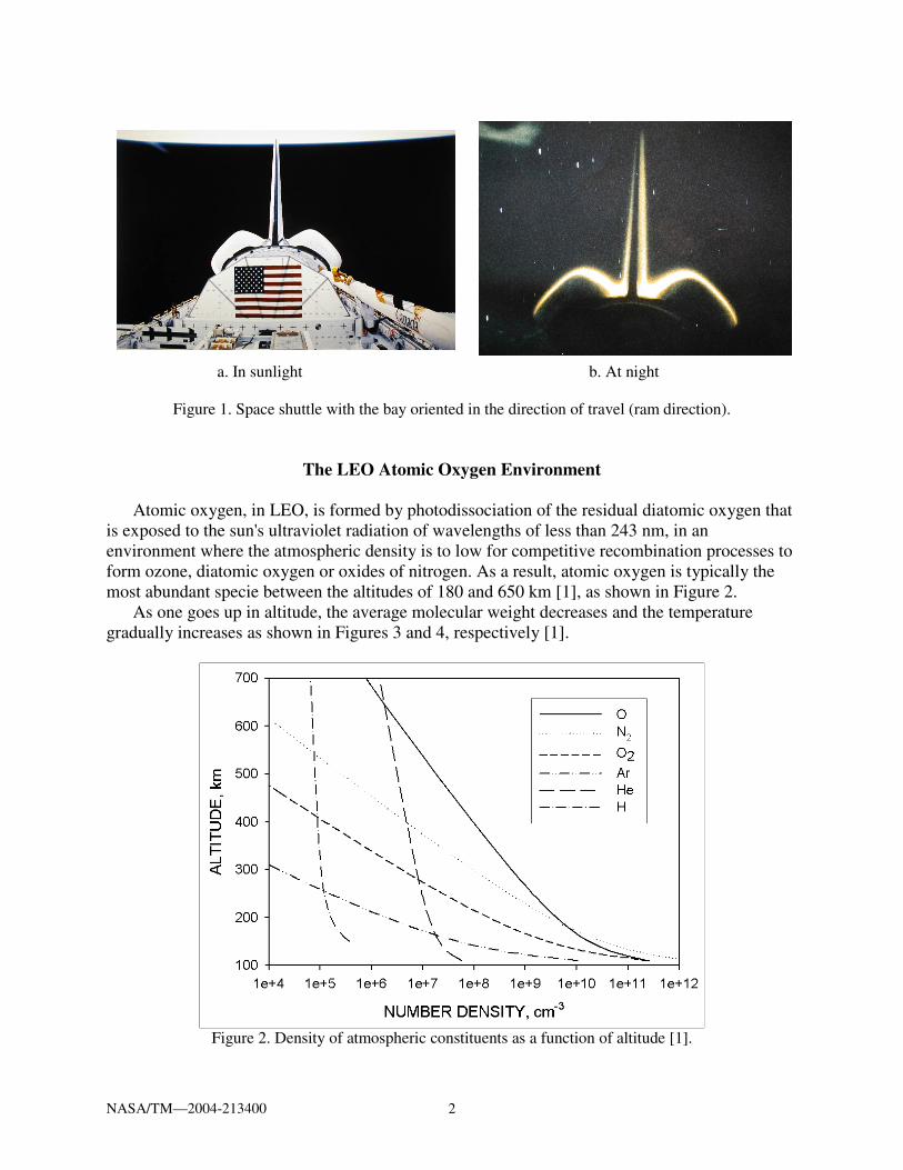
Early in-space observation that the residual atmosphere was interacting with spacecraft surfaces came in part as a result of comparison of day and night pictures of the space shuttle, as shown in Figure 1, where the glow from de-excitation atoms and molecules leaving shuttle surfaces oriented in the ram (forward facing) direction are shown [2 and 3]. A second indication of LEO atomic oxygen interactions came from observations of increases in the diffuse reflectance of polymers such as polyimide Kapton H due to surface texturing. Such observations lead to further tests which documented the rate of atomic oxygen erosion of commonly used spacecraft polymers, and resulting modifications to LEO spacecraft design in efforts to enable spacecraft to be durable to the LEO atomic oxygen environment.
This paper provides an overview of the LEO atomic oxygen environment, its interaction with spacecraft materials, approaches for protection from atomic oxygen, and on-orbit and computational results of protection methods.
NASA/TM—2004-213400 2
a. In sunlight b. At night
Figure 1. Space shuttle with the bay oriented in the direction of travel (ram direction).
The LEO Atomic Oxygen Environment
Atomic oxygen, in LEO, is formed by photodissociation of the residual diatomic oxygen that is exposed to the sun's ultraviolet radiation of wavelengths of less than 243 nm, in an environment where the atmospheric density is to low for competitive recombination processes to form ozone, diatomic oxygen or oxides of nitrogen. As a result, atomic oxygen is typically the most abundant specie between the altitudes of 180 and 650 km [1], as shown in Figure 2.
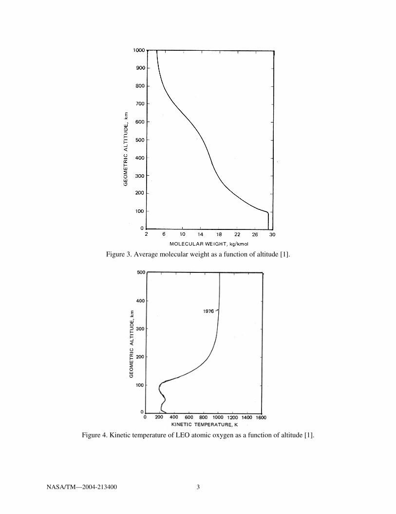
As one goes up in altitude, the average molecular weight decreases and the temperature gradually increases as shown in Figures 3 and 4, respectively [1].
Figure 2. Density of atmospheric constituents as a function of altitude [1].
NASA/TM—2004-213400 3
Figure 3. Average molecular weight as a function of altitude [1].
Figure 4. Kinetic temperature of LEO atomic oxygen as a function of altitude [1].

NASA/TM—2004-213400 4
The Earth's thermosphere co-rotates with the Earth giving atomic oxygen a velocity in the direction of the Earth's rotation. However, the orbital velocity of spacecraft is much greater and through most parts of an orbit is at an inclined angle to the equatorial plane. This orbital velocity vector, the Earth's co-rotation vector, and the random thermal velocity of the hot Maxwellian atomic oxygen gas causes a distribution of the arrival flux with angle of attack as well as a statistical variation in the energy atomic oxygen as it impacts spacecraft surfaces, as shown in Figures 5 and 6, respectively. Although Figure 6 is for circular orbits, highly inclined orbits would result in much greater impact energies.
Arrival angle relative to surface normal, degrees
0 5 10 15 20 25
Ato
mic
oxy
gen
flux
(par
alle
l to
the
Ear
th's
hor
izon
) re
lativ
e to
the
flux
at n
orm
al in
cide
nce
0.0
0.2
0.4
0.6
0.8
1.0
1.2
Figure 5. LEO atomic oxygen arrival flux versus arrival angle from ram direction for surfaces
perpendicular to the ram direction.
Figure 6. LEO Atomic oxygen energy versus orbital altitude for 28.5o inclined circular orbits.
NASA/TM—2004-213400 5
Organic Materials Interaction With Atomic Oxygen
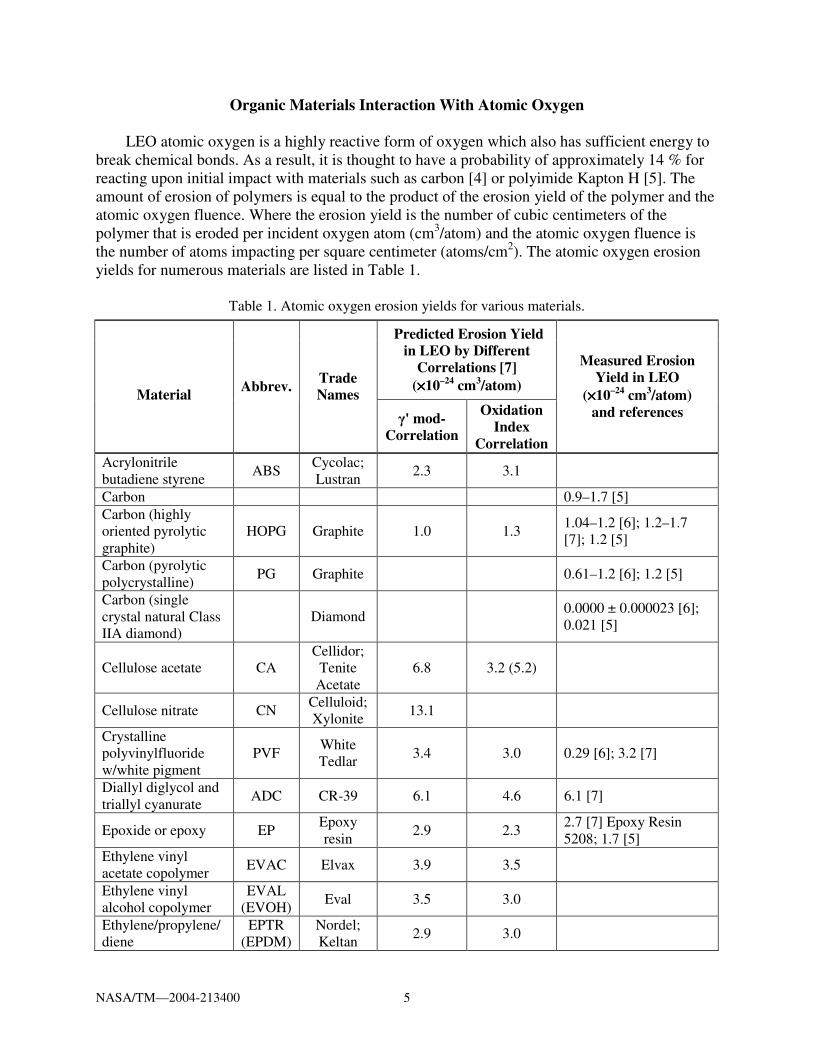
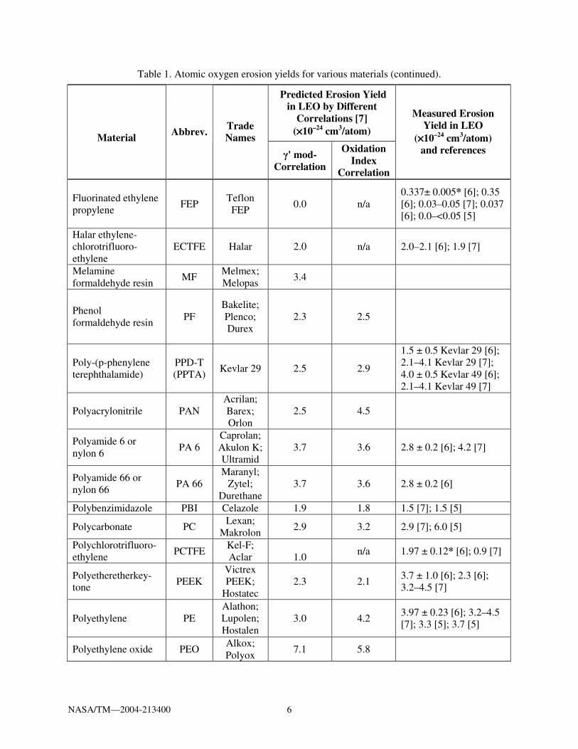
LEO atomic oxygen is a highly reactive form of oxygen which also has sufficient energy to break chemical bonds. As a result, it is thought to have a probability of approximately 14 % for reacting upon initial impact with materials such as carbon [4] or polyimide Kapton H [5]. The amount of erosion of polymers is equal to the product of the erosion yield of the polymer and the atomic oxygen fluence. Where the erosion yield is the number of cubic centimeters of the polymer that is eroded per incident oxygen atom (cm3/atom) and the atomic oxygen fluence is the number of atoms impacting per square centimeter (atoms/cm2). The atomic oxygen erosion yields for numerous materials are listed in Table 1.
Table 1. Atomic oxygen erosion yields for various materials.
Predicted Erosion Yield in LEO by Different
Correlations [7] (××××10–24 cm3/atom)
Material Abbrev. Trade Names
γ' mod-Correlation
Oxidation Index
Correlation
Measured Erosion Yield in LEO
(××××10–24 cm3/atom) and references
Acrylonitrile butadiene styrene
ABS Cycolac; Lustran
2.3 3.1
Carbon 0.9–1.7 [5] Carbon (highly oriented pyrolytic graphite)
HOPG Graphite 1.0 1.3 1.04–1.2 [6]; 1.2–1.7 [7]; 1.2 [5]
Carbon (pyrolytic polycrystalline)
PG Graphite 0.61–1.2 [6]; 1.2 [5]
Carbon (single crystal natural Class IIA diamond)
Diamond 0.0000 ± 0.000023 [6]; 0.021 [5]
Cellulose acetate CA Cellidor;
Tenite Acetate
6.8 3.2 (5.2)
Cellulose nitrate CN Celluloid; Xylonite
13.1
Crystalline polyvinylfluoride w/white pigment
PVF White Tedlar
3.4 3.0 0.29 [6]; 3.2 [7]
Diallyl diglycol and triallyl cyanurate
ADC CR-39 6.1 4.6 6.1 [7]
Epoxide or epoxy EP Epoxy resin
2.9 2.3 2.7 [7] Epoxy Resin 5208; 1.7 [5]
Ethylene vinyl acetate copolymer
EVAC Elvax 3.9 3.5
Ethylene vinyl alcohol copolymer
EVAL (EVOH)
Eval 3.5 3.0
Ethylene/propylene/diene
EPTR (EPDM)
Nordel; Keltan
2.9 3.0
NASA/TM—2004-213400 6
Table 1. Atomic oxygen erosion yields for various materials (continued).
Predicted Erosion Yield in LEO by Different
Correlations [7] (××××10–24 cm3/atom)
Material Abbrev. Trade Names
γ' mod-Correlation
Oxidation Index
Correlation
Measured Erosion Yield in LEO
(××××10–24 cm3/atom) and references
Fluorinated ethylene propylene
FEP Teflon FEP
0.0 n/a 0.337± 0.005* [6]; 0.35 [6]; 0.03–0.05 [7]; 0.037 [6]; 0.0–<0.05 [5]
Halar ethylene-chlorotrifluoro-ethylene
ECTFE Halar 2.0 n/a 2.0–2.1 [6]; 1.9 [7]
Melamine formaldehyde resin
MF Melmex; Melopas
3.4
Phenol formaldehyde resin
PF Bakelite; Plenco; Durex
2.3 2.5
Poly-(p-phenylene terephthalamide)
PPD-T (PPTA)
Kevlar 29 2.5 2.9
1.5 ± 0.5 Kevlar 29 [6]; 2.1–4.1 Kevlar 29 [7]; 4.0 ± 0.5 Kevlar 49 [6]; 2.1–4.1 Kevlar 49 [7]
Polyacrylonitrile PAN Acrilan; Barex; Orlon
2.5 4.5
Polyamide 6 or nylon 6
PA 6 Caprolan; Akulon K; Ultramid
3.7 3.6 2.8 ± 0.2 [6]; 4.2 [7]
Polyamide 66 or nylon 66
PA 66 Maranyl;
Zytel; Durethane
3.7 3.6 2.8 ± 0.2 [6]
Polybenzimidazole PBI Celazole 1.9 1.8 1.5 [7]; 1.5 [5]
Polycarbonate PC Lexan;
Makrolon 2.9 3.2 2.9 [7]; 6.0 [5]
Polychlorotrifluoro-ethylene
PCTFE Kel-F; Aclar 1.0
n/a 1.97 ± 0.12* [6]; 0.9 [7]
Polyetheretherkey-tone
PEEK Victrex PEEK;
Hostatec 2.3 2.1
3.7 ± 1.0 [6]; 2.3 [6]; 3.2–4.5 [7]
Polyethylene PE Alathon; Lupolen; Hostalen
3.0 4.2 3.97 ± 0.23 [6]; 3.2–4.5 [7]; 3.3 [5]; 3.7 [5]
Polyethylene oxide PEO Alkox; Polyox
7.1 5.8

NASA/TM—2004-213400 7
Table 1. Atomic oxygen erosion yields for various materials (continued).
Predicted Erosion Yield in LEO by Different
Correlations [7] (××××10–24 cm3/atom)
Material Abbrev. Trade Names
γ' mod-Correlatio
n
Oxidation Index
Correlation
Measured Erosion Yield in LEO
(××××10–24 cm3/atom) and references
Polyethylene terephthalate
PET Mylar; Tenite
3.5 3.1
3.4–3.6 Mylar A [6]; 3.4–3.7 Mylar A [5]; 3.0 Mylar D [6]; 2.9–3.0 Mylar D [5]; 3.4–3.9 [7]; 1.5–3.9 [5]
Polyimide (PMDA) PI Kapton HN 2.9 2.0 3.0 [7]; 3.0 [5]
Polyimide (PMDA) PI Kapton H 2.9 2.0 3.0 [6]; 2.89 ± 0.6 [6]; 3.0 [7]; 3.0 [5]; 1.5–3.1 [5]
Polyimide (PMDA) PI Black
Kapton 1.4–2.2 [5]
Polymethyl methacrylate
PMMA Plexiglas;
Lucite 5.1 4.5
6.3 ± 0.3 [6]; 3.9–4.8 [7]; 3.1 [5]
Polyoxymethylene; acetal; polyformaldehyde
POM Delrin; Celcon; Acetal
8.0–12.0 5.0
Polyphenylene PPH 1.8 Polyphenylene isophthalate
PPPA Nomex 2.5 2.9
Polypropylene PP Profax;
Propathene 2.9 4.1 4.4 [6]
Polystyrene PS Lustrex;
Polystyrol; Styron
2.1 6.0 4.17 ± 0.17 [6]; 1.8 [7]
Polysulphone (Polysulfone)
PSU Udel;
Ultrason/S 2.5 2.4–3.0 2.3 [6]; 2.1 [7]; 2.4 [5]
Polytetrafluoro-ethylene
PTFE Fluon; Teflon; Halon
0.0 n/a 0.20 [6]; 0.37 ± 0.06 [6]; 0.03–0.05 [7]; 0.0–0.2 [5]
Polyvinyl acetate PVA Elvacet 6.2 Polyvinyl alcohol PVA(L) Elvanol 7.1 4.1
Polyvinyl fluoride PVF Tedlar 3.8 clear [6]; 1.3–3.2 clear [5]; 0.05–0.6 white [5]
NASA/TM—2004-213400 8
Table 1. Atomic oxygen erosion yields for various materials (concluded).
Predicted Erosion Yield in LEO by Different
Correlations [7] (××××10–24 cm3/atom)
Material Abbrev. Trade Names
γ' mod-Correlation
Oxidation Index
Correlation
Measured Erosion Yield in LEO
(××××10–24 cm3/atom) and references
Polyvinylidene chloride copolymers
PVDC Saran 5.1 n/a
Polyvinylidene fluoride
PVDF Kynar 1.1 n/a 0.9–1.1 [7]; 0.6 [5]
Polyxylylene PX Parilene; Parylene
2.1
Pyrone PR Pyrone 2.4 2.3 [7]; 2.5 [5] Tetrafluorethylene-ethylene copolymer
ETFE Tefzel ZM 1.1 n/a 1.2 [7]
Urea formaldehyde UF Beetle; Avisco
5.1 3.0
* Corrected for LDEF ram fluence of 9.09×10²¹ atoms/cm2
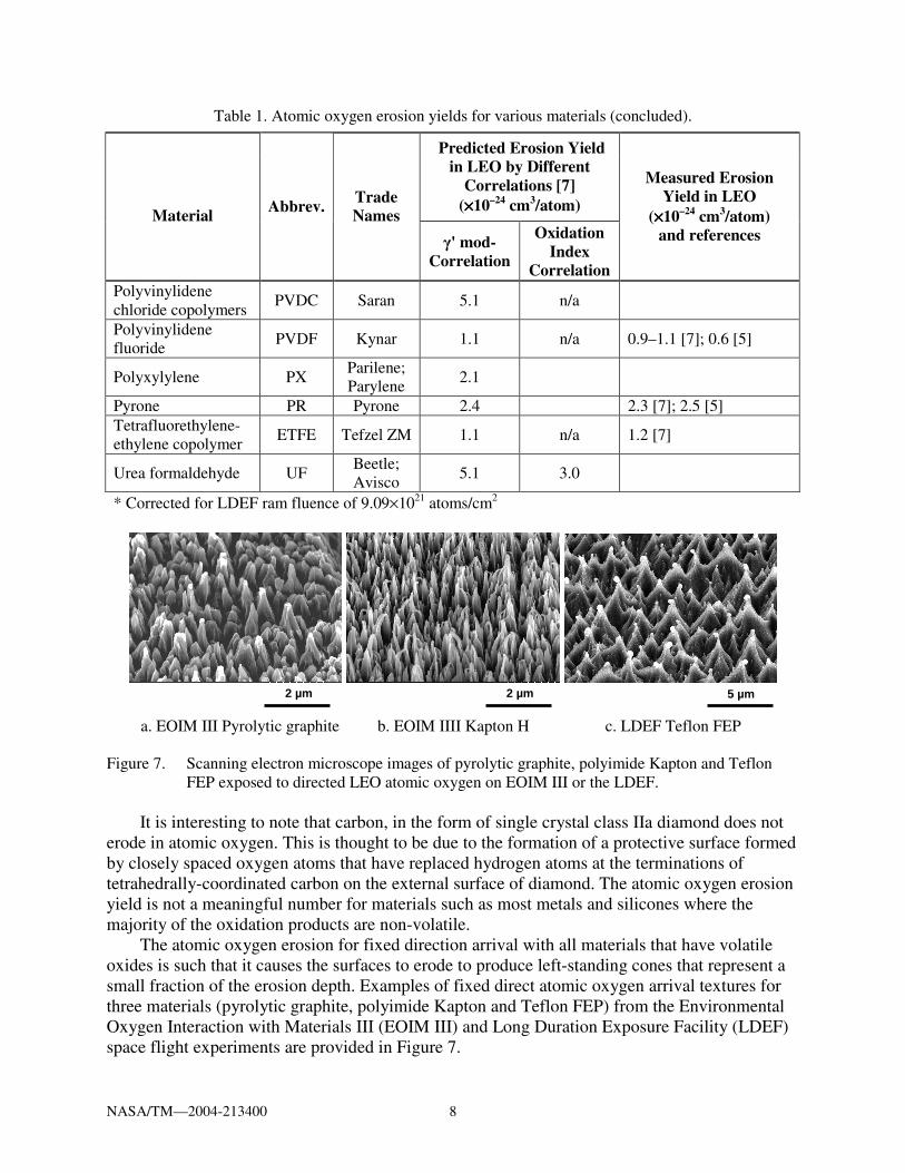
a. EOIM III Pyrolytic graphite b. EOIM IIII Kapton H c. LDEF Teflon FEP Figure 7. Scanning electron microscope images of pyrolytic graphite, polyimide Kapton and Teflon
FEP exposed to directed LEO atomic oxygen on EOIM III or the LDEF. It is interesting to note that carbon, in the form of single crystal class IIa diamond does not
erode in atomic oxygen. This is thought to be due to the formation of a protective surface formed by closely spaced oxygen atoms that have replaced hydrogen atoms at the terminations of tetrahedrally-coordinated carbon on the external surface of diamond. The atomic oxygen erosion yield is not a meaningful number for materials such as most metals and silicones where the majority of the oxidation products are non-volatile.
The atomic oxygen erosion for fixed direction arrival with all materials that have volatile oxides is such that it causes the surfaces to erode to produce left-standing cones that represent a small fraction of the erosion depth. Examples of fixed direct atomic oxygen arrival textures for three materials (pyrolytic graphite, polyimide Kapton and Teflon FEP) from the Environmental Oxygen Interaction with Materials III (EOIM III) and Long Duration Exposure Facility (LDEF) space flight experiments are provided in Figure 7.
2 µm 5 µm 2 µm

NASA/TM—2004-213400 9
The development of surface texture occurs whether or not the material is crystalline or amorphous and is a stochastic process which develops in a similar manner as to the meandering of rivers. Computational modeling of the surfaces also predicts the development of such surface cones [8 and 9]. Such surfaces have significant biomedical applications because they greatly increase cell attachment [8].
The length of cones increase with atomic oxygen fluence as the square root of the fluence [8]. The length of the cones relative to the average erosion depth for pyrolytic graphite, polyimide Kapton H and Teflon FEP are shown in Figure 8 at protected mesa locations. Calculated values for average cone height relative to the average erosion depth is provided in Table 2 for these flight samples, exposed at various atomic oxygen fluences on LDEF and EOIM III.
As can be seen in Table 2, the ratio of cone length to erosion depth appears to be material dependent. However, based on Reference 8, one would expect that for each material the ratio of cone length to erosion depth would decrease with atomic oxygen fluence.
a. EOIM III Pyrolytic graphite b. EOIM IIII Kapton H c. LDEF Teflon FEP Figure 8. Scanning electron microscope images at protected mesas of pyrolytic graphite, polyimide
Kapton and Teflon FEP exposed to directed LEO atomic oxygen on EOIM III or LDEF.
Table 2. Ratio of cone length to erosion depth as a function of fluence for various materials exposed to directed LEO atomic oxygen. Material Ratio of average cone
length to erosion depthSpace
Mission Atomic oxygen
fluence, atoms/cm2
Pyrolytic graphite 0.60 EOIM III 2.3×10²⁰ Kapton H 0.28 EOIM III 2.3×10²⁰ FEP Teflon 0.07 LDEF 8.43×10²¹
Protective Coatings
The rate of erosion of polymers such as polyimide Kapton is sufficiently high that protective coatings which are durable to atomic oxygen are typically applied to prevent or reduce the rate of attack of underlying polymers. Such coatings typically consist of metal oxide or metal thin films which are atomic oxygen durable and prevent atomic oxygen from reaching the underlying polymer. A protective coating of 1300 Angstroms of sputter deposited SiOx (where 1.9<x<2) have been applied to the International Space Station solar array Kapton H blankets. The
3 µm 5 µm 20 µm
NASA/TM—2004-213400 10
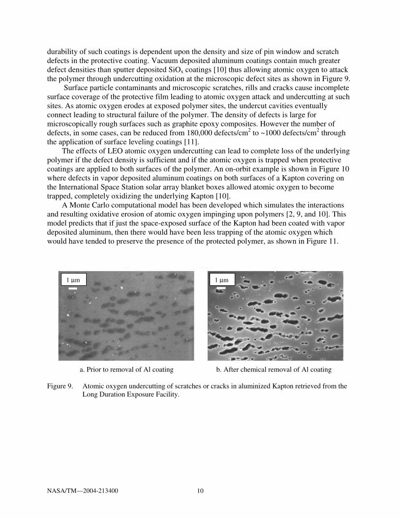
durability of such coatings is dependent upon the density and size of pin window and scratch defects in the protective coating. Vacuum deposited aluminum coatings contain much greater defect densities than sputter deposited SiOx coatings [10] thus allowing atomic oxygen to attack the polymer through undercutting oxidation at the microscopic defect sites as shown in Figure 9.
Surface particle contaminants and microscopic scratches, rills and cracks cause incomplete surface coverage of the protective film leading to atomic oxygen attack and undercutting at such sites. As atomic oxygen erodes at exposed polymer sites, the undercut cavities eventually connect leading to structural failure of the polymer. The density of defects is large for microscopically rough surfaces such as graphite epoxy composites. However the number of defects, in some cases, can be reduced from 180,000 defects/cm2 to ~1000 defects/cm2 through the application of surface leveling coatings [11].
The effects of LEO atomic oxygen undercutting can lead to complete loss of the underlying polymer if the defect density is sufficient and if the atomic oxygen is trapped when protective coatings are applied to both surfaces of the polymer. An on-orbit example is shown in Figure 10 where defects in vapor deposited aluminum coatings on both surfaces of a Kapton covering on the International Space Station solar array blanket boxes allowed atomic oxygen to become trapped, completely oxidizing the underlying Kapton [10].
A Monte Carlo computational model has been developed which simulates the interactions and resulting oxidative erosion of atomic oxygen impinging upon polymers [2, 9, and 10]. This model predicts that if just the space-exposed surface of the Kapton had been coated with vapor deposited aluminum, then there would have been less trapping of the atomic oxygen which would have tended to preserve the presence of the protected polymer, as shown in Figure 11.
a. Prior to removal of Al coating b. After chemical removal of Al coating Figure 9. Atomic oxygen undercutting of scratches or cracks in aluminized Kapton retrieved from the
Long Duration Exposure Facility.
1 µm 1 µm

NASA/TM—2004-213400 11
a. ISS solar array blanket box. b. Close-up of damage. Figure 10. International Space Station solar array blanket box after one year in LEO showing only the
vacuum deposited aluminum coatings are present after complete oxidation of the underlying Kapton [10].
a. Prediction for protective coatings on both sides of the underlying Kapton.
b. Prediction for a protective coating on only the space exposed side of the underlying Kapton.
Figure 11. Computational model predictions for protective coatings on either both sides of the
underlying Kapton or on only the space exposed side of the underlying Kapton.
Summary
Atomic oxygen formed in low Earth orbit, has sufficient energy and flux to oxidize and erode most hydrocarbon polymers. There is a distribution in atomic oxygen arrival angle of attack caused by the orbital inclination, the Earth's co-rotation and the random thermal velocity of the hot Maxwellian atomic oxygen gas. The spatially random erosion processes causes the surfaces of all materials that have volatile oxidation products to become microscopically rough with cone structures that point in the direction of arriving atoms.
Atomic oxygen protective coatings of metal oxides and metals is a valuable means of reducing oxidative attack. However, microscopic particle contaminants, scratches, rills and cracks cause incomplete surface coverage of the protective film leading to atomic oxygen attack and undercutting at such sites. For this reason, coating only the atomic oxygen exposed side of a

NASA/TM—2004-213400 12
hydrocarbon polymer is desirable to prevent trapped atomic oxygen from severely undercutting the polymer substrate. The use of metal oxide protective coatings and surface leveling coatings can greatly reduce the density of defects in comparison to aluminized protective coatings.
References 1. NOAA, NASA and USAF, U.S. Standard Atmosphere, 1976, NASA TMX–74335, 1976. 2. Banks, B.A., de Groh, K.K., Rutledge, S.K., DiFilippo, F.J., “Prediction of In-Space
Durability of Protected Polymers Based on Ground Laboratory Thermal Energy Atomic Oxygen,” paper presented at the Third International Space Conference, Toronto, Canada, April 25–26, 1996.
3. Mende, S.B. Swenson, G.R., Clifton, K.S., Science, Vol. 225:191, 1984. 4. Banks, B.A., Rutledge S.K., “Low Earth Orbital Atomic Oxygen Simulation for Materials
Durability Evaluation,” Fourth European Symposium on Spacecraft Materials in Space Environment, Toulouse, France, 6–9, September, 1988, pp. 372–392, 10.
5. Bruce A. Banks, S.K. Rutledge, Phillip E. Paulsen and Thomas J. Steuber, “Simulation of the Low Earth Orbital Atomic Oxygen Interaction With Materials by Means of an Oxygen Ion Beam,” Presented at the 18th Annual Symposium on Applied Vacuum Science and Technology, Clearwater Beach, Florida, February 6–8, 1989; NASA TM–101971, 1989.
6. Bruce A. Banks, “The Use of Fluoropolymers in Space Applications” in Modern Fluoropolymers, Edited by John Scheirs, (pp. 103–113), Chapter 4, John Wiley & Sons Ltd, 1997.
7. “Prediction of Erosion of Polymer-Based Materials by Atomic Oxygen in LEO,” Integrity Testing Laboratory Inc. Final Report, GRC Contract #C–72917–G, 1998.
8. Banks, B.A., Rutledge, S.K., Chan, A., Sahota, M., “The Development of Surface Roughness and Implications for Cellular Attachment in Biomedical Applications,” NASA/TM—2001-211288, presented at the 2001 Fall Meeting of the Materials Research Society, Boston, MA, November 26–30, 2001.
9. Banks, B.A., Stueber, T.J., Snyder, S.A., Rutledge, S.K., and Norris, M.J., “Atomic Oxygen Erosion Phenomena,” presented at the American Institute of Aeronautics and Astronautics, Defense and Space Programs Conference, Huntsville, AL, Sept. 23–25, 1997.
10. Banks, B., Lenczewski, M., and Demko, R., “Durability Issues for the Protection of Materials from Atomic Oxygen Attack in Low Earth Orbit,” NASA/TM—2002-211830, August 2002, Paper IAC–02–1.5.02, presented at the 53 International Astronautical Congress, The World Space Congress—2002, Houston TX, October 10–19, 2002.
11. D.A. Jaworske, K.K. de Groh, G. Podojil, T. McCollum, and J. Anzic, “Leveling Coatings for Reducing the Atomic Oxygen Defect Density in Protected Graphite Fiber Epoxy Composites,” Journal of the IES (Institute of Environmental Sciences), May/June 1994, Vol. XXXVII, No. 3, pp. 26–31.
This publication is available from the NASA Center for AeroSpace Information, 301–621–0390.
REPORT DOCUMENTATION PAGE
2. REPORT DATE
19. SECURITY CLASSIFICATION OF ABSTRACT
18. SECURITY CLASSIFICATION OF THIS PAGE
Public reporting burden for this collection of information is estimated to average 1 hour per response, including the time for reviewing instructions, searching existing data sources,gathering and maintaining the data needed, and completing and reviewing the collection of information. Send comments regarding this burden estimate or any other aspect of thiscollection of information, including suggestions for reducing this burden, to Washington Headquarters Services, Directorate for Information Operations and Reports, 1215 JeffersonDavis Highway, Suite 1204, Arlington, VA 22202-4302, and to the Office of Management and Budget, Paperwork Reduction Project (0704-0188), Washington, DC 20503.
NSN 7540-01-280-5500 Standard Form 298 (Rev. 2-89)Prescribed by ANSI Std. Z39-18298-102
Form ApprovedOMB No. 0704-0188
12b. DISTRIBUTION CODE
8. PERFORMING ORGANIZATION REPORT NUMBER
5. FUNDING NUMBERS
3. REPORT TYPE AND DATES COVERED
4. TITLE AND SUBTITLE
6. AUTHOR(S)
7. PERFORMING ORGANIZATION NAME(S) AND ADDRESS(ES)
11. SUPPLEMENTARY NOTES
12a. DISTRIBUTION/AVAILABILITY STATEMENT
13. ABSTRACT (Maximum 200 words)
14. SUBJECT TERMS
17. SECURITY CLASSIFICATION OF REPORT
16. PRICE CODE
15. NUMBER OF PAGES
20. LIMITATION OF ABSTRACT
Unclassified Unclassified
Technical Memorandum
Unclassified
National Aeronautics and Space AdministrationJohn H. Glenn Research Center at Lewis FieldCleveland, Ohio 44135–3191
1. AGENCY USE ONLY (Leave blank)
10. SPONSORING/MONITORING AGENCY REPORT NUMBER
9. SPONSORING/MONITORING AGENCY NAME(S) AND ADDRESS(ES)
National Aeronautics and Space AdministrationWashington, DC 20546–0001
Available electronically at http://gltrs.grc.nasa.gov
November 2004
NASA TM—2004-213400
E–14905
WBS–22–090–20–C3
18
Low Earth Orbital Atomic Oxygen Interactions With Spacecraft Materials
Bruce A. Banks, Kim K. de Groh, and Sharon K. Miller
Atomic oxygen; low Earth orbit; Erosion yield
Unclassified -UnlimitedSubject Category: 31 Distribution: Nonstandard
Prepared for the 2004 Fall Meeting sponsored by the Materials Research Society, Boston, Massachusetts,November 29–December 3, 2004. Responsible person, Bruce A. Banks, organization code RPY, 216–433–2308.
Atomic oxygen, formed in Earth’s thermosphere, interacts readily with many materials on spacecraft flying in low Earthorbit (LEO). All hydrocarbon based polymers and graphite are easily oxidized upon the impact of ~4.5 eV atomicoxygen as the spacecraft ram into the residual atmosphere. The resulting interactions can change the morphology andreduce the thickness of these materials. Directed atomic oxygen erosion will result in the development of texturedsurfaces on all materials with volatile oxidation products. Examples from space flight samples are provided. As a resultof the erosive properties of atomic oxygen on polymers and composites, protective coatings have been developed and areused to increase the functional life of polymer films and composites that are exposed to the LEO environment. Theatomic oxygen erosion yields for actual and predicted LEO exposure of numerous materials are presented. Results ofin-space exposure of vacuum deposited aluminum protective coatings on polyimide Kapton indicate high rates ofdegradation are associated with aluminum coatings on both surfaces of the Kapton. Computational modeling predictionsindicate that less trapping of the atomic oxygen occurs, with less resulting damage, if only the space-exposed surface iscoated with vapor deposited aluminum rather than having both surfaces coated.


![Low Earth Orbital Atomic Oxygen Interactions With ... › api › citations › 20040191331 › downloads › 20040191331.pdfPolycarbonate PC Lexan; Makrolon 2.9 3.2 2.9 [7]; 6.0 [5]](https://img.pdfslide.net/doc/110x75/60c0be5d90c08949214e7445/low-earth-orbital-atomic-oxygen-interactions-with-a-api-a-citations-a.jpg)