Embed Size (px)
Citation preview
http://www.iaeme.com/IJMET/index.asp 244 [email protected]
International Journal of Mechanical Engineering and Technology (IJMET)
Volume 7, Issue 2, March-April 2016, pp. 244–260, Article ID: IJMET_07_02_026
Available online at
http://www.iaeme.com/IJMET/issues.asp?JType=IJMET&VType=7&IType=2
Journal Impact Factor (2016): 9.2286 (Calculated by GISI) www.jifactor.com
ISSN Print: 0976-6340 and ISSN Online: 0976-6359
© IAEME Publication
LOW EXPENSE VERTICAL AXIS WIND
TURBINE USING PERMANENT MAGNETS
Ramu S
Assistant Professor
Sree Narayana Institute of Technology, Adoor, Kerala
Abhilash M, Ajay M, Aravind S, Hariprasad M
Students, Sree Narayana Institute of Technology,
Adoor, Kerala
ABSTRACT
Wind turbines are devices that convert the wind's kinetic energy into
electrical power. The result of over a millennium of windmill development and
modern engineering, today's wind turbines are manufactured in a wide range
of horizontal axis and vertical axis types. The smallest turbines are used for
applications such as battery charging for auxiliary power. Slightly larger
turbines can be used for making small contributions to a domestic power
supply while selling unused power back to the utility supplier via the electrical
grid. Arrays of large turbines, known as wind farms, have become an
increasingly important source of renewable energy and are used in many
countries as part of a strategy to reduce their reliance on fossil fuels.
Key word: Design, Material Selection, Modelling, Analysis
Cite this Article Ramu S, Abhilash M, Ajay M, Aravind S and Hariprasad M,
Low Expense Vertical Axis Wind Turbine Using Permanent Magnets.
International Journal of Mechanical Engineering and Technology, 7(2), 2016,
pp. 244–260.
http://www.iaeme.com/currentissue.asp?JType=IJMET&VType=7&IType=2
1. INTRODUCTION
When If the efficiency of a wind turbine is increased, then more power can be
generated thus decreasing the need for expensive power generators that cause
pollution. This would also reduce the cost of power for the common people. The wind
is literally there for the taking and doesn't cost any money. Power can be generated
and stored by a wind turbine with little or no pollution. If the efficiency of the
common wind turbine is improved and widespread, the common people can cut back
on their power costs immensely. Ever since the Seventh Century people have been
utilizing the wind to make their lives easier. Windmills have 5-6 blades. While past
windmills have had 48 blades. Past windmill also had to be manually directed into the
Low Expense Vertical Axis Wind Turbine Using Permanent Magnets
http://www.iaeme.com/IJMET/index.asp 245 [email protected]
wind, while modern windmills can be automatically turned into the wind. The sail
design and materials used to create them have also changed over the years. In most
cases the altitude of the rotor is directly proportional to its efficiency. As a matter of
fact, a modern wind turbine should be at least twenty feet above from an obstruction,
though it is even more ideal for it to be thirty feet above and five hundred feet away
from any obstruction. Different locations have various wind speeds. Some places,
such as the British Isles, have few inhabitants because of high wind speeds, yet they
are ideal for wind generation. Some geographic features such as mountains also have
an influence upon wind. Mountains can create mountain breezes at night, because of
the cooler air owing down the mountain and being heated by the warmer valley air
causing a convection current. Valleys are affected in much the same way. In the
daytime, the cooler air is above the valleys and the hot air is above the mountains. The
hot air above the mountain rises above the valleys and cools, thus creating a
convection current in the opposite direction and creating a valley wind. The oceans
create convection currents, as well as they mountains or valleys. In the day, the hotter
air is above the same and the cooler air is above the ocean. The air heats up over the
sand and rises above the ocean and then cools, creating the convection current. At
night, the cooler air is above the sand and the warmer air is above the ocean, so the air
heats up over the ocean and cools over the sand. Actually there are two types of
windmills (the horizontal axis windmills and the vertical axis windmills). The
horizontal axis windmills have a horizontal rotor much like the classic Dutch four-arm
wind-mill. The horizontal axis windmills primarily rely on lift from the wind. As
stated in Bernoulli's Principle, "a fluid will travel from an area of higher pressure to
an area of lower pressure. It also states, "As the velocity of a fluid increases, its
density decreases." Based upon this principle, horizontal axis windmill blades have
been designed much like the wings of an airplane, with a curved top. This design
increases the velocity of the air on top of the blade thus decreasing its density and
causing the air on the bottom of the blade to go towards the top. Creating lift .The
blades are angled on the axis as to utilize the lift in the rotation. The blades on modern
wind turbines are designed for maximum lift and minimal drag. Vertical axis
windmills, such as the Durries (built in 1930) use drag instead of lift. Drag is
resistance to the wind, like a brick wall. The blades on vertical axis windmills are
designed to give resistance to the wind and are as a result pushed by the wind. There
have been many improvements to the windmill over the years. Windmills have been
equipped with air breaks, to control speed in strong winds. Some vertical axis
windmills have even been equipped with hinged blades to avoid the stresses at high
wind speeds. Some windmills, like the cyclo- turbine, have been equipped with a vane
that senses wind direction and causes the rotor to rotate into the wind. Wind turbine
generators have been equipped with gearboxes to control [shaft] speeds. Wind
turbines have also been equipped with generators which convert shaft power into
electrical power. Many of the sails on windmills have also been replaced with
propeller- like aerofoils. Some windmills can also stall in the wind to control wind
speed. But above all of these improvements, the most important improvement to the
windmill was made in 1745 when the fantail was invented. The fantail automatically
rotates the sails into the wind. Most wind turbines start to generate power at 11 m/s
and shut down at speeds near 32m/s. Another variable of the windmill's efficiency is
its swept area. The swept area of a disc shaped wind wheel is calculated as: Area
equals pi times diameter squared divided by four (pi equals 3.14).Another variable in
the productivity of a windmill is the wind speed. The wind speed is measured by an
anemometer. Another necessity for a windmill is the tower. There are many types of
Ramu S, Abhilash M, Ajay M, Aravind S and Hariprasad M
http://www.iaeme.com/IJMET/index.asp 246 [email protected]
towers. Some towers have guy wire to support them and others don't. The towers
without guy wires are called freestanding towers. Something to take into
consideration about a tower is that it must support the weight of the windmill along
with the weight of the tower.
2. SCOPE OF WORK
To utilize the available wind resources and to reduce the usage of non-renewable
energy resources. Wind energy is by far the fastest-growing renewable energy
resource. The wind energy industry so far has been supported by market incentives
backed by government policies fostering sustainable energy resources. Large-scale
wind facilities approaching the output rating of conventional power plants, control of
the power quality is required to reduce the adverse effects on their integration into the
network. These wind turbines can be used to provide constant lighting. Building’s
rooftops can be an excellent location for this type of wind mill, both because the
electric power generation is close to the user and because they allow taking
advantages of faster winds and also it is possible for generating power in rural areas
and hilly tops where electric transmission lines are difficult to reach. It can be
installed in more locations like highways, in parking areas etc.
3. LITERATURE REVIEW
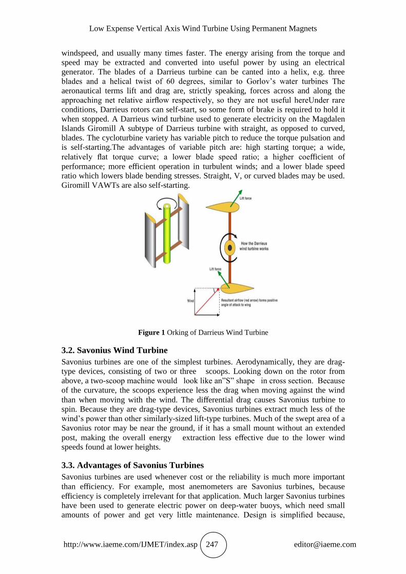
The forces and the velocities acting in a Darrieus turbine are depicted. The resultant
velocity vector W, is the vectorial sum of the undisturbed upstream air velocity U, and
the velocity vector of the advancing blade. Types of vertical axis wind turbines are as
follows.
3.1. Darrieus Wind Turbine
Commonly described as “Eggbeater” turbines, or Darrieus turbines, were named after
the French inventor, Georges Darrieus. They have good efficiency, but produce large
torque ripple and cyclical stress on the tower, which contributes to poor reliability.
They also generally require some external power source, or an additional Savonius
rotor to start turning, because the starting torque is very low. The torque ripple is
reduced by using three or more blades which results in greater solidity of the rotor.
Solidity is measured by blade area divided by the rotor area. Newer Darrieus type
turbines are not held up by guy-wires but have an external superstructure connected to
the top bearing. The Darrieus design, the aerofoils are arranged so that they are
symmetrical and have zero rigging angle, that is, the angle that the aerofoils are set
relative to the structure on which they are mounted. This arrangement is equally
effective no matter which direction the wind is blowingin contrast to the conventional
type, which must be rotated to face into the wind. When the Darrieus rotor is
spinning, the aerofoils are moving forward through the air in a circular path. Relative
to the blade, this oncoming airflow is added vectorially to the wind, so that the
resultant airflow creates a varying small positive angle of attack to the blade. This
generates a net force pointing obliquely forwards along a certain ’line-of- action’.
This force can be projected inwards past the turbine axis at a certain distance, giving a
positive torque to the shaft, thus helping it to rotate in the direction it is already
travelling in. The aerodynamic principles which rotate the rotor are equivalent to that
in autogiros, and normal helicopters in autorotation. As the aerofoil moves around the
back of the apparatus, the angle of attack changes to the opposite sign, but the
generated force is still obliquely in the direction of rotation, because the wings are
symmetrical and the rigging angle is zero. The rotor spins at a rate unrelated to the
Low Expense Vertical Axis Wind Turbine Using Permanent Magnets
http://www.iaeme.com/IJMET/index.asp 247 [email protected]
windspeed, and usually many times faster. The energy arising from the torque and
speed may be extracted and converted into useful power by using an electrical
generator. The blades of a Darrieus turbine can be canted into a helix, e.g. three
blades and a helical twist of 60 degrees, similar to Gorlov’s water turbines The
aeronautical terms lift and drag are, strictly speaking, forces across and along the
approaching net relative airflow respectively, so they are not useful hereUnder rare
conditions, Darrieus rotors can self-start, so some form of brake is required to hold it
when stopped. A Darrieus wind turbine used to generate electricity on the Magdalen
Islands Giromill A subtype of Darrieus turbine with straight, as opposed to curved,
blades. The cycloturbine variety has variable pitch to reduce the torque pulsation and
is self-starting.The advantages of variable pitch are: high starting torque; a wide,
relatively flat torque curve; a lower blade speed ratio; a higher coefficient of
performance; more efficient operation in turbulent winds; and a lower blade speed
ratio which lowers blade bending stresses. Straight, V, or curved blades may be used.
Giromill VAWTs are also self-starting.
Figure 1 Orking of Darrieus Wind Turbine
3.2. Savonius Wind Turbine
Savonius turbines are one of the simplest turbines. Aerodynamically, they are drag-
type devices, consisting of two or three scoops. Looking down on the rotor from
above, a two-scoop machine would look like an”S” shape in cross section. Because
of the curvature, the scoops experience less the drag when moving against the wind
than when moving with the wind. The differential drag causes Savonius turbine to
spin. Because they are drag-type devices, Savonius turbines extract much less of the
wind’s power than other similarly-sized lift-type turbines. Much of the swept area of a
Savonius rotor may be near the ground, if it has a small mount without an extended
post, making the overall energy extraction less effective due to the lower wind
speeds found at lower heights.
3.3. Advantages of Savonius Turbines
Savonius turbines are used whenever cost or the reliability is much more important
than efficiency. For example, most anemometers are Savonius turbines, because
efficiency is completely irrelevant for that application. Much larger Savonius turbines
have been used to generate electric power on deep-water buoys, which need small
amounts of power and get very little maintenance. Design is simplified because,
Ramu S, Abhilash M, Ajay M, Aravind S and Hariprasad M
http://www.iaeme.com/IJMET/index.asp 248 [email protected]
unlike with Horizontal Axis Wind Turbines (HAWTs), no pointing mechanism is
required to allow for shifting wind direction and the turbine is self-starting. They can
sometimes have long helical scoops, to give smooth torque. The most ubiquitous
application of the Savonius wind turbine is the Flettner Ventilator which is commonly
seen on the roofs of vans and buses and is used as a cooling device. The ventilator
was developed by the German aircraft engineer Anton Flettner in the 1920s. It uses
the Savonius wind turbine to drive an extractor fan. The vents are still manufactured
in the UK by Flettner Ventilator Limited Small Savonius wind turbines are sometimes
seen used as advertising signs where the rotation helps to draw attention to the item
advertised. They sometimes feature a simple two- frame animation.
4. CHARACTERSTICS AND SPECIFICATIONS OF WIND
TURBINES
The Source of Winds
In a macro-meteorological sense, winds are movements of air masses in the
atmosphere mainly originated by temperature differences. The temperature gradients
are due to uneven solar heating. In fact, the equatorial region is more irradiated than
the polar ones. Consequently, the warm and lighter air of the equatorial region rises
to the outer layers of the atmosphere and moves towards the poles, being replaced at
the lower layers by a return flow of cooler air coming from the Polar Regions. This air
circulation is also affected by the Coriolis forces associated with the rotation of the
Earth. In fact, these forces defect the upper flow towards the east and the lower flow
towards the west. Actually, the effects of differential heating dwindle for latitudes
greater than 30ºN and 30ºS, where westerly winds predominate due to the rotation of
the Earth. These large-scale air flows that take place in all the atmosphere constitute
the geostrophic winds. The lower layer of the atmosphere is known as surface layer
and extends to a height of 100 m. In this layer, winds are delayed by frictional forces
and obstacles altering not only their speed but also their direction. This is the origin of
turbulent flows, which cause wind speed variations over a wide range of amplitudes
and frequencies. Additionally, the presence of seas and large lakes causes air masses
circulation similar in nature to the geostrophic winds. All these air movements are
called local winds.
4.1. The Power of Wind
The power in the wind can be computed by using the concepts of kinetics. The wind
mill works on the principle of converting kinetic energy of the wind to mechanical
energy. The kinetic energy of any particle is equal to one half its mass times the
square of its velocity.
4.2. Wind Speed
This is very important to the productivity of a windmill. The wind turbine only
generates power with the wind. The wind rotates the axis (horizontal or vertical) and
causes the shaft on the generator to sweep past the magnetic coils creating an electric
current.
Low Expense Vertical Axis Wind Turbine Using Permanent Magnets
http://www.iaeme.com/IJMET/index.asp 249 [email protected]
4.3. Blade Length
This is important because the length of the blade is directly proportional to the swept
area. Larger blades have a greater swept area and thus catch more wind with each
revolution. Because of this, they may also have more torque
4.4. Base height
The height of the base affects the windmill immensely. The higher a windmill is, the
more productive it will be due to the fact that as the altitude increases so does the
winds speed.
4.5. Base Design
Some base is stronger than others. Base is important in the construction of the
windmill because not only do they have to support the windmill, but they must also be
subject to their own weight and the drag of the wind. If a weak tower is subject to
these elements, then it will surely collapse. Therefore, the base must be identical so as
to insure a fair comparison.
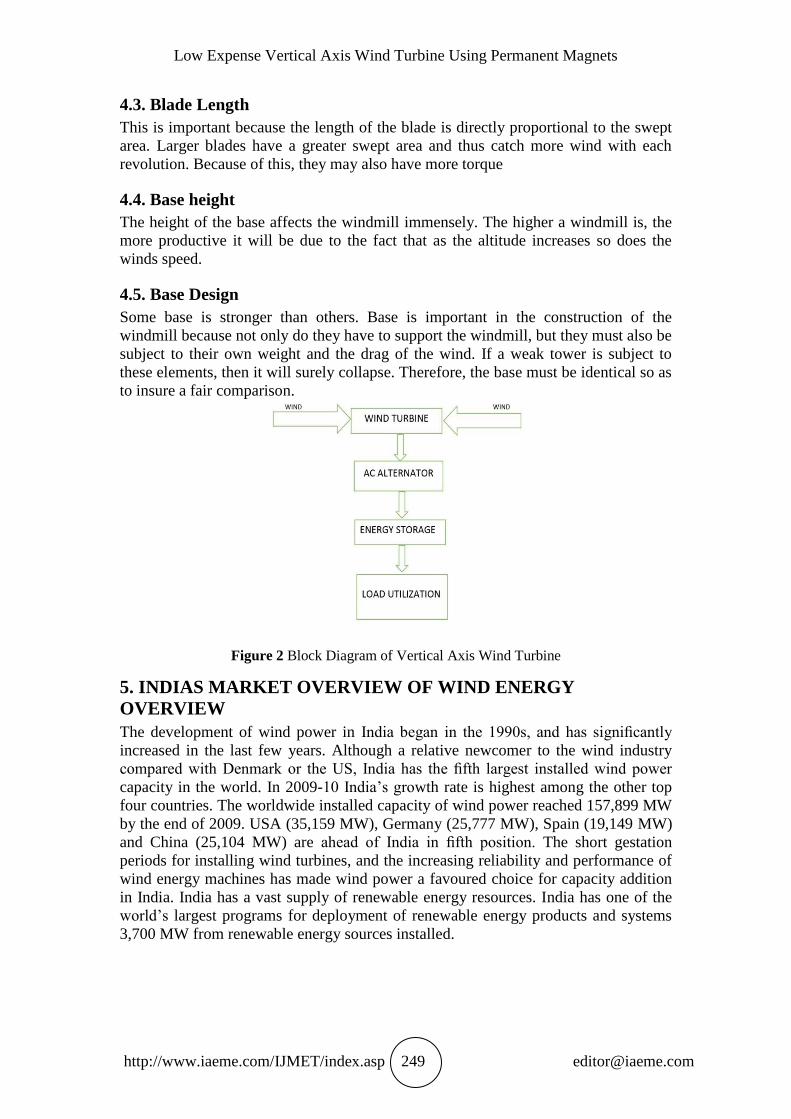
Figure 2 Block Diagram of Vertical Axis Wind Turbine
5. INDIAS MARKET OVERVIEW OF WIND ENERGY
OVERVIEW
The development of wind power in India began in the 1990s, and has significantly
increased in the last few years. Although a relative newcomer to the wind industry
compared with Denmark or the US, India has the fifth largest installed wind power
capacity in the world. In 2009-10 India’s growth rate is highest among the other top
four countries. The worldwide installed capacity of wind power reached 157,899 MW
by the end of 2009. USA (35,159 MW), Germany (25,777 MW), Spain (19,149 MW)
and China (25,104 MW) are ahead of India in fifth position. The short gestation
periods for installing wind turbines, and the increasing reliability and performance of
wind energy machines has made wind power a favoured choice for capacity addition
in India. India has a vast supply of renewable energy resources. India has one of the
world’s largest programs for deployment of renewable energy products and systems
3,700 MW from renewable energy sources installed.
Ramu S, Abhilash M, Ajay M, Aravind S and Hariprasad M
http://www.iaeme.com/IJMET/index.asp 250 [email protected]
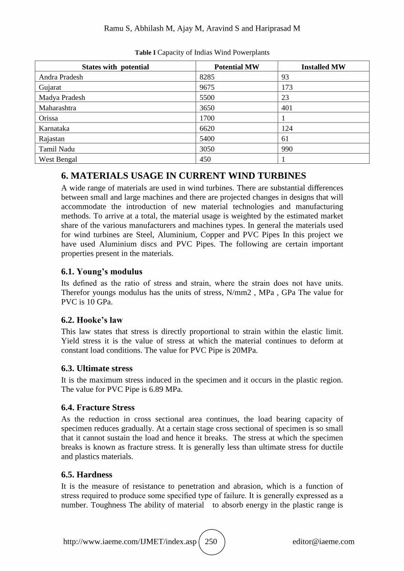
Table I Capacity of Indias Wind Powerplants
States with potential Potential MW Installed MW
Andra Pradesh 8285 93
Gujarat 9675 173
Madya Pradesh 5500 23
Maharashtra 3650 401
Orissa 1700 1
Karnataka 6620 124
Rajastan 5400 61
Tamil Nadu 3050 990
West Bengal 450 1
6. MATERIALS USAGE IN CURRENT WIND TURBINES
A wide range of materials are used in wind turbines. There are substantial differences
between small and large machines and there are projected changes in designs that will
accommodate the introduction of new material technologies and manufacturing
methods. To arrive at a total, the material usage is weighted by the estimated market
share of the various manufacturers and machines types. In general the materials used
for wind turbines are Steel, Aluminium, Copper and PVC Pipes In this project we
have used Aluminium discs and PVC Pipes. The following are certain important
properties present in the materials.
6.1. Young’s modulus
Its defined as the ratio of stress and strain, where the strain does not have units.
Therefor youngs modulus has the units of stress, N/mm2 , MPa , GPa The value for
PVC is 10 GPa.
6.2. Hooke’s law
This law states that stress is directly proportional to strain within the elastic limit.
Yield stress it is the value of stress at which the material continues to deform at
constant load conditions. The value for PVC Pipe is 20MPa.
6.3. Ultimate stress
It is the maximum stress induced in the specimen and it occurs in the plastic region.
The value for PVC Pipe is 6.89 MPa.
6.4. Fracture Stress
As the reduction in cross sectional area continues, the load bearing capacity of
specimen reduces gradually. At a certain stage cross sectional of specimen is so small
that it cannot sustain the load and hence it breaks. The stress at which the specimen
breaks is known as fracture stress. It is generally less than ultimate stress for ductile
and plastics materials.
6.5. Hardness
It is the measure of resistance to penetration and abrasion, which is a function of
stress required to produce some specified type of failure. It is generally expressed as a
number. Toughness The ability of material to absorb energy in the plastic range is
Low Expense Vertical Axis Wind Turbine Using Permanent Magnets
http://www.iaeme.com/IJMET/index.asp 251 [email protected]
known as toughness. Toughness per unit volume of the material is known as modulus
of toughness.
7. PRINCIPLE OF GENERATOR OPERATION
7.1. Generator
The generator uses rotating coils of wire and magnetic fields to convert mechanical
rotation into a pulsing direct electric current through Faraday’s law of induction. A
dynamo machine consists of a stationary structure, called the stator, which provides a
constant magnetic field, and a rotating winding called armature which turn within that
field. The motion of the wire within the magnetic field causes the field to push on the
electrons in the metal, creating an electric current in the wire. On small machines
constant magnetic field may be provided by one or more permanent magnets; larger
machines have constant the magnetic field provided by one or more electromagnets,
which are usually called field coils. The commutator was needed to produce direct
current. When a loop wire rotates in a magnetic field, the potential induced in it
reverses with each half turn generating an alternating current. However, in early days
of electric experimentation, alternating current generally no known use. The few uses
for electricity, such as electroplating, used direct current provided by messy liquid
batteries. The generation of electricity by a dynamo is based on a principle of
magnetism called induction. When the lines of force that pass from the north to the
south pole of a magnet are cut by a wire there is produced or induced in the wire a
current of electricity. That is, if we take a loop or coil of wire which has no current in
it and a magnet which also has no current, and move the loop or coil between the
poles, a momentary current is produced. If a series of loops or coils are used instead
of one loop, a current may be generated continuously. This method of generating
electric current is called induction.
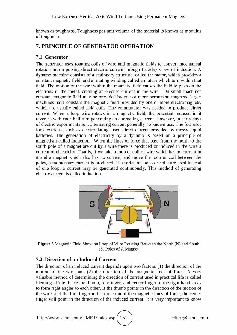
Figure 3 Magnetic Field Showing Loop of Wire Rotating Between the North (N) and South
(S) Poles of A Magnet
7.2. Direction of an Induced Current
The direction of an induced current depends upon two factors: (1) the direction of the
motion of the wire, and (2) the direction of the magnetic lines of force. A very
valuable method of determining the direction of current used in practical life is called
Fleming's Rule. Place the thumb, forefinger, and center finger of the right hand so as
to form right angles to each other. If the thumb points in the direction of the motion of
the wire, and the fore finger in the direction of the magnetic lines of force, the center
finger will point in the direction of the induced current. It is very important to know
Ramu S, Abhilash M, Ajay M, Aravind S and Hariprasad M
http://www.iaeme.com/IJMET/index.asp 252 [email protected]
the direction of the current in revolving a loop of wire between the poles of a magnet
in order to understand the working of a generator. The loop of wire between the poles
of the magnet. If the loop is rotated to the right, as indicated by the arrow head, the
wire XB moves down during the first half of the revolution. As the result of the first
half of the revolution, the current would flow in the direction AYBX. Repeat the
reasoning for the second half of the revolution. Notice that for every complete
revolution, the current reverses its direction twice. As the strength of the current
depends upon the number of lines of force cut, so the induced electromotive force
starts at zero, goes to a maximum, and then back to zero in the first half-turn. That is,
the induced electromotive force reaches its maximum when the loop is in a horizontal
position because it cuts the most lines of force at this position. It cuts the least number
of lines of force at the beginning and at the end of each half-vertical revolution.
8. DESIGN OF WIND TURBINE
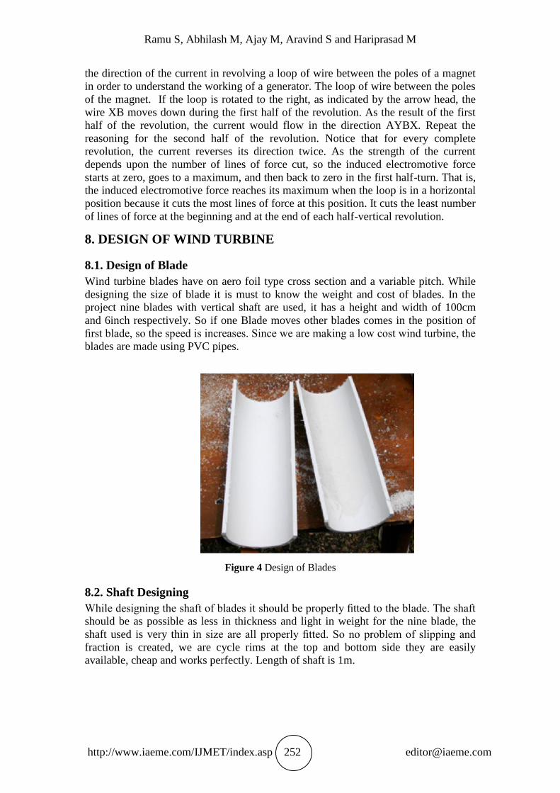
8.1. Design of Blade
Wind turbine blades have on aero foil type cross section and a variable pitch. While
designing the size of blade it is must to know the weight and cost of blades. In the
project nine blades with vertical shaft are used, it has a height and width of 100cm
and 6inch respectively. So if one Blade moves other blades comes in the position of
first blade, so the speed is increases. Since we are making a low cost wind turbine, the
blades are made using PVC pipes.
Figure 4 Design of Blades
8.2. Shaft Designing
While designing the shaft of blades it should be properly fitted to the blade. The shaft
should be as possible as less in thickness and light in weight for the nine blade, the
shaft used is very thin in size are all properly fitted. So no problem of slipping and
fraction is created, we are cycle rims at the top and bottom side they are easily
available, cheap and works perfectly. Length of shaft is 1m.
Low Expense Vertical Axis Wind Turbine Using Permanent Magnets
http://www.iaeme.com/IJMET/index.asp 253 [email protected]
Figure 5 Shaft Designing
8.3. Design of Bearing
For the smooth operation of Shaft, bearing mechanism is used. To have very less
friction loss the two ends of shaft are pivoted into the same dimension bearing. The
Bearing has diameter of 2.54cm. Bearing are generally provided for supporting the
shaft and smooth operation of shaft. We have used ball bearings for the purpose of
ease of maintenance.
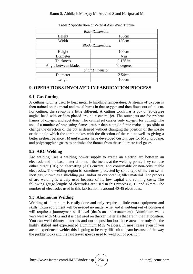
8.4. An Electric Dynamo
For generation of electricity from the designed our vertical axis wind turbine, we
chose generator that can be made by our surrounding materials. We select an old
ceiling fan, since it have the windings in it. We remove the rotating aluminium disk ie
the rotor and placed permanent magnets (neodymium) between the air gaps.14
magnets were placed according to the coils and closed the fan.
Figure 6 Ceiling Fan with Magnet Placed
Ramu S, Abhilash M, Ajay M, Aravind S and Hariprasad M
http://www.iaeme.com/IJMET/index.asp 254 [email protected]
Table 2 Specification of Vertical Axis Wind Turbine
Base Dimension
Height 100cm
Width 150cm
Blade Dimensions
Height 100cm
Diameter 6 in
Thickness 0.125 in
Angle between blades 40 degrees
Shaft Dimension
Diameter 2.54cm
Length 100cm
9. OPERATIONS INVOLVED IN FABRICATION PROCESS
9.1. Gas Cutting
A cutting torch is used to heat metal to kindling temperature. A stream of oxygen is
then trained on the metal and metal burns in that oxygen and then flows out of the cut.
For cutting, the set-up is a little different. A cutting torch has a 60- or 90-degree
angled head with orifices placed around a central jet. The outer jets are for preheat
flames of oxygen and acetylene. The central jet carries only oxygen for cutting. The
use of a number of preheating flames, rather than a single flame makes it possible to
change the direction of the cut as desired without changing the position of the nozzle
or the angle which the torch makes with the direction of the cut, as well as giving a
better preheat balance . Manufacturers have developed custom tips for Map, propane,
and polypropylene gases to optimize the flames from these alternate fuel gases.
9.2. ARC Welding
Arc welding uses a welding power supply to create an electric arc between an
electrode and the base material to melt the metals at the welding point. They can use
either direct (DC) or alternating (AC) current, and consumable or non-consumable
electrodes. The welding region is sometimes protected by some type of inert or semi-
inert gas, known as a shielding gas, and/or an evaporating filler material. The process
of arc welding is widely used because of its low capital and running costs. The
following gauge lengths of electrodes are used in this process 8, 10 and 12mm. The
number of electrodes used in this fabrication is around 40-45 electrodes.
9.3. Aluminium Welding
Welding of aluminium is easily done and only requires a little extra equipment and
skills. Extra equipment will be needed no matter what and if welding out of position it
will require a journeyman skill level (that’s an understatement). Aluminium welds
very well with MIG and it is best used on thicker materials that are in the flat position.
You can weld thinner materials and out of position but those areas are only for the
highly skilled and experienced aluminium MIG Welders. In most cases even if you
are an experienced welder this is going to be very difficult to learn because of the way
the puddle looks and the fast travel speeds used to weld out of position.
Low Expense Vertical Axis Wind Turbine Using Permanent Magnets
http://www.iaeme.com/IJMET/index.asp 255 [email protected]
10. OPERATIONS MODELING OF VAWT
The modelling of VAWT prototype is carried out in solid edge ST6, and this should
be helpful in predict the failure of wind turbine at various load. The different parts of
VAWT are shown in below.
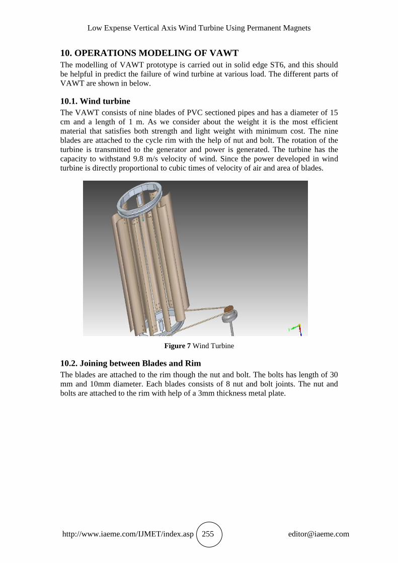
10.1. Wind turbine
The VAWT consists of nine blades of PVC sectioned pipes and has a diameter of 15
cm and a length of 1 m. As we consider about the weight it is the most efficient
material that satisfies both strength and light weight with minimum cost. The nine
blades are attached to the cycle rim with the help of nut and bolt. The rotation of the
turbine is transmitted to the generator and power is generated. The turbine has the
capacity to withstand 9.8 m/s velocity of wind. Since the power developed in wind
turbine is directly proportional to cubic times of velocity of air and area of blades.
Figure 7 Wind Turbine
10.2. Joining between Blades and Rim
The blades are attached to the rim though the nut and bolt. The bolts has length of 30
mm and 10mm diameter. Each blades consists of 8 nut and bolt joints. The nut and
bolts are attached to the rim with help of a 3mm thickness metal plate.
Ramu S, Abhilash M, Ajay M, Aravind S and Hariprasad M
http://www.iaeme.com/IJMET/index.asp 256 [email protected]
Figure 8 Joining Between Blades and Rim
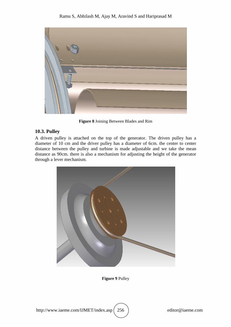
10.3. Pulley
A driven pulley is attached on the top of the generator. The driven pulley has a
diameter of 10 cm and the driver pulley has a diameter of 6cm. the center to center
distance between the pulley and turbine is made adjustable and we take the mean
distance as 90cm. there is also a mechanism for adjusting the height of the generator
through a lever mechanism.
Figure 9 Pulley
Low Expense Vertical Axis Wind Turbine Using Permanent Magnets
http://www.iaeme.com/IJMET/index.asp 257 [email protected]
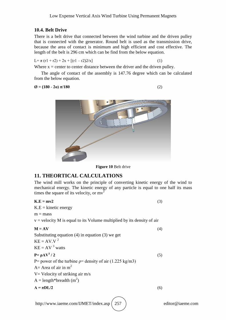
10.4. Belt Drive
There is a belt drive that connected between the wind turbine and the driven pulley
that is connected with the generator. Round belt is used as the transmission drive,
because the area of contact is minimum and high efficient and cost effective. The
length of the belt is 296 cm which can be find from the below equation.
L= π (r1 + r2) + 2x + [(r1 – r2)2/x] (1)
Where x = center to center distance between the driver and the driven pulley.
The angle of contact of the assembly is 147.76 degree which can be calculated
from the below equation.
Ø = (180 - 2α) π/180 (2)
Figure 10 Belt drive
11. THEORTICAL CALCULATIONS
The wind mill works on the principle of converting kinetic energy of the wind to
mechanical energy. The kinetic energy of any particle is equal to one half its mass
times the square of its velocity, or mv2
K.E = mv2 (3)
K.E = kinetic energy
m = mass
v = velocity M is equal to its Volume multiplied by its density of air
M = AV (4)
Substituting equation (4) in equation (3) we get
KE = AV.V 2
KE = AV 3 watts
P= ρAV3 / 2 (5)
P= power of the turbine ρ= density of air (1.225 kg/m3)
A= Area of air in m2
V= Velocity of striking air m/s
A = length*breadth (m2)
A = πDL/2 (6)
Ramu S, Abhilash M, Ajay M, Aravind S and Hariprasad M
http://www.iaeme.com/IJMET/index.asp 258 [email protected]
D = Diameter of the blade (m
L = Length of the blade (m)
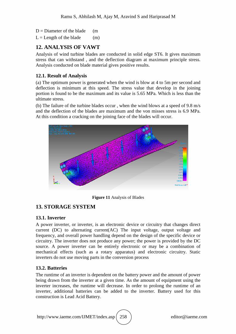
12. ANALYSIS OF VAWT
Analysis of wind turbine blades are conducted in solid edge ST6. It gives maximum
stress that can withstand , and the deflection diagram at maximum principle stress.
Analysis conducted on blade material gives positive results.
12.1. Result of Analysis
(a) The optimum power is generated when the wind is blow at 4 to 5m per second and
deflection is minimum at this speed. The stress value that develop in the joining
portion is found to be the maximum and its value is 5.65 MPa. Which is less than the
ultimate stress.
(b) The failure of the turbine blades occur , when the wind blows at a speed of 9.8 m/s
and the deflection of the blades are maximum and the von misses stress is 6.9 MPa.
At this condition a cracking on the joining face of the blades will occur.
Figure 11 Analysis of Blades
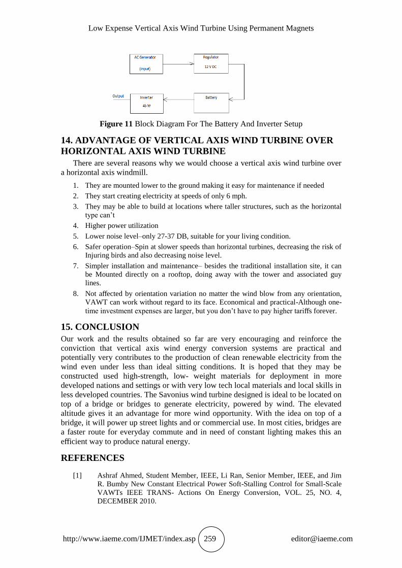
13. STORAGE SYSTEM
13.1. Inverter
A power inverter, or inverter, is an electronic device or circuitry that changes direct
current (DC) to alternating current(AC) The input voltage, output voltage and
frequency, and overall power handling depend on the design of the specific device or
circuitry. The inverter does not produce any power; the power is provided by the DC
source. A power inverter can be entirely electronic or may be a combination of
mechanical effects (such as a rotary apparatus) and electronic circuitry. Static
inverters do not use moving parts in the conversion process
13.2. Batteries
The runtime of an inverter is dependent on the battery power and the amount of power
being drawn from the inverter at a given time. As the amount of equipment using the
inverter increases, the runtime will decrease. In order to prolong the runtime of an
inverter, additional batteries can be added to the inverter. Battery used for this
construction is Lead Acid Battery.
Low Expense Vertical Axis Wind Turbine Using Permanent Magnets
http://www.iaeme.com/IJMET/index.asp 259 [email protected]
Figure 11 Block Diagram For The Battery And Inverter Setup
14. ADVANTAGE OF VERTICAL AXIS WIND TURBINE OVER
HORIZONTAL AXIS WIND TURBINE
There are several reasons why we would choose a vertical axis wind turbine over
a horizontal axis windmill.
1. They are mounted lower to the ground making it easy for maintenance if needed
2. They start creating electricity at speeds of only 6 mph.
3. They may be able to build at locations where taller structures, such as the horizontal
type can’t
4. Higher power utilization
5. Lower noise level–only 27-37 DB, suitable for your living condition.
6. Safer operation–Spin at slower speeds than horizontal turbines, decreasing the risk of
Injuring birds and also decreasing noise level.
7. Simpler installation and maintenance– besides the traditional installation site, it can
be Mounted directly on a rooftop, doing away with the tower and associated guy
lines.
8. Not affected by orientation variation no matter the wind blow from any orientation,
VAWT can work without regard to its face. Economical and practical-Although one-
time investment expenses are larger, but you don’t have to pay higher tariffs forever.
15. CONCLUSION
Our work and the results obtained so far are very encouraging and reinforce the
conviction that vertical axis wind energy conversion systems are practical and
potentially very contributes to the production of clean renewable electricity from the
wind even under less than ideal sitting conditions. It is hoped that they may be
constructed used high-strength, low- weight materials for deployment in more
developed nations and settings or with very low tech local materials and local skills in
less developed countries. The Savonius wind turbine designed is ideal to be located on
top of a bridge or bridges to generate electricity, powered by wind. The elevated
altitude gives it an advantage for more wind opportunity. With the idea on top of a
bridge, it will power up street lights and or commercial use. In most cities, bridges are
a faster route for everyday commute and in need of constant lighting makes this an
efficient way to produce natural energy.
REFERENCES
[1] Ashraf Ahmed, Student Member, IEEE, Li Ran, Senior Member, IEEE, and Jim
R. Bumby New Constant Electrical Power Soft-Stalling Control for Small-Scale
VAWTs IEEE TRANS- Actions On Energy Conversion, VOL. 25, NO. 4,
DECEMBER 2010.
Ramu S, Abhilash M, Ajay M, Aravind S and Hariprasad M
http://www.iaeme.com/IJMET/index.asp 260 [email protected]
[2] Guoying Feng Zhizhang Liu, Bao Daorina, Zheng Gong School of Energy and
Power Engi- neering Inner Mongolia University of Technology Hohhot, China.
Experimental Research on Vertical Axis Wind Turbine 2009 IEEE.
[3] Shengmao Li Engineering College Northeast Agricultural University Yan Li
Engineering Col- lege Northeast Agricultural University Harbin, China
Numerical study on the performance effect of solidity on the straight-bladed
vertical axis wind turbine. 2010 IEEE .
[4] Yi Guo, S. Hossein Hosseini, John N. Jiang, and Choon Yik Tang Voltage/Pitch
Control for Maximization and Regulation of Active/Reactive Powers in Wind
Turbines with Uncertain- ties t49th IEEE Conference on Decision and Control
December 15-17, 2010 Hilton Atlanta Hotel, Atlanta, GA, USA.
[5] Jianzhong Zhang, Ming Cheng, Zhe Chen, Xiaofan Fu Pitch Angle Control for
Variable Speed Wind Turbines DRPT2008 6-9 April 2008 Nanjing China .
[6] Faculty of Electrical Engineering, Automatic Control and Computer Science
Opole Univer- sity of Technology .Tomasz Boczar Faculty of Electrical
Engineering, Automatic Control and Computer Science Opole University of
Technology Analysis of low- frequency acoustic signals emitted by low-power
vertical axis wind turbine VAWT. 2013 IEEE .
[7] H. M. Hassan*, W. A. Farag, M. S. Saad, and Abdel Latif Elshafei Robust
Dynamic Output Feedback Pitch Control for Flexible Wind Turbines 2012 IEEE
[8] E. Muljadi C.P. Butterfield National Wind Technology Center National
Renewable Energy Laboratory (NREL). PITCH-CONTROLLED VARIABLE-
SPEED WIND TURBINE GENERATION Proceedings of Windpower 94, W,
May 10-13, 1994, Washington D.C.: American Wind Energy Association; pp.
513-522
[9] Lei SONG, Zong-Xiao YANG*, Rui-Tao DENG Institute of Systems Science
and Engineer- ing, Henan Engineering Laboratory of Wind Power Systems
Henan University of Science and Technology ,Xiao-Guang YANG Overall
Department Performance and Structure Optimization for a New Type of Vertical
Axis Wind Turbine Proceedings of the 2013 International Conference on
Advanced Mechatronic Systems, Luoyang, China, September 25-27, 2013.
[10] Wei Kou, Xinchun Shi, Bin Yuan, Lintao Fan Department of Electrical
Engineering North China Electric Power University Modeling Analysis and
Experimental Research on a Combined-Type Vertical Axis Wind Turbine 2011
IEEE .
[11] M.Z.I.Sajid, Dr. K. Hema Chandra Reddy and Dr.E.L. Nagesh, Design of
Vertical Axis Wind Turbine for Harnessing Optimum Power. International
Journal of Mechanical Engineering and Technology, 4(2), 2013, pp. 172–177
[12] Iessa Sabbe MOOSA, Powder Metallurgy and Its Application In The Production
of Permanent Magnets. International Journal of Mechanical Engineering and
Technology, 4(6), 2013, pp. 127–141
[13] Piyush Gulve and Dr. S.B.Barve, Design and Construction of Vertical Axis Wind
Turbine. International Journal of Mechanical Engineering and Technology,
5(10), 2014, pp. 148–155
[14] Placide JAOHINDY1, Franois GARDE1, Alain BASTIDE1. Aerodynamic and
MechanicalSystem Modeling of a vertical axis wind turbine (VAWT) 2011 IEEE.
[15] Tingna Shi1, Zhiyong Wu1, Ruying Gao2, Zhanfeng Song1, Changliang Xia1,3
1Department of Electrical Engineering and Automation, Tianjin University,
Study on Independent Blade Pitch Control for Huge Wind Turbines Wind
Energy, No.8, pp.481-485, 2005.