Embed Size (px)
Citation preview

Low latency and high throughput dynamic network infrastructures for high performance datacentre interconnects
Small or medium‐scale focused research project(STREP)
Co‐funded by the European Commission within the Seventh Framework Programme
Project no. 318606
Strategic objective: Future Networks (ICT‐2011.1.1)
Start date of project: November 1st, 2012 (36 months duration)
Deliverable D5.2
Control and data plane integration
Due date: 30/06/2015
Submission date: 13/07/2015
Deliverable leader: UPC
Author list: Fernando Agraz, Salvatore Spadaro, Albert Pagès (UPC), Bingli Guo, Yi Shu, Yan Yan,
Shuping Peng, Dimitra Simeonidou (UNIVBRIS), Wang Miao, Nicola Calabretta
(TUE), Giacomo Bernini, Nicola Ciulli (NXW), Alessandro Predieri, Matteo Biancani
(IRT), Jose Carlos Sancho (BSC)
Dissemination Level
PU: Public
PP: Restricted to other programme participants (including the Commission Services)
RE: Restricted to a group specified by the consortium (including the Commission Services)
CO: Confidential, only for members of the consortium (including the Commission Services)
Ref. Ares(2015)2960805 - 14/07/2015

2
Abstract
The aim of this deliverable is to report the integration between the LIGHTNESS hybrid optical data plane
developed in WP3 and based on both Optical Circuit Switching (OCS) and Optical Packet Switching (OPS)
technologies with the SDN controller for data centre networks released by WP4. This integration has been
achieved through the proper design and development of the OpenFlow‐based southbound interfaces. The
deliverable also reports the experimental validation of the provisioning of virtual slices with QoS guarantees,
involving the mapping of the virtual links on both OCS and OPS resources. The experimental validation has
been successfully conducted, as a first step towards the final demonstration of the overall LIGHTNESS
concepts, including applications running within the developed data centre network encompassing hybrid
optical technologies operated by means of an SDN controller.

3
Table of Contents
Table of Contents 3
0. Executive Summary 5
1. Introduction 6
2. Integration and experimental validation of LIGTHNESS data and control planes 8
2.1. SDN‐controlled Optical NIC 8
2.2. SDN‐controlled Architecture‐on‐Demand Node 10
2.3. SDN‐controlled OPS switch 13
3. Experimental assessment of the overall intra‐cluster architecture 17
3.1. OPS/OCS connectivity provisioning 17
3.2. Virtual Data Centre Composition 19
3.2.1. VDC composition in the experimental setup 19
3.2.2. VDC configurations 19
3.2.3. VDC deployment time 20
3.3. SDN‐enabled OPS virtual network provisioning with QoS guarantees 20
3.3.1. VN Reconfiguration 22
3.3.2. Priority Assignment 23
3.3.3. Statistics Report and Load Balancing 25
3.4. SDN‐controlled OPS for multicast‐enabled virtual networks 26
4. Conclusions 29
5. References 30
6. Acronyms 31

4
Figure Summary
Figure 1‐1: SDN enabled Hybrid OPS/OCS DCN LIGHTNESS testbed ......................................................................6 Figure 2‐1: FPGA‐based optical NIC LUT address map ...........................................................................................9 Figure 2‐2: OF FEATURES_REPLY message for FPGA‐based optical NIC .............................................................. 10 Figure 2‐3: OF configuration message for FPGA‐based optical NIC .................................................................... 10 Figure 2‐4: Intra‐data centre network architecture with optical ToR ................................................................ 11 Figure 2‐5: Optical ToR implemented with NxM WSS ......................................................................................... 12 Figure 2‐6: OF configuration message (OF CFLOW_MOD) between ODL controller and optical ToR OF agent . 12 Figure 2‐7: OF configuration message (OF CFLOW_MOD) between ODL controller and AoD OF agent ............ 12 Figure 2‐8: OF FEATURES_REPLY message between ODL controller and AoD OF agent .................................... 13 Figure 2‐9: OF FEATURES_REPLY message between ODL controller and optical ToR OF agent ......................... 13 Figure 2‐10: (a) SDN controlled OPS (b) OF agent implementation scheme ....................................................... 14 Figure 2‐11: OpenFlow OF FEATURES_REPLY extended message ....................................................................... 15 Figure 2‐12: (a) OpenDaylight GUI with OPS extensions; (b) OpenFlow OF FLOW_MOD extended message ... 16 Figure 3‐1: Optical NIC and Optical ToR Integration Experiment setup ............................................................. 17 Figure 3‐2: Control message workflow of OPS and OCS Provisioning ................................................................. 18 Figure 3‐3: Optical spectrum through Optical WSS different configuration ....................................................... 18 Figure 3‐4: Virtual optical DCs deployment and configurations ......................................................................... 20 Figure 3‐5: Virtual Network creation and reconfiguration .................................................................................. 21 Figure 3‐6 SDN‐enabled OPS node ...................................................................................................................... 22 Figure 3‐7: Virtual networks reconfiguration ...................................................................................................... 23 Figure 3‐8: Time traces for labels and packets before/after LUT update (VN reconfiguration) ......................... 23 Figure 3‐9: (a) Priority assignment; (b) time traces of Flow 4 and Flow 5; (c) packet loss and latency. ............. 24 Figure 3‐10: OF STATS_REPLY messages for (a) OPS and (b) ToR ........................................................................ 25 Figure 3‐11: (a) Load balancing operation; packet loss and latency changes without adjusting (b) and with
balancing step of 0.15 (c) ............................................................................................................................ 26 Figure 3‐12 OPS‐based multicast scenario .......................................................................................................... 27 Figure 3‐13 OF FLOW_MOD message for OPS multicast flow ............................................................................. 28 Figure 3‐14 OPS multicast flow detail in the ODL GUI ......................................................................................... 28

5
0. Executive Summary
The integration between the different systems and components for data and control plane that have been
implemented and released as prototypes in WP3 and WP4 respectively is the first step towards the final
demonstration of the LIGHTNESS solutions for future data centre networks. While the developed OCS and OPS
systems have been validated separately in WP3, and the SDN controller in WP4, this deliverable reports the
integration of all these systems in the LIGHTNESS testbed, including thus both data and control planes. Such
integration is achieved on one hand through the proper optical interfaces among the different data plane
components (Optical Network Interface Card (NIC), OCS‐based on Architecture on Demand (AoD) node, OPS
and Top of the Rack (ToR)); on the other, it is achieved through the OpenFlow‐based southbound interface
that enable the remote control and management of data plane optical devices from the OpenDayLight (ODL)
SDN controller, to make fully dynamic and programmable the LIGHTNESS data centre network. This
deliverable reports the experimental validation of the developed OpenFlow (OF) protocol and interfaces to
enable the communication between the control and data plane systems; moreover, it also presents some
experimental assessment of the dynamic provisioning of unicast and multicast‐based virtual slices over the
heterogeneous optical LIGHTNESS data plane. Some figures of merit, such as the virtual slices provisioning
time, are also reported.
This successful validation of integrated components is therefore the first action achieved for the final
demonstrations of the overall intra and inter‐cluster LIGHTNESS architecture, that will be performed in
upcoming activities in WP5 to show the benefits of the designed solutions, not only in terms of QoS
guarantees for the running applications but also in terms of optimised usage of the available DCN resources.
6
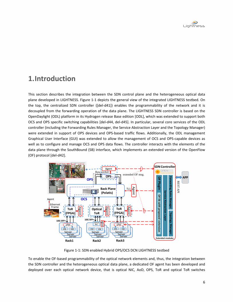
1. Introduction
This section describes the integration between the SDN control plane and the heterogeneous optical data
plane developed in LIGHTNESS. Figure 1‐1 depicts the general view of the integrated LIGHTNESS testbed. On
the top, the centralized SDN controller ([del‐d41]) enables the programmability of the network and it is
decoupled from the forwarding operation of the data plane. The LIGHTNESS SDN controller is based on the
OpenDaylight (ODL) platform in its Hydrogen release Base edition [ODL], which was extended to support both
OCS and OPS specific switching capabilities [del‐d44, del‐d45]. In particular, several core services of the ODL
controller (including the Forwarding Rules Manager, the Service Abstraction Layer and the Topology Manager)
were extended in support of OPS devices and OPS‐based traffic flows. Additionally, the ODL management
Graphical User Interface (GUI) was extended to allow the management of OCS and OPS‐capable devices as
well as to configure and manage OCS and OPS data flows. The controller interacts with the elements of the
data plane through the SouthBound (SB) interface, which implements an extended version of the OpenFlow
(OF) protocol [del‐d42].
Figure 1‐1: SDN enabled Hybrid OPS/OCS DCN LIGHTNESS testbed
To enable the OF‐based programmability of the optical network elements and, thus, the integration between
the SDN controller and the heterogeneous optical data plane, a dedicated OF agent has been developed and
deployed over each optical network device, that is optical NIC, AoD, OPS, ToR and optical ToR switches
OpticalToR
Agen
t
ServerVM VM
OVS
ServerVM VM
OVS
Agen
t
Agent
ToR(FPGA)
Agen
t
ServerVM VM
Rack1
OVS
Ethernet Frame
Agent
10G SFP+
ToR(FPGA)
Agen
t
ServerVM VM
OVS
ServerVM VM
OVS
ServerVM VM
Rack2
ServerVM VM
OVS
ServerVM VM
OVS
ServerVM VM
Rack3
OVS
TL1
Raw socketextended OF msg.
OPS
Back Plane (Polatis)
OPS Forw
arding R
ules M
anage
rTopology
Manage
r
Service
Abstractio
n Laye
r
OF P
lugin
OFlib
with
proposed exte
nsio
n
Extended modules
SDN Controller
APP
RE
ST
AP
I
Optical NIC
Agent
10G SFP+
OCS

7
respectively. These OF agents act as a mediation entity between the SDN controller OF‐based SB interface and
the proprietary control interface exposed by each device [del‐d44, del‐d45]. Hence, the main role of the OF
agent is to translate the OF messages coming from the SB interface to the appropriate set of commands to
configure the look‐up tables (LUTs) of the optical devices as it has been deeply detailed in [del‐d32].
The next chapters presents the results of the experimental activities carried out within the testbed depicted in
Figure 1‐1 to validate the integration of the LIGHTNESS SDN controller with the different optical devices on
one hand, and to assess the intra‐cluster data centre network architecture for connectivity provisioning and
virtual slices and Virtual Data Centre (VDC) composition.
8
2. Integration and experimental validation of LIGTHNESS data and control planes
The purpose of this section is to detail the integration and functional validation of the ODL‐based
SDN controller with the different systems of the optical data plane designed and implemented in
LIGHTNESS and that will be showcased all together in the final demonstration. Therefore, the
integration of the SDN controller with the optical NIC, the OCS‐capable Architecture‐on‐Demand
(optical ToR) and the OPS switches is detailed. The integration of the electrical ToR and the SDN
controller has been already reported in [del‐d47].
2.1. SDN‐controlled Optical NIC
The FPGA‐based optical NIC communicates with the OF agent through 10Gbps Ethernet interface.
The fibre connects the SFP+ module on the FPGA‐based optical NIC and the agent. The commands
and information are capsulated in a pre‐defined 1504 Byte Ethernet Frame (VLAN). This
communication is bidirectional. On one way, when the FPGA‐based optical NIC receives the pre‐
defined Ethernet frame from the agent, the decoder in the optical NIC is capable of translating the
information from the Ethernet frame to the FPGA‐based Look‐up‐table (LUT) set of entries. Thus, the
other FPGA‐based functional blocks can follow the commands of the SDN controller by reading and
checking the LUT. On the other way, when the SDN controller needs to get the information and
status from the optical NIC, it can send, through the dedicated OF agent, a pre‐defined Ethernet
frame with the “pull all” command, so that the FPGA‐based optical NIC sends out the Ethernet frame
with its LUT information.
The structure and mapping of the FPGA‐based LUT and the pre‐defined Ethernet frame are shown in
Figure 2‐1. The Ethernet frame with the VLAN is fixed at 1504 bytes. Therefore, the optical NIC will
discard any other size of received Ethernet frames. We predefined the node ID as the first byte of
destination MAC address in the Ethernet frame in order to distinguish the different FPGA‐based
optical NIC in the network. The mechanism supports “push”, “pull” and “modify” functions; “push”
means update all the commands in the LUT with the information capsulated in the received Ethernet
Frame; “pull” means sending all the stored information in the LUT to the agent; and “modify” means
updating the LUT with the information in the Ethernet frame that is not “0”. This is only valid for OPS
switch control commands. These functions are set in the last byte of the destination MAC address.
By setting different numbers, the commands in the LUT can be updated on demand.

9
Figure 2‐1: FPGA‐based optical NIC LUT address map
In Figure 2‐1, the blue column shows the mapping in the Ethernet frame (captured by Wireshark),
and the purple column shows the mapping in FPGA‐based LUT RAM. There are also several other
parameters, that is, Keep alive message length, optical packet length, Ethernet/OPS mode, OPS
switch information, and Header matching. In particular:
Keep alive message length parameter is compulsory for recovering the receiver clock, the
programmability allows the FPGA‐based optical NIC adapt to variable optical QoS/QoT.
Optical packet length is the parameter for OPS packet length.
Ethernet/OPS mode can be set on‐demand, that FPGA‐based optical NIC is capable of hitless
switchover between Ethernet and OPS on‐the‐fly.
OPS switch information stores the labels for OPS switch.
Header matching includes the header (i.e., Destination MAC address, Source MAC address
and VLAN ID) and matching mask. The matching mask is by bit which allows to matching the
header information by bit on‐demand.
It is worth noting that the throughput and latency performance can be impacted by the keep alive
message length and optical packet length. By fixing the minimum keep alive message length, and
adjusting the optical packet length, the throughput and latency performance can result
compromised. More details of the function of optical NIC have already been reported in [del‐d33].
To enable the programmability of the optical NIC, the OF agent mediates the communication
between the SDN controller and the optical NIC hardware. The detailed function decomposition and
message exchanging flow between the SDN controller, the OF agent and the NIC hardware are
described and detailed in [del‐d45]. Also, the OF protocol has been properly extended to configure
the optical NIC, as defined in [del‐d42]. In particular, two new actions for OF FLOW_MOD message
have been introduced in support of optical NIC operation: set_ops_label to set the proper optical
label (as instructed by the SDN controller) for OPS usage, and set_time_slot_size to program the OPS
optical packet length to be generated by the NIC (in its time slotted based operation).
Ethernet Frame
lines (Captured
by Wireshark)LUT RAM
ADDR\BYTE 31 30 29 28 27 26 25 24 23 22 21 20 19 18 17 16 15 14 13 12 11 10 9 8 7 6 5 4 3 2 1 0
0 01,02
00 10,20 03,04,05,06
01 30,40 07,08,09,10
02 50,60 11,12,13,14
03 70,80 15,16,17,18
04 90,a0 19,20,21,22
05 b0,c0 23,24,25,26
06 d0,e0 27,28,29,30
07 f0,100 31,32,33,34
08 110,120 35,36,37,38
09 130,140 39,40,41,42
10 150,160 43,44,45,46
11 170,180 47,48,49,50
12 190,1a0 51,52,53,54
13 1b0,1c0 55,56,57,58
14 1d0,1e0 59,60,61,62
15 1f0,200 63,64,65,66
16 210,220 67,68,69,70
17 230,240 71,72,73,74
18 250260 75,76,77,78
19 270,280 79,80,81,82
20 290,2a0 83,84,85,86
21 2b0,2c0 87,88,89,90
22 2d0,2e0 91,92,93,94
23 2f0,300 95,96,97,98
OPS switch information channel1
OPS switch information channel1
OPS switch information channel2
OPS switch information channel2
OPS switch information channel2
Header (Buffer 1)
OPS switch information channel1
OPS switch information channel2
OPS switch information channel2
OPS switch information channel2
Header (Buffer 4)
FPGA‐based Optical NIC LUT Address MAP
OPS switch information channel1
OPS switch information channel1
OPS switch information channel1
Destination MAC AddressSource MAC Address
RESERVED
Keep alive message length (10) Optical packet length (09) Ethernet/OPS MODE
Header (Buffer 4)
Header (Buffer 2)
Header (Buffer 3)
Header (Buffer 1)
Header (Buffer 2)
Header (Buffer 3)

10
Figure 2‐2 shows the switch feature report (OF FEATURES_REPLY) message sent from optical NIC
agent to SDN controller. In details, it will provide the total circuit port number the NIC card have, the
supported actions, as well as the capability (e.g., statistics and switching capability).
Figure 2‐2: OF FEATURES_REPLY message for FPGA‐based optical NIC
Figure 2‐3 shows the configuration message (OF FLOW_MOD) sent from SDN controller to the NIC
OF agent. Specifically, vlan_id is configured to match the incoming traffic and, as mentioned in the
previous section, source or destination MAC could also be used in the matching filed. For the
matched traffic, it will be forwarded to the out_put port set by the OUT_PORT action. If the
configuration is for an OPS connection, another action will be added to indicate the optical label
which will be attached to the optical packet.
Figure 2‐3: OF configuration message for FPGA‐based optical NIC
2.2. SDN‐controlled Architecture‐on‐Demand Node
An overall picture of the DCN architecture including the optical Top of the Rack (ToR) switch is
illustrated in Figure 2‐4. The optical NIC, which is part of the server, can aggregate the traffic from
the server, sort out between the long and the short‐lived traffic and map it to different transponders.
Thus, the hybrid OPS/OCS switchover functions can be implemented directly in the NIC on the server.
In light of this, the ToR switch on each rack does not need to employ any electronic platform but
contains only pure optical components with fixed interfaces connected to each server in the rack,
acting as a passive optical switch. Traffic between different racks is directed to optical switching
nodes, i.e. OCS or OPS, through the optical ToR switch and the AoD without any extra latency
(besides the latency introduced by the propagation over the optical link). The optical NIC also
includes a group of multi‐channels based on Vertical‐Cavity Surface‐Emitting Laser (VCSEL)
technology (e.g., Avago MiniPods) for intra‐rack communication. This way, optical connectivity
among all the servers in a rack is achieved. With this approach, both the communication between

11
servers within the same rack and the traffic exchange between servers in different racks do not need
to go through any electronic ToR switch via optical‐electro‐optical conversion, preventing thus
additional latency. In consequence, this approach introduces high efficiency with direct server‐to‐
server links. Considering the data plane architecture in Figure 2‐4, OPS/OCS channels from the
optical ToRs are connected to the AoD node. This is an optical programmable system deploying the
Architecture‐on‐Demand (AoD) concept, which can be controlled by the SDN‐based control plane.
The AoD configuration utilizes Polatis beam‐steering switch [Polatis] as the optical backplane, which
are connected to various optical function modules and all the optical ToRs. With this architecture,
different arrangements of inputs/outputs and modules can be constructed by setting up appropriate
cross‐connections in the optical backplane. Thus, synthetic node architectures can be dynamically
created involving only the required transmission and functionality. Utilizing such programmability,
the AoD node is capable to deliver various network topologies and functions on demand. For
example, if OPS switching capability is required, the corresponding link can be connected to an OPS
module directly (red line in the figure). Likewise, OCS links can be established by connecting OCS‐
enabled channels directly between two ToRs through the AoD node (blue line). All ToRs and NICs are
connected with the SDN‐based controller, and so does the AoD node. Thus, the control layer can
configure and enable OPS/OCS function for each intra‐cluster connection.
Figure 2‐4: Intra‐data centre network architecture with optical ToR
The utilization of WSS switches in the optical ToR provides high flexibility. As illustrated in Figure 2‐5,
an NxM WSS switch with M input ports and N output ports can switch programmable C‐band
spectrum slots from 10‐GHz up to 5‐THz with a 1‐GHz resolution between arbitrary ingress and
egress ports of the WSS. Thus, apart from tuning the input wavelength for each channel, channels
from each NIC can be selected at will and aggregated at an arbitrary output port. The reassembled
traffic is then switched to OPS or OCS accordingly and sent to the specific port of WSS on receiving
side so that the required server can receive it. The definitions of WSS ports number N and M depend
highly on which type of NxM WSS is commercially available, e.g. 4*16 Finisar Waveshaper. The WSS
switches can be controlled by the SDN‐based control plane.

12
Figure 2‐5: Optical ToR implemented with NxM WSS
To enable the SDN‐based control of the AoD node and the optical ToR, two dedicated OF agents
have been developed; the detailed functional modules have been fully reported in [del‐d4.4, del‐
d45]. More specifically, to configure the WSS‐based optical ToR, WDM based cross‐connection is
leveraged (indicated by wildcards bits), and wave_port defined in OF 1.0 with optical circuit
extensions [OF] is used to send out the input/output port, bandwidth and central frequency
information as shown in Figure 2‐6. Also, Figure 2‐7 shows the OF configuration message (OF
CFLOW_MOD) sent from the SDN controller to the OF agent of the AoD, which indicates a port based
cross‐connection.
Figure 2‐6: OF configuration message (OF CFLOW_MOD) between ODL controller and optical ToR OF
agent
Figure 2‐7: OF configuration message (OF CFLOW_MOD) between ODL controller and AoD OF agent
Figure 2‐8 and Figure 2‐9 show the switch feature message reported from AoD and optical ToR agent
to the SDN controller, including the supported capability and circuit port number, as well as each
port features.

13
Figure 2‐8: OF FEATURES_REPLY message between ODL controller and AoD OF agent
Figure 2‐9: OF FEATURES_REPLY message between ODL controller and optical ToR OF agent
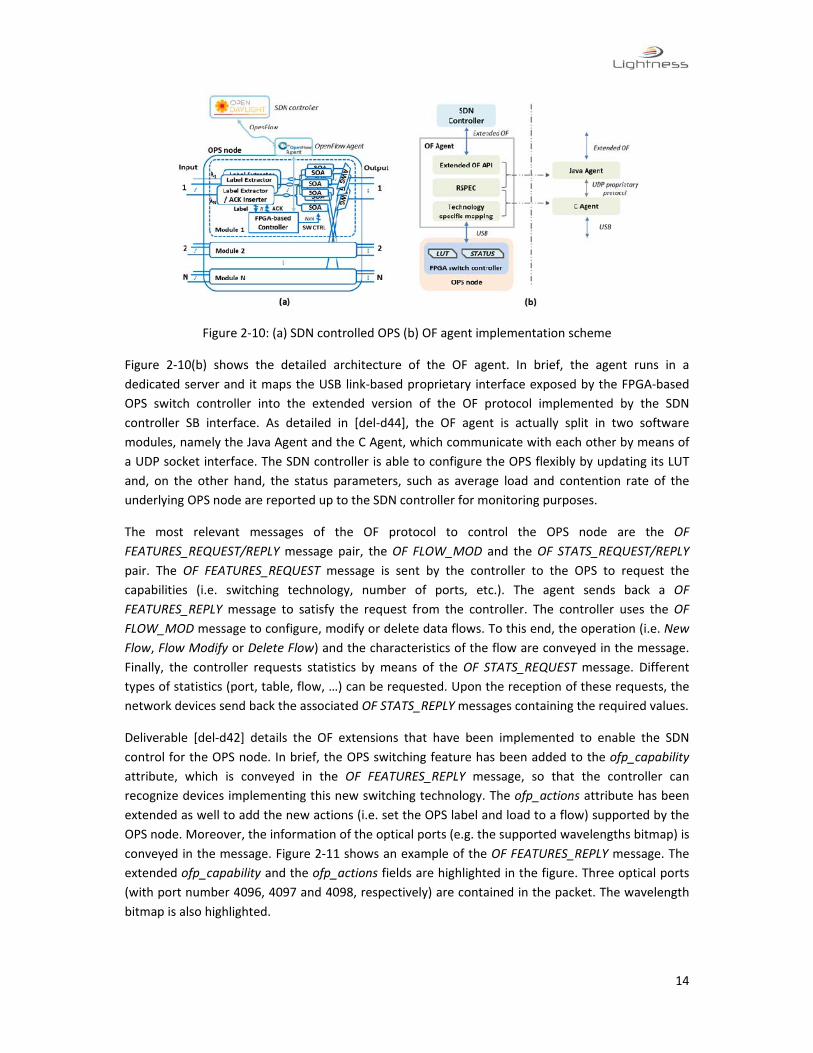
2.3. SDN‐controlled OPS switch
Figure 2‐10 (a) depicts the general view of the integration between the SDN‐based control plane and
the OPS switch. Residing on top of the OPS, the centralized SDN controller ([del‐d41]) enables the
programmability of the network and it is decoupled from the forwarding operation of the switch.
The OpenDaylight platform has been extended to support the OPS specific features and switching
capabilities. The controller interacts with the OPS node through the SB interface, which implements
an extended version of the OF protocol (as detailed in [del‐d42]). To enable the OF‐based
programmability, a dedicated OF agent is deployed over the OPS switch. The main role of the OF
agent is to translate the OF messages coming from the SB interface to the appropriate set of
commands to configure the look‐up table (LUT) of the OPS switch, as it has been detailed in [del‐
d32]. Moreover, [del‐d44] and [del‐d45] provide extensive description of the OF agents that have
been designed and implemented.
14
Figure 2‐10: (a) SDN controlled OPS (b) OF agent implementation scheme
Figure 2‐10(b) shows the detailed architecture of the OF agent. In brief, the agent runs in a
dedicated server and it maps the USB link‐based proprietary interface exposed by the FPGA‐based
OPS switch controller into the extended version of the OF protocol implemented by the SDN
controller SB interface. As detailed in [del‐d44], the OF agent is actually split in two software
modules, namely the Java Agent and the C Agent, which communicate with each other by means of
a UDP socket interface. The SDN controller is able to configure the OPS flexibly by updating its LUT
and, on the other hand, the status parameters, such as average load and contention rate of the
underlying OPS node are reported up to the SDN controller for monitoring purposes.
The most relevant messages of the OF protocol to control the OPS node are the OF
FEATURES_REQUEST/REPLY message pair, the OF FLOW_MOD and the OF STATS_REQUEST/REPLY
pair. The OF FEATURES_REQUEST message is sent by the controller to the OPS to request the
capabilities (i.e. switching technology, number of ports, etc.). The agent sends back a OF
FEATURES_REPLY message to satisfy the request from the controller. The controller uses the OF
FLOW_MOD message to configure, modify or delete data flows. To this end, the operation (i.e. New
Flow, Flow Modify or Delete Flow) and the characteristics of the flow are conveyed in the message.
Finally, the controller requests statistics by means of the OF STATS_REQUEST message. Different
types of statistics (port, table, flow, …) can be requested. Upon the reception of these requests, the
network devices send back the associated OF STATS_REPLY messages containing the required values.
Deliverable [del‐d42] details the OF extensions that have been implemented to enable the SDN
control for the OPS node. In brief, the OPS switching feature has been added to the ofp_capability
attribute, which is conveyed in the OF FEATURES_REPLY message, so that the controller can
recognize devices implementing this new switching technology. The ofp_actions attribute has been
extended as well to add the new actions (i.e. set the OPS label and load to a flow) supported by the
OPS node. Moreover, the information of the optical ports (e.g. the supported wavelengths bitmap) is
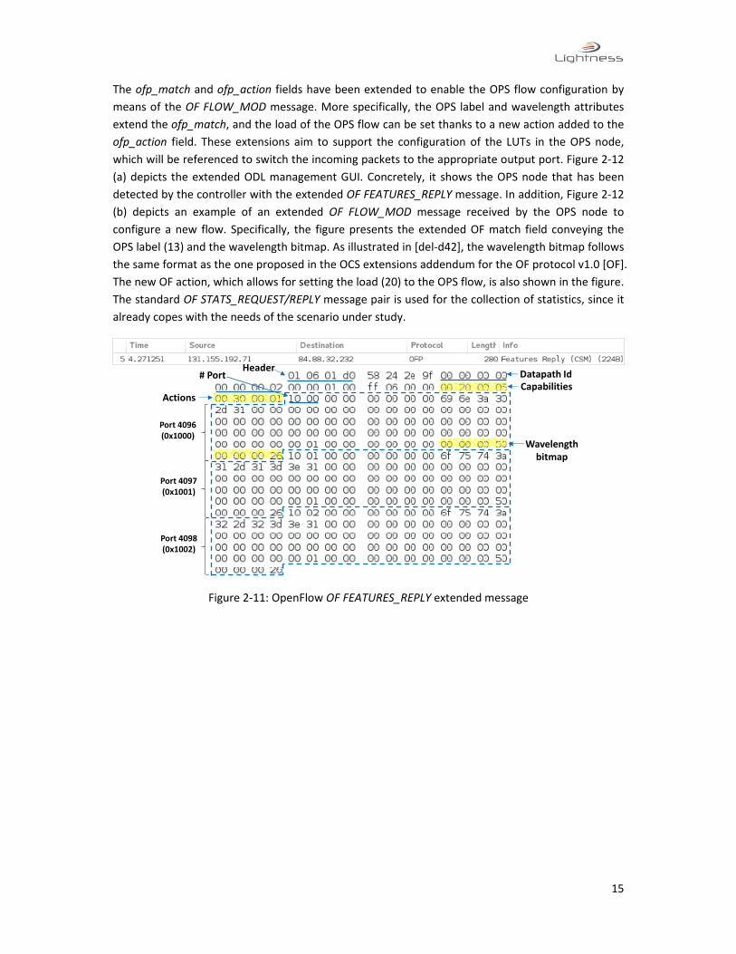
conveyed in the message. Figure 2‐11 shows an example of the OF FEATURES_REPLY message. The
extended ofp_capability and the ofp_actions fields are highlighted in the figure. Three optical ports
(with port number 4096, 4097 and 4098, respectively) are contained in the packet. The wavelength
bitmap is also highlighted.
15
The ofp_match and ofp_action fields have been extended to enable the OPS flow configuration by
means of the OF FLOW_MOD message. More specifically, the OPS label and wavelength attributes
extend the ofp_match, and the load of the OPS flow can be set thanks to a new action added to the
ofp_action field. These extensions aim to support the configuration of the LUTs in the OPS node,
which will be referenced to switch the incoming packets to the appropriate output port. Figure 2‐12
(a) depicts the extended ODL management GUI. Concretely, it shows the OPS node that has been
detected by the controller with the extended OF FEATURES_REPLY message. In addition, Figure 2‐12
(b) depicts an example of an extended OF FLOW_MOD message received by the OPS node to
configure a new flow. Specifically, the figure presents the extended OF match field conveying the
OPS label (13) and the wavelength bitmap. As illustrated in [del‐d42], the wavelength bitmap follows
the same format as the one proposed in the OCS extensions addendum for the OF protocol v1.0 [OF].
The new OF action, which allows for setting the load (20) to the OPS flow, is also shown in the figure.
The standard OF STATS_REQUEST/REPLY message pair is used for the collection of statistics, since it
already copes with the needs of the scenario under study.
Figure 2‐11: OpenFlow OF FEATURES_REPLY extended message
HeaderDatapath Id
Actions
# Port
Wavelengthbitmap
Port 4096 (0x1000)
Port 4097 (0x1001)
Port 4098 (0x1002)
Capabilities

16
Figure 2‐12: (a) OpenDaylight GUI with OPS extensions; (b) OpenFlow OF FLOW_MOD extended
message

17
3. Experimental assessment of the overall intra‐cluster architecture
3.1. OPS/OCS connectivity provisioning
In the experimental setup shown in Figure 3‐1, an AoD node is composed by a 192×192 Polatis fiber
switch attached with a 2×2 OPS switch and other elements such as (De)Mux plugged. Optical ToR
switches are implemented based on 4*16 Waveshaper and all the ToR switches are connected to the
backplane via optical links. Servers are connected to Optical ToRs via 10GE CWDM SFP+ links.
Different from the results presented in [del‐d51], here it is reported the OPS and OCS connection
provisioning involving the optical NIC built in the server. Moreover, dynamic OPS/OCS data flows
configuration is also experimentally assessed.
Figure 3‐1: Optical NIC and Optical ToR Integration Experiment setup
Figure 3‐2(a) shows the workflow for OPS and OCS connection provisioning approach. Generally,
applications (e.g., Virtual Data Centre allocation) need to work out the required connections (as well
as the paths) to enable the communication between different VMs running in physical servers, and
push flows to configure the traversed optical switches or the forwarding rules in the optical NIC. All
these configurations are received by ODL via Representational state transfer (REST) API, which have
also been extended to enable optical flow installation. In this experiment, packets generated in the
server are forwarded to different output ports and have different sending mode (i.e., OPS or OCS)
according to the flow entries installed in NIC, which are provisioned and updated by ODL. As shown
in Figure 3‐2 (b), to establish an OCS connection, the cross‐connection in the AoD backplane (OF
CFLOW_MOD, as shown in Figure 2‐7), flow entries in source and destination ToRs (OF CFLOW_MOD,
as shown in Figure 2‐6), as well as flow entries (OF FLOW_MOD, as shown in Figure 2‐3) in source
and destination NICs need to be configured. As shown in Figure 3‐2 (a), for the OPS connection,
besides a flow entry with label configuration information sent to the source optical NIC, another
flow for the OPS node need to be installed to update the OPS LUT. The measured time required
updating the LUTs of the OPS and the backplane are the same as what we measured in

18
demonstration presented in [del‐d51]. The measured WSS cross‐connection configuring time is
around 300ms. The figure shows the new set_ops_label action added to the OF FLOW_MOD, which
is processed by the ToR. Also, we have extended the action set of the OF FLOW_MOD message with
a new action to set the OPS optical frame length (in time dimension) in the optical NIC.
Back Plane OPS
ODL GUI/REST
Optical ToR
cflow_modcflow_mod
flow_mod
(a) OPS connectionprovisioning
Optical NIC
Back Plane
ODL GUI/REST
Optical ToR
cflow_mod
flow_mod
cflow_mod
(b)OCS connectionprovisioning
Optical NIC
flow_mod
Figure 3‐2: Control message workflow of OPS and OCS Provisioning
Figure 3‐3 shows the optical spectrum of three SFP+ channels (from single optical NIC card) going
through the Waveshaper but with different configuration. Figure 3‐3 (a) shows that all the three
channels go to the same output port, while Figure 3‐3 (b) and (c) shows three channels going to
different output ports. It has been measured that the signal suffers around 5dBm insertion loss
when going through the WSS‐based optical ToR.
(a) (b)
(c)
Figure 3‐3: Optical spectrum through Optical WSS different configuration

19
3.2. Virtual Data Centre Composition
Data centre operators and providers need virtualization mechanisms and technologies to efficiently
multiplex customers within their physical network and IT infrastructures. Since multi‐tenancy has
arisen as a key requirement for future data centres, the following scenarios have been
experimentally setup to demonstrate how the LIGHTNESS solution can cope with it.
An experimental setup to demonstrate the dynamic Virtual Data Centre (VDC) composition in the
optical data centre has been implemented; the aim has been to evaluate its performance by
measuring the time to successfully deploy VDC upon a tenant request. The configurations
provisioned by the SDN controller to each data centre network device using the extended OF
protocol (AoD backplane, OPS, and ToR/NIC) are also shown in this section.
3.2.1. VDC composition in the experimental setup
In this experiment, a Polatis switch with 192×192 ports is used as the backplane of the AoD node. An
OPS switch and ToR/NIC are plugged into the backplane. Servers are connected to ToR/NIC via 10GE
SFP+. The ToR/NIC are implemented with FPGA optoelectronics with 12×10GE ports, which can be
configured by the SDN controller via the corresponding OF agent. The OPS switch is implemented
with SOA based fast switch and RF tones labelling technique, as well as an FPGA‐based local
controller [Miao14].
Three VDC requests are created containing certain capacity requirements on their virtual nodes and
virtual links, following the approach described in [del‐d47, del‐d45]. Bidirectional communications
are considered while deploying the VDC requests, that is, one virtual link is allocated with two
bidirectional physical lightpaths. Before the VDC deployment, the VDC requester is not concerned
and is unaware of the physical location of nodes and links allocated to the VDC. The VDC requester
will call the VDC composition application to process the request following the procedure described
in [Peng15]. Labels (1/2) are used to indicate the switching of optical packets transmitted over the
same input port/wavelength to different output ports.
3.2.2. VDC configurations
After processing a VDC request, the SDN controller pushes the devices' configurations via the
extended OF protocol. These are then translated into technology specific control messages by the OF
agents of these devices. As an example, three virtual slices are created and the network
configuration items are shown in Figure 3‐4a. One selected configuration item for each device is
expanded and the extended OpenFlow messages are also shown in Figure 3‐4a. The REST call is
shown in Figure 3‐4b. Regarding the Backplane, OF CFLOW_MOD indicates the input and output
ports of the requested optical cross connection, which is extended from the OpenFlow 1.0 with

20
addendum draft v0.3 [OF]. Regarding the OPS switch, OF FLOW_MOD is extended by adding optical
label (4 bytes) and wavelength (8 bytes) information in the matching fields. The corresponding input
and output ports are also indicated. Regarding the ToR switch, OF FLOW_MOD indicates the VLAN
ID for packet matching and extended with OPS label setting action if the matched packet is going to
be delivered via an OPS connection.
In order to allocate resources (i.e. vCPU and Memory) for VMs, the flavour list and OS (Operating
System) type in the image list need to be predefined.
Figure 3‐4: Virtual optical DCs deployment and configurations
3.2.3. VDC deployment time
The breakdown of the total time for successfully deploying a VDC request is given in [del‐d47], which
comprises of: 1) VDC application execution (to call the VDC deployment algorithm engine) (35.12ms);
2) information processing and message exchanges in the OpenDaylight SDN controller (195ms) and
OpenStack cloud management system (158ms); and 3) device configurations (25ms). The total
deployment time is 255.12ms.
3.3. SDN‐enabled OPS virtual network provisioning with QoS
guarantees
The scenario here considered takes advantage of the OPS technology switching capabilities (in terms
of high flexibility and utilization) to provide isolated virtual network (VN) infrastructures to the
customers. More specifically the ODL LIGHTNESS SDN controller is used to effectively and efficiently
create and manage OPS‐based VNs. In this scenario, we define an OPS‐based VN as a collection of
(OPS) flows associated to a single tenant. Moreover, a flow is defined here as a set of application
data packets that are aggregated into several optical packets, which are in turn provided with the
same optical label and load. Therefore, a VN belongs to a single customer but each customer can
manage as many VNs as the provider may be able to supply according to available physical resources.
Triggered by the DC operator or an external application leveraging the programmability exposed at
the ODL northbound interface, the SDN controller can dynamically configure the OPS‐based VNs

21
following a top‐down approach. To do this, the SDN controller configures the look‐up tables (LUTs)
of the ToRs for those racks whose servers have to be interconnected. Moreover, the controller
configures the LUT of the OPS to properly interconnect those ToRs. Figure 3‐5 presents an example
of VN creation and reconfiguration in an OPS‐enabled data centre network. VN1 connects ToR1 with
ToR2 while VN2 interconnects ToR2, ToR3 and ToRN, with ToR2 belonging to both VNs. Here, we
assume that the tenant owning VN1 intends to run a new application flow in a VM hosted in Rack3.
In this case, ToR3, which connects Rack3 to the data centre network, has to be included in VN1 so a
network reconfiguration is required. As said, a top‐down approach is used in this experimental
validation. This means that the operation is triggered by the DC management by means of the SDN
controller, which in turn updates the LUTs of the ToRs (ToR1, ToR2 and ToR3) and the OPS involved
in the new VN1 (VN1’). Once the VN has been provisioned, application data are exchanged between
the ToRs, thus decoupling the data plane (at sub‐microsecond time scale) from the SDN controller
(at milliseconds time scale). Moreover, exploiting the statistical multiplexing introduced by the OPS,
the bandwidth/wavelength resource sharing is possible between flows associated either to the same
VN or to different VNs. This enables the dynamic creation and reconfiguration of multiple VNs and
the optimization of the data centre network resources utilization, which leads to a high tenant
density.
Figure 3‐5: Virtual Network creation and reconfiguration
Facilitated by the implemented OF agent and extended OF protocol, the SDN‐based control
functions are enabled for the OPS node. VNs can be created and managed remotely through ODL. To
validate the obtained VN flexibility, agility and QoS guarantee, both data and control plane
operations including VN reconfiguration, priority assignment and load balancing based on statistics
collection have been experimentally investigated. Figure 3‐6 depicts the experimental scenario. An
FPGA‐emulated ToR performs the statistical multiplexing of the packets associated to the traffic
flows and transmits them to the OPS node that, in turn, forwards the packets to the proper
destination according to the attached labels. For each packet, a 4‐bit label contains the forwarding
information (2 bits) and the class of priority (2 bits). For testing purposes, the ToR is equipped with
an aggregation controller, which is responsible for aggregating the traffic coming from the servers of
the rack, generating the optical packets and assigning the appropriate label to them (i.e. flow
generation process). Furthermore, it implements the flow control mechanism at the ToR side. In
particular, the buffer manager inside the aggregation controller stores the label information and

22
performs the packet (re‐)transmission according to the ACK/NACK sent by the OPS node. The gates
used for controlling the transmission of packetized 40Gb/s NRZ‐OOK payloads (460ns duration and
40ns guard time) are triggered by the buffer manager in case of (re‐)transmission.
Figure 3‐6 SDN‐enabled OPS node
3.3.1. VN Reconfiguration
As said, the aggregation controller at the ToR side allocates a certain label for the incoming packet
by matching the destination requirements with the LUT. Upon the reception of the packet, the OPS
processes the label and forwards it to the corresponding output port according to the information
provided by the LUT. However, as the demands of users and applications change, the created VNs
need to be flexibly reconfigured and adapted to the dynamic requirements of the applications. In
this case, the LUTs of both the ToR and the OPS nodes can be updated by means of the SDN
controller to reconfigure the interconnection of the VNs according to the new requirements.
In the example depicted in Figure 3‐5, the ODL controller has originally provisioned VN1. Application
flows, Flow 1 and Flow 2, are statistically multiplexed on the same wavelength λ1 and switched to
different output ports. Different priority levels are assigned to each flow in case of potential
resource competition between the flows. To support a newly generated Flow 3, a reconfiguration of
VN1 is required to provision the connectivity with output Port 3. To this aim, the DC management
uses the ODL controller to update the LUTs in the ToR and the OPS through the OF interfaces
exposed by the agents.
In this procedure, an OF FLOW_MOD message is sent to the OF‐agents, which process the
reconfiguration command. The message specifies the input and output OPS ports, and the proper
label including the class of priority for the corresponding packets. Then the agents execute the
configuration instructions for the ToRs and the OPS to update their LUTs so that one more LUT entry
will be added. At this point, the VN has been reconfigured, and the OPS node supports the delivery
for the new flow. Additionally, the ODL controller can be also used to disable a certain flow or to
make modifications (such as adjusting priority) by deleting or editing the entries of the LUT,
respectively.

23
Figure 3‐7: Virtual networks reconfiguration
In the data plane, Figure 3‐8 shows the LUT update for the original VN1 (LUT) and the reconfigured
VN1’ (LUT’). There, “xx (L4L3)” represent the priority that, in case of collision, will be referenced to
classify the priority in the order of “11>10>01>00”. Note that, within VN1, there are no entry routes
to the output Port 3 in the LUT. The time traces of label L2L1 (L4L3 omitted), the incoming packets to
the OPS (Flow in) marked with destination and outputs for the three ports are also plotted. The
figure clearly shows that, before the reconfiguration (left side), flows destined to ToR3 are dropped
since no matching label is found in the LUT of the OPS node. On the contrary, once VN1 is
reconfigured and the LUT is updated (right side), the flows towards ToR3 are then properly delivered
with the L2L1 labelled to “11”. The update process, which includes the communication between the
ODL controller and both the ToR and the OPS, takes around 110ms; after that, flows are statistically
multiplexed and switched. It is worth to note that the reconfiguration process does not affect other
flows, so packets destined to ToR1 and ToR2 perform hitless switching during the VN reconfiguration
time.
Figure 3‐8: Time traces for labels and packets before/after LUT update (VN reconfiguration)
3.3.2. Priority Assignment
With statistical multiplexing, OPS‐based VNs allow efficient resource sharing thus achieving high
tenant density. However, as the traffic load increases, the competition for the physical resources
may result into contention at the OPS node. The flow control mechanism introduced in section II

24
aims at avoiding the data loss associated to contention. Nonetheless, this mechanism deteriorates
the end‐to‐end latency performance due to the retransmissions and, once the buffer at the ToR side
is fully occupied, the new coming packets will be lost. By assigning class of priority to data flows, the
ones with higher priority will be directly forwarded without any retransmission. Following the top‐
down approach, the DC operator triggers the assignment of priority to a flow through the ODL
controller. The extended OF enables this feature since the label information can be carried within
the OF FLOW_MOD to configure the data plane. The label bits L4L3 define four different priority
classes and the contention between the packets with the same priority is resolved here by means of
round‐robin scheduling.
As illustrated in Figure 3‐9 (a), Flow 4 and Flow 5 are heading to the same output port (Port3) on
different wavelengths. As they come from the same ToR and reach the same module of the OPS,
there is a contention happening, and thus the priority class determines which packets are delivered
and which ones are retransmitted. Flow 4 has been assigned a higher priority (L4L3 = “11”) than Flow
5 (L4L3 = “00”). Therefore, in case of contention at the OPS, packets associated to Flow 4 will be
forwarded to the output Port3 to avoid packet loss and higher latency caused by retransmission,
while the ones associated to Flow 5 will be blocked and then retransmitted. Figure 3‐9 (b) shows the
label bits (L4L3L2L1), the flow control signals (ACKs), and the switching results for the two contented
flows. The ACK signals for Flow 4 are always positive (always forwarded) which means that all the
packets are successfully delivered. Flow 5 packets labelled with “x” are blocked due to the
contention and a corresponding NACK is generated to ask for the retransmission. Figure 3‐9 (c)
shows the packet loss and latency for both flows with a uniformly distributed load. The packet loss
curves confirm no packet loss for Flow 4, while the 16‐packet buffer employed at the ToR side
prevents packet loss up to a load of 0.4 for Flow 5. For higher values of the load, as the buffer starts
to be fully occupied, the packet loss increases linearly. The retransmissions observed for the blocked
packets of Flow 5 lead to an exponential increase of the latency. On the contrary, the priority
assignment guarantees a low latency, and thus a high QoS for Flow 4.
Figure 3‐9: (a) Priority assignment; (b) time traces of Flow 4 and Flow 5; (c) packet loss and latency.

25
3.3.3. Statistics Report and Load Balancing
As the logically centralized SDN controller for the whole data centre network, ODL is also in charge
of monitoring the status of all the underlying devices. Based on the collected real‐time information,
the ODL controller is able to provision dynamic VNs updates and adjustments; the aim is to improve
the DC network efficiency and utilization. To this purpose, OF STATS_REQUEST/REPLY message pairs
are exchanged between the ODL controller and the data plane devices, where the OF STATS_REPLY
messages contain the statistical information provided by the optical devices. In particular, the OPS
and ToR nodes collect the amount of processed data (in Kbytes) for both received and forwarded
packets. The number of retransmissions due to the contention, which is essentially the number of
NACKs, is also reported to the agent and included in the collisions field of the STATS_REPLY message.
Figure 3‐10 illustrates the statistics collection messages for both the OPS (a) and the ToR (b). The
example depicts the scenario described in the previous sub‐section where two active flows face
contention. The OPS switch controller records the number of received packets as well as the NACK
signals for each flow. Once receiving a request for gathering the port statistics, the OF‐agent reads
the counters from its controlled device and reports the aggregated per‐port values to the ODL
controller through the OF STATS_REPLY message. Hence, the counters are translated into received
and transmitted packets, and collisions (i.e. NACKs). Figure 3‐10 (a) presents the detail of the
STATS_REPLY message carrying the OPS ports statistics. This information is then depicted in the ODL
GUI.
Figure 3‐10: OF STATS_REPLY messages for (a) OPS and (b) ToR
For evaluation purpose, the packet loss, which affects the QoS significantly, is a parameter that
needs to be tracked. Since the buffer is implemented in the ToR side, the packet loss performance
can only be collected and reported to ODL from the ToR OF‐agent. This has been implemented by
utilizing the TX dropped field of the OF STATS_REPLY message as shown in Figure 3‐10 (b). The ODL
26
controller can then be used to optimize the system performance according to the application
requirements based on the statistic information reported by the OF‐agents.
An example showing the load balancing operation based on statistics collection and flow
modification is given in Figure 3‐11 (a). Two flows belonging to two different VNs have common
output Port2. As the load increases, the contention at Port2 would cause high packet loss for both
flows. Upon reception of the real‐time status of the per‐port packet loss and the occupancy of each
alternative port from the ToR, the ODL can balance the load to the ports with less usage. As can be
seen in Figure 3‐11 (b), the load of both flows has been increased from 0 to 0.8, with 50% probability
destining at Port 2 at the beginning. If ODL does not update any of the LUTs, high packet loss is
observed. In comparison, targeting a packet loss threshold of 5E‐5, once the reported statistics tend
to exceed this value, the load at Port2 will be balanced to Port1 (for Flow6) and Port3 (for Flow7)
through the OF FLOW_MOD command. In this case, the adjustment is proactive when the detected
retransmission rate (contention possibility) is higher than 10%. A balancing step of 0.15 has been set
to properly avoid possible performance degradation with the given load increasing speed. According
to the QoS settings, the packet loss <5E‐5 and latency <340ns are guaranteed as shown in Figure
3‐11 (c).
Figure 3‐11: (a) Load balancing operation; packet loss and latency changes without adjusting (b) and
with balancing step of 0.15 (c)
3.4. SDN‐controlled OPS for multicast‐enabled virtual networks
A number of applications that are executed inside a DC require multicast‐based connectivity. Not
only bulky data applications such as backup utilities or video streaming, but also High Performance
Computing (HPC) applications use multicast to operate. In particular for HPC, multicast is used in
collective communication functions such as MPI_AllGather or MPI_AlltoAll, which are in turn
extensively used in HPC applications such as matrix multiplying, fast Fourier transform, etc. Among
the applications requiring multicast communication, we can find bandwidth‐sensitive or latency‐
sensitive applications. The former require high bandwidth connectivity since they work with large
packet sizes (e.g. hydrodynamic applications), and the latter are dominated for the low latency

27
communication needs (e.g. CG solvers). In this section, we show how the LIGHTNESS architecture
can be used to provide OPS multicast data flows.
Figure 3‐12 details the multicast operation of the OPS. The scenario depicted in the figure illustrates
how a multicast and a unicast flows coexist in the OPS switch. In particular, the red slashed line
corresponds to the multicast flow (using lambda one) whose associated data enter the OPS node
through port one (coming from ToR1) and are outputted through (output) ports one and two, thus
going to both ToR1 and ToR2. The green dotted line represents a unicast flow that uses lambda two
and whose associated packets come into the OPS through port one and are forwarded to ToR2
through port two. For sake of clarification, the content of the LUT implemented in the FPGA is also
depicted in the figure. As shown, in the OPS, the multicast flow is defined by an input port (1) and a
number of output ports (two in the example, 1 and 2).
The workflow used to create an OPS‐based multicast flow is exactly the same as the followed to
create unicast flows. The only difference resides in the number of output port actions that are added
to the OF FLOW_MOD message during the configuration provided by ODL. Hence, the FPGA‐based
LUT of the OPS contains two entries for the flow (one for each output port). During operation, the
optical packets associated to that flow will be forwarded to all the assigned output ports.
Figure 3‐12 OPS‐based multicast scenario
Figure 3‐13 shows a capture of the OF FLOW_MOD packet sent from the controller to the node to
configure a multicast OPS flow. The match field contains the input port, the OPS label and the
wavelength. In the actions, it can be observed that along with the load assigned to the flow, there
are two output port actions (one per output port of the multicast flow). In addition, Figure 3‐14
shows the multicast flow detail depicted in the ODL GUI once it has been created.
LabelExtractor
LabelExtractor
LP
SOA sw
SOA sw
FPGAλ1, λ2λ1, λ2
λ1, λ2
λ1, λ2
λ1
λ2
λ1
λ2λ2
λ1
LabelExtractor
LabelExtractor
LP
SOA sw
SOA sw
FPGAλ1, λ2λ1, λ2
λ1, λ2
λ1, λ2λ1
λ2
λ1
λ2
λ1
λ2
ToR 1
OF Agent
Module 1
Module 2
ToR 2
ToR 1
ToR 2
OF Agent
OF Agent
OF Agent
OF Agent
OpenFlow
OpenFlow OPS
Input Port
Label Output Port
λ
1 1 1 1
1 2 1
1 2 2 2

28
Figure 3‐13 OF FLOW_MOD message for OPS multicast flow
Figure 3‐14 OPS multicast flow detail in the ODL GUI
29
4. Conclusions
The experimental validation of the dynamic provisioning of virtual slices with QoS guarantees for
intra‐cluster connectivity services within optical data centres has been performed. It has been
achieved through the proper integration of the data plane systems and components designed and
developed in LIGHTNESS (NIC, ToR, OCS‐based AoD and OPS), with the SDN controller based on an
extended version of the OpenDaylight platform. This has been achieved by experimentally validating
the implementation of the SDN southbound interface based on an extended version of OpenFlow.
This way, connectivity services can be provided on demand, and by properly selecting the data plane
switching capabilities tailored not only to the QoS requirements from the application layer but also
to enable a better usage of the data centre network resources. The next step will be the final
demonstration of the LIGHTNESS concepts and solutions for both intra and inter‐cluster virtual slices
provisioning.

30
5. References
[del‐d32] “Implementation results of the OPS switch, the OCS switch, and the ToR switch”,
deliverable D3.2, June 2014.
[del‐d33] “Evaluation of OPS, OCS and ToR switches' prototypes and programmable optical NICs
including electronics control and interfaces”, deliverable D3.3, April 2015.
[del‐d41] “The LIGHTNESS network control plane architecture”, deliverable D4.1, September 2013.
[del‐d42] “The LIGHTNESS network control plane protocol extensions”, deliverable D4.2, June 2014.
[del‐d44] “Preliminary LIGHTNESS network control plane prototypes”, deliverable D4.4, December
2014.
[del‐d45] “Final LIGHTNESS network control plane prototype”, deliverable D4.5, May 2015.
[del‐d47] “SDN‐based intra‐DC network virtualization prototypes”, deliverable D4.7, March 2015.
[del‐d51] “Data plane systems integration”, deliverable D5.1, March 2015.
[Miao14] W. Miao, S. Di Lucente, J. Luo, H.J.S. Dorren, and N. Calabretta, "Low latency and efficient
optical flow control for intra data center networks," Opt. Express, 22, pp. 427‐434, 2014.
[ODL] http://www.opendaylight.org/software/downloads/hydrogen‐base‐10
[OF] OpenFlow circuit switch specification:
http://archive.openflow.org/wk/images/8/81/OpenFlow_Circuit_Switch_Specification_v0.3.pdf
[Peng15] S. Peng, B. Guo, C. Jackson, R. Nejabati, F. Agraz, S. Spadaro, G. Bernini, N. Ciulli, D.
Simeonidou, "Multi‐Tenant Software‐Defined Hybrid Optical Switched Data Centre", IEEE/OSA
Journal of Lightwave Technology, vol. 33, nº. 15, pp. 3224‐3233, 2015.
[Polatis] http://www.polatis.com/polatis‐series‐6000‐optical‐matrix‐switch‐192x192‐sdn‐enabled‐
industry‐leading‐performace‐lowest‐loss‐switches.asp

31
6. Acronyms
AoD Architecture on Demand
API Application Program Interface
DC Data Centre
DCN Data Centre Network
FPGA Field‐Programmable Gate Array
GUI Graphical User Interface
HPC High Performance Computing
LUT Look‐Up Table
NB Northbound interface
NE Network Element
NIC Network Interface Card
OCS Optical Circuit Switching
ODL OpenDayLight
OF Open Flow
OPS Optical Packet Switching
OS Operating System
QoS Quality of Service
REST Representational State Transfer
SB Southbound interface
SDN Software Defined Networking
ToR Top of the Rack
VDC Virtual Data Centre
VM Virtual Machine
VN Virtual Network
WSS Wavelength Selective Switch

![[PPT]PowerPoint 프레젠테이션cfs3.tistory.com/upload_control/download.blog?fhandle=... · Web view... 1 VLAN 2 Backbone VLAN 1 VLAN 1 VLAN 2 VLAN 1 VLAN 2 VLAN 1 VLAN 2 물리적인](https://img.pdfslide.net/doc/110x75/5ac031517f8b9a213f8bb25a/pptpowerpoint-cfs3-view-1-vlan-2-backbone-vlan-1-vlan-1.jpg)