Embed Size (px)
Citation preview

Low Latency Distributed Computing
A dissertation submitted for the degree
of Doctor of Philosophy
David Riddoch, Downing College December 2002
LABORATORY FOR COMMUNICATIONS ENGINEERING
Department of Engineering
University of Cambridge

© 2002 David RiddochAll rights reserved
This dissertation is the result of the author’sown work and includes nothing which is theoutcome of work done in collaborationexcept where specifically indicated in thetext.
This work was supported by a RoyalCommission for the Exhibition of 1851Industral Fellowship, and by AT&T.
Typeset in Times by LATEX

Abstract
In recent years, impressive advances have been made in the performance of local
area networks. In particular, network interfaces have been developed that can be
accessed directly by applications at user-level, through a protected mapping onto
the network adapter. These user-accessible network interfaces deliver consid-
erably lower overhead and latency than traditional interfaces. However, the high
performance of these networks has not been made available to ordinary distributed
applications.
This dissertation argues that the CLAN network model is sufficiently flexi-
ble to support a range of distributed programming interfaces, and delivers high
performance with comparatively simple hardware. This thesis is supported by a
description and analysis of the CLAN network, and the implementation of higher-
level interfaces in software over CLAN.
The design of a flexible low-level interface to the CLAN network is presented,
together with a shared-memory technique that reduces the cost of passing infor-
mation between the application and device driver in the kernel. Techniques for im-
plementing message-passing and stream interfaces over CLAN’s shared memory-
model are then described, including a software implementation of the Virtual In-
terface Architecture. The latter is compared with a hardware implementation, and
found to have superior latency. The CLAN network model is shown to have a
number of advantages over other networks.
Finally, support for distributed applications is provided with an implementa-
tion of CORBA middleware over CLAN and other networks. CORBA is found
to incur low overhead in this efficient implementation, and the lowest latency yet
published for a CORBA ORB is achieved with the CLAN network. It is argued
that CORBA’s high level of abstraction and high performance make it a suitable
level at which to integrate user-accessible networks into existing and future appli-
cations.
In summary, this work describes the complete implementation of a network,
low-level software and middleware that brings a new level of performance to dis-
tributed applications.


Contents
List of Figures ix
List of Tables xi
List of Abbreviations xii
Acknowledgements xiv
Publications xv
1 Introduction 1
1.1 Contribution . . . . . . . . . . . . . . . . . . . . . . . . . . . . . 2
1.2 Scope . . . . . . . . . . . . . . . . . . . . . . . . . . . . . . . . 4
1.3 Extent of collaboration . . . . . . . . . . . . . . . . . . . . . . . 4
1.4 Outline . . . . . . . . . . . . . . . . . . . . . . . . . . . . . . . 4
2 High Performance Networking 7
2.1 Limits to network performance . . . . . . . . . . . . . . . . . . . 7
2.2 Traditional network architecture . . . . . . . . . . . . . . . . . . 10
2.2.1 Sources of overhead . . . . . . . . . . . . . . . . . . . . 12
2.2.2 Performance of Ethernet . . . . . . . . . . . . . . . . . . 16
2.2.3 Receive livelock . . . . . . . . . . . . . . . . . . . . . . 18
2.2.4 QoS cross-talk . . . . . . . . . . . . . . . . . . . . . . . 19
2.3 Other architectures . . . . . . . . . . . . . . . . . . . . . . . . . 21
2.3.1 Protocol offload . . . . . . . . . . . . . . . . . . . . . . . 21
2.3.2 Protocol processing at user-level . . . . . . . . . . . . . . 22
v

2.3.3 Remote memory operations and RDMA . . . . . . . . . . 24
2.4 User-accessible network interfaces . . . . . . . . . . . . . . . . . 25
2.4.1 Distributed shared memory . . . . . . . . . . . . . . . . . 27
2.4.2 Message-based interfaces . . . . . . . . . . . . . . . . . . 31
2.4.3 Disadvantages of user-accessible interfaces . . . . . . . . 34
2.5 Managing multiple endpoints . . . . . . . . . . . . . . . . . . . . 36
2.5.1 User-accessible networks . . . . . . . . . . . . . . . . . . 38
2.6 Summary . . . . . . . . . . . . . . . . . . . . . . . . . . . . . . 39
3 The CLAN Network 41
3.1 Data transfer model . . . . . . . . . . . . . . . . . . . . . . . . . 42
3.1.1 Properties of the shared memory . . . . . . . . . . . . . . 42
3.1.2 Connection management . . . . . . . . . . . . . . . . . . 44
3.2 Synchronisation: Tripwires . . . . . . . . . . . . . . . . . . . . . 44
3.2.1 Properties of tripwires . . . . . . . . . . . . . . . . . . . 45
3.3 Prototype implementation . . . . . . . . . . . . . . . . . . . . . . 47
3.3.1 DMA . . . . . . . . . . . . . . . . . . . . . . . . . . . . 47
3.3.2 Link layer protocol and switch . . . . . . . . . . . . . . . 48
3.3.3 Zero-copy . . . . . . . . . . . . . . . . . . . . . . . . . . 52
3.3.4 Tripwires . . . . . . . . . . . . . . . . . . . . . . . . . . 53
3.3.5 Scalability . . . . . . . . . . . . . . . . . . . . . . . . . 54
3.3.6 Limitations of the prototypes . . . . . . . . . . . . . . . . 55
3.4 Experimental method . . . . . . . . . . . . . . . . . . . . . . . . 56
3.5 PIO and DMA . . . . . . . . . . . . . . . . . . . . . . . . . . . . 57
3.5.1 Mechanism . . . . . . . . . . . . . . . . . . . . . . . . . 58
3.5.2 Overhead . . . . . . . . . . . . . . . . . . . . . . . . . . 58
3.5.3 Performance . . . . . . . . . . . . . . . . . . . . . . . . 60
3.5.4 Scheduling . . . . . . . . . . . . . . . . . . . . . . . . . 62
3.6 Summary . . . . . . . . . . . . . . . . . . . . . . . . . . . . . . 64
4 An Efficient Application/Kernel Interface 67
4.1 Shared memory objects . . . . . . . . . . . . . . . . . . . . . . . 68
4.2 C-HAL programming interface . . . . . . . . . . . . . . . . . . . 71
vi

4.3 Endpoints and out-of-band messages . . . . . . . . . . . . . . . . 72
4.4 RDMA request queues . . . . . . . . . . . . . . . . . . . . . . . 73
4.5 Tripwires . . . . . . . . . . . . . . . . . . . . . . . . . . . . . . 76
4.6 Scalable event notification . . . . . . . . . . . . . . . . . . . . . 77
4.6.1 CLAN event notification . . . . . . . . . . . . . . . . . . 78
4.6.2 Polled event queues . . . . . . . . . . . . . . . . . . . . . 80
4.7 Thread support and blocking . . . . . . . . . . . . . . . . . . . . 82
4.8 Per-endpoint resources . . . . . . . . . . . . . . . . . . . . . . . 84
4.9 Related work . . . . . . . . . . . . . . . . . . . . . . . . . . . . 85
4.9.1 Shared memory interfaces . . . . . . . . . . . . . . . . . 85
4.9.2 Event notification . . . . . . . . . . . . . . . . . . . . . . 85
4.10 Summary . . . . . . . . . . . . . . . . . . . . . . . . . . . . . . 86
5 The Virtual Interface Architecture 89
5.1 VIA data transfer model . . . . . . . . . . . . . . . . . . . . . . 89
5.1.1 Flow control and reliability . . . . . . . . . . . . . . . . . 90
5.1.2 Completion queues . . . . . . . . . . . . . . . . . . . . . 92
5.2 Implementations of VIA . . . . . . . . . . . . . . . . . . . . . . 92
5.3 VIA over the CLAN network . . . . . . . . . . . . . . . . . . . . 94
5.3.1 Distributed message queues . . . . . . . . . . . . . . . . 95
5.3.2 RDMA-cookie based communication . . . . . . . . . . . 96
5.3.3 CLAN VIA data transfer . . . . . . . . . . . . . . . . . . 96
5.3.4 Synchronisation . . . . . . . . . . . . . . . . . . . . . . 99
5.3.5 Reliability and packet loss . . . . . . . . . . . . . . . . . 101
5.3.6 Flow control . . . . . . . . . . . . . . . . . . . . . . . . 102
5.3.7 Protection . . . . . . . . . . . . . . . . . . . . . . . . . . 103
5.3.8 RDMA operations . . . . . . . . . . . . . . . . . . . . . 104
5.4 Performance . . . . . . . . . . . . . . . . . . . . . . . . . . . . . 104
5.5 Discussion . . . . . . . . . . . . . . . . . . . . . . . . . . . . . . 110
5.5.1 Critisisms of VIA . . . . . . . . . . . . . . . . . . . . . . 111
6 CORBA 115
6.1 The CORBA model . . . . . . . . . . . . . . . . . . . . . . . . . 115
vii
6.2 OmniORB . . . . . . . . . . . . . . . . . . . . . . . . . . . . . . 117
6.2.1 The transport interface . . . . . . . . . . . . . . . . . . . 119
6.2.2 Generic optimisations . . . . . . . . . . . . . . . . . . . 120
6.3 A CLAN transport . . . . . . . . . . . . . . . . . . . . . . . . . 122
6.3.1 The receive side . . . . . . . . . . . . . . . . . . . . . . 122
6.3.2 The transmit side . . . . . . . . . . . . . . . . . . . . . . 123
6.3.3 Buffer size and spinning . . . . . . . . . . . . . . . . . . 125
6.3.4 Alignment . . . . . . . . . . . . . . . . . . . . . . . . . 126
6.3.5 Connection management . . . . . . . . . . . . . . . . . . 128
6.4 A VIA transport . . . . . . . . . . . . . . . . . . . . . . . . . . . 128
6.4.1 Data transfer and buffering . . . . . . . . . . . . . . . . . 128
6.4.2 Flow control . . . . . . . . . . . . . . . . . . . . . . . . 129
6.4.3 Comparison with CLAN . . . . . . . . . . . . . . . . . . 129
6.5 Server-side thread model . . . . . . . . . . . . . . . . . . . . . . 132
6.5.1 The dispatcher thread model . . . . . . . . . . . . . . . . 133
6.5.2 TCP and VIA dispatchers . . . . . . . . . . . . . . . . . 135
6.5.3 Properties of the dispatcher model . . . . . . . . . . . . . 136
6.5.4 POSIX threads . . . . . . . . . . . . . . . . . . . . . . . 137
6.6 Performance . . . . . . . . . . . . . . . . . . . . . . . . . . . . . 139
6.7 Related work . . . . . . . . . . . . . . . . . . . . . . . . . . . . 146
6.8 Summary . . . . . . . . . . . . . . . . . . . . . . . . . . . . . . 147
7 Conclusions 149
7.1 Contribution . . . . . . . . . . . . . . . . . . . . . . . . . . . . . 149
7.2 Further Work . . . . . . . . . . . . . . . . . . . . . . . . . . . . 151
Appendix: Experimental testbed 155
References 157
viii

Figures
2.1 Receive path for a traditional TCP/IP stack . . . . . . . . . . . . . 11
2.2 One-way bandwidth for TCP/IP over Ethernet . . . . . . . . . . . 16
2.3 Packet size distribution on a local area network . . . . . . . . . . 18
2.4 The receive path for Lazy Receiver Processing . . . . . . . . . . . 20
2.5 Protocol processing at user-level . . . . . . . . . . . . . . . . . . 23
2.6 A user-accessible network interface . . . . . . . . . . . . . . . . 26
2.7 Virtual memory-mapped communication . . . . . . . . . . . . . . 27
3.1 Simple message transfer with CLAN . . . . . . . . . . . . . . . . 43
3.2 The CLAN prototype line card . . . . . . . . . . . . . . . . . . . 47
3.3 Schematic of the CLAN line card . . . . . . . . . . . . . . . . . . 48
3.4 The mechanism of tripwire matching . . . . . . . . . . . . . . . . 53
3.5 Transmit overhead for small messages with PIO and DMA . . . . 59
3.6 One-way bandwidth for PIO and DMA . . . . . . . . . . . . . . . 61
3.7 Comparison of PIO performance on Alpha and Pentium systems . 61
3.8 Receive overhead for Emulex DMA and CLAN PIO . . . . . . . . 63
4.1 A ring buffer . . . . . . . . . . . . . . . . . . . . . . . . . . . . 69
4.2 The operation of an asynchronous ring buffer . . . . . . . . . . . 70
4.3 The RDMA scheduler and request queues . . . . . . . . . . . . . 75
4.4 The polled event queue architecture . . . . . . . . . . . . . . . . 81
5.1 The Virtual Interface architecture . . . . . . . . . . . . . . . . . . 93
5.2 The architecture of CLAN VIA . . . . . . . . . . . . . . . . . . . 94
5.3 A distributed message queue . . . . . . . . . . . . . . . . . . . . 95
5.4 RDMA cookie based data transfer . . . . . . . . . . . . . . . . . 96
ix

5.5 CLAN VIA data transfer . . . . . . . . . . . . . . . . . . . . . . 97
5.6 The CLAN VIA cookie queue . . . . . . . . . . . . . . . . . . . 98
5.7 One-way bandwidth for CLAN and Emulex VIA . . . . . . . . . 106
5.8 Transmit overhead for VIA . . . . . . . . . . . . . . . . . . . . . 107
5.9 Message rate vs. offered load for VIA and CLAN . . . . . . . . . 109
6.1 Relationship between CORBA proxy and object implementation . 116
6.2 An OmniORB server with the IIOP and CLAN transports . . . . . 119
6.3 The receive side of the OmniORB CLAN transport . . . . . . . . 122
6.4 A virtual ring buffer . . . . . . . . . . . . . . . . . . . . . . . . . 123
6.5 A CLAN strand using zero-copy marshalling . . . . . . . . . . . 124
6.6 Bandwidth for the CORBA IIOP transport on Gigabit Ethernet . . 127
6.7 The dispatcher thread model . . . . . . . . . . . . . . . . . . . . 134
6.8 Bandwidth for CORBA with CLAN and VIA transports . . . . . . 141
6.9 CORBA bandwidth when the receiver is loaded . . . . . . . . . . 142
6.10 CORBA receive overhead for CLAN and VIA transports . . . . . 143
6.11 CORBA request rate vs. offered load . . . . . . . . . . . . . . . . 145
x

Tables
4.1 The cost of allocating CLAN resources . . . . . . . . . . . . . . . 84
5.1 Round-trip time for CLAN and Emulex VIA . . . . . . . . . . . . 105
5.2 Overhead of VIA data transfer operations . . . . . . . . . . . . . 108
6.1 CORBA round-trip latency for null requests . . . . . . . . . . . . 139
xi

Abbreviations
ATM Asynchronous Transfer Mode—a cell-based switched
network technology
C-HAL CLAN Hardware Abstraction Layer
cLAN A family of network products from Emulex
CLAN A research project from AT&T Laboratories–Cambridge,
and the name of the network developed there
CORBA Common Object Request Broker Architecture—a
middleware platform
CPU Central Processing Unit—the host processor
DMA Direct Memory Access—an I/O mechanism wherein a
device reads or writes host memory independently of the
host processor
FPGA Field-Programmable Gate Array—a programmable logic
device
IIOP Internet Inter-ORB Protocol—a protocol used for
communication between CORBA implementations
IP The network layer protocol for the Internet
MPI A standard interface for high-performance message passing
MTU Maximum Transfer Unit—the largest packet that can be
transmitted on a particular network
NFS A distributed file-system
NUMA Non-Uniform Memory Architecture—multi-processor
systems in which memory is partitioned so that processors
that are ‘close’ have faster access
xii

PIO Programmed Input/Output—an I/O mechanism wherein a
processor writes (or reads) data to (or from) a device using
store (or load) instructions
QoS Quality of Service
RDMA Remote Direct Memory Access—DMA where the device
and memory are in different nodes
SRAM Static Random Access Memory—high speed memory used
in caches and some devices
TCP Transmission Control Protocol—a standard stream-based
Internet protocol
TLB Translation Look-aside Buffer—a hardware cache of page
table entries in the host processor, used to speed-up address
translations
UDP User Datagram Protocol—a standard datagram-based
Internet protocol
xiii

Acknowledgements
I am very much indebted to many people for the success of this project. I would
like to thank all members of the Laboratory for Communications Engineering
and former members of AT&T Laboratories–Cambridge, for their help, and for
providing such a stimulating environment for research. Thanks especially to the
members of the CLAN project, and those who proof-read this dissertation.
I am indebted to Steve Pope, my industrial supervisor, who provided invalu-
able advice and insight throughout this project, and kindly continued supervision
after he left AT&T.
Many thanks are due to my supervisor Andy Hopper and AT&T for giving me
the opportunity to take on this project, for providing guidance, and for continu-
ing support despite the difficult circumstances surrounding the closure of AT&T
Laboratories–Cambridge.
Finally, I am very grateful for funding and support from the Royal Commis-
sion for the Exhibition of 1851, in the form of an Industrial Fellowship. My thanks
to Patrick Middleton, Chris Carpenter, Malcolm Shirley and the commissioners.
xiv

Publications
Some of the work described in this dissertation has also been published elsewhere:
• David Riddoch, Steve Pope, Derek Roberts, Glenford Mapp, David Clarke,
David Ingram, Kieran Mansley and Andy Hopper. Tripwire: A Synchroni-
sation Primitive for Virtual Memory Mapped Communication. In Journal
of Interconnection Networks, JOIN Vol. 2 No. 3, September 2001. Also in
Proceedings of ICA3PP, 2000.
• David Riddoch and Steve Pope. A Low Overhead Application/Device-
driver Interface for User-level Networking. In Proceedings of the Interna-
tional Conference on Parallel and Distributed Processing Techniques and
Applications (PDPTA), 2001.
• David Riddoch, Steve Pope and Kieran Mansley. VIA over the CLAN Net-
work. Technical Report 2001.14. AT&T Laboratories–Cambridge, 2001.
• David Riddoch, Kieran Mansley and Steve Pope. Distributed Computing
with the CLAN Network. In Proceedings of High Speed Local Networks
(HSLN), 2002.
xv


Chapter 1
Introduction
In recent years, impressive advances have been made in the performance of local
area networks. However, despite a great deal of research in this area, these per-
formance gains have yet to be made available to ordinary programmers writing
distributed applications. This dissertation addresses the design and implementa-
tion of software for high-performance networks that contributes toward achieving
that goal.
A major barrier to high performance is the interface between the network and
host, which in the traditional architecture incurs high overhead. This is largely due
to the costs of interrupt processing, context switches and copying payload between
buffers in memory. To address this problem, network adapters have been devel-
oped that can be accessed directly by user-level applications. Such user-accessible
network interfaces remove the operating system from the common path, reducing
overhead on the host processor and improving application performance consider-
ably.
User-accessible network architectures have not yet been widely adopted, for
a number of reasons. Firstly, user-accessible line cards are typically more com-
plex than those supporting the traditional interface, and are therefore expensive.
Secondly, exposing the hardware interface at user-level introduces a management
problem, since it is the operating system that traditionally performs the function
of hardware abstraction. Thirdly, there is the problem of integration with existing
and future applications.
1

At the lowest level, each user-accessible network technology exports a differ-
ent interface to the host software. To support existing applications, and to ensure
portability between technologies, it is necessary to support standard interfaces.
This is done by providing a layer of software between the low-level network in-
terface and application. Integration can be performed at a low level, for example
at the socket layer; or at a higher level, for example by providing support in com-
munications middleware. The latter is attractive, because middleware provides a
high level of abstraction that is easy to use, and hides the details of the underlying
network. No single solution will be ideal for all applications, and so a variety of
interfaces need to be supported.
Adding a layer of software to change the interface necessarily adds overhead.
The amount of overhead will depend on the two interfaces being bridged, and may
be high if the low-level interface is inflexible, or if the interfaces are very different.
It is common to have an intermediate interface that provides an asynchronous,
zero-copy interface, suitable for high performance applications. The intermediate
interface is then used to build higher-level abstractions. There have been recent
attempts to standardise such high performance interfaces; a notable example is the
Virtual Interface Architecture.
However, layering multiple protocols or interfaces on top of one another adds
more overhead, and each layer may need to make assumptions and compromises
that are detrimental to performance for some or all applications [Crowcroft et al.,
1992].
The conclusions that can be drawn are: that a flexible, low-level network inter-
face that supports a range of higher-level abstractions is needed; and that layering
should be minimised, with high-level abstractions built directly on top of the low-
level network interface.
1.1 Contribution
The work presented in this dissertation builds on work performed by members
of the CLAN project at the former AT&T Laboratories–Cambridge. They have
developed a new user-accessible network that has excellent performance charac-
teristics at the level of the raw network interface. The network interface consists of
2

distributed shared memory, with a novel synchronisation primitive (the tripwire),
and constitutes a new network programming model.
This dissertation addresses aspects of software support for high performance
distributed computing using the CLAN network. It is the thesis of this dissertation
that:
• The CLAN network model is able to support efficient implementations of
a range of distributed programming interfaces, and has the potential to out-
perform alternative network models.
• High-level abstractions, such as the OMG’s CORBA, can deliver perfor-
mance that is close to that of the raw network interface; and provide a con-
venient level at which to integrate user-accessible network interfaces.
In the discussion of the above goals, particular emphasis is placed on the fol-
lowing:
• The importance of low latency and overhead for small messages.
• The interaction between the data transfer model and flow control.
• The use of programmed I/O (PIO) and direct memory access (DMA) for
data transfer on the transmit side.
This dissertation makes the following contributions to the field of high perfor-
mance local area networking:
• A detailed description of the CLAN network model, and a prototype imple-
mentation.
• A comparative analysis of programmed I/O and direct memory access for
data transfer on the transmit side of network interfaces.
• An efficient interface that combines shared memory and system calls to
reduce the cost of using resources that are managed by a device driver.
• The design of a low-level hardware abstraction layer for CLAN that sup-
ports a wide range of higher-level interfaces efficiently.
3

• A critique of the Virtual Interface Architecture (VIA).
• A novel implementation of VIA over the CLAN network, and a comparative
analysis of its performance and that of a commercial implementation.
• A detailed description of support for CLAN and VIA network interfaces
in a high performance CORBA ORB, and an analysis of the performance
achieved.
1.2 Scope
This dissertation is primarily concerned with efficiency and performance in dis-
tributed systems. Only technologies that support general-purpose multiprogram-
med systems are considered, and therefore protection, fairness and efficient syn-
chronisation are important considerations. In addition, all of the technologies
and techniques presented are applicable to existing main-stream workstations and
operating systems. The support of applications requiring quality of service guar-
antees is not an explicit goal of this research, but is considered where pertinent.
1.3 Extent of collaboration
This dissertation builds on the work of the CLAN project at AT&T Laboratories-
Cambridge. The CLAN network was conceived, designed and built largely by
Steve Pope and Derek Roberts. Chapter 3 gives a description of the pre-existing
CLAN network. It also contains an analysis of the properties and performance of
the CLAN network, which is the author’s own. The work described in chapter 4
and those that follow is the author’s own.
1.4 Outline
This dissertation proceeds as follows:
Chapter 2 gives an overview of recent research in the field of high performance
local area networking, including an analysis of the bottlenecks in the traditional
4

architecture, techniques employed to improve performance, alternative architec-
tures and representative user-accessible network technologies.
Chapter 3 describes the CLAN network and the prototype implementation in
detail, and presents an analysis of its key features and performance. This presents
the context for the work presented in the remainder of the dissertation.
In chapter 4, low-level software support for the CLAN network is described.
A novel interface between the application and kernel is presented that reduces the
cost of using resources that are managed by the device driver. This chapter also
presents techniques for scalable event notification.
Chapter 5 presents a novel implementation of the Virtual Interface Archi-
tecture as a layer of software over the CLAN network. This serves to demon-
strate how CLAN’s shared-memory interface can be used to implement message-
based interfaces, and support alternative flow control models. The performance of
CLAN VIA is compared with that of a commercial hardware implementation.
Chapter 6 is concerned with support for distributed applications using the
CORBA middleware standard. It describes modifications to an existing CORBA
ORB to add support for CLAN and VIA, and to improve scalability. The latency
achieved with CLAN is the fastest yet reported for communication with CORBA.
Finally, chapter 7 concludes with a summary of results and contributions from
the dissertation, and outlines areas for further work.
5

6

Chapter 2
High Performance Networking
This chapter gives an overview of recent research in the field of high performance
local-area networking. It includes an analysis of the factors that limit performance
in the traditional network architecture; techniques that have been developed to
improve performance; alternative network architectures that have been proposed;
and descriptions of a number of representative user-accessible network technolo-
gies.
2.1 Limits to network performance
The most important thing to consider in an analysis of network performance is the
effect on applications of the various performance parameters. What follows is a
list of performance parameters and their impact on the performance of distributed
applications:
CPU overhead is the processor time taken up directly or indirectly by network
processing. This includes all work done getting payload data between application-
level buffers and the line card. It depends not only on the number of instructions
executed in order to get the required work done, but also on time lost to processor
stalls caused by TLB misses, cache misses or loads and stores to I/O devices.
CPU overhead limits the transaction rate by reducing the amount of processing
resource available for the application to make progress. If less CPU time can
7

be spent on networking overheads, then more time is available for useful work.
CPU overhead is often approximated by considering per-message (or per-packet)
overheads and per-octet overheads, but other aspects, such as the cost of managing
multiple network endpoints, are also significant.
Bandwidth is the rate at which messages of a particular size can be passed be-
tween applications. Maximum bandwidth is the most commonly quoted metric for
network performance, and limits the rate at which bulk data can be transfered. The
bandwidth available to an application is most obviously limited by the raw band-
width on the physical link. For high bandwidth network technologies, link-level
bandwidth is rarely achieved, with performance being limited by CPU overheads
or the performance of the host’s I/O subsystem. When per-message overheads
are large compared with per-octet overheads, the achievable bandwidth is very
dependent on the size of the messages. Bandwidth may also be constrained by
congestion in the network—but this is a matter for provisioning and is beyond the
scope of this dissertation.
Latency is the time taken between a sending application requesting that a mes-
sage be sent, and it arriving in the address space of the receiver. It constrains
distributed applications that are tightly coupled—a common characteristic of par-
allel scientific computations and also of distributed programming techniques such
as remote procedure call (which generate a great deal of request-response traf-
fic). If a node has to wait for a message from another node in order to make
progress, then reducing the latency will reduce the amount of time wasted. Martin
et al. [1997] found that many applications can be structured to avoid sensitivity to
latency, but in practice this is hard to do. Also, a goal of high performance net-
working must be to make distributed computing easier, rather than complicating
the task of writing higher-level applications.
In traditional network architectures the latency of small messages is dominated
by CPU overheads rather than the physical network hardware. For large mes-
sages latency depends heavily on the bandwidth: very approximately, a 1500 octet
packet takes 120 µs to transmit on a Fast Ethernet (100 Mbit/s), but just 12 µs on a
Gigabit Ethernet.
8

Message rate may limit transactional workloads. For small messages it is likely
to be limited by per-message overheads, but can also be limited by the rate at
which the line card or network can handle packets.
Per-endpoint resources limit the number clients a server can handle. Each end-
point consumes network resources, memory resources (buffer space and protocol
state) and may have other associated resources. The maximum number of simul-
taneous endpoints may be subject to operating system limits (such as a maximum
number of file descriptors), or physical resource limits (such as the amount of
memory, address space or resources in the network). Some connection-oriented
network technologies, such as ATM, require per-flow state in the switches.
The CPU resource is also shared between clients, and as the number of clients
increases the share of processor time available decreases. For various reasons1 the
per-message overheads increase with the number of clients, so the maximum re-
quest rate decreases—in some cases catastrophically—when there are large num-
bers of clients.
In wide area networks, the bandwidth available in the network, and the latency
due to speed of light and routing delays, are usually limiting factors. Local area
networks often have plenty of bandwidth and very low latency at the link layer,
but the traditional network interface architecture imposes relatively high overhead
on the host processor. High CPU overhead contributes to all of the performance-
limiting factors described above.
On low bandwidth networks, the time taken to transmit large messages is dom-
inated by the transmission time on the physical link, and hence advances in net-
work bandwidth yield improvements in performance. However, whilst network
bandwidth has increased, software overheads have remained high. It is these
overheads that are the limiting factor for most applications on high bandwidth
networks [Martin et al., 1997, Keeton et al., 1995], preventing applications from
benefiting from further improvements in raw network bandwidth.
1See section 2.5.
9

2.2 Traditional network architecture
For many typical server applications, the operation of the server can be reduced
to the following three steps:
1. Moving message payload from the network into the receiving application’s
address space and into the cache.
2. Performing some work based on the contents of the message.
3. Forming a response that is transmitted onto the network.
The interface between the application and the network must at least provide
the services of data transfer and synchronisation, and must ensure intra-node and
inter-node protection.
In order to hide the complexity and diversity of network hardware, the ap-
plication is presented with an abstract model of the network at the system call
interface. A device driver in the operating system kernel manages the network
hardware, and the kernel multiplexes requests from multiple applications onto
the network resource. The system call interface provides intra-node protection.
Network protocols are usually implemented in the kernel, which prevents appli-
cations from masquerading and violating protocol specifications for the transport
layer and below.
The following sections describe the send and receive paths of a representative
modern TCP/IP stack for a packet-based network such as Ethernet.
The receive path
The receive path for a TCP/IP packet is illustrated in figure 2.1. The device driver
supplies the line card with a list of buffers in host memory, into which incoming
packets are to be placed. This list of buffers is known as a receive DMA ring.
When a packet that is destined for this host arrives at the line card, the contents are
delivered directly into one of these buffers. The line card then raises an interrupt to
alert the device driver that one or more packets have been delivered. The interrupt
handler may at this stage enqueue more buffers on the DMA ring. The bulk of the
10

applicationsUser−level
Interrupt
Devicedriver
IP
UDPTCP
Sockets
NIC
recv()
Hardware
O/S kernel
Threads
Queues
Threads
Figure 2.1: Receive path for a TCP/IP stack. In the traditional model, theline card delivers packets into host memory and raises an interrupt. Theinterrupt service routine invokes the protocol stack, which after process-ing the packet delivers the payload to a socket. The application receivesdata by invoking the recv system call.
processing of the packet is then scheduled to run in an interrupt bottom-half in
order to avoid spending long periods with interrupts disabled.2
In most cases the packet contains multiple encapsulated protocols, which are
processed in turn. Each layer decodes its headers and passes the packet on to the
next protocol layer, interface or endpoint. At the IP layer, the header checksum
is verified, IP fragments are reassembled and header options may be processed.
The TCP layer verifies the packet checksum, puts segments back in order and
generates acknowledgements as required. The application-level payload is then
delivered to a queue on the correct endpoint (known as a socket in Unix systems).
If a process is blocked waiting for data to arrive on this endpoint, it is awoken, and
a reschedule may occur at this point. The application makes a request to receive
data on an endpoint by invoking the recv system call. Data is copied from the
endpoint’s receive queue to the application’s buffers. The kernel buffer is then
returned to a pool of available buffers, and is eventually placed on the receive
DMA ring again.
2Bottom-halves run immediately after interrupt handlers return, and with interrupts enabled.
11

Packets that contain out-of-band data are usually handled entirely in the ker-
nel. Some network services can be implemented entirely in the kernel for reasons
of performance. For example distributed file services, such as NFS, are often
implemented in this way so that they can be closely integrated with the file and
block-device subsystems.
The send path
The send path is by comparison relatively simple. Application data is copied into
operating system buffers, and a number of protocol headers are added. In addition
to addressing information, headers may contain error control (checksums for TCP
and IP), flow control and congestion control information. To avoid copying the
payload multiple times, sufficient space is reserved at the beginning of the buffer
for all of the protocol headers. Modern line cards maintain a transmit DMA ring
for outgoing packets, and read the packet contents directly out of host memory
using DMA. The line card may raise an interrupt when a packet has been sent, or
when the DMA ring empties.
For unreliable datagram protocols, such as UDP, it is appropriate to send the
packet immediately, and discard the buffers when the data has been transmitted.
Reliable protocols such as TCP take steps to avoid overrunning the receiver or
congesting the network, and thus may not send the packet immediately. Data may
also be held back in order to meet traffic shaping constraints. After a packet is sent
by TCP, the buffers are retained until the data is acknowledged, in case it needs to
be retransmitted. In addition, a timer is initialised and used to detect packet loss.
2.2.1 Sources of overhead
The sources of overhead incurred by the traditional network model described
above are as follows:
Interrupts
Interrupts are expensive in current systems. The costs incurred include:
• flushing the processor pipeline
12
• saving the context of the current process
• installing a new context
• invoking the appropriate interrupt handler
• interrogating the device
• scheduling a bottom-half to deal with whatever happened
• enabling interrupts
• running any bottom-halves
• performing a reschedule (if needed) or restoring the context of the inter-
rupted process
A simple technique to reduce the number of interrupts is interrupt hold-off.
The line card only interrupts the CPU when at least n packets have arrived, or a
timeout, t, has expired. Thus the cost of each interrupt may be amortised over a
number of packets. This comes at the cost of potentially increasing the delivery
latency by t.
System calls
System calls are moderately expensive due to the overheads of switching con-
text, and housekeeping (including accounting, signal handling and scheduling).
Lightweight system calls save less of a process’s context and do less housekeep-
ing, and so have lower overhead [Swanson and Stoller, 1996]. However, they
cannot be used in all circumstances, and in particular a process cannot block in-
side a lightweight system call.
The Alpha processor has a special mode of operation, PAL mode [Sites, 1993],
in which a sequence of instructions are executed uninterrupted. PAL code se-
quences must be installed by the kernel, and can then be executed by unprivileged
applications. In some cases these can be used instead of system calls to implement
protected operations without the overhead of a context switch [Leslie et al., 1996,
Markatos et al., 1997].
13

Protocol processing
The application-level payload is usually encapsulated in a number of layers of
protocol, such as TCP or UDP over IP over Ethernet. Overheads incurred in a
protocol suite may include error control, flow control, multiplexing and coding.
Each layer of protocol also consumes network bandwidth due to the addition of
headers.
Per-packet overheads can be reduced by using a large MTU, such as the “jumbo
frames” proposed for Ethernet. This improves bandwidth when shipping bulk data
within local area networks, but does not improve small message performance.
Buffer copying
The traditional architecture requires that the packet payload be staged in buffers in
the operating system, and be copied between these and buffers in the application’s
address space. Not all implementations are this efficient, and some copy data
between layers in the protocol stack.
It is possible to move data into an application’s address space without copying
the data; the buffers can be mapped into the application’s virtual address space.
This is known as page re-mapping or page flipping. However it requires that the
payload be a multiple of the page size, and that the application’s buffers be page
aligned—conditions that are rarely met. Also this technique does not improve
small message performance.
Synchronisation
If an application is managing multiple network endpoints, it needs some way of
identifying which ones have incoming data or outgoing buffer space available.
The application may use multiple threads, or poll the endpoints, or use an operat-
ing system interface such as select to gather events from multiple sources. Each
of these techniques has overheads that depend on the behaviour of the application.
They are discussed in detail in section 2.5.
14

Cache effects
Due to the ever increasing memory gap, it is essential that applications operate
largely from the cache. Mogul and Borg [1991] found that for context switches,
the effect on the cache dominated other costs. Any activity that increases the cache
footprint of the application is likely to degrade performance, including complex
protocol processing and unnecessary data copies. Further, depending on the archi-
tecture, TLB invalidations and top-level cache flushes may be needed on certain
types of context switch.
Discussion
There have been many attempts to address these sources of overhead. Clark et al.
[1989] showed that the fundamental cost of TCP/IP processing on the fast path is
in fact surprisingly low: around 200-300 instructions. However, substantial over-
heads were associated with per-byte operations (checksums and buffer copies)
due to limited memory bandwidth in the system they analysed. The next high-
est source of overhead was found to be operating system mechanisms, including
interrupts.
For a message-passing interface on a CM-5 supercomputer, Karamcheti and
Chien [1994] found that more than half of the software overheads were due to
bridging the semantic mismatch between the network interface and messaging
layer. These overheads could be eliminated if the network were to guarantee in
order delivery, end-to-end flow control and error control.
Integrated layer processing [Clark and Tennenhouse, 1990] seeks to perform
processing from a number of layers in the protocol stack in a single pass over
the packet contents. This reduces memory bandwidth and improves locality of
reference, hence improving cache performance. A simple example that is used
in existing TCP/IP stacks is to calculate the checksum in conjunction with a copy
between buffers. Abbot and Peterson [1993] describe a general technique for inte-
gration that preserves the modularity of independently expressed protocol layers.
A number of micro-optimisations can be applied to any protocol implemen-
tation to improve code density and cache performance, including careful place-
ment of data in cache lines, in-lining code on the critical path and outlining error
15

0
100
200
300
400
500
600
700
800
4 16 64 256 1024 4096 16384 65536
Eth
erne
t ban
dwid
th (
Mbi
t/s)
Message size (octets)
Gigabit (9000)Gigabit (1500)
Fast (1500)
Figure 2.2: One-way bandwidth for TCP/IP over Fast- and Gigabit-Ethernet. The figure in parentheses is the MTU size.
handling. Together they may have a substantial effect on latency and overhead
[Mosberger et al., 1996].
2.2.2 Performance of Ethernet
Until recently, Ethernet was not regarded as a viable technology for high perfor-
mance networking. It had low bandwidth, and the media access protocol meant
that it did not scale well to large numbers of hosts, and performance collapsed
when under load. In addition, Ethernet was not able to provide the quality of
service (QoS) guarantees needed for emerging media applications. However, the
introduction of switched technology, link-level flow control, several increases in
raw bandwidth and low cost have meant that it remains the dominant technol-
ogy. For most applications, the provision of excess bandwidth capacity has made
explicit QoS support unnecessary.
Figure 2.2 shows the bandwidth achieved by Fast and Gigabit Ethernet on the
16

testbed platform described in the appendix.3 For Gigabit Ethernet, bandwidth is
limited by CPU overhead: on the receive side for small messages, and on the
send side for large messages. Increasing the MTU from 1500 to 9000 octets helps
because it reduces the packet rate, and therefore per-packet overheads. The Gi-
gabit Ethernet line cards tested use interrupt hold-off to further reduce overhead.
However, this has the effect of increasing latency when the packet rate is low.
The round-trip latency for TCP/IP over Gigabit Ethernet was measured as 96 µs,
compared with 61 µs for Fast Ethernet.
While raw bandwidth has improved substantially, the per-message overheads
have changed very little with the successive generations of Ethernet. For many
applications little or no performance increase is seen when moving from Fast to
Gigabit Ethernet, and in some cases the additional latency due interrupt hold-off
damages performance.
Packet size distribution
Figure 2.3 shows the cumulative distribution of the sizes of packets handled on a
web server and login gateway at the Laboratory for Communications Engineering.
The network technology is Fast Ethernet, which has an MTU of 1500 octets. The
plot shows that about half of the packets are smaller than 100 octets, but about
90% of the data is carried in large packets (larger than 1400 octets). The large
number of packets at the full MTU suggests that the application-level data unit is
frequently larger.
This bi-modal distribution is very typical. The large packets contain bulk data,
such as the content of web pages or files. The small packets typically contain
requests or other meta-data. The plot shows that a great deal of bandwidth is
consumed by bulk data, so improving bandwidth is important. It also shows that
a large proportion of packets are very small. Figure 2.2 shows that only a small
proportion of the link-level bandwidth is available at small messages sizes, and
the achievable bandwidth is lower still when a real application that does work is
used. This is due to high per-message and per-packet overheads, so the problem
is not solved by increasing bandwidth at the link-level.
3The Gigabit Ethernet curves were obtained with the line cards connected back-to-back. Band-width is reduced when they are connected by a switch.
17

0
0.2
0.4
0.6
0.8
1
0 200 400 600 800 1000 1200 1400 1600
Cum
ulat
ive
prop
ortio
n
Packet size (octets)
Number of packetsPacket data
Figure 2.3: Packet size distribution on a local area network
2.2.3 Receive livelock
The interrupt-driven architecture for the receive path introduces a number of prob-
lems in addition to the high overhead already discussed. The most severe is that
received packets are processed at high priority as soon as they arrive (in the inter-
rupt handler and bottom-half). As the packet arrival rate increases, applications
receive decreasing amounts of processor time, and performance is degraded. If
the packet arrival rate is sufficiently high, the processor will spend all of its time
servicing interrupts, and no useful work will be done. This condition is known as
receive livelock [Ramakrishnan, 1992].
This problem does not affect disk I/O, because the rate at which a disk gener-
ates interrupts is limited by the rate at which the operating system makes requests
to the disk. The interrupt rate for disks is therefore self limiting. Network pack-
ets, however, may be unsolicited. Both TCP/IP and human clients tend to keep
retrying if they do not get a timely response from an overloaded server.
Received packets are processed as soon as they arrive, and are then placed on
a per-endpoint queue. When a server is overloaded, the queue’s consumer cannot
18

keep up. The queue will eventually overflow and packets must be discarded. This
happens after significant processor resources have been invested in the packet.
It is clear that it is better to discard a packet early, before resources have been
dedicated to processing it.
Mogul and Ramakrishnan [1997] analysed this problem, and demonstrated a
number of techniques to avoid receive livelock, including limiting the interrupt
rate, and using a hybrid interrupt/polling mechanism. In the latter scheme inter-
rupts are enabled when load is low (in order to minimise latency) but interrupts are
disabled and the interface polled when busy. When the packet queue fills, input
from the line card is temporarily disabled, so packets are discarded early to avoid
wasting processor resource.
2.2.4 QoS cross-talk
Because all received packets are processed at high priority in interrupt-driven sys-
tems, high priority tasks may be held up by the processing of low priority network
traffic. Also, the time spent processing a received packet may not be accounted
to the process that ultimately receives it. This is because the network process-
ing is not done in the context of the receiving process. These pathologies impact
on fairness, and make it impossible to provide guarantees regarding the proces-
sor and networking resources available to individual applications. The processing
requirements of one application interfere with those of another because the pack-
ets are not demultiplexed to the destination application until after much work has
been done. This is one aspect of QoS cross-talk [Tennenhouse, 1989], which is the
interaction between independent processes multiplexed onto a shared resource.
Lazy Receiver Processing (LRP) is a network architecture that addresses QoS
cross-talk and receive livelock [Druschel and Banga, 1996]. The modified receive
path for LRP is illustrated in figure 2.4.4 Incoming packets are demultiplexed as
early as possible—either by the line card or the interrupt service routine—and
placed on per-endpoint receive queues without further processing. If the queue is
full the packet is discarded early. Processing of received packets happens when the
application requests the data, and thus happens in the context and at the priority
4This diagram is based on one in [Druschel and Banga, 1996].
19

applicationsUser−level
IP
UDPTCP
Sockets
recv()
Hardware
O/Skernel
NIC
Figure 2.4: The receive path for Lazy Receiver Processing. The line carddemultiplexes packets directly into per-endpoint queues, but does not gen-erate an interrupt in the common case. The protocol stack is invoked whenthe application calls recv(), and protocol processing happens in the con-text of the receiving application.
of the correct application. The processor time is accounted for properly. Because
traffic is separated early, and processed in the application’s context, the delivery
latency of a packet is not affected by subsequent packets with lower priority.
A system with LRP shows improved throughput under load, partly because re-
sources are not wasted on packets that will be discarded, and also because context
switches are reduced. Importantly, performance degrades less dramatically as of-
fered load increases. Another benefit, not noted in their paper, is improved cache
performance: by processing packets on demand, the payload is brought into the
cache just as it is needed by the application. This is in contrast to the traditional
architecture, where there may be a large gap between the processing of a packet
and the application requesting its contents, especially when the system is experi-
encing high load. Bringing data into the cache before it is needed is detrimental
to system performance, as live data may be evicted [Pagels et al., 1993].
20

2.3 Other architectures
A wide variety of alternative network I/O architectures have been proposed with
the aims of improving performance and/or functionality. Three classes of archi-
tecture are described in this section.
2.3.1 Protocol offload
In protocol-offload architectures, part of the burden of protocol processing is taken
by the line card, hence leaving the host processor more time for useful work. This
architecture has much in common with the I/O processors used in mainframe sys-
tems. The Nectar network had a general purpose communication processor which
as well as performing transport protocol offload for TCP/IP and other protocols,
could also be used for application-specific computation [Cooper et al., 1990].
A number of commercial products are available that accelerate TCP/IP per-
formance, including products from 3Com, Alteon and Alacritech. They range
from simply calculating and verifying checksums, through send-side segmenta-
tion to complete implementations of the TCP/IP protocol, including automatic
generation of acknowledgements. Received data may be delivered directly into
per-endpoint buffers, in order.
The highest reported TCP/IP bandwidth to date was achieved using a combi-
nation of large MTUs, checksum offload, interrupt hold-off and page re-mapping
[Chase et al., 2001]. The peak bandwidth of 1.18 Gbit/s was was limited by
the memory write bandwidth at the sender.5 This result was achieved using the
Trapeze interface [Chase et al., 1999] for the Myrinet network [Boden et al.,
1995]. Myrinet line cards are programmable, with an on-board processor, some
SRAM, and DMA engines to transfer data between the line card and host memory,
and between on-board memory and the network.
To be useful, a protocol offload solution must reduce overhead on the host
processor. This is not obviously true, since the interface between the host and
line card is likely to be more complex and may incur higher overhead. In addi-
tion, the processor on the line card may become the bottleneck. It is likely to be
5A bandwidth of 2 Gbit/s was achieved when the payload was not touched by the sender orreceiver, but this result is not applicable to real world systems.
21

substantially less powerful than the host processor, and so may increase latency
or limit the message rate. The price/performance ratio for host processors will
always be better than that of special purpose processors, since they are manufac-
tured in higher volumes. In addition, host processors receive greater investment,
and their performance advances quickly. Protocol offload is a point-solution: any
given implementation may offer superior performance for a while, but will soon
be overtaken by a faster host processor.
Given that the fundamental cost of TCP/IP processing has been shown to be
relatively low [Clark et al., 1989], it appears there is little to be gained from off-
loading per-packet operations, unless their implementation on the host processor
is inefficient. Checksum calculation can easily be implemented in the line card,
but it has been argued that performing an end-to-end checksum in host memory
adds a valuable level of protection [Saltzer et al., 1984].
2.3.2 Protocol processing at user-level
A number of architectures have been proposed where protocol processing is car-
ried out at user-level, rather than in the kernel. A commonly cited reason for doing
this is flexibility: user-space code is easier to customise, debug and test, and it is
easier to add support for new protocols such as remote procedure call or realtime
media [Thekkath, Nguyen et al., 1993]. The Exokernel [Engler et al., 1995] takes
this concept further, and where possible places services that are usually imple-
mented in the kernel in libraries that execute at user-level.
Micro-kernel architectures place operating system services, including protocol
processing, in user-space servers [Golub et al., 1990]. However, this arrangement
leads to more context switches, and performance suffers relative to monolithic
kernel implementations [Maeda and Bershad, 1992]. An alternative is to perform
protocol processing in a library linked to the application program. This architec-
ture is illustrated in figure 2.5. The system call interface deals in raw packets,
and a packet filter in the kernel is used to deliver incoming packets to the correct
application [Mogul et al., 1987]. A template may be applied to outgoing packets
in order to prevent applications from masquerading. Maeda and Bershad [1993]
describe an implementation of TCP/IP for the Mach micro-kernel that performs
22
applicationsUser−level
Interrupt
IP
TCP
Devicedriver
queues
Packet filter
NIC
O/Skernel
Raw packetrecv()
Hardware
shared library
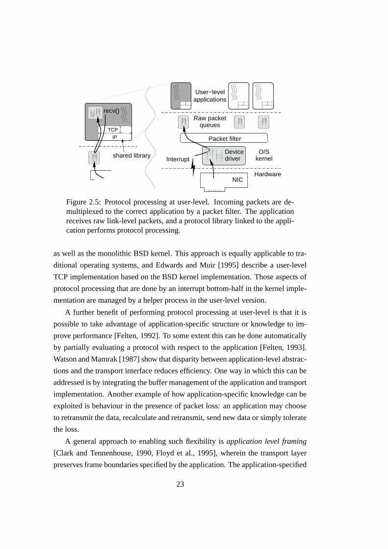
Figure 2.5: Protocol processing at user-level. Incoming packets are de-multiplexed to the correct application by a packet filter. The applicationreceives raw link-level packets, and a protocol library linked to the appli-cation performs protocol processing.
as well as the monolithic BSD kernel. This approach is equally applicable to tra-
ditional operating systems, and Edwards and Muir [1995] describe a user-level
TCP implementation based on the BSD kernel implementation. Those aspects of
protocol processing that are done by an interrupt bottom-half in the kernel imple-
mentation are managed by a helper process in the user-level version.
A further benefit of performing protocol processing at user-level is that it is
possible to take advantage of application-specific structure or knowledge to im-
prove performance [Felten, 1992]. To some extent this can be done automatically
by partially evaluating a protocol with respect to the application [Felten, 1993].
Watson and Mamrak [1987] show that disparity between application-level abstrac-
tions and the transport interface reduces efficiency. One way in which this can be
addressed is by integrating the buffer management of the application and transport
implementation. Another example of how application-specific knowledge can be
exploited is behaviour in the presence of packet loss: an application may choose
to retransmit the data, recalculate and retransmit, send new data or simply tolerate
the loss.
A general approach to enabling such flexibility is application level framing
[Clark and Tennenhouse, 1990, Floyd et al., 1995], wherein the transport layer
preserves frame boundaries specified by the application. The application-specified
23

data unit is used as the unit of error control and delivery for the low-level network
protocol. The motivation is to allow applications to process frames out-of-order,
so that presentation processing need not be held up when packets are lost.
Performing protocol processing at user-level has a number of disadvantages
in common with user-accessible network interfaces. They are described in sec-
tion 2.4.3.
2.3.3 Remote memory operations and RDMA
In the traditional network model, applications specify the source of a data trans-
fer in terms of a local buffer, and the destination in terms of an endpoint ad-
dress. The receiving system decides where incoming data is placed, and hence
this model is termed the receive-directed model. In the alternative send-directed
model [Wilkes, 1992, Swanson and Stoller, 1996], the initiator of the transfer also
specifies into which buffers at the receiver the payload should be delivered. The
principal advantage of this model is that the receiving system is always able to
deliver incoming packets. In the more common receive-directed model, the queue
or pool of receive buffers may be exhausted, in which case packets are usually
discarded.
Thekkath et al. [1994] propose constructing distributed systems using remote
memory operations. Operations are provided to read data from, or write data to
memory regions in a remote node. The remote memory regions are identified by a
segment descriptor. The operations are invoked by executing special co-processor
instructions, which are emulated in the kernel in the implementation described.
An advantage of this approach is that transfer of data and control are separated.
Remote DMA (RDMA) [Sapuntzakis and Romanow, 2000] allows a device to
read or write memory in another node without the intervention of the CPU in that
node. It is conceptually similar to a local DMA operation, except that the request
and data are forwarded across a network. This is useful for network attached I/O
devices, particularly storage devices [DAFS, 2001].
RDMA can also be used to transfer data between communicating processes.
For an RDMA write transfer, the payload is read out of host memory using DMA,
transmitted across the network and delivered directly into the receiving applica-
24

tion’s buffers by the remote line card. Efficient implementations of RDMA require
support in the line cards.
The proposed TCP RDMA option is an annotation for the TCP protocol that
allows the sender to identify segments of the TCP payload that should be deliv-
ered directly into application-level buffers [Sapuntzakis and Cheriton, 2000]. This
is particularly useful for protocols that transfer uninterpreted data interspersed
with headers, such as distributed file systems and HTTP. The RDMA option field
identifies the data, and an identifier indicates to which buffer the data should be
delivered.
RDMA read operations are also possible. The initiating node sends an RDMA
read request to the remote line card, which reads data directly from the specified
buffers and performs an RDMA write to transfer the data back to the destination
buffers. This requires that the line card be capable of handling the full transport
protocol, and hence is significantly more complex than RDMA write.
2.4 User-accessible network interfaces
A user-accessible network interface gives applications direct access to the net-
work hardware, removing the operating system kernel from the communication
path. This is illustrated in figure 2.6. User-accessible networks reduce overhead
and latency by eliminating system calls and interrupts on the common path, re-
ducing the number of times data is copied, and in some cases simplifying pro-
tocol processing. In addition, protocol processing is carried out at user-level, so
user-accessible networks have all of the advantages cited in section 2.3.2.
Only interfaces that provide protected communication in a multiprogrammed
environment are considered in this dissertation. As a minimum, a user-accessible
line card must multiplex requests from concurrent applications in a safe, protected
manner, and must demultiplex incoming data into applications’ receive buffers. A
user-accessible line card must necessarily maintain state relating applications and
network addresses with buffers in host memory. Consequently user-accessible
line cards are often more complex than those used in traditional architectures.
Many user-accessible network technologies provide guarantees beyond those
normally provided by the network. Some provide an reliable network abstraction:
25

O/Skernel
Devicedriver
recv()
Protection
NICMultiplexing
Per−endpointresource inthe line card
Hardware
Software
Figure 2.6: A user-accessible network interface. Each application has aprotected mapping onto the line card, and the line card has direct accessto the application’s communication buffers. Data path operations can becarried out entirely at user-level.
errors are detected by the line card, and retransmissions are handled in hardware.
Some short range interconnects have very low transient error rates, and can be
considered reliable, so no retransmission logic is necessary. Most guarantee to
deliver messages in order, and some provide end-to-end flow control. Applica-
tions can take advantage of such guarantees to reduce the complexity of protocols
implemented in software, and hence reduce overhead.
Networking support is not completely removed from the operating system ker-
nel; a device driver allocates resources on the user-accessible line card to applica-
tions, may handle out-of-band events, and is usually involved in connection set-up.
In multiprogrammed systems, applications must be able to block efficiently until
some network event happens. This means making a system call so that the kernel
can reschedule without waiting until the process’s time-slice expires.
Within each node, protection is achieved by two mechanisms. Firstly, each
application is given a virtual memory mapping onto a distinct portion of the line
card’s I/O address space. Secondly, the line card demultiplexes incoming data to
the correct applications, preventing applications from snooping data intended for
others. Pages of memory that contain buffers that may be accessed by the line
card are typically pinned to ensure that they are not swapped out by the virtual
memory subsystem.
26

virtual
mappingmemory
Application 1
RAM
Application 2
mappingLogical
Figure 2.7: Virtual memory-mapped communication: a form of dis-tributed shared memory in which a virtual address range in one applica-tion is mapped over the network onto physical memory in another node.
2.4.1 Distributed shared memory
User-accessible network interfaces have grown along two evolutionary paths. The
first type are shared memory network interfaces, and have come from large mul-
tiprocessors. The second are message-based network interfaces, which provide a
user-level interface to traditional packet networks.
Large shared memory multiprocessors typically consist of large numbers of
processors, each with local memory, connected by a high-speed interconnect.
Each processor can access all the memory through a single physical address space.
However, access to memory attached to other processors has relatively high la-
tency, and hence these machines are termed Non-Uniform Memory Architecture
(NUMA) machines. The Stanford FLASH multiprocessor is a notable example
that supports multiple protocols and flexible synchronisation with a dedicated pro-
tocol processor in each node [Kuskin et al., 1994].
It is a small conceptual step from this model to a network of workstations,
each with one or a few processors. In this case each node runs a separate instance
of the operating system, and has a separate physical address space. Distributed
shared memory enables applications in separate nodes to communicate using the
shared memory model.
There are a variety of architectures, but in the prevalent model, part of the
27

physical address space of a node is mapped over the network onto physical mem-
ory in other nodes. Part of the virtual address space of an application is mapped
onto part of the physical address range occupied by the line card. The line card
forwards memory accesses across the network to a remote line card, which reads
or writes physical memory in the remote node. This is illustrated in figure 2.7.
The line card simply performs mappings between I/O bus addresses and network
addresses, and encapsulates memory accesses in a network protocol.
Distributed shared memory as a transport for local area networks differs in a
number of important ways from multiprocessor interconnects. In a network, errors
or failures should be reported to the affected applications, not cause failure of all
nodes. Distributed shared memory may be addressed with a flat address space, or
with a structured scheme, such as {host,segment,offset}. Distributed shared mem-
ory is normally not completely transparent: a programming interface is provided
to set up mappings, perform error notification and provide support for synchroni-
sation. Cache coherence algorithms have high complexity and overhead, and thus
distributed shared memory networks often implement a less strict consistency, or
alternatively may not permit non-local caching.
Scalable Coherent Interface
An example of this model is the Scalable Coherent Interface (SCI), an IEEE stan-
dard [IEEE, 1992]. Although much of the specification deals with cache coher-
ence, implementations targeted at distributed systems (such as those developed by
Dolphin) are non-coherent [Ibel et al., 1997]. CPU load/store operations are not
expected to fail, so shared memory interfaces must ensure reliability at the hard-
ware level. To reduce host processor overhead for bulk data transfer, SCI provides
a DMA mechanism which moves large chunks of data between hosts.
Support for synchronisation is one way in which shared memory systems dif-
fer markedly. Data is written to (and read from) the shared memory without inter-
vention from the host processor, so there is no hook with which applications may
synchronise. The line card has no knowledge of the application-level protocol,
and thus cannot distinguish between memory accesses that correspond to inter-
esting events, and those that require no synchronisation. Applications may poll
28

the relevant memory locations, but this is an inefficient use of the host processor
if a message is not expected soon, and scales poorly as the number of endpoints
increases. Polling is used on clusters that are dedicated to a single task, or when
using gang-scheduling, but is not suitable on general purpose systems.
SCI allows the sending process to request an interrupt at the receiver, which
can be used for synchronisation. A problem with this scheme is that an interrupt
should only be needed if the receiver is blocked and needs waking, but the sender
has no way to know whether this is the case. To avoid races, an interrupt must
usually be delivered with each message, incurring high overhead. Ibel et al. [1997]
found this to be very expensive, so resorted to polling only.
SHRIMP VMMC
Virtual Memory Mapped Communication (VMMC) is a network interface for the
SHRIMP multicomputer developed at Princeton. It is a shared memory interface
built with custom hardware, and an off-the-shelf routing backplane. It differs from
SCI in that regions of physical memory in one node are mapped onto physical
memory in another. That is, updates to the local memory are forwarded to the
remote memory. It provides two modes of communication.
1. Automatic update
Stores to a mapped region of memory are snooped by the network interface,
and propagated to the corresponding locations in a remote node.
2. Deliberate update
Stores to the mapped region are not automatically sent to the remote node.
The application must ask the network interface to transfer a portion of a
mapped region by DMA.
Each page of mapped memory has an associated command page, which is a
virtual mapping onto the network interface hardware. To transfer n bytes starting
at location l, the application writes the value n to the command page location
corresponding to l. Since the DMA engine may be busy (and only supports one
request at a time), a compare-and-exchange instruction is used to check whether
the DMA engine is free and initiate a transfer in a single atomic step. Thus DMA
29

transfers are initiated at user-level with only a single instruction. Note however
that this instruction will take many clock cycles since it makes a read to I/O space,
and the process may have to retry multiple times if the DMA engine is busy.
In addition a great deal of virtual address space is consumed, which degrades
performance because the TLB miss rate is increased.
The atomic compare-and-exchange instruction can only be used where the
network interface is directly attached to the system bus. Blumrich et al. [1996]
describe an alternative that uses separate store and load instructions, but requires
the operating system kernel to inform the line card of context switches. Markatos
et al. [1997] describe a further refinement that uses context keys so that special
kernel support is not needed.
VMMC-2 [Dubnicki et al., 1997] is the second generation network interface,
and is implemented using Myrinet. Automatic update is not supported in this
implementation, because the Myrinet line card is not able to snoop PIO stores
(whether to host memory or to its on-board SRAM). Whereas VMMC has a fixed
mapping between source and destination buffers, VMMC-2 is more flexible. A
user-managed TLB (UTLB) identifies buffers in an application’s address space
that are pinned, and hence may be accessed by the line card. It is stored in
host memory, with a cache on the line card to reduce latency. Each send and
receive request consults the UTLB, and invokes the device driver to add entries
for send/receive buffers that are not already registered.
A further improvement is transfer redirection, wherein incoming data may
temporarily be directed to an alternative buffer. If the application invokes a re-
ceive operation before the data arrives, a suitable redirection allows the data to
be delivered directly into the application-specified buffer. If no redirection is re-
quested, data is delivered to a default buffer, and must be copied into the appli-
cation’s receive buffer when it invokes the receive operation. Transfer redirection
was shown in [Dubnicki et al., 1997] to substantially improve throughput on a test
system, but it was a system with very poor memory-to-memory copy performance
compared with more modern systems.
In order to support blocking synchronisation, the application may request that
the line card raise an interrupt when a particular page of local memory is accessed.
This is an improvement on the SCI scheme, as it puts the receiver in control of
30

synchronisation. Reliable data transfer is guaranteed: Myrinet already has a very
low transient error rate, and this is backed up with a per-node retransmission queue
in each line card.
Other distributed shared memory interfaces that are similar to those described
above include Memory Channel [Fillo and Gillett, 1997] and Telegraphos [Markatos
and Katevenis, 1996]. Both additionally support multicast, and atomic operations
on remote memory which can be used for synchronisation.
All of these networks share host memory. Memnet however, shares memory
that resides in the line card [Delp et al., 1988]. Each page of memory has a fixed
home location, but may be cached at other nodes. Disadvantages of this approach
are that host memory is typically cheaper and more plentiful than memory on net-
work devices, and the cost of accessing memory over the I/O bus is high compared
with the cost of delivering data into host memory by DMA.
2.4.2 Message-based interfaces
Message-based user-accessible interfaces have been developed to improve the per-
formance of applications on local or system area networks. Early examples are
described in [Davie, 1993] and [Thekkath, Nguyen et al., 1993]. Packets in such
networks are addressed to endpoints, which typically have addresses of the form
{host,port}. The line card may either expose an interface to send and receive link-
level packets, or may have a higher-level message-based interface. Applications
form messages or packets in user-level buffers, and invoke the line card to trans-
mit them onto the network. Incoming messages are demultiplexed by the line card
into user-level buffers, and some mechanism is used to notify the application that
a message has been delivered. Message-based interfaces are similar to traditional
kernel-managed interfaces: each application is given direct access to one or more
send and receive DMA rings.
As with shared memory interfaces, data is delivered into user-level buffers
without intervention from the CPU. In this case, however, the line card is party to
the protocol being used, and may perform a suitable synchronising action such as
raising an interrupt as necessary.
31

U-Net and VIA
The goals of U-Net were to provide near link latency, achieve full network band-
width with small messages, and facilitate use of novel protocols [von Eicken et al.,
1995]. These goals are achieved by removing the kernel from the critical path, and
putting buffer management under the control of the application. Two implemen-
tations using off-the-shelf hardware are described: an ATM controller with an
on-board processor is directly accessible at user-level, whereas for a less sophis-
ticated ATM controller the U-Net interface is emulated in the kernel. U-Net has
also been demonstrated on Fast Ethernet [Welsh et al., 1996].
The network interface is queue-based. To send a message, the application
composes the message in a buffer, constructs a descriptor that describes the buffer
and gives the destination, and places the descriptor on the send queue. Incom-
ing messages are demultiplexed into buffers provided by the application in a free
queue, and as each message is received a descriptor is placed on a receive queue.
The application may poll the receive queue, register a callback, or block wait-
ing for messages to arrive on one or more queues with the Unix select system
call. Small messages can be stored in the descriptors themselves, which simplifies
buffer management and reduces latency.
The direct access version of the architecture adds an RDMA write facility,
which permits the application to specify the location in the receiver at which
the payload will be delivered. In addition, message payloads (other than RDMA
writes) may be placed anywhere in an application’s address space. Welsh et al.
[1997] describe an implementation with a TLB on the line card, which is kept
consistent with the kernel’s page tables. Pages that are mapped by the TLB on the
line card are not eligible for swapping. However, the problem of how to deliver in-
coming data to addresses that are not resident in RAM is not handled completely.
It is assumed that all data in a page will be overwritten, so its contents are not
copied back in from the swap device.
The Virtual Interface Architecture [VIA, 1997] is an industry standard that
formalises some of these ideas from academic research. It presents a similar com-
munication model to U-Net, based on queues of send and receive descriptors. It
also has the RDMA write primitive, and adds RDMA read. Unlike U-Net, it is
32

connection oriented: there is a one-to-one mapping between connected endpoints,
so descriptors need not contain endpoint addresses. VIA is discussed in detail in
chapter 5.
Arsenic
Arsenic is a user-accessible network interface designed to improve the perfor-
mance of existing protocols on packet networks such as Ethernet [Pratt and Fraser,
2001]. It is implemented using an off-the-shelf programmable line card designed
for protocol offload. Arsenic gives applications direct access to the payload of
link-level Ethernet frames, and processing of higher level protocols (TCP and
UDP) is carried out at user level. Like U-Net, the interface is based on queues of
descriptors.
Packets are demultiplexed using filters uploaded to the line card by the kernel.
Outgoing packets are validated against a template, in order to prevent applications
from masquerading or violating key protocol requirements. In addition, traffic
shaping is supported: a packet scheduler ensures that in-credit flows are treated
fairly, and traffic is smoothed. Together with the early demultiplexing of packets,
this ensures good separation of flows, minimising cross talk. The performance
of latency sensitive applications in the presence of competing bulk transfers is
substantially improved.
Like the user-level TCP/IP described by Edwards and Muir [1995], a dedicated
thread is employed to perform the work usually done by the interrupt handler in
a kernel implementation. Applications may request that an event be delivered
when the receive queue contains at least n entries, or has been non-empty for a
specified period. This is implemented by raising an interrupt and delivering a
signal. Only one such event may be outstanding for each application. This limits
the number of interrupts an application can generate, and hence the amount of time
the application may cause to be spent beyond the control of the system scheduler.
It is not made clear how the application can use this to wait on multiple endpoints.
33

Hamlyn
Hamlyn provides a send-directed model much like RDMA write, with the receiver
explicitly notified about each incoming message [Buzzard et al., 1996]. Together
with the assumption of a reliable network, Hamlyn’s send-directed model ensures
that messages can always be delivered. Hamlyn supports networks that may de-
liver packets out of order, and can therefore benefit from the increased throughput
achieved by adaptive routing networks.
Message areas are pinned regions of memory that contain transmit and receive
buffers. They are identified by slots which may be exported to the sender. Each
slot has an associated 64 bit protection key, which is checked before messages are
delivered. This ensures that receive buffers cannot be overwritten by unauthorised
applications or faulty nodes. Messages may also contain out-of-band data, which
is deposited in a separate buffer.
A stated goal was that “Hamlyn should be simple enough to be implementable
using hardware state machines, since programmable controllers are often slow.”
However the model is arguably significantly more complex than distributed shared
memory type networks. For the Myrinet implementation given by Buzzard et al.
[1996], the programmable controller on the line card contributes half of the total
latency for small messages.
2.4.3 Disadvantages of user-accessible interfaces
Whilst user-accessible networks have achieved significant improvements in per-
formance over other models, they come at a cost. This section outlines the dis-
advantages and trade-offs associated with user-accessible technologies, and per-
forming protocol processing at user-level.
• User-accessible line cards are typically substantially more complex, and
therefore more expensive than traditional line cards. The complexity arises
from the need to provide multiple protected interfaces, manage per-endpoint
state, and perform demultiplexing. Some user-accessible line cards also do
higher-level protocol processing.
34

• The number of applications and clients that can be supported simultane-
ously is limited by the resources on the line card. In traditional networks
the number of endpoints is limited only by host memory, which is compar-
atively very cheap. Some line cards also keep state relating to each node
in the network, which may limit the scalability of the network as a whole.
VMMC-2, for example, keeps one retransmission queue per node in the
network.
A solution to this problem is to virtualise per-endpoint resources: a working
set of endpoints are kept on the line card, with state for all other endpoints
in host memory. The kernel’s page fault handler is used to move an end-
point back into the line card when it is accessed by the application. Note
however that enough information must be kept in the line card to deliver in-
coming packets, or alternatively sufficient buffering to hold the packet until
the endpoint’s state is restored.
• Protocol processing is stalled if the process is otherwise blocked. For ex-
ample, the host processor sits idle while a process is blocked on disk I/O,
even if data has arrived at one of the application’s network interfaces. In the
traditional model the packet would be processed by the interrupt handler on
delivery. This can be worked around with extra threads or signals, but it
is hard to make this work transparently for existing applications. Note that
this criticism also applies to the lazy receiver processing model.
• Many system utilities rely on the system call hook. For example, the Unix
ptrace interface permits one process to monitor or control another by inter-
cepting system calls. Intercepting network I/O in this way is not possible
when a user-accessible line card is used.
• The flexibility of protocol processing at user-level may come at the expense
of ease of management. Networking is no longer managed by a single entity
(the kernel) but potentially in many applications and libraries. There is no
longer a single interface for monitoring, accounting and management of
policy.
• One of the main purposes of the operating system is hardware abstraction.
35

User-accessible network interfaces require that hardware-specific code be
executed at user-level. It can be encapsulated in dynamically linked sys-
tem libraries, but there is no standard mechanism for this on existing Unix
systems, and different solutions tend not to work well together.
2.5 Managing multiple endpoints
Servers are increasingly required to support large numbers of concurrent clients.
Since network I/O may block for an arbitrary length of time, servers must manage
clients concurrently to maximise throughput and prevent any one client from hold-
ing up progress. Perhaps the simplest way to do this is to fork a separate process
to handle each client, with the scheduler choosing another process to run when
I/O causes the running process to block. To reduce the cost of context switches
and simplify sharing of state, threads may be used instead of separate processes.
This model has limited scalability, however, as processes and threads are typically
limited resources, and some schedulers perform poorly when many processes are
runnable.
An alternative is the single-threaded event-driven model. Non-blocking I/O
is used to ensure the server is not held up while processing any individual client.
The interaction with each client is represented by a state machine which is driven
by up-calls from an event processing loop. This model is harder to use because
it inverts the programming model: I/O drives the thread of control rather than
the other way around. However, it puts the application in control of scheduling
between clients, and typically performs better at high load than thread-per-client.
In order to take advantage of multi-processors, a number of threads may be used,
each handling a share of the clients.
Operating systems provide interfaces to inform an application which of a set of
endpoints are ready for I/O, or to block if none are. The best known mechanisms
are the Unix select and poll system calls. The endpoints can be files, IPC endpoints
or other devices as well as network sockets. There are two classes of interface:
1. State-based interfaces report whether or not receiving and sending from and
to the endpoint will block. For network sockets this translates to whether
36

data is available for receiving, and whether there is buffer space available
for sending. Exception conditions are also reported.
2. Event-based interfaces report changes in the state of an endpoint. This is
potentially more efficient, since it is presumably changes in state that the
application is interested in. However, such interfaces are fragile compared
with state-based ones: it is difficult to avoid subtle race conditions, and if
an event is missed, an application may neglect a client indefinitely.
The select mechanism has been shown to scale poorly with increasing num-
bers of connections, even when aggressively optimised [Banga and Mogul, 1998].
The problem is that the cost of a call to select necessarily grows linearly with
the number of endpoints, as the application must specify the set of interesting
events each time. Performance is particularly bad if many endpoints are idle:
each endpoint may be polled many times for each unit of useful work done, and
the overhead due to select approaches the square of the number of endpoints. Due
to slow dial-up links and congestion, it is common for Internet servers to man-
age large numbers of connections that are idle for much of the time [Banga and
Mogul, 1998].
The poll system call is also state-based, and has the same limitations as select,
but can be more efficient if the set of endpoints is sparse in the descriptor space.
The /dev/poll interface is a refinement that permits the application to register its
interest set incrementally in advance. This reduces overhead because the appli-
cation need not repeatedly restate its interest set each time it requests the current
state.
A number of event-based interfaces have been proposed and implemented. On
many Unix systems it is possible to configure a socket to deliver a signal to the ap-
plication when an I/O event occurs. If POSIX realtime signals are used, the event
notifications can be queued rather being delivered via a preemptive signal handler,
and the notification identifies the socket that generated the signal. Queued POSIX
realtime signals have been shown to be efficient compared with other mechanisms
under Linux [Chandra and Mosberger, 2001].
Banga et al. [1999] propose an event-queue based system for Unix systems
that allows applications to register interest in events on particular endpoints. It
37

improves on POSIX realtime signals by reporting the current state of an endpoint
when registering interest. This helps to avoid a race condition when a new con-
nection is registered. Multiple events can be dequeued with a single system call,
reducing overhead.
A serious problem with some interfaces that queue events is that the queue
can overflow. If this happens the application has to resort to polling the endpoints
using a state-based interface. This is most likely to happen when the server is
overloaded, and switching to a less efficient mechanism causes performance to
collapse. Further, designing an application to use two mechanisms is wasteful
and hard. Chandra and Mosberger [2001] suggest modifying the POSIX realtime
signal queue so that only one event from each endpoint may be enqueued at a
time, thus preventing overflow.
Another technique to avoid blocking is asynchronous I/O. In this model the
application makes I/O requests which complete asynchronously. This improves
concurrency because the application need not block, and saves the application
from having to determine in advance whether an endpoint is ready for an I/O op-
eration. Asynchronous I/O more closely matches the way I/O hardware behaves,
and is the model supported by the low-level interface of most user-accessible line
cards. Unfortunately many existing implementations for kernel-managed I/O are
inefficient.6
2.5.1 User-accessible networks
Some user-accessible network interfaces have provided their own interfaces for
managing multiple endpoints. The VIA specification describes a completion queue
to which connections may direct events. It is intended to be a user-accessible re-
source, and potentially has low overhead, but is susceptible to overflow.
The Hamlyn interface has a notification queue which is also susceptible to
overflow. It is assumed that communicating processes will cooperate to prevent
this from happening. When communicating with untrusted peers a paranoid one-
shot mode can be used, where only one message is accepted from each connected
6Most implementations of asynchronous I/O are user-level wrappers for synchronous I/O usinghelper threads, and therefore incur extra context switches. An efficient implementation requiressupport in the kernel.
38

peer before it is acknowledged. This bounds the size of notification queue needed
to avoid overflow, at the expense of additional overhead and restricted semantics.
However, applications using user-level networks still need to use other O/S
resources such as files and pipes or sockets for inter-process communication. In
order for user-accessible technologies to integrate well with these resources they
need to support the standard interfaces. U-Net is integrated with the select mech-
anism so that applications can perform a homogeneous wait on U-Net and other
endpoints. Most other user-accessible networks do not appear to have addressed
this problem.
2.6 Summary
The performance of applications on high-bandwidth local area networks is limited
by host processing overheads and memory bandwidth in the end systems. High
overhead limits the achievable bandwidth, latency and transaction rate. High per-
message overheads limit the performance of small messages, which are common
in practice.
User-accessible network interfaces address this problem by reducing the over-
heads associated with interrupts, context switches and in-memory buffer copies.
By demultiplexing incoming data in the line card and avoiding interrupts, they
also avoid the QoS cross-talk incurred by the traditional network architecture.
Performing protocol processing at user-level has a number of benefits, not least
the ability to exploit application-specific knowledge to improve efficiency.
Distributed shared-memory based interfaces are very low-level, and hence
flexible. The simplicity of the interface permits highly efficient implementations
with very low latency and overhead. Message-based interfaces provide a higher
level of abstraction, and semantics that may be closer to those required by some
applications, but at the expense of flexibility. It is possible to implement mes-
sage passing on top of shared memory and achieve high performance [Ibel et al.,
1997], whereas software distributed shared memory over messaging incurs high
overhead and requires support in the kernel.
There are numerous application-level network abstractions, and a variety of
architectures for applications managing large numbers of clients. If new tech-
39

nologies are to support existing applications without substantial modification, it is
important to have flexible and efficient data transfer and synchronisation. The next
chapter presents the CLAN network, which, it is argued, exhibits these desirable
properties.
40

Chapter 3
The CLAN Network
The Collapsed LAN (or CLAN) project at AT&T Laboratories–Cambridge was
born of an idea by Maurice Wilkes to move all but the user interface of desk-
top systems into a machine room [Wilkes and Hopper, 1997]. The workstations
would then be physically close to one another and to the servers, and could be
connected by a high performance system area network. The workstations were to
be connected to the users’ terminals by dedicated fiber links. Advantages of this
approach include potentially improved network performance, reduced noise in the
office, centralised maintenance and cost savings.
The project initially addressed the interconnect between the workstation clus-
ter and terminals [Hodges et al., 1998], but it was soon realised that the technol-
ogy they had developed was applicable to general purpose local area networking.
The project moved toward the implementation of a high performance local area
network suitable for general purpose distributed systems, and scalable to large
numbers of applications and endpoints.
This chapter provides a detailed description of the CLAN network model and
prototype implementation, and an analysis of its features. It provides the context
in which the work described in subsequent chapters was performed. The raw
performance of CLAN is analysed, and the PIO and DMA mechanisms for data
transfer are compared.
41

3.1 Data transfer model
The CLAN network is a shared memory network, using host memory rather than
auxiliary memory in the network. As in SCI, a region of physical memory in
one node is mapped into both the address space of a local application, and that
of an application in another node on the network (see figure 2.7). Applications
communicate through the shared memory.
A region of memory that is exported to other nodes in the network is known
as a local aperture. It is identified by a descriptor called an RDMA cookie, which
may be passed to other nodes in the network. An RDMA cookie is like a weak
capability which grants an application access to a region of memory in another
node. Applications may create virtual mappings onto the memory region identi-
fied by an RDMA cookie, and such a mapping is known as an outgoing aperture.
Applications may also ask the line card to perform an RDMA write to transfer
data from local buffers to a memory region identified by an RDMA cookie and
offset, thus reducing overhead for large transfers.
CLAN is primarily intended to support the send/receive model of traditional
networks rather than the shared memory programming model. The purpose of
caches and cache coherency protocols in workstations and multiprocessors is to
attempt to keep data close to where it is needed, in the absence of perfect informa-
tion. However, where shared memory is used for data transfer, the best place for
the data is known: at the receiver. Thus CLAN does not permit caching of mem-
ory at remote nodes, and data stored to an outgoing aperture is forwarded imme-
diately to the remote memory. Loads from outgoing apertures incur a round-trip
delay, and therefore have high latency and overhead. No management of cache
coherency is needed in the network, permitting a simple and efficient implemen-
tation.
3.1.1 Properties of the shared memory
In order to put the following discussion in context, a simple message passing
protocol is illustrated in figure 3.1. The sender has a virtual mapping onto the
buffer in the receiver. Access to the buffer is controlled by the two flags: tx ready
42

tx_ready
Messagebuffer
rx_ready
Local aperture(host memory) (virtual mapping)
Outgoing aperture
Sender Receiver 1 int sm write(void* message, int size )2 {3 if ( ! tx ready ) return NOT READY;4 tx ready = 0;5 memcpy(message buffer, message, size );6 WRITE BARRIER();7 rx ready = 1;8 return 0;9 }
Figure 3.1: Simple message transfer with CLAN
and rx ready. When tx ready is set, the sender writes a message into the receive
buffer and sets tx ready to zero. rx ready is then set to indicate that the receive
buffer contains a valid message. When the receiver has read the message, it sets
rx ready to zero and sets tx ready to allow the sender to transmit another message.
Loads from outgoing apertures are not cached, and therefore incur high over-
head and latency. The data and control variables are therefore partitioned so that
no such loads are necessary. Local apertures are cacheable however, so the re-
ceiver can access and manipulate the message payload efficiently. Spinning (re-
peatedly polling control variables) is efficient, since it generates no traffic on
the system bus until the control variables are overwritten. This model assumes
a cache-coherent I/O subsystem, so that memory locations that are overwritten by
the line card are invalidated in host processor caches.1
If a zero-copy programming interface is used on the send side, messages can
be formed directly in the remote receive buffer. Transferring small messages in
this way consists of just a few processor store instructions. As noted above, care
must be taken to avoid loads from outgoing apertures, which may be non-obvious
at the programming level. For example, an unaligned store typically causes the
two words to be loaded, modified and stored back.
On the receive side, message delivery is asynchronous, and incurs no overhead
on the host processor. The message body may be copied into an application-level
1Druschel et al. [1994] describes a technique to reduce the cost of partial cache invalidationson systems that do not have cache-coherent I/O.
43

buffer, or the application may access the receive buffer in-place with a zero-copy
interface.
The CLAN network guarantees not to reorder memory accesses between two
nodes, and hence the shared memory is PRAM consistent. This is defined by
Lipton and Sandberg [1988] as follows:
“Writes done by a single process are received by all other processes
in the order in which they were issued, but writes from different pro-
cesses may be seen in a different order by different processes.”
Note that while CLAN does not reorder memory accesses, super-scalar host
processors may. The programmer must make appropriate use of memory barriers
to guarantee the ordering when it matters.
3.1.2 Connection management
CLAN also supports small out-of-band messages that are addressed to an endpoint
identified by a port number. They are not interpreted by the network and may be
used for any purpose. CLAN is not connection-oriented at the network level, but
most application-level network abstractions are. Out-of-band messages are there-
fore used to manage connections. Messages used to negotiate new connections
typically contain one or more RDMA cookies that identify the buffers that will be
used for the subsequent transfer of data. Out-of-band messages are also used to
tear-down connections and report errors.
3.2 Synchronisation: Tripwires
As stated in section 2.4.1, synchronisation in shared memory networks is diffi-
cult because the line card has no knowledge of the shared memory protocol, and
so does not know when an “interesting” event has happened. CLAN solves this
problem by allowing the application to specify which memory locations are inter-
esting. Tripwires provide a means for applications to synchronise with accesses to
particular locations within their shared memory. Each tripwire is associated with
44

some memory location, and fires when that memory location is read or written via
the network. In response, a synchronising action is performed.
Crucially, tripwires are programmed by applications. An application can set
up a tripwire to detect accesses to a particular memory location in its own address
space, and will be notified when that location is written by another node. The
application will choose a memory location which corresponds to some interesting
event in the protocol it is using.
Tripwire matching happens in the line card, which maintains a table of the
logical addresses to be matched and corresponding synchronising actions. These
logical addresses consist of the aperture and offset that identify the memory lo-
cation that the application has selected. As network traffic passes through the
line card, the logical address of each word of data is computed and the table is
searched. When a match is found, the corresponding synchronising action is per-
formed. This might be to set a flag, deliver an event notification, or wake an
application which is blocked.
In the example given in figure 3.1, the receiver might set a tripwire on the
rx ready flag, which is set when a message is available in the receive buffer. The
receiver can then use this tripwire to block until a message arrives: it initialises
and enables the tripwire, then makes a system call to request that it block until the
tripwire fires. Similarly, the sender might use a tripwire on the tx ready flag to
block until the buffer is available for another message. The synchronising action
in these cases would be to generate an interrupt, which would enable the device
driver to wake the applications.
3.2.1 Properties of tripwires
Tripwires are fine-grained
A tripwire is associated with a single memory location, so applications can detect
specific protocol events. In contrast with schemes that operate on the granularity
of a page, accesses to memory locations that do not require synchronisation (such
as acknowledgements) are ignored. Applications can also support multiple inde-
pendent endpoints on a single page. Applications only receive notifications for
events in which they are interested, minimising overhead.
45

Tripwires are flexible and efficient
Tripwires can be used to detect reads or writes by remote nodes. An application
can synchronise with the arrival of a message, or with a remote application having
read a message from its address space (so it knows when it can reuse the buffer).
It is possible to synchronise with accesses to meta-data such as flags or counters,
or with the message payload itself.
Tripwires can also be used to detect reads or writes by local processes to mem-
ory in other nodes. This might be used to detect the completion of an outgoing
RDMA transfer, or for synchronisation between threads.
Synchronisation is orthogonal to data transfer
No explicit support for synchronisation need be added to data transfer protocols.
The use of tripwires is local to a node, and so adds no overhead in the network.
Tripwires may be used to synchronise with any shared-memory protocol, provided
that protocol-level events can be identified by accesses to particular memory loca-
tions. This is likely to be the case for any practical protocol, since this requirement
is also necessary (but not sufficient) to support a polled mode of operation.
Synchronisation is decoupled from the remote endpoint
The sender does not need to do anything special to inform the receiver of the
arrival of a message. This reduces complexity and overhead at the sender. The
receiver decides whether it needs to synchronise, and how it is to be done. Ex-
plicit notification is usually only needed when an application wants to block, or is
managing many endpoints.
Early wakeup
Between a memory access and the application receiving a notification there is a
gap in time which contributes to latency. It may be large if the application has
blocked and has to be rescheduled. In this case the application may choose to
synchronise with a protocol event that is known to precede the event of interest.
For example, the application waiting for an incoming message may synchronise
46

Figure 3.2: The CLAN prototype line card
with a write to a memory location that is part of the way through the message,
rather than at the end. The reschedule then proceeds in parallel with the arrival of
the trailing portion of the message, reducing latency. This optimisation depends
on knowledge of the order in which message data is to arrive, and needs tuning on
different machines.
3.3 Prototype implementation
This section gives a detailed description of the prototype line cards and switches
developed by the CLAN team. Figure 3.2 shows a prototype line card, and fig-
ure 3.3 a schematic. The prototypes are based on off-the-shelf parts, including an
Altera 10k50e FPGA clocked at 60 MHz, a V3 PCI bridge (32 bit, 33 MHz) and
HP’s G-Link optical transceivers with 1.5 Gbit/s link speed.
3.3.1 DMA
The V3 PCI bridge chip includes an integrated DMA engine, which can be pro-
grammed to copy data from local buffers to the transmit FIFO. It was not designed
with user-level networking in mind, and so can only be accessed by the device
driver. Unfortunately it can only be programmed with a single request at a time,
and generates an interrupt after each transfer. This enforces a large gap between
each transfer, which limits throughput for small messages, and necessarily incurs
high overhead.
47

DMAEngine
V3 PCI Bridge
CAM
CAM
CAM
Tripwire
control
i960 Local Bus
TX fifo Read Control Write FIFOError FIFO
PCI Bus
Protocol anderror control
Fibre optictransceiver
TX mux RX demux
Protocol
interrupt
Figure 3.3: Schematic of the CLAN line card
3.3.2 Link layer protocol and switch
The network uses a novel link layer protocol that has a number of advantages over
existing protocols used in local area networks. Data packets resemble write bursts
on an I/O bus such as PCI, or a multiprocessor interconnect [Culler and Singh,
1998]. The header of a data packet identifies the target address for the payload,
consisting of the node, and a logical address. Notably, the size of the payload
is not encoded in the header, but is implicit in the framing of the packet. This
encoding has a number of desirable properties:
1. A line card or switch can begin to emit a packet as soon data is available
at the output port – even before the length of the packet is known. This
minimises latency and permits worm-hole routing in switches.
2. It is trivial to split a packet in two – the first packet is simply terminated,
and a new header generated for the trailing portion of data. The new header
will differ only in the target address, which is trivial to calculate.
3. Consecutive packets that represent a contiguous burst of data can be merged.
It is possible to determine if two packets can be merged by inspecting their
48

headers, and they are merged simply by chopping the header off the second
packet.
Neither splitting nor merging of packets requires whole packets to be buffered.
All that is needed is that the implementation keep track of the network address of
the packet data it is currently processing, by recording the address given in the
packet header, and incrementing it as the payload is processed.
The switch
Network switches are required to deliver some degree of fairness to the traffic
that passes through them. Large packets should not be able to hog an output
port unfairly. In most existing networks packets cannot be fragmented at the link
layer, and so packet size must be limited in order to achieve reasonable fairness at
switches.2
However, in the CLAN network packets can be split at any point, and with-
out knowledge of the whole packet. This feature is used in the CLAN switch to
provide fair arbitration without limiting packet size. An arbiter controls access to
output ports. When an incoming packet is granted access to the switch fabric, it
may transfer up to a maximum amount of data, the switch arbitration block size.
If the packet exceeds this limit, the arbiter may grant access to another input port
and the packet will be split as described above. When there is no contention, there
is no limit to the size of packet that can pass through the switch.
The switch arbitration block size, together with the number of ports on the
switch, determines the maximum jitter that can be experienced by traffic passing
through. At worst, a packet will have to wait for a switch arbitration block to go
through from each other input port before it gets access to the output port. Since
the switch arbitration block size is small (512 octets) and there are only five ports,
jitter is limited to just 16.4 µs per switch on the prototype network.
4 ports ∗ 4096 bits
109 bits per sec= 16.4 µs
For larger switches this bound will not be so tight, and applications must in
2Packet size may also be limited for other reasons, including fixed size buffers.
49

any case compete for the bandwidth available on loaded links. To support more
sophisticated quality of service guarantees some means to share out bandwidth is
also needed. One possible solution is the virtual lanes concept used in Infiniband
[Infiniband, 2000].3 Where the relative priority of competing packets is known,
the ability to split packets would allow a high priority packet to preempt a com-
peting lower priority packet that is already on the switch, achieving even lower
jitter.
The prototype implementation of the switch is based around a non-blocking
crossbar switch fabric. Each of the five ports is managed by an FPGA which
shares much of its logic with the line cards. Another FPGA is used for control
and arbitration. The switch is worm-hole routed, meaning the head of a packet
may be emitted from an output port even before the tail of that packet has arrived
at the input port.
Flow control
Flow control is rate-based on a per-hop basis: the rate at which the transmit-
ter sends depends on the amount of space available in the receiver’s FIFO. Back
pressure through the network limits the rate of the sender to that of the receiver.
The link-level flow control information is passed in-band with packet data. This
ensures that the required changes in flow rate are communicated to the sender with
very low latency, so the transmit rate can be adjusted to prevent buffer overrun in
the receiver.
The size of the receive-side buffers required to prevent buffer overrun is pro-
portional to the product of the link speed and latency of flow control information.
The receive FIFOs in the prototype implementation were limited by the available
space on the FPGAs to just to 512 octets. The low latency of flow control informa-
tion passed in-band with packet data was found to be essential in achieving stable
operation at full link speed.
Like all switched networks, CLAN is susceptible to head-of-line blocking,
wherein a congested link between two switches may hold up traffic that is des-
tined for an uncongested output port. This is only partly mitigated by the switch
3This was partially implemented in the CLAN prototype, but not completed.
50

arbitration scheme. The only solution to this problem is end-to-end flow control,
such as the credit-based scheme used by the Memory Channel network.
Addressing and routing
The CLAN network is packet-switched, so there is no per-connection state in the
network. The switches can either operate in a source-routed mode, or using static
routing tables. Topology is discovered using a tool which programs the routing
tables in the device driver or switches. Host addresses are 32 bits, and the standard
Internet Domain Name System is used for address lookup.
Discussion
The link layer protocol described above leads to a network with the following
properties:
Latency is minimised.
In the absence of congestion, switches and line cards begin to emit packets
as soon as the first word of packet data is available. For a 512 octet packet
on a 1 Gbps network with two hops, this saves about 8 µs compared with a
store-and-forward implementation.
Buffering requirements within the network are small.
There is no need to buffer entire packets at any stage in the network. The
size of buffers needed is determined by the line speed and latency of link-
level flow control, which is very low.
The network imposes no limit on packet size.
This is a consequence of not needing to buffer entire packets, passing link-
level flow control in-band with packets, and the switch being able to split
packets as needed.
Jitter introduced by switches is limited.
The maximum jitter introduced by each switch is bounded, and depends
51

only on the number of ports and switch arbitration block size. Where pri-
ority information is available, high priority traffic may preempt low priority
traffic.
In the current implementation, the I/O bus speed and link speed happen to be
closely matched. On implementations where the link speed exceeds the I/O bus
speed, the source line card will tend to emit many short packets, even though they
represent a single logical transfer. This would appear to reduce the efficiency of
the network, but in practice these packets will be merged at the switch if conges-
tion is encountered, or at the destination line card if the transfer rate is limited by
the destination system’s I/O bus. Where no congestion is encountered, the large
number of small packets have no detrimental effect.
However, the fragmenting of packets at switches does reduce efficiency on the
output link due to increased packet header overheads. A congested link will tend
to contain packets whose size is limited by the switch arbitration block size, with
packets from different flows interleaved. Thus there is a trade-off between jitter
and efficiency which is tuned by choosing the switch arbitration block size.
3.3.3 Zero-copy
Many network implementations claim to support zero-copy. In practice this term
usually means “No more copies than are required by the architecture.” For a
traditional network architecture, zero-copy often means the message data is only
copied between buffers in host memory once on the transmit path, and once on the
receive path. User-level networks provide the opportunity for the line card to read
message data directly out of an application’s buffers, and deposit it in user-level
buffers at the receiver. This is often termed “true zero-copy.”
The shared-memory network model permits a further improvement: messages
may be formed directly in the remote user-level receive buffer by writing into a
virtual memory mapping. Perhaps this should be known as “honest to goodness
zero-copy.”
The benefit of zero-copy receive has been overstated in many studies. A single
copy has the side effect of bringing data from host memory into the cache, so
decreasing overhead due to cache misses when the application comes to use the
52

a40aincremented foreach word of data
matches
a408 a409
a408
fc04
a408
fc04
a408
fc04
D A T Aa408 EH L L Ofc00
Addressregister
Data packets
Match!
FIFO containing
Pipelined CAMs
Figure 3.4: The mechanism of tripwire matching
data. Thus the measured cost of the copy alone is very much higher than its effect
on overall performance. The benchmarks used in many studies have failed to take
this into account because they do not ‘touch’ the data, so it is never brought into
the cache in the zero-copy experiments [Pratt and Fraser, 2001]. This can make a
dramatic difference: for example, peak TCP throughput for Trapeze on Myrinet-
2000 drops from 2 Gbit/s to 1.18 Gbit/s when the data is touched at both ends
[Chase et al., 2001].
Message copies may also occur in the network hardware. Many networks
buffer whole packets in line cards and/or switches. For example, on Myrinet all
data must be staged in SRAM on the line card. As well as increasing latency, this
necessarily introduces a latency/throughput trade-off [Yocum et al., 1997]. CLAN
does not suffer from any such trade-off because it does not buffer whole packets
at any point in the network.
3.3.4 Tripwires
The tripwire synchronisation primitive is implemented by a content addressable
memory (CAM). Figure 3.4 illustrates how tripwires are matched. The matching
logic snoops the line card’s internal bus for data packets. When the header of
a packet is encountered, the destination address of the payload is recorded in a
53

register, which is incremented as each word of data in the packet passes. Each
address is looked up in the CAM. When a match is found, the index of the entry
in the CAM is put in a FIFO, and the host processor is interrupted. In the interrupt
service routine, the device driver retrieves tripwire matches from the FIFO. For
each match it determines which application owns the tripwire and notifies it. If
the application is blocked waiting for the tripwire, it is awoken.
The latest revision of the line card uses ternary CAMs, for which it is possible
to specify “don’t care” bits in the logical address. This makes it possible to set up
a tripwire that matches any of a number of addresses. The addresses may form a
contiguous range, or be at fixed intervals. However, there are restrictions on the
size and alignment of such ranges.
The address of every word of data that traverses the line card must be checked
against all tripwires. At the full line speed of 1 Gbps an address must be checked
approximately every 30 ns. Unfortunately the CAMs have a cycle time of 70 ns,
and so cannot keep up with this data rate. The solution employed is to pipeline
a number of CAM chips. In this case three are needed, all programmed with an
identical set of tripwire addresses. Sucessive addresses to be matched are sent
round-robin to one of the CAMs. At the maximum data rate each CAM has to
check an address every 90 ns—well within their capability.
The tripwire logic is well separated from the data path logic, and this con-
tributes to the simplicity of the implementation. The CAMs chosen support 4096
tripwires, and typically one or two are needed per endpoint, depending on the
application-level protocol. The CAMs are mapped into the line card’s I/O aper-
ture, which is mapped into the address space of the device driver. Tripwires must
therefore be managed by the device driver, but a future implementation might give
direct access to applications.
3.3.5 Scalability
The data path in the CLAN line cards and switches is simple compared with other
technologies which run at the same line speed. This is a consequence of the sim-
plicity of the network model, the link layer protocol and the clean separation of
synchronisation from the data path. It is implemented entirely as hardware com-
54

binatorials and state machines, and runs at full speed on FPGA technology from
1999. This suggests that with integration the design should scale to very high line
speeds.
3.3.6 Limitations of the prototypes
The prototype line cards suffer from a number of limitations imposed by the parts
used. They are are follows:
• There is no protection on the receive path. Once an application has been
given an RDMA cookie that grants access to a region of memory in a node,
access can never be revoked. Thus an application can never guarantee that
the contents of receive buffers will not change asynchronously.
• Tripwires, the RDMA engine and apertures are not directly accessible at
user-level, and must be managed by the device driver.
• Outgoing aperture mappings are inflexible, with the result that changes to an
application’s page tables are made whenever a mapping is changed. A more
efficient implementation would permit existing mappings to be redirected
to different regions of remote memory.
• Tripwires and out-of-band messages are delivered by interrupt, incurring
high overhead.
• The RDMA engine incurs high overhead because it generates an interrupt
per transfer. Because the hardware is not able to queue requests, there is
necessarily a large gap between transfers.
All of these problems have well known solutions, and would have been ad-
dressed with a revision of the line card, had AT&T Laboratories–Cambridge not
closed. They can be mitigated by avoiding the expensive operations on the fast
path. This is addressed in the next chapter.
55

3.4 Experimental method
Few published performance results for high speed network interfaces can be mean-
ingfully compared because insufficient detail is given about the benchmark pro-
grams and hardware platform. This section is intended to give as much detail
as possible about the experiments described in this dissertation. Except where
otherwise stated, results quoted were measured by the author using the testbed
described in the appendix.
All results were obtained at user-level, and represent application-to-application
performance. To avoid overstating the benefit of zero-copy interfaces, and to more
closely represent application behaviour, in all experiments each message payload
was initialised by the sender and touched by the receiver. Thus data was brought
into the receivers’ caches—an important contribution to overhead.
A number of standard metrics are given in several parts of the dissertation.
They were obtained as follows:
Bandwidth curves were obtained by measuring the time taken to transfer a large
amount of data, and receive a final acknowledgement from the receiver.
The amount of data was sufficiently large that the time of flight for the final
acknowledgement was negligible. Time intervals were measured with the
gettimeofday system call.
Latency was measured by timing each of a large number of round-trips. Small
intervals were measured with the cycle counter—a register on the CPU that
is incremented each clock cycle.
Overhead for individual operations or messages was measured in one of two
ways. Where a simple code path was measured, the time taken was mea-
sured using the cycle counter. The second technique was to measure over-
head indirectly by observing its effect on performance.
The latencies and overheads measured are very small, and the mean is there-
fore skewed by measurements made when benchmark programs were desched-
uled for relatively long periods. In this dissertation the median is given instead,
56

together with a confidence interval. A median of 10 µs with 95% of measurements
below 11 µs is denoted 10 µs (95%<11 µs).
The experimental testbed is described in the appendix.
3.5 PIO and DMA
An interesting feature of the CLAN network is its support for programmed I/O.
Historically there has been a trend away from PIO towards DMA in I/O devices,
and this has also happened in the field of user-level networking. For example,
the first generation SHRIMP interface, VMMC, had both a PIO mode (automatic
update) and a DMA mode (deliberate update). The second generation interface,
VMMC-2, uses DMA only. Myrinet supports PIO to SRAM in the line card, but
this is typically used for control rather than application-level message payload,
and a DMA engine is used to transmit data onto the network. The recent industry
initiatives for user-level networking—VIA and Infiniband—are also DMA based.
The performance of DMA has been improving relative to PIO, for two reasons:
1. The cost of DMA has been reduced by the widespread use of cache-coherent
I/O systems, which do not require expensive cache flushes.
2. The relative cost of PIO has been increasing, as processor performance has
been increasing more quickly than I/O bus speeds.
It is now unambiguous that DMA is the appropriate choice on the receive
side: loads from I/O space are very expensive, because the processor is stalled
for a relatively long time, burst transfers cannot be used, and typically all buses
between the processor and device are locked during the read transaction.
On the transmit side, however, the issue is less clear-cut. This section presents
an analysis of PIO and DMA on the transmit side, and shows that PIO offers
substantially better performance than DMA for small and medium sized messages.
In addition, PIO has advantages in terms of simplicity and the scheduling of data
transfer.
57

3.5.1 Mechanism
Sending a message by DMA consists of the following steps: A source buffer must
be allocated in memory that is pinned (the operating system must be invoked to
pin a buffer if it has not been already). The message is formed in the source
buffer, or copied there. A descriptor identifying the source buffer, and possibly
the destination for the message is formed, and must be passed to the line card. It
may be written directly to the line card using PIO, or the line card may read it from
host memory using DMA. The line card reads the message payload identified by
the descriptor from host memory using DMA, and transmits a packet onto the
network. The application must at some time later rendezvous with the completion
of the transfer, so that the source buffer can be freed or reused.
In contrast, transferring a message with PIO is very simple and easier to man-
age from a software perspective. The message is written to the line card’s I/O
aperture using CPU store instructions—either by forming the message directly,
or copying it from a source buffer. When copying, the source buffer need not be
pinned, and buffer management is trivial because the operation completes syn-
chronously.
A disadvantage of PIO is that a mapping onto the remote memory is required.
The expensive part of creating an outgoing aperture is setting up virtual memory
mappings onto the line card, and once this is done it should be cheap to redirect
those mappings to point at different regions of remote memory. However, this
cannot yet be done with the prototype CLAN line cards; changing a mapping
requires changes to the page tables, and is therefore expensive.
A potential problem for PIO is that PCI bridges are permitted to hold up writes
as long as they like—the only constraint being that a read will not complete until
all writes to the device have completed. In theory this could lead to high or unpre-
dictable latency for PIO transfers, but in practice existing PCI implementations do
not hold up data for long.
3.5.2 Overhead
The main reason for using DMA is that it offloads the host processor. However,
for small messages, the relative complexity of DMA leads to higher overhead
58

0
400
800
1200
1600
0 20 40 60 80 100 120
CP
U o
verh
ead
(cyc
les)
Message size (octets)
Send message - Emulex (DMA)Inline message - Emulex (DMA)
Send message - CLAN (PIO)Inline message - CLAN (PIO)
Figure 3.5: Transmit overhead for small messages with PIO and DMA
than for PIO. Figure 3.5 shows the overhead incurred with PIO on CLAN, and
with Emulex VIA which uses DMA. The Emulex implementation is used for this
comparison rather than CLAN DMA because the poor performance of the latter is
not representative of the state-of-the-art. Emulex VIA provides a user-accessible
DMA interface with low overhead. Two types of message transfer were measured,
as follows:
Send message is a traditional interface, where the message is copied out of the
application’s buffers. For DMA it has to be copied into pinned buffers be-
fore being sent. Emulex VIA is multi-thread safe, so to make the compari-
son fair, the CLAN PIO implementation locks a mutex while sending each
message.
PIO has lower overhead for messages up to 40 octets.
Inline message assumes that the size of the message is known at compile time,
and uses a zero-copy interface. It measures the minimum overhead achiev-
able for each mechanism.
59

In this case PIO has lower overhead for messages up to 56 octets.
Figure 3.5 does not show the effect of data transfer on the cache. Forming a
message in a DMA source buffer will pollute the cache where allocate-on-write
is used, as in most cases the sending application will not want to read from that
buffer again. If the payload is taken from application-level buffers, a copy can be
avoided by pinning those buffers and transferring data directly from them. How-
ever, pinning requires a system call, and has higher overhead than copying for
small messages.4
Another difference between PIO and DMA is the way in which the system
and I/O buses are used. DMA requires at least two read transactions: to read a
descriptor and to read the message payload. Reads consist of at least a request
and a response, and on most current systems block the bus for the duration of
the transaction. It is sometimes claimed that PIO has higher bus utilisation than
DMA, because data is read out of main memory and then written to the I/O device.
However, in practice the message is likely to already be in the cache, so PIO
actually only requires one or two write transactions, which are (or at least can
be) non-blocking. Efficient use of the system bus is particularly critical on SMP
systems, where it is often a bottleneck. The I/O bus has also been identified as a
bottleneck for cluster applications [Arpaci-Dusseau et al., 1998].
3.5.3 Performance
Figure 3.6 shows the one-way bandwidth achieved using PIO and DMA. A very
large receive window was used, so that bandwidth is not throttled by scarcity of
receive buffers. Also shown is CLAN DMA, which performs poorly for small
messages due to the large gap between requests.
The bandwidth for PIO shows considerable improvement over DMA for small
messages—for example 4.5 times better for 32 octet messages. Latency is also
considerably better, with a 4 octet round-trip taking just 4.8 µs (98%<4.9 µs) for
CLAN PIO, compared with 14.6 µs (95%<15.2 µs) for Emulex DMA.
The PIO bandwidth on the Pentium-based systems used for these benchmarks
reaches a limit at 380 Mbit/s. Figure 3.7 shows that on these systems the over-
4The cost of pinning can be amortised over a number of messages in some cases.
60

0
100
200
300
400
500
600
700
800
900
16 64 256 1024 4096 16384 65536
Ban
dwid
th (
Mbi
t/s)
Message size (octets)
CLAN PIOEmulex DMA
CLAN DMA
Figure 3.6: One-way bandwidth for PIO and DMA vs. message size
0
1000
2000
3000
4000
5000
0 200 400 600 800 1000 1200 1400
CP
U o
verh
ead
(cyc
les)
Message size (octets)
Pentium IIIAlpha EV67
(a) Host processor overhead.
0
200
400
600
800
1000
16 64 256 1024 4096 16384 65536
Ban
dwid
th (
Mbi
t/s)
Message size (octets)
Alpha EV67 PIOP III PIO
P III Emulex DMA
(b) One-way bandwidth.
Figure 3.7: Comparison of PIO performance on Alpha and Pentium IIIsystems. The Alpha system achieves very low overhead for small mes-sages. It is also able to achieve almost full link bandwidth with PIO.
61

head grows strictly linearly with message size. This suggests that the processor
is stalled until the write transaction reaches the I/O bus, and may not be merging
consecutive writes into bursts. The Alpha system has more sophisticated I/O logic,
and overhead grows in linear phases. For the first 300 octets, the CPU writes data
at up 18 Gbit/s into the write buffer. From there up to 800 octets the throughput is
just over 4 Gbit/s, and beyond that it is limited by the PCI bus to 950 Mbit/s. It is
clear that there is considerable room for improvement in the PIO performance of
the Pentium-based PCs.
The effect is that on the Alpha system PIO overhead for small messages is
substantially smaller than on the Intel systems, and almost the full link bandwidth
is available with messages of 1024 octets or larger. Half the peak bandwidth is
available with messages just 72 octets long, compared with 300 octets for Emulex
DMA. In addition, the Alpha/CLAN results were obtained with just 10 kilobytes
of buffer space at the receiver, whereas Emulex DMA required 256 kilobytes in
order to achieve maximum performance.
Figure 3.8 shows the relative overhead on the receive side, for Emulex VIA
normalised against CLAN. For each point on the bandwidth plots given in fig-
ure 3.6 the percentage of CPU consumed on the receive side was measured. This
divided by the bandwidth gives a measure of “work done per octet received” at a
given message size. Both Emulex and CLAN use DMA to deliver received data,
and the difference seen here is due to the costs of synchronisation and flow con-
trol. For small messages, CLAN is up to five times more efficient, and at least
two times more efficient for large messages. Note that the work measured here
includes touching the data, receive-side synchronisation and flow control. The
difference when considering synchronisation and flow control alone is therefore
substantially greater.
3.5.4 Scheduling
A useful property of PIO at user-level is that the transfer takes place during the ap-
plication’s scheduling time-slice. In contrast, DMA transfers take place when the
request reaches the front of the DMA request queue. In order to achieve some level
of quality of service some DMA schedulers do traffic shaping [Pratt and Fraser,
62

0
1
2
3
4
5
6
16 64 256 1024 4096 16384 65536
Ove
rhea
d pe
r oc
tet (
norm
alis
ed)
Message size (octets)
Emulex VIACLAN
Figure 3.8: Relative overhead on the receive-side for Emulex DMA nor-malised against CLAN PIO. The overhead measured is due to synchroni-sation, touching received data, and flow control,
63

2001], or may serve DMA request queues in priority order. With a scheduler in
the line card, it is difficult to provide more sophisticated scheduling policies. The
host processor usually has priority over I/O requests when competing for access to
the system bus, so while DMA transfers may be held up by host processor activity,
PIO transfers cut ahead.
It was shown in section 3.3.2 that jitter within the CLAN network is strictly
limited, and low compared with the granularity of process scheduling. On a sys-
tem with a realtime process scheduler, an application using PIO can therefore
guarantee to deliver a message to a remote application in a bounded (and small)
amount of time.5 A limited form of quality of service can therefore be achieved
without explicit support in the network.
3.6 Summary
This chapter has provided a description of the CLAN network model and pro-
totype hardware. CLAN combines a shared memory data transfer model with a
flexible and efficient synchronisation primitive. It provides RDMA to offload the
processor for large transfers, and out-of-band messages for connection manage-
ment.
The novel link layer protocol minimises latency without sacrificing efficiency.
There is no maximum packet size, and jitter at the switch is strictly limited by
splitting packets as necessary. Link-level flow control is passed in-band with data.
This minimises latency, and combined with cut-through switching leads to very
low buffering requirements in the line cards and switches.
The analysis of PIO and DMA shows that for small messages (and even for
medium-sized messages on some systems) PIO delivers superior latency, band-
width and overhead. PIO incurs lower overhead on the system and I/O buses as
well as on the host processor. Because PIO completes synchronously, it is con-
siderably easier to use. The result is that with PIO a large proportion of the raw
network bandwidth is available to distributed applications that use small mes-
sages, and the buffering requirements in the receiver are potentially significantly
5The problem of contention on the remote system’s I/O buses is not solved, but this is unlikelyto hold up a message for long. For a detailed discussion of these issues, see [Pratt, 1997].
64

reduced. A conclusion that can be drawn is that for the best performance over a
range of message sizes, it is desirable to have support for both PIO and DMA.
The prototype CLAN hardware has a number of limitations imposed by the
use of off-the-shelf parts and by lack of space in the FPGA. In particular, a num-
ber of critical network resources are not user-accessible, including out-of-band
messages, tripwires and RDMA transfers. These resources must necessarily be
managed by the device driver. The next chapter describes an interface between
the application, device driver and line card that reduces the overhead associated
with using these resources, and adds support for handling large numbers of end-
points.
65

66

Chapter 4
An Efficient Application/Kernel
Interface
It is possible to design a network interface such that, once an application has
been allocated resources on the line card, all aspects of network communication
(other than blocking) can be performed entirely at user-level. This has not been
done because the benefits would not justify the substantial additional complexity
in the line card. All existing user-accessible network interfaces are a compromise
between performance and simplicity, and resources in the line card. It is common
to ensure that per-message operations can be performed at user-level, whereas
the kernel has to be invoked to perform connection management and out-of-band
operations.
The CLAN network supports data transfer at user-level using PIO, but the
RDMA interface, tripwire synchronisation primitive and out-of-band messages
are not user-accessible in the prototype line cards. These design choices were
made due to lack of space in the FPGA, but in a commercial product the same
decisions might be made for reasons of cost. This chapter describes the design
and implementation of an interface between the application and device driver that
reduces the cost of using resources that are managed by the device driver.
Functionally, the system call mechanism achieves two things: transfer of in-
formation between the kernel and application, and transfer of control. The high
overhead of system calls is largely a consequence of the actions that need to be
67

taken to ensure secure transfer of control between protection domains. However,
many operations ultimately result in just the transfer of information: for example,
a non-blocking select system call passes information about file descriptors from
the kernel to the application.
The solution described in this chapter is a novel interface that uses a com-
bination of shared memory to transfer information, and traditional system calls
where a transfer of control is still needed. As well as reducing overhead, the asyn-
chronous nature of the interface improves concurrency in application programs
designed to take advantage of it.
4.1 Shared memory objects
The shared memory data structures used to pass information between the kernel
and application should be efficient and safe. The application is assumed to trust
the kernel, but the converse is not true. On multiprocessor systems, applications
and the kernel can run concurrently, so the kernel must not trust the contents
of memory shared with an application, and must assume that the contents may
change at any time. In addition, applications must not hold up progress in the
kernel, so non-blocking algorithms are needed.
Many lock-free concurrent queue algorithms have been proposed [Michael
and Scott, 1996]. Most are variations on a singly linked list, using a compare-
and-swap instruction to achieve atomic update. The asynchronous ring buffer is a
particularly simple and efficient solution. In contrast with linked list algorithms,
it does not require compare-and-swap1 and does not require management of list
nodes. Disadvantages are that only one reader and one writer may proceed con-
currently, and the size of the queue is bounded. These restrictions turn out not to
matter for this work.
A ring buffer containing four messages is illustrated in figure 4.1. Two pointers
into the buffer give the positions at which messages should be enqueued (write i)
and dequeued (read i). When the pointers are equal the queue may be considered
full or empty, and in the traditional implementation an additional flag (or special
1Compare-and-swap is relatively expensive since the system bus must be locked.
68

write_i=7
read_i=3Figure 4.1: A ring buffer
value for the pointers) distinguishes the two conditions. However, keeping the
pointers and optional “full” flag consistent requires mutual exclusion.
In the lock-free version no additional flag or special values are used. Instead,
the buffer is considered empty when the pointers are equal, and full when there
is just one space left. The enqueue operation only modifies the write pointer,
and the dequeue operation only modifies the read pointer. Checking for the full
and empty conditions entails comparing the two pointers. By convention, the
reader has exclusive access to portions of the buffer containing messages, and
the writer exclusive access to the rest. Thus a single reader and single writer can
proceed concurrently provided that loads and stores to the pointers are atomic with
respect to one another. Mutual exclusion between concurrent readers and between
concurrent writers is achieved with standard mechanisms, but they must be in the
same protection domain.
Consider the operation of enqueueing a message. First the process has to
determine if there is space in the buffer, which is achieved by comparing the two
pointers. A concurrent read can only increase the amount of free space in the
buffer, so this is safe. If there is space, the process then writes the message into
the buffer at the position given by write i and increments write i modulo the size
of the buffer. When the reader notices this change, it will be able to dequeue the
message. The argument for the correctness of a dequeue operation is similar.
Safety is achieved by storing the read and write pointers in memory that is pri-
vate to the reader and writer if either does not trust the other. Figure 4.2 illustrates
a ring buffer used to pass messages from the kernel to an application. A copy of
the write pointer is kept in the shared memory so that the reader can compare it
with the read pointer to determine how many messages are available, and similarly
69

(2) Kernelincrementswrite_i
(3) Kernel copieswrite_i into sharedmemory.
(1) Kernel copiesmessage into slotpointed to by write_i
Application stillsees 3 messagesin the queue
(4) Applicationdequeues all4 messages
Application nowsees 4 messagesin the queue
q_ptr
write_i+1
q_ptr
write_imessage
read_i
lazy_write_i
read_i
lazy_write_i
q_ptr
write_i
q_ptr
write_i
read_i
lazy_write_i
read_i
lazy_write_i
kerneluser−level
+4
Figure 4.2: A ring buffer is used to transfer messages from the kernel toan application. Note that a very similar mechanism can be used to transfermessages from a device to the kernel or applications.
70

for the read pointer. Because pointers are compared using modular arithmetic, an
incorrect or invalid value can only mislead the reader or writer as to the number
of messages, or free slots, available in the buffer. This cannot cause the kernel to
compromise security or misbehave.
Note that with an asynchronous interface such as this there must be an active
thread of control at each end of the queue. At user-level it is the threads of the
process. In the kernel it can be a process thread that has made a system call, or an
interrupt handler. How a reader (or writer) behaves when the queue is empty (or
full) depends on the scenario, and is discussed below.
4.2 C-HAL programming interface
The first stage in building software support for the CLAN network was to define
a low level programming interface that provides an abstraction of the resources
of the CLAN network. It is known as the CLAN Hardware Abstraction Layer,
or C-HAL. Rather than being a direct representation of the existing hardware, the
C-HAL provides the functionality needed by higher software layers. One design
goal was to ensure that the interface would support efficient implementations both
on the prototype hardware, and on more sophisticated hardware that, for example,
provides direct user-level access to resources that are currently managed by the
device driver. The device driver and shared memory interface were then designed
to support this interface using the prototype hardware.
A primary concern was that the interface should not restrict the programming
model, particularly in terms of threading model and strategy for handling mul-
tiple endpoints. Another was that the support for particular features should not
impose overhead on applications that do not use them. This applies to memory
and resource usage as well as CPU overhead. In particular, the entry-points are
only guaranteed to be multi-thread safe where this can be implemented without
incurring additional overhead. Care was taken to ensure that thread safety could
be implemented efficiently on top of the C-HAL, where needed.
The same interface is exported to both user-level applications and in-kernel
services. Other members of the CLAN team have used this to implement a BSD
sockets compatible interface used both by user-level applications, and by in-kernel
71

implementations of IP and NFS. A thin layer of inline subroutines provides an
abstraction of those parts of the C-HAL that require transfer of control into the
device driver. System calls are used for the user-level version, and function calls
for the in-kernel version. The shared memory interface works just as well between
kernel entities as between the kernel and user-level processes.
4.3 Endpoints and out-of-band messages
An application communicates with the line card and device driver via an endpoint.
This is a software entity, identified by an operating system file descriptor. CLAN
resources, including apertures and tripwires, are associated with an endpoint, and
are released when the endpoint is closed or the application terminates. Each end-
point also has a region of memory that is mapped into the address space of the
application and device driver, and is used to communicate between the two.
Small out-of-band messages can be sent between endpoints, which are iden-
tified by host address and a port number. They are mainly used for connection
management: to negotiate new connections and to tear them down. Connection
management is entirely under the control of the application—the device driver
does not interpret the contents of messages beyond the header. This presents a
potential problem, since if an application were to exit unexpectedly (for example
due to a bug) then remote endpoints connected to the application would receive
no notification. To address this, applications may specify a message that should
be sent by the device driver when the endpoint is closed. The application simply
forms a message at a well-known location in the shared memory if needed, and
the device driver sends the message if it is present. When the application closes
a connection explicitly, it clears the message to prevent the device driver from
sending a duplicate.
The line card delivers incoming messages to the device driver by raising an
interrupt. In the interrupt service routine the device driver demultiplexes the mes-
sage to the appropriate endpoint, and it is delivered to the application via an asyn-
chronous ring buffer, known as an out-of-band message queue. The operation of
such a queue is illustrated in figure 4.2. The queue is also used to deliver asyn-
chronous error messages, for example to report link errors. Such errors are rare,
72

and treated as catastrophic—data may have been lost, and protocol implementa-
tions usually respond by closing the connection.
The overhead and intrusion of message delivery is no higher than delivery to
a queue in the kernel’s private memory. However the application can dequeue
messages at user-level with very low overhead. Most importantly, the application
can poll the queue very cheaply, and this is multi-thread safe. This is a common
operation, as applications must typically check for a “connection-close” message
whenever receiving data if none is immediately available, and may also do so
before sending.
If the message queue fills, further messages are discarded. This is not an un-
reasonable restriction, since any queue for unsolicited messages must overflow
eventually, and excessive queueing only serves to delay the inevitable while con-
suming resources and increasing response time. When an endpoint is connected
the only message that is expected is a connection-close message, so only a very
small queue is needed. When an endpoint is used to rendezvous with incoming
connection requests, it should be sized appropriately to handle burstiness in the
arrival rate. The queue will overflow if the application is overloaded, and when
this happens it is better to discard connection requests early. Accepting more
connections when overloaded is rarely appropriate.
4.4 RDMA request queues
While the prototype line card has a very primitive, one-shot DMA interface, the
C-HAL programming interface is more general. Most importantly it provides the
ability to enqueue a number of requests that proceed asynchronously. RDMA
request queues support the following operations:
rdma write(dma q, source, destination, size, last)
This subroutine enqueues an RDMA request, and returns an identifier that
can be used to refer to the request later on. The source parameter identifies
a buffer in local memory, and destination consists of an RDMA cookie and
offset. The last parameter is a hint to the RDMA scheduler, which tries to
keep related transfers together. If the request queue is full, an error code is
73

returned.
rdma immediate(dma q, destination, value, last)
An immediate request is a transfer of a single 32 bit word, with the pay-
load given in the value parameter. This is an optimisation to support the
common behaviour of following a message’s payload with a store to a sep-
arate location that is used for synchronisation. In the example given in
figure 3.1, rdma write() might be used to transfer the message body, fol-
lowed by rdma immediate() to set the rx ready flag. It is more efficient that
rdma write(), and simplifies buffer management because no source buffer is
needed.
rdma test(dma q, request id)
Determines whether a particular RDMA request has completed.
rdma wait(dma q, request id, timeout)
Blocks until a particular request completes, a timeout expires or an error
occurs.
rdma wait space(dma q, timeout)
Blocks until there is space in the request queue, or an error occurs.
In the current implementation, asynchronous ring buffers are used to pass
RDMA requests from the application to the device driver. Initially there is no
active thread of control in the kernel to service the queue, so the application must
make a system call to register the queue with the RDMA scheduler. If the RDMA
scheduler is inactive, then the first request must be started. When a request com-
pletes, the line card interrupts the host processor, and the interrupt service routine
is used to invoke the RDMA scheduler which starts the next request. The RDMA
scheduler maintains a list of active request queues, and services them in a round-
robin fashion (figure 4.3). To minimise the turn-around time of the DMA engine,
the RDMA scheduler attempts to retrieve, check and map the next RDMA request
before it is needed.
After the first request, the application can enqueue subsequent requests with-
out making a system call. If a request queue empties completely, the RDMA
74

NIC RDMA
Completioninterrupt startsnext request
Scheduler
Sharedmemory
queues
Inactivequeue
Figure 4.3: The RDMA scheduler and request queues
scheduler marks it as inactive and removes it from the “active” list. A system call
is then needed to activate it again. A queue is only removed from the active list
after the RDMA scheduler has noted that it is empty, has serviced all other active
queues once, and it is then still empty. This reduces the likelihood that an ac-
tive queue will be marked as inactive, but does not significantly increase the work
done by the scheduler.
The request identifier returned by rdma write() and rdma immediate() is an
increasing integer. When a request completes the device driver writes the iden-
tifier back to the shared memory. The rdma test() subroutine is implemented by
comparing the request identifier with that of the request that completed most re-
cently. This test is multi-thread safe, and is done in a way that is safe with respect
to the request identifier exceeding the maximum integer and wrapping. Testing
for RDMA completion is therefore very cheap. This is important if the applica-
tion is mixing PIO and RDMA for data transfer: in order to maintain ordering
between messages, the application may choose to use PIO only if outstanding
RDMA transfers have completed. This is discussed further in chapter 5.
The key properties of this application of the asynchronous ring buffer are:
1. It provides an asynchronous interface to the primitive DMA hardware. Al-
though asynchronous interfaces are harder to use than synchronous ones,
they permit higher throughput by allowing the application to do work in
parallel with data transfer, and result in fewer context switches.
2. It minimises the use of system calls. When the RDMA queue is active,
requests are enqueued at user-level with very low overhead. The interrupt-
75

driven requests scheduler has high overhead, but this cannot be avoided with
the current hardware. Note that on a multi-processor the request scheduler
may run on a different processor from the application.
An advantage of this implementation is that the request scheduler is written
in software, with the usual benefits for flexibility and maintenance. The existing
scheduler allows applications to specify that a group of requests comprising a sin-
gle application-level message be scheduled together. It could easily be extended
to support a priority scheme, or to perform traffic shaping.
The major problems with this implementation are the high overhead of de-
livering an interrupt per request, and the consequent large gap between requests.
This overhead would be substantially reduced if the hardware were able to support
a queue of requests, as many existing traditional and user-accessible line cards al-
ready do. The line card would then only raise an interrupt when its DMA-ring ran
dry, and the cost would be spread over multiple requests. While this approach will
never perform as well as a well engineered user-accessible DMA implementation,
it is simpler, more flexible and does not require per-endpoint resources in the line
card.
4.5 Tripwires
The tripwire synchronisation primitive necessarily requires a synchronous pro-
gramming interface, so system calls are needed to manage tripwires. The device
driver performs the required mappings, and programs the CAMs on the line card.
Tripwire notification, however, is asynchronous. A bitmap is maintained in the
shared memory, with each bit corresponding to one of the application’s tripwires.
The bit is set by the device driver when the tripwire fires. Tripwires can therefore
be polled with very low overhead at user-level, and large numbers of tripwires can
be polled efficiently by checking the bitmap a word at a time.
It is not possible for an I/O bus master to atomically update individual bits in
host memory, so if this functionality were to be implemented in the line card, an
array of bytes or words would be needed rather than a bitmap.
The programming interface adds to the hardware’s raw capabilities: tripwires
76

may be initialised, enabled and disabled, tested (alone or in groups) and the ap-
plication may block waiting for a tripwire to fire. All operations on tripwires are
multi-thread safe, although threads must of course coordinate with respect to how
they use them.
It is a common requirement for applications to block until the value at a par-
ticular memory location changes. Using tripwires, this is done by checking the
value, and if the required condition is not met, enabling a tripwire and blocking
until the tripwire fires. To avoid a race condition the memory location must be
checked again after the tripwire is enabled. This behaviour is so common that it
is handled specially, with a single system call instead of two.
As a further refinement, a tripwire can be configured so that it fires once only.
This is important, because tripwires generate interrupts in the current implementa-
tion, and so should be disabled when not needed. The memory location monitored
by a tripwire may be written multiple times, but the application only needs to be
awoken or notified once. Without this facility a malicious peer could overload a
system with interrupts by repeatedly writing to a memory location monitored by
a tripwire. This is not quite the same as receive livelock, since it can only happen
if the system is attacked, whereas receive livelock can be caused by legitimate
behaviour.
4.6 Scalable event notification
Section 2.5 motivated the need for mechanisms to multiplex state or events from
many endpoints onto a single interface, and the need to integrate with other types
of I/O in the system. The simplest solution is to integrate with the standard mech-
anisms: the select and poll system calls. The way these are implemented in the
Linux kernel is that each device driver provides a subroutine that polls an end-
point to determine its state, and if necessary arranges for the process to be awoken
if the state changes. However, the CLAN device driver is not party to the data
transfer protocol used by the application, so cannot determine whether the end-
point is readable or writable. The solution employed is to perform the following
mapping:
77

• An endpoint is readable if any tripwires have fired.
• An endpoint is writable if the RDMA request queue is not full.
• An exceptional condition is reported if the out-of-band message queue is
not empty.
Although usable, this implementation has a number of disadvantages. Firstly it
is fragile: the application has to be careful to keep the state of tripwires consistent
with the state of the endpoint. Secondly, tripwires are often used on the transmit
side as well as the receive side, but the device driver cannot know which are used
in this way. Thirdly, as described by Banga et al. [1999], select has inherently
high overhead and scales poorly with the number of endpoints.
4.6.1 CLAN event notification
The CLAN event queue was developed as a scalable event delivery mechanism
that avoids the undesirable properties of existing mechanisms. In particular the
cost of event delivery is independent of the number of event sources, events are
delivered in FIFO order and duplicate events suppressed in order prevent queue
overflow. The interface is as follows:
evq attach(evq, event source, cookie)
Associates an event source with an event queue. Returns an event id that
represents the association, and is needed to break the association. The
cookie parameter is a token specified by the application which is associ-
ated with events from this source. The event source can be a tripwire, an
RDMA request queue or an out-of-band message queue.
evq detach(evq, event id)
Breaks the association between an event source and event queue.
evq get(evq, events out, max events)
Retrieves one or more events from the queue. Each event notification iden-
tifies the event source and the cookie given in evq attach().
78

evq wait(evq, timeout)
Blocks until the queue is non-empty or the timeout expires. Note that no
event is returned; this enables a multi-thread safe implementation without
locking at user-level. This is discussed further in section 4.7.
evq deliver(evq, event id, event info)
Delivers an application-specified event to the queue. This can be used to
pass information between threads. It might be used to hand-off a connection
from one event queue to another in order to balance load between threads.
The event queue is implemented by an asynchronous ring buffer. Applications
can poll the event queue with very low overhead, and dequeue events without
making a system call. A bitmap stored in the shared memory is used to prevent
duplicates. An event is only delivered if the corresponding entry in the bitmap is
clear, and the entry is then set. When the application dequeues an event, the cor-
responding entry is cleared again. Provided the queue is large enough to contain
one event from each attached event source, it will not overflow.
The “cookie” specified by the application is typically used to identify the
application-level data structure that contains state associated with the endpoint.
When using traditional mechanisms such as select, this is usually done by look-
ing up the state in a table indexed by the file descriptor. These two methods are
functionally equivalent, but using a cookie gives the application more flexibility.
A problem with queue-based mechanisms is that by the time an application
receives a notification, it may be inconsistent with the state of the connection to
which it relates. For example the connection may have been closed, or worse
the same descriptor may now be used for a new connection. By allowing the
application to specify the cookie that represents the endpoint state it is possible to
detect when this happens by never reusing a cookie. For example, low order bits
in the cookie could be used as an index to lookup the endpoint data structure in a
table, and high order bits as a generation counter.
Within the kernel, each event source maintains a linked list of event listeners,
of which the CLAN event queue is one example. Although there is a many to many
relationship between event sources and listeners, it is prudent to only associate an
event source with one listener, since a future hardware implementation would be
79

likely to have this restriction. The event listener provides a callback, which is
invoked when an event fires. In the case of the CLAN event queue, the callback
enqueues the event on the ring buffer, and wakes any processes that are blocked.
These event callbacks are also used to drive in-kernel services such as NFS.
This event mechanism is a generalisation of the Linux kernel’s wait queue,
which can only be used to wake a process in response to one or more events. The
implementation described here is separate from the Linux wait queue, but could
replace it in order to provide a flexible event delivery mechanism for the whole
kernel. Since this work was done, such a change has been discussed on the Linux
kernel developers’ mailing list, as it is needed for an efficient implementation of
asynchronous I/O.
The CLAN event queue is implemented within the kernel’s device model, and
hence has an associated file descriptor. This file descriptor can be used with select
or poll, and is readable whenever the event queue is not empty. This allows CLAN
event notification to be integrated with other forms of I/O in the system, without
sacrificing performance.
4.6.2 Polled event queues
Existing user-accessible network interfaces provide event notification mechanisms
with an interface that is similar to the one described above [Buzzard et al., 1996,
VIA, 1997], but implemented in the line card. This is very much more efficient
than the CLAN event queue, which incurs relatively high overhead because it is
interrupt driven. However, a major advantage of the CLAN event queue is that
it can support an arbitrary number of event queues with simple hardware. In
contrast, user-accessible event queues require complex hardware, and each queue
consumes limited resources on the line card.
This section proposes the polled event queue architecture, which has been
designed to support an arbitrary number of event queues with low complexity
in the line card, and to be considerably more efficient than the existing CLAN
event queue. Two key observations lead to this design. Firstly, in order to achieve
low complexity in the line card, demultiplexing should be performed in software.
Secondly, events need not be delivered into applications’ individual queues until
80

Applications
O/Skernel
Events distributed
on demandto target queues
NIC delivers eventsinto shared queue
1
without an interrupt
NIC
dequeue eventsat user−level
2
3
Figure 4.4: The polled event queue architecture. The line card deliversevent notifications into a shared queue. Events are distributed to individ-ual applications’ queues in response to a request for more events. Inter-rupts are avoided, and the cost of system calls is amortised over manyevents.
they are polled.
The polled event queue architecture is illustrated in figure 4.4. The line card
delivers event notifications for all applications into a shared queue in host memory,
and in the common case does not raise an interrupt. Each application has one or
more event queues implemented very much like the CLAN event queues above.
When an application attempts to dequeue an event from a queue which is empty,
a system call is made to request more events. This system call delivers events
from the shared event queue to all the appropriate application-level queues (not
just the one that made the request) waking any processes that are blocked on those
queues. When all events have been delivered the system call returns, or may
optionally block if the requesting queue is still empty.
Application-level queues are protected from overflow in the same way as the
CLAN event queues described above. To prevent the shared queue from over-
flowing, the line card raises an interrupt if it gets close to filling, and the interrupt
service routine delivers the events. The line card is also configured to raise an
interrupt if the queue remains non-empty for a period of time, in order to bound
the latency of event delivery for applications that are blocked waiting for events.
This is similar to the interrupt hold-off technique used for packet delivery, except
81

that an interrupt may not be needed at all if the shared queue is polled first.
The dynamic behaviour of polled event queues depends on how loaded the
system is. At low load, application-level event queues will often be empty, and
applications blocked. Event delivery will be driven by the interrupt service rou-
tine, with few events delivered per interrupt. The high cost of interrupts does not
matter in this case, as they merely occupy the processor when it would otherwise
be idle.
At moderate or high load, applications will be busy much of the time, and will
poll their event queues at user-level. The cost of invoking a system call to request
more events will be amortised over a large number of events. The shared queue is
not expected to fill if sized appropriately, but if it does the cost of the consequent
interrupt is also amortised over a large number of events, and is offset by the fact
that a system call will not then be needed to request event delivery.
The delivery of out-of-band messages can also be performed lazily. In this
scheme, out-of-band messages are delivered to a shared message queue, and an
event is delivered to the event queue if the shared message queue was previously
empty. An interrupt is delivered if the shared message queue becomes almost full,
to prevent it from overflowing. When distributing events to the application-level
event queues, the device driver also distributes out-of-band messages.
This mechanism has much in common with lazy receiver processing [Druschel
and Banga, 1996]. Both do work in response to requests from applications rather
than in response to interrupts. In this case the work that is being deferred is that of
demultiplexing, whereas with LRP demultiplexing is performed in the line card.
A disadvantage of polled event delivery is that it introduces some cross-talk: an
application that requests event delivery will do work on behalf of others. The
amount of work that is incorrectly accounted for is very small compared with pro-
tocol processing, and considerably less than for the interrupt driven event delivery
scheme.
4.7 Thread support and blocking
One issue that concerns designers of programming interfaces is whether or not
operations should support multiple concurrent threads. It is the view of the author
82

that it is not appropriate to put thread safety in low-level interfaces such as the
C-HAL. In practice, the code that uses this interface will also contain state that
needs to be protected from concurrent access. When mutual exclusion is already
guaranteed by the upper layer, using locks in lower layers only serves to increase
overhead. Further, the higher-level code is in a better position to decide what
granularity of locking is required, and when the program logic means that no
explicit locks are needed. This is an example of an end-to-end argument [Saltzer
et al., 1984].
The C-HAL interface therefore only guarantees multi-thread-safe access where
this can be implemented without taking a lock. A potential problem with this ap-
proach is that blocking in the C-HAL while holding a lock in higher-level code
may reduce concurrency, especially if the lock is used to protect more than one re-
source.2 To avoid this, operations that may block are strictly separated from those
that manipulate state, thereby allowing all blocking operations to be implemented
in a multi-thread safe manner. This can be done without taking locks because of
the nature of the shared-memory data structures employed in the C-HAL.
This design decision minimises overhead for both single- and multi-threaded
applications. A further advantage is that the C-HAL has no dependency on any
particular thread synchronisation primitive, so avoiding potential incompatibility
with the thread library used by the application.
Another difficulty with asynchronous interfaces and multi-threaded program-
ming is avoiding race conditions. As an example, consider a thread waiting for
incoming data and blocked on a tripwire. If an out-of-band message arrives for
the endpoint, the device driver wakes all threads blocked on the endpoint (even
those blocked on tripwires or RDMA requests). Thus the thread blocked on the
tripwire will be awoken, and upon noticing the error code will inspect the out-
of-band message queue, which contains a connection-close message. Consider
now a case when two threads are cooperating to manage an endpoint. Again, one
thread blocks on a tripwire. However, if a connection-close message arrives just
before the thread blocks, and is handled by another thread, the first thread will not
be awoken, and will be unaware that the connection has been closed. The solution
2This is very common. Having a separate lock for every resource causes a great deal oflock/unlock overhead and often leads to deadlock bugs.
83

Resource (cycles) (µs)
Endpoint, message queue, RDMA 8138 12.5Local aperture 15769 24.3Outgoing aperture 32575 50.1Tripwires 18019 27.7Total 74501 115
Table 4.1: The cost of allocating CLAN resources
is to leave connection-close messages on the message queue. Thereafter no thread
can block on any resource associated with the endpoint.
4.8 Per-endpoint resources
In a practical application each connected endpoint typically has a local aperture,
an outgoing aperture, one or two tripwires, an out-of-band message queue and
possibly an RDMA request queue. The cost of allocating these resources is high,
as shown in table 4.1. The high overheads are largely due to the costs of al-
locating memory, managing resources on the line card and creating new virtual
address mappings. Although they could be reduced with optimisation, they are
intrinsically higher than for traditional networks. On the same platform, the cost
of creating and binding a TCP socket is just 11 µs; an order of magnitude less.
To reduce the impact of these overheads, applications can cache endpoints and
their associated resources, and reuse them for new connections. In order to prevent
an application from receiving out-of-band messages from a previously connected
peer, a session identifier is associated with the port number, and changed when the
endpoint is reused. Two caveats are that in the current implementation, receive-
side protection of apertures is not fully supported, and outgoing apertures cannot
be reused.
84

4.9 Related work
4.9.1 Shared memory interfaces
Piglet [Muir, 2001] is an operating system for network server appliances on com-
modity multiprocessors. The processors are partitioned so that one or a few are
dedicated entirely to the management of I/O devices. These run a lightweight de-
vice kernel (LDK) which communicates with application processes via an asyn-
chronous shared memory interface. Use of an asynchronous interface reduces the
effects of contention for system resources, increasing concurrency and reducing
the intrusion of operating system mechanisms on the application.
In Piglet the LDK is an active object: a single thread polls devices and appli-
cation interface endpoints, and is the active entity on the kernel side of the shared
memory interface. Asynchronous interrupts are not used. This is in contrast with
the C-HAL, in which interrupt handlers manipulate the shared memory data struc-
tures. An adaptation of the C-HAL for Piglet would work well with the prototype
CLAN hardware, since it would solve the problem of the high intrusion of inter-
rupt processing. However, at least one processor must be dedicated to managing
I/O devices. This is incompatible with a major motivation for user-level network-
ing, which is to make more processor time available to applications.
Nemesis [Leslie et al., 1996] is a vertically structured operating system that
provides fine-grained resource allocation for support of distributed multimedia
applications. Communication between protection domains is achieved using a
shared memory data structure called Rbufs [Black, 1995]. A ring buffer called a
control area is used to pass buffer descriptors from the sender to receiver. The
read and write pointer are implemented using event counters: an operating system
primitive that provides an atomically increasing integer together with synchroni-
sation.
4.9.2 Event notification
Provos and Lever [2000] describe an implementation of the /dev/poll interface for
Linux. It improves on the poll system call in that the interest set can be specified
incrementally in advance. The results from a poll operation can be passed through
85

a region of memory shared by the application and kernel. However the interface is
synchronous: results are written to the shared memory only when the application
makes a system call.
Ostrowski’s SEND primitive is a preemptive event notification mechanism
similar to POSIX realtime signals [Ostrowski, 2000]. Like the CLAN event notifi-
cation mechanism, events are delivered asynchronously into a ring buffer in shared
memory. If the ring buffer overflows, the application is notified, and further events
are queued within the kernel.
CLAN event notification differs from many other queued event mechanisms in
that an application can have any number of event queues. For example, a process
may have only one POSIX realtime signal queue, and the mechanism described
in [Banga et al., 1999] also has this restriction. It has been argued that one event
queue per thread is sufficient, and it is probably true that any given application
can be implemented efficiently with this restriction. However, in the real world,
other factors may make this a painful restriction. For example, the event queue
resource might be used by a third-party module. A process or thread that uses
that module cannot also use the event queue resource, or use any other module
that uses the event queue. Another example is that multiple event queues might
be used to support multiple priority levels.
Finally, CLAN event notification also differs from other mechanisms in that it
requires no changes to the core of the kernel: it is implemented using the standard
device model, and can be loaded as a module into a running kernel. This has
significant advantages for installation and maintenance.
4.10 Summary
This chapter has presented techniques to reduce overhead when using resources
that are managed by the kernel, and an application of these techniques to the
prototype CLAN network. The C-HAL interface was carefully designed to give
maximum flexibility to higher software layers, by supporting multiple synchroni-
sation paradigms and thread models. It was also designed with future hardware
enhancements in mind, and therefore provides a portability function.
The motivation for the work in this chapter was to improve the performance
86

of the prototype CLAN network; but an alternative way of looking at it is that it
potentially shifts the boundary between resources that are implemented in soft-
ware or hardware. With these techniques, a higher level of performance can be
achieved with software managed resources; and therefore with simpler, more scal-
able hardware. Placing functionality in software on the host, rather than in hard-
ware, benefits flexibility and maintainability. Software also benefits from the rapid
improvements in host processor performance.
87

88

Chapter 5
The Virtual Interface Architecture
The Virtual Interface Architecture is an industry standard [VIA, 1997] for user-
level networking. It was strongly influenced by work on U-Net [von Eicken et al.,
1995]. Its scope is to describe an interface between the line card and software
on the host, and an application programming interface, known as VIPL1 [VIPL,
1998]. The intention is that vendors develop and market devices that implement
this architecture. VIA is also of interest because a similar interface and model
form the basis of the Infiniband Architecture [Infiniband, 2000].
This chapter describes and analyses a novel implementation of the VIA inter-
face for the CLAN network. The implementation demonstrates the efficiency and
expressive power of the CLAN network model, and also illustrates the advantages
of send-directed communication. In addition it increases the usefulness of CLAN
by supporting applications that use VIA. The VIA standard itself is critically ap-
praised, and simple but valuable extensions are presented.
5.1 VIA data transfer model
VIA has two models for data transfer: send/receive and RDMA. The send/receive
model essentially provides a partially reliable, connection-oriented datagram ser-
vice. Each endpoint, known as a Virtual Interface (VI), has a pair of work queues
(a send queue and a receive queue) which are used to pass requests between the
1Virtual Interface Provider Library
89

application and line card.
A sending process constructs a descriptor which identifies the buffers that
will comprise a message. The descriptor is placed on the send queue by calling
VipPostSend(), which returns immediately. The send operation proceeds asyn-
chronously when the descriptor reaches the front of the queue. When the data has
been sent and the send buffers are available for re-use, the descriptor is completed.
The application can poll for completed descriptors by calling VipSendDone(), or
block with VipSendWait().
Similarly a receiving process constructs descriptors identifying buffers into
which incoming messages should be placed. These descriptors are posted to the
receive queue with VipPostRecv(). Receive descriptors are completed when data
is delivered into the buffers, and the application synchronises by calling VipRecv-
Done() (non-blocking) or VipRecvWait().
Each descriptor represents a single message. A descriptor may contain a num-
ber of data segments, each of which describes a fixed size buffer. Thus the pay-
load can be scattered/gathered directly to/from application-level data structures.
A descriptor will often have two data segments: one for a header and one for the
application-level payload. Send and receive buffers must be registered with the
VIA implementation before they can be used, and are then identified by a mem-
ory handle together with the virtual address.
Descriptors may also contain immediate data: a 32 bit field that is passed from
the sender to the receiver. This is expected to be used for out-of-band data such as
flow control information.
5.1.1 Flow control and reliability
VIA specifies three reliability levels for connections, which provide differing
guarantees with respect to message delivery, ordering and the handling of errors.
Unreliable delivery
Messages are delivered at most once, but may be lost or arrive out of order.
Corrupt data is guaranteed to be detected, so there is no need for applica-
tions to perform error checking.
90

This level of service is suitable for applications that are delay sensitive, and
tolerant of loss. Realtime media applications are an example.
Reliable delivery
Messages are delivered exactly once, intact and in order. Transport errors
and receive buffer overrun are considered catastrophic, and cause the con-
nection to be closed.
Reliable delivery is an appropriate choice for the majority of distributed
applications.
Reliable reception
As for reliable delivery, except that a send descriptor is only completed
successfully when the data has been delivered into the receiver’s buffers.
Once an error has occurred, no further descriptors are processed.
VIA does not provide flow control at the application level. If when a message
arrives at a VI there are no receive descriptors, or the receive buffers are too small,
then the datagram is dropped. For unreliable delivery, the message is dropped
silently. For reliable delivery/reception this results in the connection being broken.
Thus the application must either tolerate loss, hope that the receiver can keep up,
or more likely implement some flow control scheme.
In some cases the application-level protocol may make explicit flow control
unnecessary. For example, where a request–response protocol is used, each side
need only ensure that it posts a receive descriptor before sending a message, and
alternate strictly between sending and receiving. In most other situations a credit-
based flow control strategy is appropriate.
Credit-based flow control
With credit-based flow control, the sending process keeps track of the number of
receive descriptors available in the receiving process. The receiver gives a credit
to the sender each time it posts a receive descriptor, and the sender consumes a
credit each time it posts a send descriptor. If the flow of data is bidirectional, the
“receiver” in this context may choose to piggy-back credits on a message sent in
the other direction. It is convenient to pass credits in the immediate data field, so
91

that flow control is kept separate from message payload. Where the flow of data is
not bidirectional, sending a credit message each time a receive buffer is posted has
high overhead. An alternative is to bunch up a number of credits, or send credit
after a timeout. These are tunable parameters that must be carefully selected for
good performance.
Timely flow control information is critical to good performance. However,
messages are processed in order, and the latency may be high if a flow control
message is held up by bulk transfers that go ahead of it. Note also that an applica-
tion must have credit in order to be able to send credit. To prevent deadlock, each
endpoint must not use its last credit unless it can send credit in that message. This
can effectively reduce the amount of useful receive buffer space by one buffer.
5.1.2 Completion queues
The send and/or receive queue of a VI can be associated with a completion queue,
which is an efficient event notification mechanism. Whenever a descriptor com-
pletes, a notification is directed to the queue. The application can poll the comple-
tion queue (VipCQDone()), or block waiting for notifications (VipCQWait()). On
success, these return a VI handle, and a flag to indicate whether it was a send or
receive descriptor that completed.
Completion queues allow applications to manage large numbers of VIs with a
single thread. If implemented as a user-accessible resource, notifications can be
dequeued with very low overhead. Completion queues are fixed in size (but may
be resized) and the application is expected to ensure that the number of requests
posted to associated VIs does not exceed its capacity—otherwise notifications
may be lost.
5.2 Implementations of VIA
Existing implementations of the VIA standard can be broadly placed in three cate-
gories. Native implementations potentially offer the highest level of performance
because they are designed explicitly for VIA, and export a user-accessible network
interface. This architecture is illustrated in figure 5.1. Products available at the
92

Operating system
NIC
VirtualInterface
CompletionQueueVI VICQ(VIPL)
VI Provider Library
Application
D/driver
VI VICQVIA
mappingUser−level
VI
CQ
Figure 5.1: The Virtual Interface architecture
time of writing include the Emulex cLAN 1000 [Emulex cLAN, 2002], Tandem
ServerNet II adapter and Fujitsu Synfinity [Larson, 1998] cluster interconnect.
Emulated implementations conform to the VIPL programming interface, but
not to the architectural model. Given that VIA does not attempt to standardise for
interoperability between implementations, it is arguable that the API, semantics
and performance are the only things that matter in practice. An example is M-
VIA, which consists of a user-level library and a loadable kernel module for Linux
[M-VIA, 2002]. It supports VIA over Ethernet,2 with standard Ethernet line cards,
and achieves improved performance compared with TCP/IP with the BSD sockets
interface.
The third approach is to use a programmable line card. Intel’s proof-of-
concept implementation [Berry et al., 1998] and Berkeley VIA [Buonadonna et al.,
1998] both use Myrinet. The firmware on the line card provides a user-accessible
interface, so performance comparable with native implementations should be pos-
sible. However, the Myrinet hardware does not provide the full set of features
that are needed, and inevitably there are compromises. In particular, such im-
plementations do not scale well to large numbers of applications and endpoints
[Buonadonna et al., 1998]. Nevertheless, programmable line cards do provide an
excellent platform for experimenting with alternative implementation techniques.
2M-VIA also supports custom VIA hardware.
93

Operating system CLANEndpoint
CLANEvent Queue
CompletionQueue
VirtualInterface
VI VICQ
CEQ EP EP
Application
C−HAL
CLAN VIPL
CEQD/driver mappingUser−level
EP EPCLAN NIC
EP
CEQ
VI
CQ
Figure 5.2: The architecture of CLAN VIA
5.3 VIA over the CLAN network
This section describes an implementation of VIA over the CLAN network. Like
other emulations of the VIA model, it does not conform to the standard architec-
tural model, but does export the standard API and semantics. The architecture
of CLAN VIA is shown in figure 5.2. It consists solely of a user-level software
library, with no support for VIA in the network or operating system.
A fundamental difference between CLAN and the VIA send/receive model is
that CLAN is send-directed, whereas VIA is receive-directed. In the VIA model,
the receiving line card decides where in memory to place incoming data, whereas
in the CLAN network it is the sender that decides. To emulate the VIA model,
two strategies are possible:
1. Transmit the data to a known location in the receiver and then copy from
there into the application’s receive buffers.
2. Inform the sending process of the location of the receive buffers, and deliver
the data there directly.
The former approach is used by Ibel et al. [1997] for an implementation of
Active Messages. However, the latter strategy is superior because it avoids a copy
on the receive side, requires less buffering and bypasses the difficult question of
how big the staging buffer should be. Before this can be done, a mechanism is
needed to pass control messages between two connected VIs.
94

read_i
lazy_write_i
Ring buffer
write_i
lazy_read_i
apertureTripwireHost
memoryOutgoing
ReceiverSender
Figure 5.3: A distributed message queue
5.3.1 Distributed message queues
The asynchronous ring buffer described in section 4.1 turns out to be an excellent
mechanism for building a message queue on top of distributed shared memory.
This arrangement, called a distributed message queue, is illustrated in figure 5.3.
The ring buffer is placed in the address space of the receiver, and the queue point-
ers are distributed so that no cross-network reads are required.
The sender maintains the write pointer, and copies it into the address space
of the receiver whenever it is updated. The receiver maintains the read pointer
similarly. The lazy copies of the pointers are so called because their value may
temporarily lag behind that of the real pointer. This is safe (at worst the writer
may see too few free slots, and the reader may see too few messages) and the
inconsistency is soon resolved.
The update of the lazy write pointer is the synchronisation event that indicates
that one or more messages have been delivered. The receiver can poll lazy write i,
or set a tripwire. Note that the sender may choose not to update the lazy write
pointer immediately in order to delay message delivery, or to deliver a number of
messages at once. Another reason for delaying the update of the lazy write pointer
is to maintain ordering when a message is transferred by RDMA: the lazy write
95

Cookie
Send Receive
queue
ConsumeRDMAcookie
RDMA transfer
Figure 5.4: RDMA cookie based data transfer. The receiving applicationpasses RDMA cookies to the sender via a distributed message queue. TheRDMA cookies identify the receive buffers for the data transfer.
pointer update must happen after the message body arrives. This can be achieved
by using an immediate RDMA request to do the pointer update (see section 4.4).
5.3.2 RDMA-cookie based communication
In order to deliver data directly into the VIA receive buffers, the sender needs have
RDMA cookies for the receive buffers. This is achieved by passing RDMA cook-
ies from the receiver to the sender through a distributed message queue, known
as a cookie queue. This method of data transfer is illustrated in figure 5.4. For
each message, the sender retrieves a cookie from the head of the cookie queue,
and uses it as the target for an RDMA or PIO transfer.
5.3.3 CLAN VIA data transfer
CLAN VIA is essentially an extension of the RDMA cookie queue, with support
for the VIA semantics. Basic data transfer is illustrated in figure 5.5, and proceeds
as follows:
The receiving application posts a receive descriptor using VipPostRecv() (1).
Data segments within the descriptor are mapped to CLAN RDMA cookies, and
passed to the remote VI via a cookie queue (figure 5.6). Because cookie queue
messages are small, PIO is used. Control is returned to the application immedi-
ately.
96

Cookiequeue
1
2
queueTransfer
VI
VI
ReceiverSender
Control
Receivedescriptors
Data transfer
4
3
Figure 5.5: CLAN VIA data transfer
Some time later, the sending application posts a send descriptor (2). The
cookie queue is interrogated to find the RDMA cookies for the receive buffers,
and one or more RDMA requests are enqueued to transfer the application data
directly from the send buffers to the receive buffers (3). A second distributed
message queue, the transfer queue, is used to pass control and meta-data (includ-
ing the message size and immediate data) from the sender to the receiver (4).
Each entry in the transfer queue corresponds to a completed VIA receive de-
scriptor. The arrival of a message in the receiver’s transfer queue indicates that
a VIA message has arrived, so the transfer queue message must arrive after the
VIA message payload. The payload itself is delivered asynchronously when the
RDMA requests reach the front of the RDMA request queue. This would indicate
that the transfer queue message should also be sent by RDMA, in order to main-
tain the required ordering. However, this would be inconvenient (a source buffer
would have to be allocated in pinned memory) and inefficient (the messages are
small).
Fortunately, messages only arrive in a distributed queue when the queue’s
write pointer is updated. Thus the body of the transfer queue message can be writ-
ten in advance using PIO, while the queue pointer is updated asynchronously by
an immediate RDMA request that follows the VIA message payload. This ensures
that the transfer queue entry logically arrives after the VIA message payload.
97

cookiequeue
receivebuffers
read_i write_i
2 1
Figure 5.6: The CLAN VIA cookie queue. Each entry in the cookie queuestarts with a header, which gives the total size of the receive buffers andthe number of segments. This is followed by zero or more segments,which contain the CLAN RDMA cookies that identify the receive buffers.
The transfer queue is also used to pass error messages from the sender to
receiver. An example is when a message is too big to fit in the buffer(s) posted by
the receiver. A traditional VIA implementation would detect this on the receive
side, but in CLAN VIA it is detected on the send side when the send descriptor is
posted. A message is sent to the receiver so that the error can be reported there, as
required by the standard.
PIO for payload transfer
PIO can also be used to transfer the payload of VIA messages. A difficulty is
that successive messages require outgoing apertures mapped onto different receive
buffers. With the prototype line cards, this requires a system call, and modifica-
tions to the application’s page tables, and is therefore an expensive operation.
As a temporary solution, a cache of outgoing apertures is maintained, with
least-recently-used for eviction. This amortises the cost of redirecting outgoing
apertures, at the expense of needing many apertures. Such a cache will only work
well if outgoing apertures are reused. This is likely to happen for two reasons.
Firstly, receiving applications typically keep a pool of receive buffers which are
reused, so cache entries will be reused. Secondly, it is common to preallocate and
pin large blocks of receive buffers. When this is done, each outgoing aperture in
the cache may cover a number of receive buffers, and this improves the hit rate.
An alternative is to push the payload of messages through the transfer queue.
98

If PIO is only used for messages that are small, the cost of an extra copy at the
receiver is negligible. This was not implemented because the outgoing aperture
cache is a less intrusive modification, and both solutions are “hacks” that would
not be needed if outgoing apertures could be redirected cheaply.
Each endpoint can be configured to use PIO or RDMA, or to switch between
the two dynamically depending on the message size. It is clearly correct for an
RDMA transfer to follow a PIO transfer, but care must be taken to preserve order
when PIO follows RDMA. The payload of the message can be transferred out-of-
order, but as discussed above, the transfer queue write pointer must be updated
in-order. When switching to PIO mode, CLAN VIA checks whether outstanding
RDMA transfers on this endpoint have completed.3 If not, the transfer queue write
pointer must be updated by an immediate RDMA request rather than by PIO.
It was observed in section 3.5.4 that PIO transfers occur during the timeslice
of the process, and cut ahead of competing RDMA transfers, and can thus be used
to guarantee immediate access to the network. This property is naturally inher-
ited by CLAN VIA when using PIO for the message payload. An application
might choose to configure its VIs to use PIO only in order to achieve a desired
level of service. This is a considerably simpler solution than placing a sophisti-
cated scheduler in the VIA line card, and does not require extensions to the VIPL
programming interface.
5.3.4 Synchronisation
Synchronisation on the send side is trivial, and merely involves determining whether
any RDMA transfers associated with a descriptor have completed. This infor-
mation is provided by the CLAN RDMA interface. The non-blocking VipSend-
Done() checks that all RDMA transfers have finished with rdma test(), and VipSend-
Wait() uses rdma wait(). If the payload was transferred by PIO, then the data trans-
fer was completed synchronously during VipPostSend(), so no checks are needed.
As described so far, this implementation will work with any shared memory
interface. Receive-side synchronisation is, however, a more difficult problem.
The completion of an incoming message is indicated by the arrival of a message
3This test is very cheap: see section 4.4.
99
in the transfer queue. For the non-blocking VipRecvDone(), this can be detected
by inspecting the transfer queue. To support blocking receives (VipRecvWait()) a
tripwire is associated with the transfer queue’s lazy write pointer.
Completion queues
The VIA completion queue is implemented using the CLAN event queue. In order
to bind a VI’s receive queue to a completion queue, a tripwire is attached to the
write pointer of the VI’s transfer queue, and configured to deliver events to the
event queue. A handle that identifies the VI is used as the cookie for the event
queue. Out-of-band messages for the endpoint are also directed to generate events
so that failures and connection closure can be detected.
In order to bind a VI’s send queue to a completion queue, RDMA completion
events need to be directed to the event queue. An RDMA request queue is shared
by all VI’s bound to the same completion queue. This maximises the performance
of the RDMA queue by making it more likely that the queue is non-empty when
a request is enqueued (see section 4.4), and minimises use of resources.
Unlike the VIA completion queue, the CLAN event queue does not necessar-
ily deliver an event for each message sent or received, as duplicate events are sup-
pressed. Thus when a tripwire event is dequeued, the VI is checked to determine
how many descriptors have completed, and any extra completion notifications are
placed in a staging queue within the completion queue. The completion queue
also maintains a FIFO-ordered list of the send descriptors that have outstanding
RDMA requests in progress. When an RDMA event is received, descriptors that
have completed are removed from the list, and additional completion notifications
are placed in the staging queue. The scan of the list stops as soon as a descriptor
that has not completed is encountered, so the cost per descriptor is constant.
VipCQDone() first checks for any completion events in the staging queue. If
there are any, the first is returned. Otherwise, the CLAN event queue is polled
(evq get()) and completion notifications are gathered as described above. VipC-
QWait() is similar, but uses evq wait() to block when the CLAN event queue is
empty.
100

5.3.5 Reliability and packet loss
A principal effect of CLAN’s send-directed property is that data is never dropped
at the receiving line card. Further, the network guarantees that packets will never
be delivered out-of-order, and will very rarely be corrupted or dropped. If the
sender has a valid RDMA cookie, the data is (almost) guaranteed to be delivered.
However, the authors of VIA were anticipating a receive-directed implementation,
and the error behaviour specified reflects this. CLAN VIA therefore has to emulate
the error behaviour of a receive-directed implementation.
If the cookie queue is found to be empty when a send descriptor is posted,
then the receive buffers have been overrun, and VIA specifies that the data should
be dropped. Note that this condition is detected on the send side, and without any
data being transmitted across the network. The network is not loaded with data
that cannot be delivered.
If the connection is configured for unreliable delivery, then the send descriptor
is simply completed without transferring any data. For reliable delivery connec-
tions, the send descriptor is completed without error, but an error message is sent
to the other side (which will eventually close the connection). Subsequent send re-
quests can be ignored, since the data will not be used—again avoiding unnecessary
loading of the network. For reliable reception connections, both the sending and
receiving VIs are notified of the error, and no further descriptors are processed.
When using a connection with reliable reception the standard specifies that
a send descriptor is “Completed with a successful status only when the data has
been delivered into the target memory location.” On most networks an acknowl-
edgement from the receiver is needed before the descriptors can be completed.
CLAN VIA, however, can complete descriptors as soon as the outgoing RDMA
transfers have completed, since delivery is then inevitable.4 The implementation
of reliable delivery and reliable reception differ only in how errors are reported.
This is an elegant simplification.
4Delivery is only prevented if the target application or machine crashes. However, there is noway to know whether this happened before or after the data was delivered.
101

5.3.6 Flow control
The majority of applications used on local area networks require reliable commu-
nications protocols. For most of these applications “reliable delivery” will be the
reliability level of choice, as it delivers messages exactly once, in order. However,
it is still necessary to avoid receive buffer overrun, since this leads to packet loss
and termination of the connection. Applications have to build flow control on top
of VIA, as described in section 5.1.1.
CLAN VIA places the receiver state in the sender’s address space, and this
provides an opportunity for more efficient flow control. There are four possible
behaviours when posting a descriptor if the receive buffers are overrun:
Compliant mode
Data is dropped and the connection may be closed (depending on reliability
level). This is the behaviour proscribed by the VIA standard.
Non-blocking mode
VipPostSend() returns immediately with an error code, and nothing is done.
Blocking mode
VipPostSend() blocks until receive descriptors are posted.
Asynchronous mode
VipPostSend() returns immediately, and the data is transmitted when the
receive buffers are posted.
These extensions to the standard VIA behaviour are relatively simple to im-
plement because CLAN VIA receives a notification on the send side when the
receiver posts a descriptor. The Non-blocking Mode is a trivial extension; indeed
it was easier to implement than the standard VIA behaviour. Blocking Mode is
also simple: a tripwire on the cookie queue write pointer is used to block until
receive buffers are posted.
The Asynchronous Mode has not yet been implemented, but a possible ap-
proach would be to set a tripwire on the cookie queue to wake a background
thread that would schedule the data transfer. A potentially more efficient imple-
mentation would be to place a message in the transfer queue giving the location of
102

the send buffer(s). The receiver could then use an RDMA read operation to pull
the data over when a receive descriptor is posted. However, RDMA read is not
currently supported in the CLAN network.
It is elegant that these extensions need only minimal changes to the program-
ming interface. A new subroutine, VipPostSendEx() has been added that takes
one extra parameter that specifies the desired behaviour. Asynchronous Mode
is a completely transparent change: it simply appears to the sender as though the
receiver is always always able to post enough receive descriptors to avoid overrun.
Providing flow control within VIA simplifies the upper layers, and more im-
portantly provides better flow control. This flow control within CLAN VIA will
always be timely, in contrast with credit-based flow control over VIA, which may
be held up by large messages and incurs an extra layer of overhead. The timeli-
ness is made possible by the use of PIO for cookie queue messages, which cuts
in ahead of queued RDMA requests. Support for flow control in CLAN VIA was
implemented entirely on the send side, and required no changes to the communi-
cations protocol.
Emulex VIA provides an extension, fast signals, for low latency delivery of
out-of-band data, and this can be used for flow control. However, it is not in-
tegrated with the data transfer model, so applications cannot perform a homo-
geneous wait for messages and flow control events. This severely restricts the
usefulness of this primitive in practice.
5.3.7 Protection
As discussed in section 3.3.6, receive-side protection in the prototype CLAN line
cards is incomplete. Having given a remote process access to an aperture, it is not
possible to revoke access. This means that a faulty or malicious node that goes
in below the level of VIA can overwrite an application’s receive buffers after the
receive descriptor has completed, which might cause the application to misbehave.
With support in the line card, it is anticipated that proper protection could be
implemented for CLAN VIA. Such protection would necessarily incur a small
additional software overhead when posting and completing receive descriptors.
However, protection of receive buffers is only needed for certain classes of ap-
103

plication: those that might misbehave if the contents of a receive buffer changes
unexpectedly. In particular, applications that do not use a zero-copy interface to
the network transport do not need protection, because data is copied from receive
buffers to application buffers before being inspected.
5.3.8 RDMA operations
In addition to the send/receive model, VIA specifies RDMA read and write op-
erations, in which the initiating process identifies both the source and destination
buffers for a transfer. These operations have not been implemented in CLAN VIA,
but it is worth considering how they could be.
RDMA write corresponds closely to the CLAN RDMA request interface, but
with one important difference: in CLAN, a remote buffer is identified by an
RDMA cookie and offset, whereas in VIA it is identified by a memory handle
and virtual address. In order to support the VIA interface, it is necessary to pro-
vide a mapping between the two schemes. This could be done by packing an
RDMA cookie and base virtual address into the memory handle type. This pro-
vides enough information to get from a memory handle and virtual address to an
RDMA cookie and offset.
CLAN does not currently support RDMA read operations in hardware. How-
ever, RDMA read could be emulated in the application or device driver. An
RDMA read request would be sent in a CLAN out-of-band message. The ap-
plication or device driver that received a request would then use an RDMA write
operation to make the transfer. Completion could be detected using a tripwire at
the receiver. However, this mechanism would require an interrupt per request, and
would therefore have high overhead compared with a hardware supported imple-
mentation.
5.4 Performance
In this section the performance of CLAN VIA is compared with that of an existing
commercial implementation: the Emulex cLAN 1000. The Emulex line card is a
64 bit, 33 MHz PCI card, with a single chip implementation and 1.25 Gbit/s link
104

Payload size CLAN CLAN Emulex(octets) DMA PIO cLAN 1000
0 9.7 (10.0) 7.5 (7.8) 12.7 (13.3)4 13.1 (13.4) 10.0 (10.4) 14.6 (15.2)40 14.3 (14.7) 10.6 (11.1) 18.7 (18.9)
400 33.4 (34.9) 33.0 (33.7) 26.2 (26.7)
Table 5.1: Round-trip time for CLAN and Emulex VIA (µs). The numbersin parentheses give the 95th percentile.
speed. An Emulex switch could not be obtained for these tests, so the Emulex line
cards were connected back-to-back. The experiments were performed using the
Pentium III systems described in the appendix. Identical benchmark software and
test conditions were used on each of the systems.
Since the focus of this dissertation is distributed applications—which for the
most part require reliable communications—the reliability level used in these tests
was reliable delivery. Credit-based flow control was used to prevent receive buffer
overrun. For clarity, separate results are given for CLAN VIA in PIO and RDMA
modes, rather than switching between the two dynamically.
Latency
The latency for small messages was measured by timing each of a large number
of round-trips. This value includes the time taken to post a send descriptor, pro-
cess that descriptor, transfer the data, synchronise with completion on the receive
side and perform the same operations for the return trip. The results are given in
table 5.1.
The small message latency for CLAN VIA (PIO) is the lowest by some mar-
gin, despite the fact that the CLAN line cards are connected by a switch, whereas
the Emulex line cards are connected back-to-back. Without a switch, the CLAN
VIA (PIO) round-trip takes just 6.7 µs. For larger message sizes latency is domi-
nated by the bandwidth, which is discussed below. For comparison, M-VIA report
latency over Gigabit Ethernet of 38 µs [M-VIA perf, 2002], and Buonadonna et al.
105

0
200
400
600
800
1000
16 64 256 1024 4096 16384 65536
Ban
dwid
th (
Mbi
t/s)
Message size (octets)
CLAN VIA (PIO)Emulex VIA
CLAN VIA (RDMA)
Figure 5.7: One-way bandwidth for vs. message size for VIA
[1998] report 46 µs for Berkeley VIA over Myrinet.5
Bandwidth
Bandwidth was measured by streaming messages of various sizes from one ap-
plication to another. The payload was touched at both the sender and receiver.
The total amount of buffer space available at the sender and receiver was fixed at
256 kilobytes. The number of buffers available therefore decreased with increas-
ing message size. The results are given in figure 5.7.
For messages up to 180 octets, CLAN VIA (PIO) has the highest throughput.
CLAN VIA (DMA) performs poorly for small messages due to the high overhead
of the prototype line card’s RDMA engine.6 The author was unable to determine
why the throughput of Emulex VIA was limited to 750 Mbit/s—the CPU was
certainly not close to saturation on either the send or receive side. It is possible
that the 64-bit Emulex line card is not well optimised for operation in a 32-bit PCI
5Details of the test platforms were not given.6See section 3.3.
106

0
1000
2000
3000
4000
5000
6000
7000
8000
0 100 200 300 400 500
Ove
rhea
d (c
ycle
s)
Message size (octets)
CLAN VIA (RDMA)CLAN VIA (PIO)
Emulex VIA
Figure 5.8: Transmit overhead for Emulex and CLAN VIA
slot.
Overhead
It is reasonable to expect that CLAN VIA, being a software emulation, would
incur higher overhead on the host processor than the native Emulex implementa-
tion. This is certainly true on the send side: Figure 5.8 gives the transmit overhead,
which is largely due to the cost of the VipPostSend() operation. This experiment
used the single-copy message-based interface described in section 3.5.2 for fig-
ure 3.5. The overhead for CLAN VIA with PIO is initially about the same as
for Emulex VIA, but grows with the message size. The overhead of CLAN with
RDMA is high due to the one-shot RDMA engine on the prototype CLAN line
card.
Table 5.2 gives the overhead of posting a receive descriptor, and of polling the
send and receive queues. Emulex VIA is multi-thread safe, whereas CLAN VIA
is not, and so the last column adds in the cost of a mutex lock and unlock so that
a fair comparison can be made. VipPostRecv() has relatively high cost for CLAN,
107

Operation Success? Emulex CLAN CLAN + lock
VipPostRecv SUCCESS 408 538 710VipRecvDone SUCCESS 330 303 475VipRecvDone NOT DONE 202 46 218VipSendDone SUCCESS 537 169 341VipSendDone NOT DONE 209 78 250
Table 5.2: Overhead of VIA data transfer operations
due to the high overhead incurred posting descriptors to the cookie queue. This
would be considerably improved on a platform with better PIO performance (see
section 3.5.3). For the polling operations, CLAN VIA has only slightly higher
overhead than Emulex VIA in the thread-safe case. However, it was argued in
section 4.7 that it is a poor design decision to provide thread safety in a low-level
interface such as VIA.
Message rate
An experiment was designed to measure the performance and properties of the
VIA completion queue. A server application accepts connections from clients,
and simply acknowledges each incoming message. It uses a completion queue
to identify connections that have requests outstanding, and polls the completion
queue for a few microseconds before blocking if no events are available. Because
of the highly restrictive topology available on the test systems, a single application
simulates many clients by making a number of connections to the server.7 The
client uses polling for synchronisation, and issues requests on each connection in
round-robin order.
The results are shown in figure 5.9, together with the results for a solution
to the same problem implemented over the raw CLAN interface. CLAN VIA is
limited to a maximum rate of 114,000 requests per second, while Emulex VIA
achieves 200,000 requests per second. The difference is largely due to the pro-
totype CLAN event queue, which incurs an interrupt per event. A hardware-
7The validity of using a single client application was verified by comparing this configurationwith up to five separate clients using CLAN VIA. The results for the single client were very similar,but slightly conservative.
108

10000
100000
1e+06
1e+07
1 10 100 1000
Req
uest
s pe
r se
cond
Number of clients
Raw CLANEmulex VIA
CLAN VIA
Figure 5.9: Message rate vs. offered load for VIA and CLAN
supported event queue, or an implementation of the polled event queue (see sec-
tion 4.6.2) would improve performance substantially. A slight decrease in request
rate is seen for CLAN VIA above about 250 connections. This is due to an inter-
action between the scheduler and the timing of interrupts.
The raw CLAN server uses the CLAN event queue to identify connections
that have outstanding requests. In addition, it keeps a cache of active connections.
These connections, and the event queue, are polled for up to a few microseconds
before the server blocks on the queue. This reduces overhead due to managing
tripwires, and due to interrupts, allowing the server to handle up to 2.5 million
requests per second. Such an optimisation is not possible with the VIA interface,
because VIs are permanently bound to their completion queue.
A final experiment was used to check that the cost of using the VIA comple-
tion queue and CLAN event queue did not depend on the number of connections
handled. The same server application was used as above. The client application
established a number of connections, but requests were only issued on one; the
rest being idle. As expected, the number of requests that were handled per second
109

did not depend on the number of connections made. The request rates achieved
were 53,300 for CLAN VIA, 51,600 for Emulex VIA, and 204,000 for raw CLAN.
5.5 Discussion
It is surprising that CLAN VIA has lower latency than, and comparable bandwidth
to an ASIC implementation designed specifically for VIA. Profiling shows that
posting send and receive buffers has low overhead for Emulex VIA: about 0.6 µs.
This suggests that performance is limited by the line card; most likely by the
embedded processor. If this is correct, then performance would be improved with
a more powerful embedded processor, but this would of course be more expensive.
In the CLAN implementation protocol processing is handled by the host pro-
cessor. Despite this, the data transfer operations have only slightly higher over-
head than Emulex VIA.8 The superior latency and bandwidth achieved by CLAN
PIO for small messages shows that this does not necessarily lead to lower per-
formance. It was shown in section 3.5.3 that the PIO performance on these Intel
systems is very far from optimal, and therefore CLAN VIA can be expected to
benefit substantially from an improved I/O subsystem.
This send-directed implementation of a receive-directed interface works well
because receive descriptors can be passed to the sender with very low latency.
Such low latency can only be achieved with PIO, which intrinsically has lower
latency than RDMA (section 3.5), and cuts ahead of queued RDMA transfers.
The flow control extensions described in section 5.3.6 could be added to tradi-
tional receive-directed implementations, and the VI/TCP Internet-Draft [DiCecco
et al., 2000] proposes that posting of sends before receives be supported as an
option. Such extensions would require support in the line card and changes to the
software/hardware interface. That CLAN VIA requires changes only in host soft-
ware is powerful evidence for the flexibility and generality of the CLAN network
model.
CLAN VIA consists of a user-level software library, requiring no special sup-
port in the network or system software. It coexists with other protocols used on the
8Except VipPostSend(), which has high overhead with CLAN, as discussed on page 107.
110

network, and in the same process. This is in contrast with native implementations
that have proprietary physical layers, and with Myrinet implementations which
require the whole network to be programmed to support the same protocol. In ad-
dition, the CLAN hardware is simple in comparison with native implementations
of VIA, and has lower per-endpoint resource requirements.
5.5.1 Critisisms of VIA
Although there have been a number of publications detailing implementations and
early deployments of VIA, to the author’s knowledge there has been little criti-
sism. One exception is Buonadonna [1999], who found that the combination of
features in VIA leads to complexity in implementations, which damages perfor-
mance. He also found that small message performance is poor due to the relatively
large descriptors used, and that considerable per-endpoint resource is required on
the line card.
The following details a number of issues that were encountered while imple-
menting CLAN VIA, and while using VIA in benchmarks and applications. Some
place seemingly unnecessary restrictions on the implementation, whereas others
make VIA inflexible or inconvenient in use.
1. Passing flow control credits in the immediate data field of a descriptor may
suffer high latency if held up by bulk data. In order to prevent deadlock, it is
usually necessary to keep one credit in reserve, thus wasting receive buffer
space. A majority of applications need flow control, but implementing it
in this way is non-trivial, requires tuning, and performs poorly. The VIA
standard would benefit from transparent flow control at the message level
(section 5.3.6) or at least explicit support for low latency application-level
flow control.
2. VIA provides no means for associating application-level state with end-
points. The VI handle type is opaque, which makes it difficult for the
application to maintain its own mapping between VIs and state. This is
particularly onerous when using a completion queue. Possible solutions
include:
111

(a) Permitting applications to attach state to VIs.
(b) Adding an application-specified cookie to completion notifications.
(c) Using a concrete type for endpoint handles (for example, a small inte-
ger).
3. Completion queues are susceptible to overflow. The only way to avoid over-
flow is to ensure that the total number of posted descriptors does not exceed
the capacity of the completion queue. This is yet another overhead that the
application has to manage. Overflow could be prevented by only permit-
ting a single outstanding notification for each endpoint for each of send and
receive.
4. Completion queue and VI synchronisation are not integrated with other
forms of I/O. This means a single threaded application cannot efficiently
handle VIA and traditional I/O at the same time. Few applications are con-
cerned only with network I/O.
5. Connection management is not integrated with completion queues. A server
must either have a thread dedicated to accepting new connections, or poll
VipConnectWait() periodically.
6. Guaranteeing multi-thread safety in the VIA API serves only to increase
overhead for real applications. It is common for applications to ensure mu-
tual exclusion on a per-endpoint basis in order to protect application-level
state, so it is not necessary for the low-level interfaces to be multi-thread
safe.
7. The use of application virtual addresses to identify buffers in remote nodes
for RDMA operations potentially complicates implementations. For native
implementations, the line card has to maintain translations between virtual
and physical addresses for registered memory regions. This is difficult, be-
cause virtual addresses may be sparse. The CLAN approach of using an
offset from the start of a memory region is simpler and potentially more
efficient.
112

8. A flag in the VIA descriptor indicates whether or not the immediate data
field contains valid data. Making a decision as to whether or not to transfer
the immediate data field is likely to be more expensive than just transferring
the field in all cases. Thus the flag has no use for implementors. The flag
might be useful for some applications, but in this case why associate the flag
with the immediate data field? It would be more flexible to have a general
purpose flag available for application use.
9. The association between a VI’s send or receive queue and a completion
queue is fixed at the time a VI is created. This is inflexible and precludes
certain behaviours. For example, it is not possible to migrate endpoints from
one completion queue to another for the purpose of load balancing between
threads.
10. The VIA model for establishing connections allows the client side to block
if no server is listening on the specified address. This has the disadvantage
that the client will never receive a positive indication that no application is
currently providing that service. Instead the client must use a timeout.
11. Another disadvantage of the model for connection establishment is that it
must be handled either in the line card, or in a daemon process on each node.
Existing implementations use the latter approach, and this significantly in-
creases the cost of establishing new connections compared with the BSD
socket model.
12. VIA provides no way for an application to obtain a unique address that can
be used to rendezvous with new connections. This facility is needed when
two applications wish to communicate, but neither is providing a system
service than can be identified by a well-known address. In the BSD socket
model, the application may ask that the operating system assign an unused
port number.
The VI Developer’s Forum has recently published a number of proposed ex-
tensions to the VIPL programming interface [VIDF, 2001]. These extensions ad-
dress the problems of associating application-level state with endpoints (item 2),
113

and of performing a heterogeneous wait on VIA and non-VIA I/O endpoints
(item 4).
A number of these issues were found to be real problems in practice during
the implementation of a VIA transport for a CORBA ORB. This is described in
the next chapter.
114

Chapter 6
CORBA
The Common Object Request Broker Architecture is a middleware platform that
has been standardised by the Object Management Group [OMG, 1999]. It sim-
plifies distributed computing by presenting applications with a high level abstrac-
tion of the network: object-oriented procedure call. This level of abstraction per-
mits flexibility in terms of implementation, but also introduces complexity and
overhead. It is widely held dogma that the overhead is necessarily high, making
CORBA unsuitable for high performance applications.
In this chapter it is argued that CORBA’s high level of abstraction provides
a number of opportunities for optimisation, and that an efficient implementation
adds only a little overhead to the transport layer. With the superior performance of
user-accessible network interfaces, high performance distributed computing can
be provided to applications while allowing them to be truly insulated from the
peculiarities of the network.
6.1 The CORBA model
In the CORBA model, resources are represented by objects with a well defined
interface. A reference to an object can be exported to other applications, which can
then invoke methods defined in the object’s interface. The interface is defined in a
platform-neutral interface definition language IDL, for which there are mappings
to all of the major programming languages.
115

Server processClient process
sock
ets
IIOP
Objectreference(or proxy)
read()
write()
seek()
IIOP
sock
ets
write() {...}seek() {...}
read() {...}
Objectimplementation
ORB ORB
Figure 6.1: The relationship between proxy and object implementation.When invoked by the client process, the proxy sends a request to the re-mote ORB, which invokes the corresponding method on the object imple-mentation. The object implementation is provided by the server applica-tion.
The CORBA standard specifies a programming language–independent object
model, a network protocol for communicating between brokers using TCP/IP, pro-
gramming interfaces for a variety of languages and a number of higher-level ser-
vices. Although the standard specifies the model, interfaces, and semantics in
detail, it leaves considerable flexibility in terms of implementation. For example,
the management of resources such as threads and network connections is left to
the ORB architect. In addition to supporting reliable communication and manag-
ing resources, ORBs provide a number of services to applications. These include
management of objects’ life cycles, location, naming, binding and flow control.
A CORBA object reference identifies a particular object. It must therefore
contain enough information to be able to contact the ORB that manages the object,
and identify the object. Identification is accomplished by using an opaque object
identifier. A reference also contains one or more Inter-ORB Protocol profiles (IOP
profiles), each of which describe a way to contact an object implementation. A
standard type of IOP profile is used to provide an address for contacting an object
via the Internet Inter-ORB Protocol (IIOP) which uses TCP/IP. Additional IOP
profiles can be defined for other types of network or alternative protocols.
In an application, a reference is represented by a proxy. Its relationship with
the object implementation is illustrated in figure 6.1. The proxy is a programming
language object that exports the same interface as the CORBA object. For strongly
typed languages such as C++, the source code for the proxy is generated from
116

IDL by a compiler. When the application invokes a method on the proxy, the
proxy invokes the local ORB to contact the ORB containing the CORBA object
identified by the reference. A message is sent to the remote ORB requesting that
the named method be invoked on the specified object, along with the parameters
for the method. The remote ORB locates the object’s implementation, invokes the
method, and returns any results to the local ORB.
References are opaque at the application level, so the addition of IOP profiles
to support novel protocols or networks is transparent. It is the responsibility of
the ORB to choose the best alternative for contacting the object implementation
(although it may provide a way for the application to specify the policy). If an
ORB does not recognise an IOP profile it receives, it ignores it.
On the server side, the ORB listens for incoming requests and dispatches them
to the appropriate objects. The IDL compiler generates a skeleton that provides
a bridge between the ORB and the interface-specific object implementation. In
C++, the implementation skeleton is a base class from which the application-level
object implementation is derived. The proxy and skeleton perform the presenta-
tion layer formatting (known as marshalling) for the parameters and return values
of requests.
6.2 OmniORB
OmniORB is a CORBA implementation developed at AT&T Laboratories-Cam-
bridge, and distributed under a free software license [OmniORB, 2000]. It has
bindings for the C++ and Python programming languages, and has been certified
compliant with version 2.1 of the CORBA specification. It was originally de-
signed to be embedded in experimental network-attached peripherals, so efficient
support for diverse network interfaces has always been a goal.
Another goal is high performance. This, combined with the author’s experi-
ence in implementing parts of the ORB, made it a natural choice for this project.
Independent studies [CORBA Comparison, 1998] have shown that OmniORB
performs well when compared with other CORBA ORBs. Lo [1997] describes
how this is achieved.
117

Single protocol strategy
All CORBA ORBs are required to support the standard Internet inter-ORB proto-
col, and may also support other protocols. IIOP is defined in terms of GIOP (the
general inter-ORB protocol), which specifies message formats and the encoding
of data. OmniORB only supports protocols built on GIOP. The view was taken
that the additional complexity required to support alternative protocols outweighs
the benefits.
Buffer management
The buffers that GIOP messages are read from and written to are allocated and
managed by the transport layer. A buffer management scheme can be chosen that
best suits the communication primitives available. This also allows network in-
terfaces that have special requirements for buffers to make those buffers directly
available to the marshalling layer via a zero-copy interface, avoiding unneces-
sary copies. For example, a user-accessible network may require that buffers be
pinned.
Marshalling optimisations
OmniORB uses an IDL compiler to generate specialised code to marshal and un-
marshal types defined in the IDL. Inlining is used aggressively for simple types,
to minimise overhead. GIOP ensures that all primitive data types are aligned on
their natural boundaries, and OmniORB takes advantage of this to marshal con-
secutive data structures in a single marshalling call where possible. This reduces
marshalling overhead, especially for array and sequence types. OmniORB also
employs other optimisations described by Gokhale and Schmidt [1998].
Minimal multiplexing
OmniORB avoids thread switches on the call path. On the client side, the thread
that invokes the object reference contacts the remote ORB and blocks waiting for
a reply. On the server side, a thread is dedicated to each connection, and when a
118

GIOP (un)marshalling
mappingUser−level
transportIIOP
Object impl
Skeleton
O/S kernel
D−driver D−driver
Ethernet
HAL transportCLAN
CLAN NIC
ORB
Application
Figure 6.2: An OmniORB server with the IIOP and CLAN transports
request arrives it makes an up-call into the object implementation, and sends the
reply if necessary.
The transport layer presents an abstract interface that has been shown to be
flexible and efficient, with implementations for TCP/IP, ATM [Pope and Lo, 1998],
SCI [Pope et al., 1998], HTTP1 and Myrinet [Denis et al., 2001]. The architecture
of an OmniORB server with two transports is given in figure 6.2.
6.2.1 The transport interface
To put the following work in context, this section briefly describes the relevant
parts of the OmniORB transport interface [Lo and Pope, 1998].
Connections between ORBs are represented by the strand type, which presents
an abstraction of a reliable bidirectional stream of octets. Each implementation of
strand manages its own communications buffers, and ensures that they remain
properly aligned with respect to the start of each message. Strand provides a zero-
copy interface for data transfer as follows:
buffer t receive(int min octets, int giveback)
On the receive side, the marshalling layer calls receive() to obtain a buffer
1The HTTP transport allows CORBA requests to be tunneled through a firewall.
119

containing received data. It blocks if no data is immediately available. To
simplify the marshalling layer, a minimum amount of contiguous data may
be requested. buffer t is a type representing the returned buffer. The give-
back parameter specifies how much of the previous buffer was not con-
sumed, and that data is returned at the start of the new buffer.
buffer t direct recv(void* to, int size, int giveback)
This is an optimisation for receiving large chunks of data: received data
may be placed directly into the buffer provided by the marshalling layer,
potentially avoiding a copy if the transport supports it. A buffer containing
more received data (if any) is returned to the marshalling layer, in order to
avoid a separate call to receive() for the data that follows.
buffer t reserve(int min octets, int giveback)
This is the send-side equivalent of receive(). It returns a buffer into which
the marshalling layer should form a message. If the marshalling layer fills
the buffer, it calls reserve() again to obtain more space, and to implicitly
return the buffer to the transport so that the data may be transmitted onto
the network. A minimum amount of buffer space may be requested.
buffer t direct send(const void* from, int size, int giveback)
This may be called when sending a large chunk of data, and gives the trans-
port layer an opportunity to avoid a copy if data can be sent directly from
application-level buffers.
There are a number of other entry points to deal with the start and end of
messages, handle error conditions, and close connections. In addition to an im-
plementation of strand, each transport provides means to encode and decode IOP
profiles, rendezvous with incoming connection requests, and make new outgoing
connections.
6.2.2 Generic optimisations
Prior to writing new transports for the ORB, the transport interface was profiled
in detail to determine whether any generic improvements could be made. The
120

transport interface is designed to allow marshalling to proceed efficiently using
inline subroutines, and only invoke the transport layer when more received data
(or buffer space on the transmit side) is needed. However it was found that the
marshalling layer was making many more indirect subroutine calls into the trans-
port layer than necessary, and that the interface forced the marshalling layer to do
unnecessary work to maintain alignment.
The transport interface and TCP/IP implementation were re-writen to simplify
handling of alignment, and the number of indirect subroutine calls made per re-
quest was reduced substantially. The ability to support multiple transports at run-
time was also added. In addition, a number of minor optimisations were applied
to reduce overhead, without changing functionality:
• Inlining was applied to a number of interfaces within the ORB (but only
where this did not increase the size of binary code generated).
• The locking model for connection resources was changed, since locking is
not needed in all contexts.
• An expensive synchronisation call was removed from the common path on
the client side by introducing a control variable to indicate when synchroni-
sation is needed.
• Reference counts are used throughout the ORB. A reference count type us-
ing atomic integers was implemented to avoid locking a mutex in some
cases.
• A number of micro-improvements were made, such as replacing integer
division with bitwise operations where possible.
The cumulative effect of these changes was to reduce the round-trip time for
a null request over Fast Ethernet from 147 µs to 127 µs, an improvement of 13%.
For the high performance transports described below, this translates to a much
larger relative improvement.
121
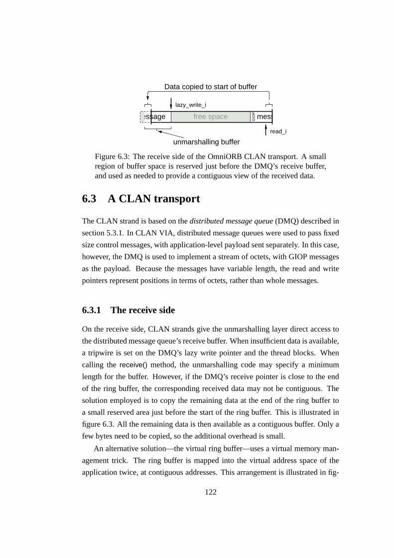
GIO
P
lazy_write_i
read_i
Data copied to start of buffer
unmarshalling buffer
free space messagemessage
Figure 6.3: The receive side of the OmniORB CLAN transport. A smallregion of buffer space is reserved just before the DMQ’s receive buffer,and used as needed to provide a contiguous view of the received data.
6.3 A CLAN transport
The CLAN strand is based on the distributed message queue (DMQ) described in
section 5.3.1. In CLAN VIA, distributed message queues were used to pass fixed
size control messages, with application-level payload sent separately. In this case,
however, the DMQ is used to implement a stream of octets, with GIOP messages
as the payload. Because the messages have variable length, the read and write
pointers represent positions in terms of octets, rather than whole messages.
6.3.1 The receive side
On the receive side, CLAN strands give the unmarshalling layer direct access to
the distributed message queue’s receive buffer. When insufficient data is available,
a tripwire is set on the DMQ’s lazy write pointer and the thread blocks. When
calling the receive() method, the unmarshalling code may specify a minimum
length for the buffer. However, if the DMQ’s receive pointer is close to the end
of the ring buffer, the corresponding received data may not be contiguous. The
solution employed is to copy the remaining data at the end of the ring buffer to
a small reserved area just before the start of the ring buffer. This is illustrated in
figure 6.3. All the remaining data is then available as a contiguous buffer. Only a
few bytes need to be copied, so the additional overhead is small.
An alternative solution—the virtual ring buffer—uses a virtual memory man-
agement trick. The ring buffer is mapped into the virtual address space of the
application twice, at contiguous addresses. This arrangement is illustrated in fig-
122

read_i (6)write_i (2)
ring buffer inphysical RAM
virtualmemorymapping
valid data
Figure 6.4: A virtual ring buffer provides a contiguous view of any regionof the buffer.
ure 6.4. Any region of the the buffer that is contiguous in ring-buffer-space is also
contiguous in the virtual address space of the application. This technique has a
number of disadvantages though:
1. It can only be used on architectures that do not exhibit aliasing in the cache.
2. The additional virtual address space consumed reduces the hit rate of the
TLB.
3. The ring buffer must be aligned on a page boundary, and its size must be a
multiple of the page size.
The third problem is particularly onerous for a CLAN distributed message
queue, since it means that the read and write pointers must be placed in a separate
pinned buffer. Although less elegant, copying a few bytes to the start of the buffer
is probably a superior solution. The virtual ring buffer is more appropriate when
the upper layer requires a contiguous view of whole messages.
6.3.2 The transmit side
The strand allocates a transmit buffer in pinned memory so that it can be used as
an RDMA source buffer. Double buffering is used in order to overlap marshalling
and data transfer: half of the buffer is passed to the marshalling layer to fill, while
the other half is transmitted by DMA. The reserve() method initiates the transfer
of data from the buffer that has just been filled, and returns the other. It may have
123

outgoing apertureat sender
ring bufferat receiver
read_i
GIO
P
lazy_read_i
lazy_write_i
write_i
unavailable
unmarshalling buffer
free space
marshalling buffer
messagefree
Figure 6.5: A CLAN strand using zero-copy marshalling
to block if a DMA transfer is in progress. The direct send() method simply copies
the supplied data into the transmit buffer, flushing it to the network as necessary.
Transfers from the transmit buffer to the receive buffer are made using DMA,
or PIO for segments that are small. Note that a transfer may be split into two when
the DMQ’s write pointer is close to the end of the ring buffer. Thus PIO is used
even when messages are large. As for CLAN VIA (section 5.3.3), proper ordering
between transfer of the payload and update of the DMQ’s write pointer must be
ensured. The strand keeps note of whether any DMA transfers are in progress,
checking if necessary with rdma test(). If there are, the write pointer is updated
using an immediate DMA request. Otherwise the write pointer is updated by PIO.
Zero-copy strands
A second version of the strand interface was implemented using zero-copy mar-
shalling. The receive side is as described in section 6.3.1. On the transmit side,
the marshalling layer is given a pointer into the outgoing aperture that maps onto
the DMQ’s receive buffer. This is illustrated in figure 6.5. GIOP messages are
marshalled directly into the receive buffer. The implementation of reserve() sim-
ply updates the DMQ’s write pointer and returns a pointer to the next region of
free space; waiting if necessary. If the DMQ’s write pointer is too close to the
end of the ring buffer to provide a sufficiently large contiguous buffer, a small
auxiliary buffer in local memory is used instead.
124

6.3.3 Buffer size and spinning
It is well known that for a system with end-to-end flow control, the amount of
buffer space required at the receiver is proportional to the product of the round-
trip delay and bandwidth. However, the latency for this calculation depends not
only on the raw latency of the network, but also on how long it takes the receiver
to acknowledge received data, and how long it takes the sender to repond to ac-
knowledgements. In other words, it depends on how tightly coupled the sender
and receiver are. If either is not scheduled when a message arrives, the delay can
be large.
The implication is that in order to stream data at high bandwidth, the receive
buffer must be large; or the receiver and sender must be tightly coupled. The most
appropriate choice will depend on the application and environment, and so should
be configurable. To keep a sender and receiver tightly coupled, CLAN strands
can be configured to spin when waiting for incoming data or acknowledgements.2
When a timeout expires, the strand reverts to blocking in order to limit the over-
head due to spinning. The spin-then-block strategy has been shown to provide
good performance in a wide variety of circumstances [Damianakis et al., 1997,
Thekkath and Levy, 1993].
Another time when it may be appropriate to spin is when an incoming mes-
sage is expected soon; for example, on the client side, when waiting for the reply
to a request that is expected to have low latency. How long this will be is applica-
tion specific, and will differ for the client and server ends of the connection. The
CLAN transport can therefore be configured with separate timeouts for transmit
and receive, and for the client and server side. The GIOP layer sets a flag in the
strand to indicate whether it is on the client or server side, so it can choose the ap-
propriate timeout. Spinning on the server side is discussed further in section 6.5.1.
An issue closely related to buffer size is the time at which the DMQ’s lazy
read and write pointers should be updated. When streaming large amounts of
data, it is desirable for marshalling at the sender and unmarshalling at the receiver
to proceed in parallel [Clark and Tennenhouse, 1990]. To achieve this, the sender
2In this context “acknowledgements” means updates to the DMQ’s lazy read pointer, whichfree up space in the receive buffer.
125

must not fill the receive buffer before updating the write pointer, since it might
then be stalled while it waits for free space. Similarly, the receiver should not
consume all the data in the buffer before updating the lazy read pointer. The
best parallelism is achieved by sending and acknowledging many small chunks of
data, but this is inefficient—especially with the poor performance of the prototype
CLAN RDMA engine.
The decision as to how often the lazy read and write pointers should be up-
dated is controlled by a pair of tunable parameters: the transmit and receive
chunk size. By experimentation, it was found that setting these at half the buffer
size gave good results. With a more efficient RDMA implementation, smaller
chunk sizes might be appropriate, and would potentially deliver lower latency.
These parameters limit the size of the buffer that the strand makes available to the
(un)marshalling layer. This forces the marshalling layer to invoke the transport
layer at the right time, so it can transmit marshalled data or acknowledge received
data.
Note that it is the send and receive chunk size, together with the raw latency
and bandwidth of the network, that determine the appropriate spin timeout for
streaming bulk data.
6.3.4 Alignment
The GIOP protocol ensures that primitive datatypes are aligned on their natural
boundaries with respect to the start of messages. This property is critical to the
zero-copy strand, where an unaligned store could cause a cross-network read.
However, messages themselves are not aligned with respect to one another. This
causes problems for the IIOP transport (as described below), but is much worse
for the CLAN transport, where consecutive messages are necessarily placed in the
same buffer.
The solution employed was to modify the protocol slightly for the CLAN
transport. Padding is added at the end of messages to ensure that all messages
are properly aligned.
The lack of alignment between messages can also be a problem for imple-
mentations of the IIOP transport. Because TCP/IP has no knowledge of GIOP
126

0
100
200
300
400
500
600
700
800
4 16 64 256 1024 4096 16384 65536
Ban
dwid
th (
Mbi
t/s)
Payload size (octets)
Figure 6.6: Bandwidth for the CORBA IIOP transport on Gigabit Ether-net. The jagged shape of the curve is caused by the ORB having to realignmessages in the receive buffer.
framing, a GIOP message boundary may be crossed by a call to the recv system
call if more than one GIOP message has arrived at the socket. When this hap-
pens the second message may have to be moved in the buffer to realign it, adding
overhead.
This is mitigated by the fact that for ordinary CORBA requests it is rare for
multiple messages to arrive at a socket. However, it does happen when using
one-way requests (which do not have a reply), and when concurrent requests are
multiplexed onto a single connection. The effect on bandwidth is shown in fig-
ure 6.6. When the payload size is such that consecutive messages are not aligned,
the bandwidth is reduced because of the overhead incurred by realigning data.
This problem can be solved for a single copy TCP by reading the message header
and body separately. However, when using unmodified GIOP with a zero-copy
interface (such as that used by Arsenic [Pratt and Fraser, 2001]) it is not possible
to avoid having to realign data.
127

6.3.5 Connection management
It was shown in section 4.8 that the cost of allocating CLAN network resources
is high. Because OmniORB opens connections on demand, this has the effect of
significantly increasing the latency of the first request made to a remote address
space. To reduce this overhead and latency, OmniORB was modified to cache
a small number of strands. For the IIOP transport this only saves a few mem-
ory allocations, but for the CLAN and VIA transports the saving is considerable,
because the user-accessible network resources can be reused.
6.4 A VIA transport
An OmniORB transport for the VIA interface was also implemented. It serves
both to illustrate the issues that arise when using VIA in a practical application,
and to provide a comparison with the CLAN transport.
6.4.1 Data transfer and buffering
The VIA strand uses the send/receive model for communication. The octet stream
required for GIOP is implemented with a stream of VIA messages, with the reli-
able delivery option to ensure messages are not lost. Flow control is credit-based,
with credits passed in the immediate data field of the VIA descriptors. As for the
CLAN strand, a configurable spin-then-block strategy is used for synchronisation.
Each strand maintains a pool of send and receive buffers. On the send side,
the reserve() method posts the descriptor for the buffer that has just been filled,
and obtains a free buffer which is returned to the marshalling layer. The receive()
method waits for a message with payload to arrive (i.e. not just flow control cred-
its), and returns the buffer to the unmarshalling layer. It also re-posts the previous
receive buffer, and may send a flow control message.
Each GIOP message starts in a separate VIA message. This ensures that the
start of each message is aligned with respect to the receive buffers, as required
by the unmarshalling layer. The transmit side maintains alignment within GIOP
messages by ensuring that the size of each VIA message (other than the last) is a
128

multiple of the message alignment. This requires that any trailing unaligned bytes
at the end of a buffer be copied to the start of the next. Each VIA receive buffer
is therefore preceded by a small reserved area; a few bytes of data may be copied
here from the end of the previous message when the contiguous buffer requested
by the unmarshalling layer crosses a VIA message boundary.
6.4.2 Flow control
When posting a receive descriptor, the strand has to decide whether it should
send a credit message to the other side, or accumulate the credit and send it in
a later message. If a GIOP message is to be transmitted soon, it makes sense to
accumulate credit and send it with the payload. Unfortunately, the strand has no
way to know whether this is the case.
To address this, the VIA strand will accumulate a configurable number of
credits on the receive side before sending a credit message. This reduces the
number of messages that only contain credit. In the default configuration, four
receive buffers are used, and the receiver will buffer one credit. When messages
each fit in a single buffer and the traffic pattern is request-response, no credit-only
messages are needed. This is a common scenario in CORBA applications.
It was noted in section 5.1.1 that an endpoint must not use its last credit, un-
less it can send credit with that message, or else the connection might become
deadlocked. In OmniORB, a strand is used by a single thread for the duration
of a request, so the traffic pattern is either request-response (for normal requests)
or unidirectional (for one-way requests). Concurrent bidirectional traffic cannot
happen. When the GIOP message size approaches or exceeds the total amount of
receive buffer space, the strand is therefore unlikely to have accumulated credit to
send when it reaches its last credit. Thus the receiver is stalled, even though it has
one credit left. The receive window is effectively reduced by one buffer.
6.4.3 Comparison with CLAN
The VIA interface is at a higher level than CLAN, and VIA’s ordered stream
of datagrams is conceptually closer to the strand interface than CLAN’s asyn-
chronous shared memory. The implementation of the VIA strand follows in an
129

obvious way from the VIA interface. However, when compared with CLAN, the
VIA strand has a number of disadvantages, as follows:
Flow control overhead
Flow control adds significant overhead when credit-only messages have to be sent.
This is common when the GIOP messages are larger than a single receive buffer.
Send and receive coupling
The send and receive paths are coupled in the VIA strand. A thread that is sending
a message may also need to synchronise with incoming messages in order to get
flow control credits. A receiving thread may also need to send messages in order
to send credits.
This is not a serious problem in this version of OmniORB, since a thread has
exclusive access to a strand for the duration of a request. However, this is not the
case in the most recent version of OmniORB (version 4), in which multiple con-
current requests may be multiplexed onto a single connection. To make the strand
work properly with independent send and receive processes would require addi-
tional locking and synchronisation, which is likely to add substantial complexity
and overhead.
One possible solution is to open a separate VIA connection for each direction
of data flow. This would remove the coupling, but would potentially halve the
number of concurrent clients supported by the system, since VIA connections are
a limited resource on native implementations.
Efficiency of buffer use
The buffer space in the receiver is used less efficiently in the VIA strand. As
described above, the last credit is unlikely to be usable, as doing so may lead to
deadlock. When four buffers are used, this reduces the effective buffer space by
25%. In addition, small messages consume an entire buffer. With a ring buffer
such as the CLAN DMQ, messages only consume as much buffer space as they
need.
130

With the default settings, CLAN and VIA strands are configured with 32 KBytes
of receive buffer space. In the VIA strand this is divided into four receive buffers.
When sending messages that are 100 octets long, the receive window for CLAN
is 327 messages. For VIA it is just 3 messages.
Using a larger number of smaller buffers for VIA would increase the receive
window, but would also increase overhead when sending larger messages. The
default of four buffers was chosen because it was found that using more buffers
did not improve performance, even for small messages. This is likely to be due to
the message rate being limited by the Emulex VIA line card.
Thread safety
The VIA standard specifies that implementations may optionally provide thread
safety, and Emulex VIA is one example that does. However, it is not needed
for OmniORB’s VIA transport, since the ORB gives just one thread at a time
exclusive access to a strand. If the ORB multiplexed multiple requests over a
single strand, it would be useful to allow two threads to access a strand at once:
one to send and the other to receive. However, in that case locking would still be
required within the strand itself, due to the send/receive coupling that is enforced
by the implementation of flow control. Thus the locking within VIA is redundant
and serves only to increase overhead.
This provides evidence to support the principle (given in section 4.7) that low
level interfaces should not be concerned with providing thread safety. Rather,
they should ensure that thread safety can be done efficiently in the upper layers,
as necessary.
The problems of high flow control overhead, send/receive coupling and the
inability to effectively make use of the last flow control credit, are all due to VIA’s
lack of explicit support for flow control. They are all solved by the flow control
extensions implemented in CLAN VIA. Removing flow control considerations
from the strand would simplify its implementation and improve performance.
131

6.5 Server-side thread model
OmniORB uses a thread-per-connection model on the server side. In this model,
a new thread is spawned for each incoming connection, and dispatches all re-
quests that arrive on that connection. This avoids thread switches during request
invocations—one factor that contributes to OmniORB’s good performance—but
has the following undesirable properties:
• A thread switch necessarily occurs between requests on different connec-
tions.
• On many architectures threads are a relatively heavy-weight resource, and
limited in number. This may limit the maximum number of connections.
• On some systems the thread scheduler performs poorly when there are many
runnable threads.
• A single connection may be serviced repeatedly until its thread is desched-
uled, at the expense of all other connections. This can cause high variance
in the service time for individual clients.
The impact of these deficiencies becomes ever more noticeable as the perfor-
mance of the transport increases. A new model that addresses the above problems
was therefore sought.
The event-driven model has been shown to be efficient for other applications,
but is particularly difficult to integrate into a CORBA ORB. The ORB is archi-
tected so that the marshalling layer calls down into the transport layer when more
data or buffer space is needed. Turning this relationship inside out would lead to a
complex state machine, because the marshalling code is hierachical and recursive.
In addition, a state machine implementation would have high overhead compared
with the existing sequential marshalling code, which has been carefully inlined
for performance. Exotic programming constructs such as continuations [Haynes
et al., 1986] offer a potentially elegant and efficient solution to this problem, but
are not available in existing systems programming languages.
An alternative is for the transport layer to only handle complete GIOP mes-
sages. A single thread could then manage I/O for many connections efficiently,
132

but it would potentially require unreasonably large buffers at the transport layer.
For some transports (such as CLAN) it is not possible to dynamically increase the
amount of receive buffer space without introducing an extra copy, which would
incur unacceptable overhead.
6.5.1 The dispatcher thread model
The dispatcher thread model was designed to overcome the deficiencies of thread-
per-connection. Given the discussion above, it seems desirable to retain the exist-
ing relationship between the marshalling and transport layers. Thus once a thread
is dispatched to handle a request on a connection, it must be assumed that it may
block—either on network I/O or in the object’s implementation (of which the
ORB has no knowledge or control).
In order to prevent a thread potentially being blocked in each connection, the
ORB must avoid dispatching a thread on a connection until a message arrives.
This is achieved by the dispatcher, which keeps track of idle connections, and uses
a suitable mechanism to determine when data arrives. For CLAN connections, the
CLAN event queue is used, and for the IIOP transport, the select system call is
used. In order to increase code-reuse it is tempting to wrap the event notification
mechanism in a common interface, but this adds overhead and precludes optimi-
sations tailored to each mechanism. A separate implementation of the dispatcher
is therefore provided for each transport. A description of the CLAN dispatcher
follows.
The operation of the dispatcher is shown in figure 6.7. A pool of threads
are available to perform work, and may be idle, blocked on the work queue or
dispatching a request. When an idle thread becomes runnable, it inspects the
CLAN event queue (labelled work queue in the diagram) to find an event and the
associated strand. If a message has arrived at the strand, the same thread handles
the incoming request by calling into the GIOP dispatch routine. A lock flag on
each strand is used to prevent more than one thread from attempting to dispatch
on the same strand. To avoid a race condition, another flag is used to indicate
whether an out-of-band message event has been received for a strand that was
locked, since this indicates that the connection has been closed.
133

Idle threads
Requestarrives
At most one threadblocked on work queue
Workqueue Threads
dispatchingincomingrequests
Idle connections
Dispatch
Figure 6.7: The dispatcher thread model
It is a goal of the dispatcher to minimise thread switches, and it is therefore
desirable to only wake idle threads when there is work for them to do. The usual
solution in thread-pool implementations is for idle threads to block on the event
queue (or other I/O event mechanism). This causes at least one thread to be woken
for each event that is delivered, even though not all of these threads may be needed
to handle the events. To prevent this behaviour, the dispatcher only allows one
thread at a time to block on the event queue; all other idle threads block on a
condition variable, and are woken explicitly as they are needed.3
When a thread discovers that a strand has an incoming message, it makes a
call into the GIOP layer to handle the request. The ORB cannot know in ad-
vance whether that thread will block, and must therefore ensure that at least one
of the idle threads (if there are any) is either blocked on the event queue, or is
in a runnable state. To achieve this, the dispatcher keeps count of the number of
idle threads, and the number of runnable threads that are not currently handling a
request. A thread that is about to dispatch first wakes an idle thread—but only if
there are no runnable threads.
3Use of a mutex for this purpose was considered, but was found to suffer from the lock-swapproblem described in section 6.5.4.
134

Spinning and caching
The CLAN dispatcher may be configured so that a thread spins for a few mi-
croseconds before blocking on the event queue. Spinning works well if the num-
ber of connections is large, since the inter-arrival time for events is likely to be
small. Since only one thread is permitted to block on the event queue, only one
thread will spin. Therefore the time spent spinning does not depend on the num-
ber of connections or the number of threads. In comparison, spinning is rarely
appropriate on the server side when using the thread-per-connection model, as the
inter-arrival time will usually be at least a round-trip, and more likely longer.
In order to reduce overhead incurred by the use of tripwires, the dispatcher
keeps a list of strands that are active, and these are polled. When a thread returns
from dispatching a request, it first polls the event queue, placing any active strands
on the “active” list. The strand that was just used for a request is then placed on
the active list—after those from the event queue. If the thread is the only runnable
idle thread, it then switches to polling mode.
In polling mode, the thread polls the event queue and the strands in the active
list. When it finds a strand with received data, it dispatches that strand. If the
dispatcher’s spin timeout expires, the receive tripwire is enabled on each strand
and they are removed from the active list. The thread then blocks on the event
queue. In addition to the dispatcher’s spin timeout, there is a smaller timeout for
each strand. Together these timeouts ensure that the overhead due to spinning
does not increase beyond a fixed amount per request invocation.
6.5.2 TCP and VIA dispatchers
TCP
The TCP dispatcher is similar to the CLAN version. It uses the select system
call to determine which connections are active. Select was chosen because it is
considerably easier to use than event-based mechanisms, does not require end-
points to be registered in advance, and has been shown to be almost as efficient as
POSIX realtime signals provided as much work as possible is done for each call
[Chandra and Mosberger, 2001]. To minimise the number of calls to select the
135

results are therefore placed in a work queue, and another call is only made when
the queue is empty. Connections are removed from the select-set while being dis-
patched. However, performance will nonetheless degrade with large numbers of
idle connections.
The TCP dispatcher does not cache recently active threads, since a system call
is needed to switch between blocking and non-blocking modes. It is simpler, and
more efficient, to include the connection in the next call to select.
VIA
An implementation of the dispatcher model for VIA presents considerable diffi-
culties. The VIA mechanism for managing large numbers of connections is the
completion queue; but VIA does not allow blocking operations on connections
that are bound to a completion queue. Once bound, a connection cannot be un-
bound from a completion queue. It is therefore not possible to use a completion
queue to identify active connections, and then serve the request independently of
the completion queue.
To get around this, the strand would have to interact with the dispatcher when-
ever it needed to block waiting for received data. This would add considerable
complexity, and would increase the number of thread switches incurred, losing a
key benefit of the dispatcher model. It seems likely that a completely different
model would be more appropriate. For these reasons, an implementation of a VIA
dispatcher was not attempted.
6.5.3 Properties of the dispatcher model
The dispatcher thread model has the following desirable properties:
• In applications where the object implementation does not cause the dis-
patching thread to block, a single thread may serve many requests on many
connections without any thread switches.
Note that a thread is unlikely to block on network I/O when messages are
small enough to fit in the strand’s receive buffer. For larger messages, an
136

appropriate choice of spin timeout will prevent the thread from blocking in
most cases.
• If a thread does block when dispatching a request, then another thread will
take over to serve any connections that have work to do (unless the thread
pool is exhausted). On multi-processor systems sufficient threads will be
woken to occupy the available processors if enough work is available.
• The dispatcher minimises overhead by avoiding thread switches, and by
avoiding waking threads that may not be able to make progress. However, it
is not possible to eliminate spurious wake-ups entirely, since the dispatcher
cannot know whether network I/O will block, or what the application-level
object implementation will do.
• Requests are serviced in order of arrival, or in round-robin order when con-
nections are cached in the active list. Compared with thread-per-connection,
the variance in service time is considerably reduced and fairness is im-
proved.
Note however that the thread scheduler is beyond the control of the ORB. If
a thread that is managing a connection is descheduled, that connection will
not receive any service until the thread is rescheduled. This is no worse than
the thread-per-connection model.
6.5.4 POSIX threads
Two features of the POSIX thread specification, and the implementation used,
were found to be important in the design of the dispatcher. They are discussed
here.
Mutexes
The dispatcher model was designed to allow a single thread to dispatch many re-
quests on many connections, without switching between threads unless the thread
blocks. However, an artifact of the Linux implementation of the POSIX Threads
mutex primitive can cause a thread switch to be forced between each request.
137

The problem is that when a mutex is unlocked, and another thread is waiting
for the mutex, the mutex is automatically donated to the waiting thread. If after
unlocking the mutex the thread tries to lock it again, it will necessarily block until
the other thread has unlocked the mutex. If the threads are in a loop, locking and
unlocking the mutex on each iteration, it is likely that they will swap the mutex
each time.
This behaviour has been seen in the dispatcher. A mutex is used to protect
access to the work queue and other state, and is locked and unlocked once each
time a thread retrieves another strand to dispatch. If access to that mutex is ever
contended, the dispatcher threads involved swap ownership of the mutex each
time they return from dispatching a request. This continues until all but one are
descheduled when not holding the mutex.
This behaviour of the Linux mutex is not specified by the POSIX standard. It
was done this way because the author of the package received complaints about
his previous version: that mutex locking behaviour was not fair, because threads
did not take turns when locking a mutex. These complaints are not valid. If turn-
taking is the desired behaviour it should be coded for explicitly. Forcing threads
to take turns when locking a mutex causes unnecessary thread switches and hence
increases overhead.
Condition variables
Another feature of the Linux threads implementation was found to be very useful.
The standard specifies that the pthread cond signal() function wakes at least one
of the threads waiting on a condition variable. The Linux implementation guar-
antees that exactly one thread will be woken. This more specific semantic allows
the dispatcher to keep an accurate count of the number of runnable threads. It can
therefore make better decisions as to when to wake threads. In order to be portable
to other systems, the dispatcher supports both behaviours, selectable at compile
time.
138

Technology Latency (µs) 95th %’ile
Gigabit Ethernet 149 178Fast Ethernet 127 128Intra-machine 55.2 55.5Emulex VIA 28.3 28.8CLAN (zero-copy) 17.2 17.4CLAN (single-copy) 16.1 16.4Results from Denis et al. [2002]Fast Ethernet (P II 450 MHz) 160Myrinet-1 (P II 450 MHz) 55Myrinet-2000 (P III 1 GHz) 20
Table 6.1: CORBA round-trip latency for null requests. The results from[Denis et al., 2002] were also obtained with OmniORB.
6.6 Performance
This section evaluates the performance of OmniORB with the various modifica-
tions described in this chapter. For the VIA transport, the Emulex cLAN 1000 was
used. The experiments were performed using the Pentium III 650 MHz systems,
flowers and cisk, detailed in the appendix.
Latency
The latency for small requests was measured by repeatedly invoking a null method:
one taking no arguments and doing no work. The CORBA interface, specified in
IDL, was as follows:
interface PingVoid {
void ping_void();
};
The results are given in table 6.1. The Gigabit Ethernet line cards use interrupt
hold-off to reduce overhead, but it has the effect of increasing latency for this
experiment. The latencies for the user-level transports are almost an order of
magnitude lower than for TCP/IP over Ethernet, and considerably better than for
139

intra-machine requests.4 OmniORB is 43% faster with the CLAN single-copy
strand than with VIA. The difference in latency between CLAN and VIA under
OmniORB (12.2 µs) is larger than the difference in latency at the raw network
interface (7.9 µs). This suggests that the VIA strand implementation adds more
overhead than the CLAN strand.
Contrary to expectations, the latency (and therefore overhead) of the CLAN
zero-copy strand is higher than for the single-copy version. This is because the
single-copy strand copies the message into PCI space in a single contiguous chunk,
storing a word at a time. With the zero-copy strand, the marshalling layer gen-
erates a mix of word-sized and sub-word stores, which are less efficient on this
platform.
Table 6.1 also gives results for OmniORB over the PadicoTM framework,
taken from Denis et al. [2002]. These are the fastest results to date for a CORBA
implementation. The results are not directly comparable, since the test platforms
differ. However, the CLAN transport achieves lower latency than a Myrinet-2000
transport despite being tested on a system with a slower processor.
Bandwidth
Bandwidth was measured by streaming a large number of one-way requests to the
server. The following IDL interface was used:
interface PingSeqOctet {
oneway void recv_seqoctet(in sequence<octet> v);
};
As for all experiments in this dissertation, the payload was touched at the
application level on both the send and receive side. A total of 100 megabytes of
payload were transfered to obtain each data point. The single-copy strand was
used for CLAN, which was configured to switch from PIO to DMA for transfers
larger than 512 octets. The results are given in figure 6.8.
For small messages, CLAN outperforms Emulex VIA. CLAN is 60% faster
for 4 byte payloads, 25% faster for 64 byte payloads, and 10% faster for 128 byte
4Intra-machine requests use the TCP loopback interface.
140

0
100
200
300
400
500
600
700
800
4 16 64 256 1024 4096 16384 65536
Ban
dwid
th (
Mbi
t/s)
Payload size (octets)
VIACLAN
Figure 6.8: Bandwidth for CORBA with CLAN and VIA transports
payloads. However, the limited PIO bandwidth on this system, and the poor per-
formance of CLAN DMA limit the bandwidth for medium sized messages. The
dips in bandwidth at large message sizes for both CLAN and VIA are caused by
interaction with the receive buffer size. The dips are particularly large for CLAN,
because of the high cost of starting an extra RDMA request.
Overhead
Figure 6.9 compares the bandwidth achieved by the CLAN and VIA transports
when the receiver is loaded so that it becomes the bottleneck. This effectively
provides an indication of the relative overhead incurred on the receive side of
each transport. The work done by the receiver was to checksum the payload thirty
times.
This data can be used to calculate the difference in the per-request overhead
for the two transports. When the bandwidth is indeed limited by receive overhead,
the following hold:
141

0
100
200
300
400
4 16 64 256 1024 4096 16384
Ban
dwid
th (
Mbi
t/s)
Payload size (octets)
CLANVIA
Figure 6.9: CORBA bandwidth when the receiver is loaded
time =messagesize
bandwidth
time = overhead + messagesize ∗ k
Where time is measured for one request; overhead is the constant per-request
overhead; bandwidth is the observed bandwidth at a particular message size; and
k is a constant that represents the cost of the checksum calculation and per-octet
overheads incurred by the ORB. k is the same for CLAN and VIA,5 but is un-
known. Eliminating time, and rearranging for k gives:
k =1
bandwidth−
overhead
messagesize
We instantiate this for each of the transports, and eliminate k. BWCLAN and
5For both transports data is delivered into the unmarshalling buffer without the intervention ofthe CPU. All other per-octet operations are shared.
142

0
1
2
3
4
5
6
7
8
4 16 64 256 1024 4096 16384
Diff
eren
ce in
ove
rhea
d (m
icro
seco
nds)
Payload size (octets)
"bw/ping_bw.gn_and_clan.rxtouch30" using 1:($1*8/$3 - $1*8/$2)
Figure 6.10: CORBA receive overhead for CLAN and VIA transports.This graph is derived from figure 6.9, and gives a measure of the addi-tional per-request overhead incurred by the VIA transport, when com-pared with CLAN.
BWV IA are the bandwidth measured for CLAN and VIA respectively. OCLAN
and OV IA are the per-request overheads. Finally, rearranging gives the difference
in overhead:
1
BWCLAN
−OCLAN
size=
1
BWV IA
−OV IA
size
OV IA − OCLAN =size
BWV IA
−size
BWCLAN
The results of this calculation are shown in figure 6.10. The difference in
per-request overheads should be independent of the payload size, so the curve is
expected to be flat—where it is not indicates where the results were not limited
by receive overhead. The results appear to be receive-limited for payloads of
between 16 octets and a little below 4096 octets. From the graph, the difference in
143

per-request receive overhead for the CLAN and VIA transports is about 3 µs. This
difference is likely to be largely due to the relatively high cost of flow control over
VIA, and the redundant locking provided by Emulex VIA.
Connection management
To measure the effect of caching strands between connections, the round-trip la-
tency of the first invocation made by a client application was measured. The work
done by the ORB on the first invocation includes creating a strand in the client
and server; establishing the connection; invoking the server to check the type and
location of the target object; and finally invoking the request.
As a baseline for comparison, the time taken for a first invocation over TCP/IP
with Fast Ethernet was 762 µs (95%<821 µs). For CLAN, the result was 1,807 µs
(95%<1,839 µs). Even taking into account the high cost of allocating CLAN end-
point resources (section 4.8), this result is surprisingly high. Reusing a cached
strand in both the client and server reduced the first-request latency to 641 µs
(95%<650 µs). For the thread-per-connection model, reusing a cached thread re-
duced the latency by a further 15 µs.
Caching and reuse of strands was also implemented for the VIA transport.
However, the connection setup time for Emulex VIA is inexplicably high, at
328 ms, and this makes all other effects negligible. The reason for this high con-
nection setup latency is unknown. Emulex VIA uses a daemon process to assist
with the rendezvous between client and server, but this alone cannot account for
all of the time taken to setup a connection.
Message rate
The performance of the implementations of the dispatcher thread model was mea-
sured by using a number of clients to apply load to a server. The same server
and client applications were used as for the latency test above. It is not possible
to simulate many clients with a single application, as was done for VIA, because
CORBA requests are synchronous. Therefore only a limited number of clients
could be tested. The server ran on flowers. For CLAN, clients were placed on
cisk, cropton and rigwelter. The latter are dual-processors, and two clients were
144

0
40000
80000
120000
160000
0 2 4 6 8 10 12
Req
uest
s pe
r se
cond
Number of clients
CLANFast Ethernet
Figure 6.11: CORBA request rate vs. offered load for OmniORB withFast Ethernet and CLAN transports
placed on each. For Fast Ethernet, a number of other machines in the laboratory
were used to supply additional load.
The results are given in figure 6.11. When using Fast Ethernet, the server was
saturated with eight clients at 21,500 requests per second. This is only slightly bet-
ter than the maximum request rate that is achieved with the thread-per-connection
model. The main advantages of the dispatcher model are improved scalability and
fairness. Gigabit Ethernet would be expected to perform a little better, as this test
would benefit from interrupt hold-off as the number of clients grows.
With the CLAN transport, the ORB achieves 145,000 requests per second with
five clients, and it appears to be almost saturated. Since these are null requests, this
result provides a measure of the total overhead due to the ORB on the server side.
For OmniORB with the CLAN transport, the overhead is just 6.9 µs per request.
In practice this will be an underestimate, since it does not take into account the
effect the ORB has on cache behaviour.
145

6.7 Related work
A number of groups have analysed the performance of communications middle-
ware, and adapted implementations for high performance networks. Gokhale and
Schmidt [1996] found that existing ORBs incur high overhead due to inefficien-
cies in presentation layer formatting and demultiplexing strategy. In [1997, 1998]
they describe a number of optimisations, many of which are already used in Om-
niORB.
Bilas and Felten [1997] implemented SunRPC over the first generation SHRIMP
network, with round-trip latency of 33 µs. They also designed a new non-compatible
RPC that took full advantage of the features of the network interface to achieve
latency of just 9.5 µs. However, the ShrimpRPC facility has a considerably less
rich feature set than CORBA.
CrispORB [Yuji et al., 1999] is a CORBA ORB designed for system area
networks, and supports TCP/IP and VIA transports. The round-trip latency was
measured as 400 µs for the VIA transport, compared with 550 µs for TCP. The rel-
atively high latency for the VIA transport is in part due to their use of an emulated
VIA implementation.
Forin et al. [1999] implemented a VIA transport for Microsoft’s DCOM mid-
dleware. Using Emulex VIA line cards and 333 MHz Pentium II systems they
achieved a 72 µs round-trip latency, whilst preserving the full set of DCOM fea-
tures. Madukkarumukumana et al. [1998] improved on this with custom mar-
shalling, achieving round-trip latency of 50 µs; but at the expense of some func-
tionality.6
Pope et al. [1998] describe a transport for OmniORB over SCI, using locked
shared memory, with latency of 156 µs on Pentium Pro 200 MHz systems. The
fastest results prior to this work were obtained by Denis et al. [2002], also using
OmniORB. They achieved a round-trip latency of 20 µs using the Myrinet-2000
network and Pentium III 1 GHz systems.
6This result is extrapolated from figure 9 in Madukkarumukumana et al. [1998].
146

6.8 Summary
This chapter has presented two improvements for high performance communi-
cation middleware. Firstly, the design and implementation of a transport for the
CLAN network that delivers the lowest latency yet reported for a CORBA ORB.
This was achieved without sacrificing any of the features or changing the seman-
tics of the ORB.
The second is a thread dispatch model that improves on existing thread-pool
models by reducing the number of thread-switches. Compared with the thread-
per-connection model it improves scalability in terms of the number of connec-
tions an ORB can handle; it increases the maximum request rate when serving
multiple clients; and it reduces variance in the response time. Having a separate
dispatcher for each transport allows an efficient implementation that can take ad-
vantage of special features of the network interface. The CLAN dispatcher in
particular adds very little overhead to each request.
The difficulties encountered while implementing VIA support illustrate a num-
ber of the deficiencies in the standard that were detailed in section 5.5.1. Flow
control was identified as a major cause of overhead, and would incur even higher
overhead in an ORB that supported bidirectional traffic on connections. The in-
flexible binding between connections and the VIA completion queue precludes a
reasonable implementation of the dispatcher thread model.
Although not a panacea, CORBA is a useful tool that considerably simplifies
distributed programming. It hides details of the network and hosts, including con-
nection management and byte-order, addressing and presentation formatting, and
it provides a high-level procedural interface. The use of a user-accessible network
as a transport is totally transparent, and can be integrated into existing applications
simply by replacing dynamically-linked system libraries. This chapter has shown
that CORBA can be implemented efficiently, and it is therefore a suitable tool for
high performance distributed applications.
147

148

Chapter 7
Conclusions
This dissertation has addressed aspects of software support for distributed com-
puting using the CLAN and VIA network interfaces. This chapter summarizes the
main results and contributions, and outlines areas for further work.
The CLAN network interface has been shown to be sufficient to support effi-
cient implementations of VIA and CORBA, and has been shown qualitatively to
be more flexible and scalable than other technologies. An efficient implementation
of CORBA over CLAN has been shown to have very low overhead, and to support
user-accessible networks transparently in existing distributed applications.
7.1 Contribution
Chapter 3 presented a detailed description of the CLAN network model and the
prototype implementation developed at AT&T Laboratories–Cambridge. The low-
level performance of the prototype network was characterised, and the PIO and
DMA mechanisms for data transfer were compared. It was found that for small
messages, PIO on the transmit side offers superior latency, bandwidth and over-
head. Depending on the system, PIO on CLAN achieves almost full link band-
width with 1024 octet messages, and half link bandwidth with messages just 72 octets
long. In addition, use of PIO was shown to simplify buffer management and there-
fore reduce overhead in upper layers.
Chapter 4 described the CLAN hardware abstraction layer, which defines the
149

low-level programming interface for CLAN. It was argued that it is better to keep
features such as thread-safety out of low-level network interfaces, since they add
overhead and are often duplicated in upper layers. This required that the interface
be designed carefully. In particular it was argued that the functions of blocking and
manipulating state should be separated. A novel interface between the application
and operating system kernel was described, which uses lock-free data structures in
shared memory to reduce overhead. This mechanism was used to implement out-
of-band message queues, tripwire notifications, RDMA request queues and event
notification queues in the C-HAL. An improved event notification mechanism, the
polled event queue architecture, was proposed. It was argued that this mechanism
would have a simple implemention compared with user-accessible queues used in
other networks, and would incur only slightly higher overhead.
Chapter 5 described a novel implementation of the Virtual Interface Archi-
tecture’s API and semantics over the CLAN network. This is significant because
it demonstrated that CLAN’s send-directed shared memory model can be used
to implement a receive-directed message-based interface. The performance of
CLAN VIA and a hardware implementation were compared, and found to be simi-
lar: the hardware implementation has slightly lower overhead for most operations,
but CLAN VIA has lower latency. CLAN VIA was shown to have advantages over
the traditional implementation, including the flexibility of a software embodiment;
the use of PIO for low latency and to meet QoS requirements; and the ability to
drop messages that overrun the receiver before they are transmitted on the net-
work. It was observed that applications requiring reliable communication must
implement flow control themselves, but that this cannot be done efficiently on top
of VIA. Extensions to CLAN VIA that support flow control transparently below
the level of the VIA interface were described.
Chapter 6 addressed the goal of delivering high performance to distributed ap-
plications. An implementation of the CORBA middleware standard was adapted
to use the CLAN and VIA network interfaces. Modifications to the ORB, and
the implementations of the CLAN and VIA transports were described in detail.
The performance results presented showed that the CLAN transport exhibits very
low latency and overhead for small messages, with latency seven times lower than
Ethernet and 43% lower than VIA. The receive-side overhead for the VIA trans-
150

port was found to be substantially higher than for CLAN, in part due to the cost
of application-level flow control.
Finally, a new thread dispatch model was described and was shown to have
advantages over existing thread-pool models. In particular, it was shown that no
thread switches are incurred on the call path, and that a single thread can dispatch
many requests. With the CLAN transport, the ORB was able to handle a request
rate six times higher than with a traditional Ethernet.
7.2 Further Work
With the closure of AT&T Laboratories–Cambridge, work on the CLAN project is
continuing only at the Laboratory for Communications Engineering, which does
not have the resources to continue development of the hardware. Current work
is focusing on support for standard Internet protocols, and a scalable bridge ar-
chitecture for communicating with the outside world, and for terminating large
numbers of TCP connections.
So far, the CLAN project has demonstrated the performance potential of the
CLAN network for a range of applications. The existing prototype implementa-
tion has a number of artifacts that have been shown to limit performance. Im-
provements in the implementation, and other topics, are therefore suggested as
areas for futher study.
RDMA support
Improved support for RDMA is needed, as the current implementation incurs high
overhead and performs poorly. The best performance would be obtained with
user-accessible RDMA request queues implemented in the line card. However,
it is worth investigating whether a single hardware RDMA request queue can be
used efficiently using techniques similar to those described in chapter 4.
Event notification
An implementation of the polled event queue architecture proposed in section 4.6.2
should substantially reduce overhead, compared with the existing interrupt-driven
151

mechanism. However, it is likely to be less efficient than user-accessible event
queues implemented in the line card. The relative costs of the two models, in
terms of performance and complexity, should be explored with a prototype imple-
mentation.
Connection management
The cost of allocating CLAN resources and setting up connections was found to
be higher than expected, and there is considerable scope for improvement. A num-
ber of techniques could be applied to reduce overhead and latency. In particular, it
should be possible to redirect outgoing apertures, and with suitable hardware sup-
port this could be done at user-level. For applications that create many short-lived
connections, reducing the cost of sending and receiving out-of-band messages
would also help.
Tripwires
The tripwire is a generic mechanism for synchronising with memory events, and
is therefore potentially applicable outside of the domain of networking. One idea
is to integrate tripwires into a computer’s memory controller. Tripwires could
then be used to synchronise with arbitrary memory events, including I/O device
events and inter-process shared memory events. This might be most useful on
multi-processor systems, especially NUMA systems, on which the cost of inter-
node synchronisation is currently high. However, it is not clear that it is feasible,
or cost effective, to match tripwires at memory speeds.
Infiniband
Chapter 5 showed that the CLAN model is able to emulate the VIA interface, and
it has been argued that implementations of CLAN are simpler and more scalable
than VIA. The Infiniband architecture defined a network interface that is similar
to VIA, but it is a very large and complex specification: existing implementations
require correspondingly large amounts of silicon with embedded processors, and
are expensive. It is therefore worth investigating whether CLAN technology could
152

be adapted to meet the goals of Infiniband. If so, then CLAN might potentially
offer a simpler, cheaper, and more scalable solution.
153

154

Appendix: Experimental testbed
The experimental testbed consisted of five workstations connected by a CLAN
switch. The Linux 2.4.6 kernel was used for the Intel-based systems, and Linux
2.2.14 for the Alpha system. The workstations used were as follows:
hosts: flowers, cisk
CPU: Pentium III, 650 MHz
cache: 256 KB
memory: 256 MB SDRAM
host bridge: Intel 440 BX
line cards: CLAN Mk3
3Com 3c985 (Gigabit Ethernet)
Emulex cLAN 1000 VIA
hosts: cropton, rigwelter
CPU: Dual Pentium III, 1 GHz
cache: 256 KB
memory: 512 MB SDRAM
host bridge: ServerWorks CNB20LE
line cards: CLAN Mk3
155

host: lowenbrau
CPU: Dual Alpha EV67, 750 MHz
cache: 8 MB
memory: 1 GB SDRAM
line cards: CLAN Mk3
The Gigabit Ethernet and Emulex VIA line cards were in a back-to-back con-
figuration, since switches for these technologies were not available for these ex-
periments. The effect of this is that they show better latency than they would
in a switched topology. The bandwidth of Gigabit Ethernet was also improved
compared with a switched configuration.
The Pentium III 650 MHz systems were chosen for most of the experiments,
because they are the least powerful, and hence best illustrate the effect of overhead
on performance.
156

References
M. B. Abbot and L. L. Peterson. Increasing network throughput by integrating
protocol layers. IEEE/ACM Transactions on Networking, 1(5):600–610, Octo-
ber 1993.
R. H. Arpaci-Dusseau, A. C. Arpaci-Dusseau, D. E. Culler, J. M. Hellerstein,
and D. A. Patterson. The architectural costs of streaming I/O: A compari-
son of workstations, clusters and SMPs. In International Symposium on High-
Performance Computer Architecture (HPCA), February 1998.
G. Banga and J. Mogul. Scalable kernel performance for Internet servers under
realistic loads. In Proceedings of USENIX Technical Conference, June 1998.
G. Banga, J. Mogul, and P. Druschel. A scalable and explicit event delivery mech-
anism for UNIX. In Proceedings of USENIX Technical Conference, June 1999.
F. Berry, E. Deleganes, and A. M. Merritt. The Virtual Interface Architecture
proof-of-concept performance results. Technical report, Intel Corporation,
1998.
A. Bilas and E. Felten. Fast RPC on the SHRIMP virtual memory mapped network
interface. Journal of Parallel and Distributed Computing, Special Issue on
Workstation Clusters and Network-based Computing, February 1997.
R. J. Black. Explicit Network Scheduling. PhD thesis, University of Cambridge
Computer Laboratory, 1995.
M. Blumrich, C. Dubnicki, E. Felten, and K. Li. Protected, user-level DMA for
the SHRIMP network interface. In Proceedings of International Symposium on
High-Performance Computer Architecture, February 1996.
157

N. Boden, D. Cohen, R. Felderman, A. Kulawik, C. Seitz, J. Seizovic, and W.-
K. Su. Myrinet—a gigabit-per-second local-area network. IEEE Micro, 15(1),
1995.
P. Buonadonna. An implementation and analysis of the Virtual Interface Archi-
tecture. Master’s thesis, University of California, Berkeley, May 1999.
P. Buonadonna, A. Geweke, and D. Culler. An implementation and analysis of the
Virtual Interface Architecture. In Proceedings of SuperComputing, November
1998.
G. Buzzard, D. Jacobson, M. Mackey, S. Marovich, and J. Wilkes. An implemen-
tation of the Hamlyn sender-managed interface architecture. In Proceedings of
USENIX Symposium on Operating Systems Design and Implementation, pages
245–259, October 1996.
A. Chandra and D. Mosberger. Scalability of Linux event-dispatch mechanisms.
In Proceedings of USENIX Technical Conference, June 2001.
J. Chase, A. Gallatin, and K. Yocum. End-system optimizations for high-speed
TCP. IEEE Communications special issue on high-speed TCP, 2001.
J. S. Chase, D. C. Anderson, A. J. Gallatin, A. R. Lebeck, and K. G. Yocum.
Network I/O with Trapeze. In Hot Interconnects Symposium, August 1999.
D. D. Clark, V. Jacobson, J. Romkey, and H. Salwen. An analysis of TCP pro-
cessing overhead. IEEE Communications Magazine, 27(6):23–29, June 1989.
D. D. Clark and D. L. Tennenhouse. Architectural considerations for a new gen-
eration of protocols. In Proceedings of SIGCOMM Symposium on Communi-
cations Architectures and Protocols, pages 200–208, September 1990.
E. Cooper, P. Steenkiste, R. Sansom, and B. Zill. Protocol implementation on the
Nectar communication processor. In Proceedings of ACM SIGCOMM Sympo-
sium, September 1990.
158

CORBA Comparison. CORBA comparison project—final project report. Tech-
nical report, MLC Systeme GmbH and Distributed Systems Research Group,
Charles University, Prague, 1998.
J. Crowcroft, I. Wakeman, Z. Wang, and D. Sirovica. Layering considered harm-
ful. IEEE Network, 6(1):7–16, January 1992.
D. Culler and J. P. Singh. Parallel Computer Architecture, A Hardware/Software
Approach, chapter 10, page 818. Morgan Kaufmann, August 1998.
DAFS. Direct Access File System, version 1.0. DAFS collaborative, http://www.-
dafscollaborative.org, 2001.
S. Damianakis, Y. Chen, and E. Felten. Reducing waiting costs in user-level com-
munication. In Proceedings of International Parallel Processing Symposium,
April 1997.
B. S. Davie. The architecture and implementation of a high-speed host interface.
IEEE Journal on Selected Areas in Communications (Special Issue on High
Speed Computer/Network Interfaces), 11(2):228–239, February 1993.
G. Delp, A. Sethi, and D. Farber. An analysis of Memnet: An experiment in high-
speed shared-memory local networking. In Proceedings of ACM Symposium on
Communications Architectures and Protocols, 1988.
A. Denis, C. Perez, and T. Priol. Towards high performance CORBA and MPI
middleware for Grid computing. In Proceedings of Grid Computing, November
2001.
A. Denis, C. Perez, and T. Priol. PadicoTM: An open integration framework for
communication middleware and runtimes. In Proceedings of IEEE Interna-
tional Symposium on Cluster Computing and the Grid, May 2002.
S. DiCecco, J. Williams, B. Terrell, J. Scott, and C. Sapuntzakis. VI / TCP (Inter-
net VI). Internet-Draft draft-dicecco-vitcp-01.txt (expired), November 2000.
159

P. Druschel and G. Banga. Lazy receiver processing (LRP): A network subsystem
architecture for server systems. In Proceedings of Symposium on Operating
Systems Design and Implementation, October 1996.
P. Druschel, L. Peterson, and B. Davie. Experiences with a high-speed network
adapter: A software perspective. Computer Communications Review, 24(4):
2–13, October 1994.
C. Dubnicki, A. Bilas, Y. Chen, S. Damianakis, and K. Li. VMMC-2: Efficient
support for reliable, connection-oriented communication. In Proceedings of
Hot Interconnects V, August 1997.
A. Edwards and S. Muir. Experience implementing a high-performance TCP in
user-space. In Proceedings of ACM SIGCOMM, 1995.
Emulex cLAN. Emulex cLAN 1000. http://www.emulex.com/products/legacy/-
vi/clan1000.html, 2002.
D. Engler, M. F. Kaashoek, and J. O. Jr. Exokernel: an operating system ar-
chitecture for application-level resource management. In Proceedings of ACM
Symposium on Operating Systems Principles, December 1995.
E. Felten. The case for application-specific communication protocols. In Proceed-
ings of Intel Supercomputer Systems Division Technology Focus Conference,
pages 171–181, 1992.
E. W. Felten. Protocol Compilation: High-Performance Communication for Par-
allel Programs. PhD thesis, University of Washington Department of Computer
Science and Engineering, 1993.
M. Fillo and R. B. Gillett. Architecture and implementation of Memory Channel
2. Digital Technical Journal, 9(1), 1997.
S. Floyd, V. Jacobson, and S. McCanne. A reliable multicast framework for light-
weight sessions and application level framing. In Proceedings of ACM SIG-
COMM, September 1995.
160

A. Forin, G. Hunt, L. Li, and Y.-M. Wang. High-performance distributed objects
over system area networks. In Proceedings of USENIX Windows NT Sympo-
sium, July 1999.
A. Gokhale and D. Schmidt. Measuring the performance of communications mid-
dleware on high-speed networks. In Proceedings of ACM SIGCOMM, 1996.
A. Gokhale and D. Schmidt. Evaluating CORBA latency and scalability over
high-speed ATM networks. In Proceedings of International Conference on Dis-
tributed Computing Systems, May 1997.
A. Gokhale and D. C. Schmidt. Principles for optimizing CORBA Internet Inter-
ORB Protocol performance. In Proceedings of Hawaii International Confer-
ence on System Science, January 1998.
D. Golub, R. Dean, A. Forin, and R. Rashid. Unix as an application program. In
Proceedings of USENIX Summer Conference, pages 87–95, June 1990.
C. T. Haynes, D. P. Friedman, and M. Wand. Continuations and coroutines. Com-
puter Languages, 11(3/4):143–153, 1986.
S. Hodges, S. Pope, D. Roberts, G. Mapp, and A. Hopper. Remoting peripherals
using memory-mapped networks. Technical Report 98.7, AT&T Laboratories–
Cambridge, 1998.
M. Ibel, K. Schauser, C. Scheiman, and M. Weis. High performance cluster com-
puting using SCI. In Proceedings of Hot Interconnects V, August 1997.
IEEE. Standard for Scalable Coherent Interface. IEEE Std 1596-1992, March
1992.
Infiniband. Infiniband Architecture Specification, Volume 1.0—General Specifica-
tions. http://www.infinibandta.org, September 2000.
V. Karamcheti and A. Chien. Software overhead in messaging layers: Where
does the time go? In Proceedings of International Conference on Architectural
Support of Programming Languages and Operating Systems, October 1994.
161

K. K. Keeton, T. E. Anderson, and D. A. Patterson. LogP quantified: The case
for low-overhead local area networks. In Proceedings of Hot Interconnects III,
1995.
J. Kuskin, D. Ofelt, M. Heinrich, J. Heinlein, R. Simoni, K. Gharachorloo,
J. Chapin, D. Nakahira, J. Baxter, M. Horowitz, A. Gupta, M. Rosenblum, and
J. Hennessy. The Stanford FLASH multiprocessor. In Proceedings of Interna-
tional Symposium on Computer Architecture, pages 302–313, April 1994.
J. Larson. The HAL interconnect PCI card. In Proceedings of CANPC Workshop,
1998.
I. Leslie, D. McAuley, R. Black, T. Roscoe, P. Barham, D. Evers, R. Fairbairns,
and E. Hyden. The design and implementation of an operating system to sup-
port distributed multimedia applications. IEEE Journal on Selected Areas in
Communications, 14(7):1280–1297, September 1996.
R. Lipton and J. Sandberg. PRAM: A scalable shared memory. Technical Report
CS-TR-180-88, Princeton University, 1988.
S.-L. Lo. The implementation of a low call overhead IIOP-based object request
broker. In Proceedings of ECOOP Workshop CORBA: Implementation, Use
and Evaluation, 1997.
S.-L. Lo and S. Pope. The implementation of a high performance ORB over multi-
ple network transports. Technical Report 98.4, AT&T Laboratories–Cambridge,
1998.
M-VIA. M-VIA project. http://www.nersc.gov/research/FTG/via/, 2002.
M-VIA perf. M-VIA performance. http://www.nersc.gov/research/FTG/via/faq.-
html#q14, 2002.
R. Madukkarumukumana, H. V. Shah, and C. Pu. Harnessing user-level network-
ing architectures for distributed object computing over high-speed networks. In
Proceedings of USENIX Windows NT Symposium, August 1998.
162

C. Maeda and B. N. Bershad. Networking performance for microkernels. In
Proceedings of Workshop on Workstation Operating Systems, pages 154–159,
April 1992.
C. Maeda and B. N. Bershad. Protocol service decomposition for high-
performance networking. In Proceedings of SOSP, pages 244–255, December
1993.
E. Markatos and M. Katevenis. Telegraphos: High-performance networking for
parallel processing on workstation clusters. In Proceedings of International
Symposium on High-Performance Computer Architecture, February 1996.
E. Markatos, M. Katevenis, G. Kalokerinos, G. Maglis, G. Milolidakis, and
T. Oikonomou. Issues in the design and implementation of user-level DMA.
Technical Report 182, Institute of Computer Science, FORTH, Crete, 1997.
R. Martin, A. Vahdat, D. Culler, and T. Anderson. Effects of communication
latency, overhead, and bandwidth in a cluster architecture. In Proceedings of
International Symposium on Computer Architecture, 1997.
M. M. Michael and M. L. Scott. Simple, fast and practical non-blocking and
blocking concurrent queue algorithms. In Proceedings of Symposium on Prin-
ciples of Distributed Computing, pages 267–275, May 1996.
J. C. Mogul and A. Borg. The effect of context switches on cache performance.
In Proceedings of International Conference on Architectural Support for Pro-
gramming Languages and Operating Systems, pages 77–84, April 1991.
J. C. Mogul and K. Ramakrishnan. Eliminating receive livelock in an interrupt-
driven kernel. ACM Transactions on Computer Systems, 15(3):217–252, 1997.
J. C. Mogul, R. F. Rashid, and M. J. Accetta. The packet filter: An efficient
mechanism for user-level network code. In Proceedings of ACM Symposium on
Operating System Principles, pages 39–51, November 1987.
D. Mosberger, L. Peterson, P. Bridges, and S. O’Malley. Analysis of techniques
to improve protocol processing latency. In Proceedings of ACM SIGCOMM,
1996.
163

S. J. Muir. Piglet: An Operating System for Network Appliances. PhD thesis,
University of Pennsylvania, 2001.
OMG. The Common Object Request Broker: Architecture and Specification, ver-
sion 2.3. Object Management Group, http://www.omg.org, June 1999.
OmniORB. The OmniORB project. http://www.uk.research.att.com/omniORB/,
2000.
M. Ostrowski. A mechanism for scalable event notification and delivery in Linux.
Master’s thesis, University of Waterloo, 2000.
M. Pagels, P. Druschel, and L. Peterson. Cache and TLB effectiveness in the
processing of network data. Technical Report 93–4, Department of Computer
Science, University of Arizona, March 1993.
S. Pope, S. Hodges, G. Mapp, D. Roberts, and A. Hopper. Enhancing distributed
systems with low-latency networking. In Proceedings of Parallel and Dis-
tributed Computing and Networks, December 1998.
S. Pope and S.-L. Lo. The implementation of a native ATM transport for a high
performance ORB. Technical Report 98.5, AT&T Laboratories–Cambridge,
1998.
I. Pratt and K. Fraser. Arsenic: A user-accessible gigabit Ethernet interface. In
Proceedings of IEEE INFOCOM, April 2001.
I. A. Pratt. The User-Safe Device I/O Architecture. PhD thesis, University of
Cambridge Computer Laboratory, 1997.
N. Provos and C. Lever. Scalable network I/O in Linux. In Proceedings of
USENIX Technical Conference, June 2000.
K. Ramakrishnan. Scheduling issues for interfacing to high speed networks. In
Proceedings IEEE Global Telecommunications Conference, pages 622–626,
December 1992.
164

J. Saltzer, D. Reed, and D. Clark. End-to-end arguments in sys-
tem design. ACM Transactions on Computer Systems, 2(4):277–288,
1984. URL http://web.mit.edu/Saltzer/www/publications/
endtoend/endtoend.pdf.
C. Sapuntzakis and D. Cheriton. TCP RDMA option. Internet-Draft draft-
csapuntz-tcprdma-00.txt (expired), February 2000.
C. Sapuntzakis and A. Romanow. The case for RDMA. Internet-Draft draft-
csapuntz-caserdma-00.txt (expired), December 2000.
R. Sites. Alpha AXP architecture. Communications on the ACM, 36(2):33–44,
February 1993.
M. Swanson and L. Stoller. Low latency workstation cluster communications
using sender-based protocols. Technical Report UUCS-96-001, University of
Utah, January 1996.
D. Tennenhouse. Layered multiplexing considered harmful. In Proceedings of
International Workshop on Protocols for High Speed Networks, May 1989.
C. Thekkath, H. Levy, and E. Lazowska. Separating data and control transfer
in distributed operating systems. In Proceedings of International Conference
on Architectural Support for Programming Languages and Operating Systems,
1994.
C. A. Thekkath and H. M. Levy. Limits to low-latency communication on high-
speed networks. ACM Transactions on Computer Systems, 11(2):179–203,
1993.
C. A. Thekkath, T. D. Nguyen, E. Moy, and E. D. Lazowska. Implementing
network protocols at user level. IEEE ACM Transactions on Networking, 1(5):
554–565, 1993.
VIA. Virtual Interface Architecture Specification, version 1.0. Available from
http://www.vidf.org, December 1997.
165

VIDF. VIDF Extensions to VIPL-1.0. Available from http://www.vidf.org,
September 2001.
VIPL. Intel Virtual Interface (VI) Architecture Developer’s Guide. Available from
http://developer.intel.com/design/servers/vi/, September 1998.
T. von Eicken, A. Basu, V. Buch, and W. Vogels. U-Net: A user-level network
interface for parallel and distributed computing. In Proceedings of ACM Sym-
posium on Operating Systems Principles, December 1995.
R. W. Watson and S. A. Mamrak. Gaining efficiency in transport services by ap-
propriate design and implementation choices. ACM Transactions on Computer
Systems, 5(2):97–120, May 1987.
M. Welsh, A. Basu, and T. von Eicken. Low-latency communication over fast
Ethernet. In Proceedings of EUROPAR, August 1996.
M. Welsh, A. Basu, and T. von Eicken. Incorporating memory management into
user-level network interfaces. In Proceedings of Hot Interconnects V, August
1997.
J. Wilkes. Hamlyn—an interface for sender-based communication. Technical Re-
port HPL-OSR-92-13, Hewlett-Packard Research Laboratory, November 1992.
M. Wilkes and A. Hopper. The Collapsed LAN: a solution to a bandwidth prob-
lem? Computer Architecture News, 25(3), July 1997.
K. Yocum, D. Anderson, J. Chase, S. Gadde, A. Gallatin, and A. Lebeck. Balanc-
ing DMA latency and bandwidth in a high-speed network adapter. Technical
Report TR-1997-20, Duke University, 1997.
I. Yuji, S. Toshiaki, I. Tooru, and K. Mitsuhiro. CrispORB: High performance
CORBA for system area network. In Proceedings of IEEE International Sym-
posium on High Performance Distributed Computing, HPDC, August 1999.
166


![[slides] Parallel and Distributed Computing on Low Latency Clusters](https://img.pdfslide.net/doc/110x75/5466a74cb4af9ff5748b4830/slides-parallel-and-distributed-computing-on-low-latency-clusters.jpg)