Embed Size (px)
Citation preview

ApprovalsUL & CSA Approved for Class I Div. 1 Locations & Class IDiv. 2 Non-Incendive. UL Listed General Purpose Valves.Meets applicable CE directives. SIL 3 capable per IEC 61508 on 8314, 8316, 8551, and8553 const. Third party certification provided by EXIDA.Refer to Engineering Section for details.
42/2•3/2
4/2•5/2•5/3SERIESLow
Power
SPEC
IAL
SERV
ICE
PILO
T
115
Features• Molded one-piece solenoid with highly efficient
solenoid cartridge and 0.55 W low wattage coil• Standard ambient temperature of 149˚F (65˚C)• Optional 176˚F (80˚C) high ambient temperature version • Designed for use in automation of plant control
systems to provide:- PLC and DCS compatibility for BUS network
and traditional wiring- Reduced temperature rise- Increase battery life- Reduce wiring cost- Energy savings
• Wide selection includes 2/2 normally closed, 3/2 normally closed (including Quick Exhaust), 3/2 universal, 4/2, 5/2, and 5/3
0.55 W Low Power Solenoid ValvesAluminum, Brass, or Stainless Steel Bodies
1/4" to 1" NPT
Solenoid EnclosuresStandard: Watertight, Types 1, 2, 3, 3S, 4, and 4X.Optional: Explosionproof and Watertight, Types 3, 3S,4, 4X, 6, 6P, 7, and 9.(To order, add prefix “EF” to catalog number. Forexplosionproof with 316 Stainless Steel hub and trim, specify prefix "EV".) Surge suppression coils also available “MF” prefix.See Optional Features Section for other available options.
8314
OrderingNormal Ambient Version: EV8551H322 24VDCHigh Ambient Version: EF HT 8316H301 24VDCSurge Suppression Version: EV MF 8314H301 24VDC
% ^ )
Valve Parts in Contact with FluidsBody Aluminum Brass Stainless SteelSeals and Discs PUR, NBR, FKM, CR, as listedSleeve 304L Stainless SteelCore and Plugnut 430F Stainless SteelCore Springs 302 Stainless SteelPilot Seat Cartridge (Series 8316 & 8344 only) CARider Rings PTFESpring Retainer CA
Construction
Electrical
Description WattageMax. Ambient
Temp. T CodeInsulation
Class PrefixStandard Ambient Version .55 W 149˚F (65˚C) T6 F -High Ambient Version .70 W 176˚F (80˚C) T5 H HTSurge Suppression Version .75 W 149˚F (65˚C) T6 F MF
Description WattageVoltage
(DC)
Min.Pull In(mA)
DropOut
(mA)
Coil Resistance@68˚F (20˚C)
(ohms)
Standard Ambient Version .55W
12V 34 1.8 25524V 17 0.89 102548V 8.5 0.45 4080
125V** 3.2 0.17 27,400
High Ambient Version .70W
12V 34 1.9 20624V 17 0.98 83048V 8.5 0.52 3185
125V** 3.2 0.2 21150
Surge Suppression Version .75W
12V 34 2.2 165*24V 17 0.98 830*48V 8.5 0.52 3185*
125V** 3.2 0.2 21150*
Note: * Surge suppression contains diode bridge. ** Not for battery applications
24VDC Spare Coil P/NStandard Ambient
Temp. VersionHigh AmbientTemp. Version
General Purpose 238710-913-D TBDExplosion Proof 238714-913-D TBDExplosion Proof, Corrosion Resistant 274714-909-D TBDExplosion Proof, Surge Suppression 276006-206-D Not AvailableExplosion Proof, Corrosion Resistant, Surge Suppression 276007-206-D Not Available
Note: For 12VDC, 48VDC and 125VDC coil PN consult factory LowPowerR7

2/2•3/24/2•5/2•5/3SERIESLowPower
4
SPECIAL SERVICEPILOT
116
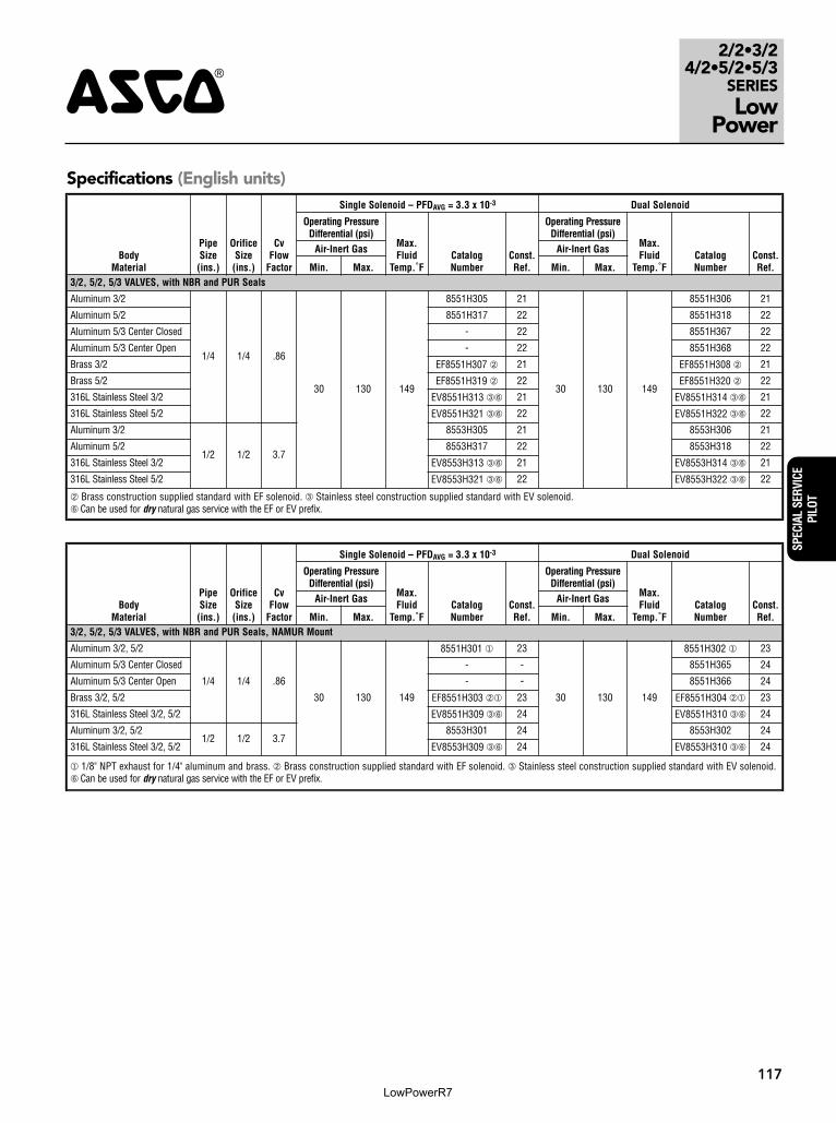
Specifications (English units)
PipeSize(ins.)
OrificeSize(ins.)
Cv FlowFactor
Operating PressureDifferential (psi)
Max.Fluid andAmbientTemp. °F
Brass Body Stainless Steel BodyAir-Inert Gas
Pressure toCylinder
Cylinder toExhaust Min. Max. Catalog Number
Const.Ref. Catalog Number
Const.Ref.
2/2 VALVES, NORMALLY CLOSED, with NBR Disc
1/4 1/16 .08 0 130 149 8262H320 18 8262H386 � 18
3/8 5/16 1.5 10 130 149 8223H323 19 - -
1/2 3/8 3.2 25 130 149 8223H303 20 8223H310 � 20
3/2 VALVES, UNIVERSAL OPERATION (Normally Closed or Normally Open) with NBR Disc – PFDAVG = 4.77 x 10⁻⁴
1/4 1/20 .06 .06 0 130/105 � 149 8314H300 1 8314H301 � 2
3/2 VALVES, NORMALLY CLOSED (Closed when de-energized) with NBR Disc or FPM, as Listed – PFDAVG = 9.30 x 10⁻⁴
1/4 5/16 1.5 1.5 � 130 149 8316H301 � 3 EV8316H381V �� 3
3/8 5/16 1.8 1.8 � 130 149 8316H302 � 3 EV8316H382V �� 3
3/8 5/8 4 4 � 130 149 8316H303 � 3A - -
1/2 5/8 4 4 � 130 149 8316H304 � 3A EV8316H384V �� 3A
3/4 11/16 5.5 5.5 10 130 149 8316J374 � 4 - -
1 1 13 13 10 130 149 8316H334 � 5 - -
3/2 VALVES, UNIVERSAL (Normally Closed or Normally Open) "Quick Exhaust" with CR Diaphragm and NBR Disc
1/4 � .06 .73 5 130 149 8317H307 � 6 8317H308 �� 7
4/2 VALVES, Brass Body with NBR Disc
PipeSize(ins.)
OrificeSize(ins.)
Cv FlowFactor
Operating PressureDifferential (psi)
Max.Fluid andAmbientTemp. °F
Single Solenoid Dual SolenoidAir-Inert GasPressure to
CylinderCylinder to
Exhaust Min. Max. Catalog NumberConst.Ref. Catalog Number
Const.Ref.
1/4 1/4 .80 1 10 130 149 8344H370 �� 9 8344H344 � 12
3/8 3/8 1.5 2.2 10 130 149 8344H372 �� 11 8344H380 � 10
1/2 3/8 1.5 2.2 10 130 149 8344H374 �� 11 8344H382 � 10
3/4 3/4 5.2 5.6 10 130 149 8344H376 �� 13 8344H354 � 14
1 3/4 5.2 5.6 10 130 149 8344H378 �� 13 8344H356 � 14
� There are two exhaust flows in the exhaust mode (pilot and main). The pilot exhaust must be connected to the main exhaust when the air or inert gas cannot be exhausted to atmosphere.� For "Quick Exhaust" valves, pressure port is 1/16", exhaust port is 1/4".� IMPORTANT: A Minimum Operating Pressure Differential must be maintained between the pressure and exhaust ports. Supply and exhaust piping must be full area, unrestricted.
ASCO flow controls and other similar components must be installed in the cylinder lines only.� Diaphragm and main disc FKM only (pilot is low-temperature NBR).� Zero minimum when valve selection gasket is in external position and proper auxiliary air pressure is applied. Minimum 15 psi Operating Pressure Differential when selection gasket
is in the internal position.� Can be used for dry natural gas service with the EF or EV prefix.� Normally closed = 130 psi. Normally open = 105 psi.
Nominal Ambient Temp. Ranges ImportantThese solenoids are intended for use on clean, dryair or inert gas filtered to 50 microns or better. To pre-vent freezing, the dew point of the media should be atleast 18˚F (-8˚C) below the minimum temperature towhich any portion of the clean air or gas system couldbe exposed. Instrument air in compliance withANSI/ISA Standard S7.3-1975 (R1981) exceeds theabove requirements and is, therefore, an acceptablemedium for these valves.
Series Body Material Normal Temperature Range High Ambient Temp. Version
8551/8553Aluminum 5°F to 149°F (-15°C to 65°C)
Low Limit is the same as NormalTemperature Ratings, but High
Limit is 175°F (80°C)
Brass / Stainless Steel
-40°F to 149°F (-40°C to 65°C)8262
Brass / Stainless Steel
8314
8317
-4°F to 149°F (-20°C to 65°C)8344*
8316
8316 (Suffix V) 32°F to 149°F (0°C to 65°C)
*Not available in stainless steel
LowPowerR7
2/2•3/24/2•5/2•5/3
SERIESLow
Power4
SPEC
IAL
SERV
ICE
PILO
T
117
BodyMaterial
PipeSize(ins.)
OrificeSize(ins.)
CvFlow
Factor
Single Solenoid – PFDAVG = 3.3 x 10⁻³ Dual Solenoid
Operating PressureDifferential (psi)
Max.Fluid
Temp.˚FCatalogNumber
Const.Ref.
Operating PressureDifferential (psi)
Max.Fluid
Temp.˚F CatalogNumber
Const.Ref.
Air-Inert Gas Air-Inert Gas
Min. Max. Min. Max.3/2, 5/2, 5/3 VALVES, with NBR and PUR Seals
Aluminum 3/2
1/4 1/4 .86
30 130 149
8551H305 21
30 130 149
8551H306 21
Aluminum 5/2 8551H317 22 8551H318 22
Aluminum 5/3 Center Closed - 22 8551H367 22
Aluminum 5/3 Center Open - 22 8551H368 22
Brass 3/2 EF8551H307 � 21 EF8551H308 � 21
Brass 5/2 EF8551H319 � 22 EF8551H320 � 22
316L Stainless Steel 3/2 EV8551H313 �� 21 EV8551H314 �� 21
316L Stainless Steel 5/2 EV8551H321 �� 22 EV8551H322 �� 22
Aluminum 3/2
1/2 1/2 3.7
8553H305 21 8553H306 21
Aluminum 5/2 8553H317 22 8553H318 22
316L Stainless Steel 3/2 EV8553H313 �� 21 EV8553H314 �� 21
316L Stainless Steel 5/2 EV8553H321 �� 22 EV8553H322 �� 22
� Brass construction supplied standard with EF solenoid. � Stainless steel construction supplied standard with EV solenoid.� Can be used for dry natural gas service with the EF or EV prefix.
Specifications (English units)
BodyMaterial
PipeSize(ins.)
OrificeSize(ins.)
CvFlow
Factor
Single Solenoid – PFDAVG = 3.3 x 10⁻³ Dual Solenoid
Operating PressureDifferential (psi)
Max.Fluid
Temp.˚FCatalogNumber
Const.Ref.
Operating PressureDifferential (psi)
Max.Fluid
Temp.˚F CatalogNumber
Const.Ref.
Air-Inert Gas Air-Inert Gas
Min. Max. Min. Max.3/2, 5/2, 5/3 VALVES, with NBR and PUR Seals, NAMUR Mount
Aluminum 3/2, 5/2
1/4 1/4 .86
30 130 149
8551H301 � 23
30 130 149
8551H302 � 23
Aluminum 5/3 Center Closed - - 8551H365 24
Aluminum 5/3 Center Open - - 8551H366 24
Brass 3/2, 5/2 EF8551H303 �� 23 EF8551H304 �� 23
316L Stainless Steel 3/2, 5/2 EV8551H309 �� 24 EV8551H310 �� 24
Aluminum 3/2, 5/21/2 1/2 3.7
8553H301 24 8553H302 24
316L Stainless Steel 3/2, 5/2 EV8553H309 �� 24 EV8553H310 �� 24
� 1/8" NPT exhaust for 1/4" aluminum and brass. � Brass construction supplied standard with EF solenoid. � Stainless steel construction supplied standard with EV solenoid.� Can be used for dry natural gas service with the EF or EV prefix.
LowPowerR7

2/2•3/24/2•5/2•5/3SERIESLowPower
4
SPECIAL SERVICEPILOT
118
Specifications (Metric units)
PipeSize(ins.)
OrificeSize(mm)
Kv FlowFactor (m3/h)
Operating PressureDifferential (bar)
Max.Fluid andAmbientTemp. °C
Brass Body Stainless Steel BodyAir-Inert Gas
Pressure toCylinder
Cylinder toExhaust Min. Max. Catalog Number
Const.Ref. Catalog Number
Const.Ref.
2/2 VALVES, NORMALLY CLOSED, with NBR Disc
1/4 2 .07 0 8.8 65 8262H320 18 8262H386 � 18
3/8 8 1.3 0.7 8.8 65 8223H323 19 - -
1/2 10 2.7 1.7 8.8 65 8223H303 20 8223H310 � 20
3/2 VALVES, UNIVERSAL OPERATION (Normally Closed or Normally Open) with NBR Disc – PFDAVG = 4.77 x 10⁻⁴
1/4 1.3 .05 .05 0 8.8/7 � 65 8314H300 1 8314H301 � 2
3/2 VALVES, NORMALLY CLOSED (Closed when de-energized) with NBR Disc or FPM, as Listed – PFDAVG = 9.30 x 10⁻⁴
1/4 8 1.3 1.3 � 8.8 65 8316H301 � 3 EV8316H381V �� 3
3/8 8 1.6 1.6 � 8.8 65 8316H302 � 3 EV8316H382V �� 3
3/8 16 3.5 3.5 � 8.8 65 8316H303 � 3A - -
1/2 16 3.5 3.5 � 8.8 65 8316H304 � 3A EV8316H384V �� 3A
3/4 17 4.7 4.7 0.7 8.8 65 8316J374 � 4 - -
1 25 11.2 11.2 0.7 8.8 65 8316H334 � 5 - -
3/2 VALVES, UNIVERSAL (Normally Closed or Normally Open) "Quick Exhaust" with CR Diaphragm and NBR Disc
1/4 � .07 .63 0.3 8.8 65 8317H307 � 6 8317H308 �� 7
4/2 VALVES, with NBR Disc and Seals
1/4 2 .07 .07 0.7 8.8 65 8345H301 �� 6 EV8345H381 ��� 8
4/2 VALVES, Brass Body with NBR Disc
PipeSize(ins.)
OrificeSize(mm)
Kv FlowFactor (m3/h)
Operating PressureDifferential (bar)
Max.Fluid andAmbientTemp. °C
Single Solenoid Dual SolenoidAir-Inert Gas
Pressure toCylinder
Cylinder toExhaust Min. Max. Catalog Number
Const.Ref. Catalog Number
Const.Ref.
1/4 6 .69 .86 0.7 8.8 65 8344H370 �� 9 8344H344 � 12
3/8 10 1.3 1.9 0.7 8.8 65 8344H372 �� 11 8344H380 � 10
1/2 10 1.3 1.9 0.7 8.8 65 8344H374 �� 11 8344H382 � 10
3/4 19 4.5 4.8 0.7 8.8 65 8344H376 �� 13 8344H354 � 14
1 19 4.5 4.8 0.7 8.8 65 8344H378 �� 13 8344H356 � 14
� There are two exhaust flows in the exhaust mode (pilot and main). The pilot exhaust must be connected to the main exhaust when the air or inert gas cannot be exhausted to atmosphere.� For "Quick Exhaust" valves, pressure port is 1/16", exhaust port is 1/4".� IMPORTANT: A Minimum Operating Pressure Differential must be maintained between the pressure and exhaust ports. Supply and exhaust piping must be full area, unrestricted.
ASCO flow controls and other similar components must be installed in the cylinder lines only.� Diaphragm and main disc FKM only (pilot is low-temperature NBR).� Zero minimum when valve selection gasket is in external position and proper auxiliary air pressure is applied. Minimum 1.0 bar Operating Pressure Differential when selection gasket
is in the internal position.� Can be used for dry natural gas service with the EF or EV prefix.� Normally closed = 8.8 bar / Normally open = 7 bar.
LowPowerR7

2/2•3/24/2•5/2•5/3
SERIESLow
Power4
SPEC
IAL
SERV
ICE
PILO
T
119
Specifications (Metric units)
BodyMaterial
PipeSize(ins.)
OrificeSize(mm)
Kv FlowFactor(m3/h)
Single Solenoid – PFDAVG = 3.3 x 10⁻³ Dual Solenoid
Operating PressureDifferential (bar)
Max.Fluid
Temp.˚CCatalogNumber
Const.Ref.
Operating PressureDifferential (bar)
Max.Fluid
Temp.˚C CatalogNumber
Const.Ref.
Air-Inert Gas Air-Inert Gas
Min. Max. Min. Max.3/2, 5/2, 5/3 VALVES, with NBR and PUR Seals
Aluminum 3/2
1/4 6 .74
2 8.8 65
8551H305 21
2 8.8 65
8551H306 21
Aluminum 5/2 8551H317 22 8551H318 22
Aluminum 5/3 Center Closed - 22 8551H367 22
Aluminum 5/3 Center Open - 22 8551H368 22
Brass 3/2 EF8551H307 � 21 EF8551H308 � 21
Brass 5/2 EF8551H319 � 22 EF8551H320 � 22
316L Stainless Steel 3/2 EV8551H313 �� 21 EV8551H314 �� 21
316L Stainless Steel 5/2 EV8551H321 �� 22 EV8551H322 �� 22
Aluminum 3/2
1/2 13 3.2
8553H305 21 8553H306 21
Aluminum 5/2 8553H317 22 8553H318 22
316L Stainless Steel 3/2 EV8553H313 �� 21 EV8553H314 �� 21
316L Stainless Steel 5/2 EV8553H321 �� 22 EV8553H322 �� 22
� Brass construction supplied standard with EF solenoid. � Stainless steel construction supplied standard with EV solenoid.� Can be used for dry natural gas service with the EF or EV prefix.
BodyMaterial
PipeSize(ins.)
OrificeSize(mm)
Kv FlowFactor(m3/h)
Single Solenoid – PFDAVG = 3.3 x 10⁻³ Dual Solenoid
Operating PressureDifferential (bar)
Max.Fluid
Temp.˚CCatalogNumber
Const.Ref.
Operating PressureDifferential (bar)
Max.Fluid
Temp.˚C CatalogNumber
Const.Ref.
Air-Inert Gas Air-Inert Gas
Min. Max. Min. Max.3/2, 5/2, 5/3 VALVES, with NBR and PUR Seals, NAMUR Mount
Aluminum 3/2, 5/2
1/4 � 6 .74
2 8.8 65
8551H301 � 23
2 8.8 65
8551H302 � 23
Aluminum 5/3 Center Closed - - 8551H365 24
Aluminum 5/3 Center Open - - 8551H366 24
Brass 3/2, 5/2 EF8551H303 �� 23 EF8551H304 �� 23
316L Stainless Steel 3/2, 5/2 EV8551H309 �� 24 EV8551H310 �� 24
Aluminum 3/2, 5/21/2 13 3.2
8553H301 24 8553H302 24
316L Stainless Steel 3/2, 5/2 EV8553H309 �� 24 EV8553H310 �� 24
� 1/8" NPT exhaust for 1/4" aluminum and brass. � Brass construction supplied standard with EF solenoid. � Stainless steel construction supplied standard with EV solenoid.� Can be used for dry natural gas service with the EF or EV prefix.
LowPowerR7

2/2•3/24/2•5/2•5/3SERIESLowPower
4
SPECIAL SERVICEPILOT
120
Dimensions: inches (mm)
.45[11.43] 2.0
[49.56]
1.59[40.5]
1.19[30.1]
.9[22.2]
.9[22.2]
1/2 NPT
1.7[42.27]
3.17[80.42]
M5 THREADn3.4 MIN FULL THREAD DEPTH.45 `0.5 MIN. TAP DRLL DEPTH
2 PLACES
Const. Ref. 1, 2
Const. Ref. 3
Const. Ref. 3A
LowPowerR7

2/2•3/24/2•5/2•5/3
SERIESLow
Power4
SPEC
IAL
SERV
ICE
PILO
T
121
Const. Ref. 18
Const. Ref. 4, 5
Dimensions: inches (mm)
Const. Ref. 6. 7
Const. Ref. 8
Const.Ref. A B C H K L M N P R W
4ins. 1.61 1.41 1.66 6.78 3.68 3.38 2.16 .53 5.09 .50 3.31mm 41 36 42 172 93 86 55 13 129 13 84
5ins. X 1.78 X 7.40 3.93 4.44 2.81 .87 5.34 1.74 5.31mm X 45 X 188 100 113 71 22 136 44 135
LowPowerR7

2/2•3/24/2•5/2•5/3SERIESLowPower
Dimensions: inches (mm)
Const. Ref. 20Const. Ref. 19
Const. Ref. 9, 10, 11, 12, 13, 14
Const.Ref. Dia “D” E F G H J K L N P W X Y Z
ExhaustPipe Size
9ins. Ø .28 .56 2.41 1.88 4.67 1.03 2.30 3.12 .72 3.72 4.75 1.41 1.56 .81
3/8mm 7 14 61 48 119 26 58 79 18 95 121 36 40 21
10ins. Ø .34 .76 3.12 2.62 4.89 1.50 2.11 3.18 .83 3.77 6.06 1.86 1.89 .83
1/2mm 9 16 79 67 118 38 70 81 21 90 154 48 49 21
11ins. Ø .34 .76 3.12 2.62 4.65 1.50 2.11 3.18 .83 3.53 6.06 1.86 1.89 .83
1/2mm 9 35 97 99 138 53 54 116 40 99 210 54 67 30
12ins. Ø .28 .56 2.41 1.88 5.06 1.03 2.71 3.12 .72 4.12 4.81 1.41 1.56 .81
3/8mm 7 14 61 48 129 26 69 79 18 105 122 36 40 21
13ins. Ø .34 .78 3.12 2.62 5.27 1.50 2.49 3.19 .84 4.16 6.06 1.88 1.91 .84
1mm 9 16 79 67 134 38 63 81 21 106 154 48 49 21
14ins. Ø .34 1.38 3.81 3.88 6.09 2.09 3.18 4.56 1.56 4.59 8.25 2.12 2.62 1.16
1mm 9 35 97 99 155 53 81 116 40 117 210 54 67 30
SPECIAL SERVICEPILOT
4
122 LowPowerR7

2/2•3/24/2•5/2•5/3
SERIESLow
Power4
SPEC
IAL
SERV
ICE
PILO
T
Optional Manual OperatorsAdd Suffix Description
MO1
20
Push and turn to lock with flathead screwdriver slot
MI1
20
Momentary push in with flathead screwdriver slot
MH
1
20Momentary push in by hand
MS
1
20Push and turn to lock by hand
Series 8551 8553NPT 1/4 1/2L1 � 5.12 (132) 6.00 (153)L2 � 6.73 (171) 7.80 (198)H2 4.38 (111) 4.77 (121)H1 1.10 (28) 1.58 (40)W 1.77 (45) 2.85 (72)
� Manual override option MH adds .250" (6.4), MS option adds .468" (11.9) to each solenoid endcap.
Optional Manual OperatorsAdd Suffix Description
MO1
20
Push and turn to lock with flathead screwdriver slot
MI1
20
Momentary push in with flathead screwdriver slot
MH
1
20Momentary push in by hand
MS
1
20Push and turn to lock by hand
� Manual override option MH adds .250" (6.4), MS option adds .468" (11.9) to each solenoid endcap.
Series 8551 8553NPT 1/4 1/2L1 � 5.63 (144) 7.06 (180)L2 � 7.20 (183) 8.86 (225)H2 4.38 (111) 4.77 (121)H1 1.10 (28) 1.58 (40)W 1.77 (45) 2.85 (72)
123
Dimensions: inches (mm)
Const. Ref. 22
Const. Ref. 21
2.03 [52]
3.02 [77]
H2
H1
L1
L2
3 1
1
W1/8 NPT AUX. PRESSURE PORT
H2
H1
L1
L2
5 1 3
W
2.03 [52]
3.02 [77]
1/8 NPT AUX. PRESSURE PORT
LowPowerR7
2/2•3/24/2•5/2•5/3SERIESLowPower
4
SPECIAL SERVICEPILOT
124
Dimensions: inches (mm)
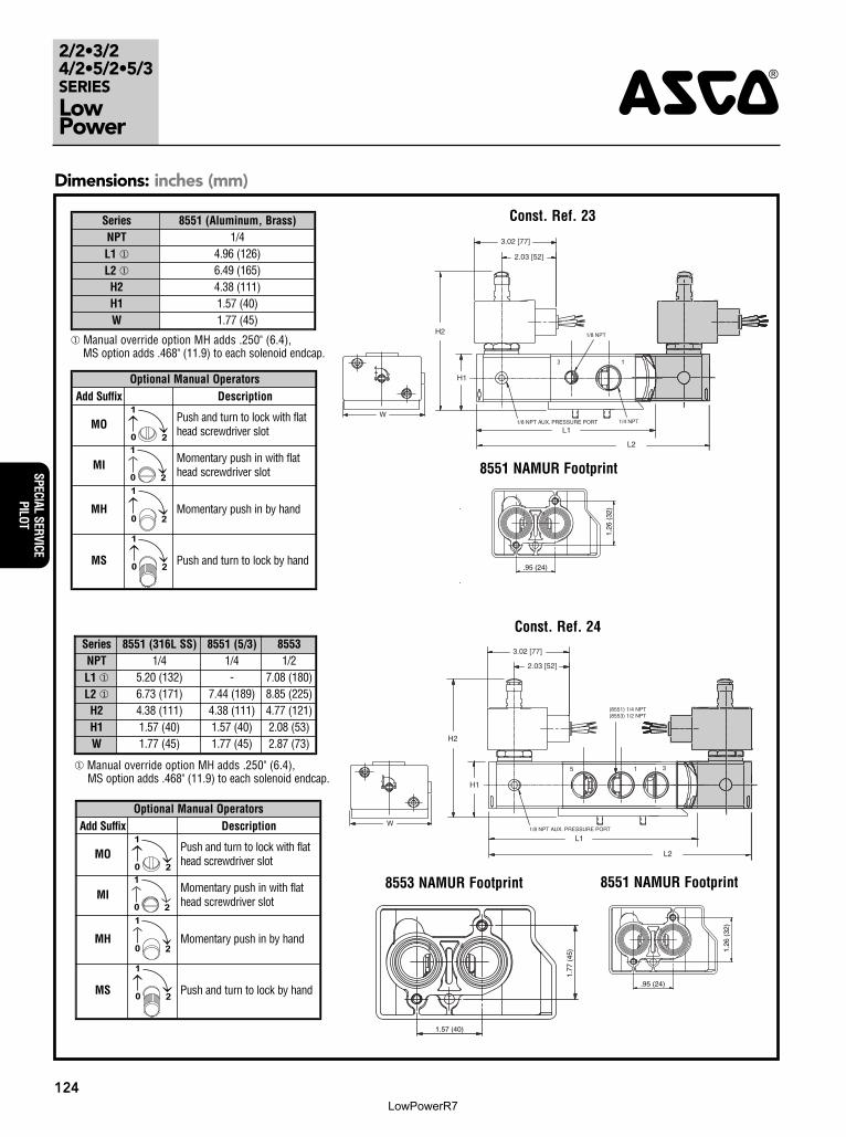
Optional Manual OperatorsAdd Suffix Description
MO1
20
Push and turn to lock with flathead screwdriver slot
MI1
20
Momentary push in with flathead screwdriver slot
MH
1
20Momentary push in by hand
MS
1
20Push and turn to lock by hand
Series 8551 (Aluminum, Brass)NPT 1/4L1 � 4.96 (126)L2 � 6.49 (165)H2 4.38 (111)H1 1.57 (40)W 1.77 (45)
� Manual override option MH adds .250" (6.4), MS option adds .468" (11.9) to each solenoid endcap.
Optional Manual OperatorsAdd Suffix Description
MO1
20
Push and turn to lock with flathead screwdriver slot
MI1
20
Momentary push in with flathead screwdriver slot
MH
1
20Momentary push in by hand
MS
1
20Push and turn to lock by hand
Series 8551 (316L SS) 8551 (5/3) 8553NPT 1/4 1/4 1/2L1 � 5.20 (132) - 7.08 (180)L2 � 6.73 (171) 7.44 (189) 8.85 (225)H2 4.38 (111) 4.38 (111) 4.77 (121)H1 1.57 (40) 1.57 (40) 2.08 (53)W 1.77 (45) 1.77 (45) 2.87 (73)
� Manual override option MH adds .250" (6.4), MS option adds .468" (11.9) to each solenoid endcap.
8553 NAMUR Footprint 8551 NAMUR Footprint
8551 NAMUR Footprint
42
.95 (24)
1.26
(32
)
42
1.57 (40)
1.77
(45
)
42
.95 (24)
1.26
(32
)
2.03 [52]
3.02 [77]
H2
H1
L1
L2
3 1
W1/8 NPT AUX. PRESSURE PORT 1/4 NPT
1/8 NPT
H2
H1
L1
L2
5 1 3
W
2.03 [52]
3.02 [77]
1/8 NPT AUX. PRESSURE PORT
(8551) 1/4 NPT(8553) 1/2 NPT
Const. Ref. 24
Const. Ref. 23
LowPowerR7