Embed Size (px)
Citation preview
Technical Physics, Vol. 49, No. 5, 2004, pp. 565–571. Translated from Zhurnal Tekhnichesko
œ
Fiziki, Vol. 74, No. 5, 2004, pp. 44–49.Original Russian Text Copyright © 2004 by Vavilin, Rukhadze, Ri, Plaksin.
GAS DISCHARGES,PLASMA
Low-Power RF Plasma Sources for Technological Applications: I. Plasma Sources without a Magnetic Field
K. V. Vavilin*, A. A. Rukhadze**, M. Kh. Ri*, and V. Yu. Plaksin** Moscow State University, Vorob’evy Gory, Moscow, 119899 Russia
** Prokhorov Institute of General Physics, Russian Academy of Sciences, ul. Vavilova 38, Moscow, 119991 RussiaReceived September 10, 2003
Abstract—A general analytical theory is developed and numerical simulations are carried out of cylindricalplasma sources operating at an industrial frequency of f = 13.56 MHz (ω = 8.52 × 10⁷ s–1). Purely inductivesurface exciters of electromagnetic fields (exciting antennas) are considered; the exciters are positioned eitherat the side surface of the cylinder or at one of its end surfaces. In the latter case, the plasma flows out ofthe source through the opposite end of the cylinder. A study is made of both elongated systems in which thelength L of the cylinder exceeds its diameter 2R and planar disk-shaped systems with L < 2R. The electromag-netic fields excited by the antenna in the plasma of the source are determined, and the equivalent plasma resis-tance, as well as the equivalent rf power deposited in the plasma, is calculated. © 2004 MAIK “Nauka/Interpe-riodica”.
1. INTRODUCTION: DESIGN OF THE SOURCES AND MAIN PLASMA PARAMETERS
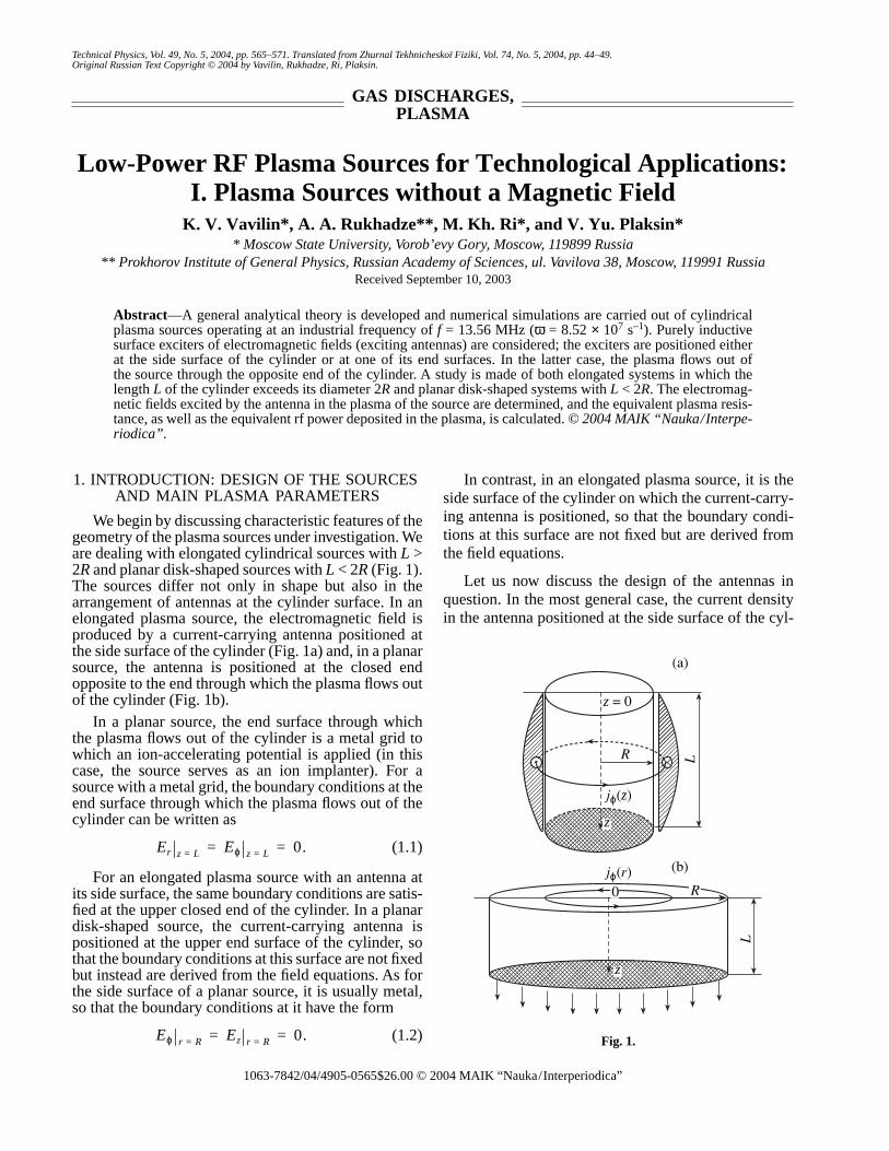
We begin by discussing characteristic features of thegeometry of the plasma sources under investigation. Weare dealing with elongated cylindrical sources with L >2R and planar disk-shaped sources with L < 2R (Fig. 1).The sources differ not only in shape but also in thearrangement of antennas at the cylinder surface. In anelongated plasma source, the electromagnetic field isproduced by a current-carrying antenna positioned atthe side surface of the cylinder (Fig. 1a) and, in a planarsource, the antenna is positioned at the closed endopposite to the end through which the plasma flows outof the cylinder (Fig. 1b).
In a planar source, the end surface through whichthe plasma flows out of the cylinder is a metal grid towhich an ion-accelerating potential is applied (in thiscase, the source serves as an ion implanter). For asource with a metal grid, the boundary conditions at theend surface through which the plasma flows out of thecylinder can be written as
(1.1)
For an elongated plasma source with an antenna atits side surface, the same boundary conditions are satis-fied at the upper closed end of the cylinder. In a planardisk-shaped source, the current-carrying antenna ispositioned at the upper end surface of the cylinder, sothat the boundary conditions at this surface are not fixedbut instead are derived from the field equations. As forthe side surface of a planar source, it is usually metal,so that the boundary conditions at it have the form
(1.2)
Er z L= Eϕ z L= 0.= =
Eϕ r R= Ez r R= 0.= =
1063-7842/04/4905- $26.00 © 20565
In contrast, in an elongated plasma source, it is theside surface of the cylinder on which the current-carry-ing antenna is positioned, so that the boundary condi-tions at this surface are not fixed but are derived fromthe field equations.
Let us now discuss the design of the antennas inquestion. In the most general case, the current densityin the antenna positioned at the side surface of the cyl-
(a)
(b)
z = 0
R L
z
jϕ(z)
jϕ(r)R
L
z
0
Fig. 1.
004 MAIK “Nauka/Interperiodica”
566
VAVILIN
et al
.
inder can be represented as
(1.3)
where F1(ϕ, z) is an arbitrary function that can beexpanded in a Fourier series.
Below, the problem of investigating the plasmasource will be solved for an individual term of the Fou-rier series under the assumption that the antenna currentis azimuthally symmetric and the arbitrary function hasthe form
where I0 is the net antenna current and iϕ is a unit vectorin the azimuthal direction.
The current density in the antenna positioned at theend surface of the cylinder is represented in an analo-gous form. In the general case, the antenna current den-sity can be written as
(1.4)
In what follows, however, we will be interested in anazimuthally symmetric antenna current and will use thefunction
where I0 is the net antenna current, J1(x) is a first-orderBessel function, and µ ≈ 3.8 is the first root of theBessel function (J1(µ) = 0).
Let us now discuss the mechanisms by which the rfenergy is dissipated within the plasma of the source. Weare interested in a plasma with the following parame-ters: the neutral gas pressure is p0 < 10–3 torr (whichcorresponds to a neutral density of n0 ≈ 3 × 1013 cm–3)and the electron density is ne ≈ 1010–1011 cm–3. In sucha plasma, two dissipation mechanisms—collisionlessdissipation due to Cherenkov absorption and collisionalfield dissipation due to collisions of plasma electronswith plasma ions and with gas atoms and molecules—play an equally important role. In this case, the collisionfrequency can be represented as
(1.5)
where Te is the electron temperature in eV, p0 is the gaspressure in torr, and n0 is the ion density in cm–3. Notethat, in source plasmas, the electron temperature satis-fies the condition Te @ Ti ~ T0, where Ti is the ion tem-perature and T0 is the gas temperature (which is usuallyon the order of room temperature). Such plasma param-eters are determined by the large difference between themass of the electrons and the masses of heavy particles(ions and neutrals), in which case the collisional energyexchange between electrons and heavy particles is hin-
j r( ) δ r R–( )F1 ϕ z,( ),=
F1 ϕ z,( ) iϕ I0πzL-----,sin∼
j r( ) δ z( )F2 ϕ r,( ).=
F2 ϕ r,( ) iϕ I0J1µrR------
,∼
νe νen νei+ Te eV( )6 109 p0
10 4– ne
Te eV( )3/2----------------------,+×≈=
dered. For typical experimental conditions such thatTe ~ 5 eV and VTe ≈ 9 × 107 cm/s, and for ne < 1012 cm–3
and p0 < 10–3 torr, we have νe ~ 1.5 × 10⁷ s–1. Underthese conditions, the collisional dissipation of the rfenergy in plasma can be assumed to be weak becauseω = 8.5 × 10⁷ s–1 @ νe ~ 1.5 × 10⁷ s−1.
For the above plasma parameters, the mean free pathof an electron is on the order of l = VTe/νe ≈ 10 cm. Itcan be shown that the maximum efficiency of a plasmasource operating in a steady mode is achieved when thelength of the system does not exceed the electron meanfree path l, i.e., when
(1.6)
In what follows, this condition will be assumed to bealways satisfied.
The second, purely collisionless, dissipation mech-anism is governed by both the electron thermal motionand the geometric dimensions of the system. The con-tribution of this mechanism to the collision frequency isdetermined by the parameters kVTe ≈ πVTe/L and πVTe/R.The characteristic geometric dimensions of an elon-gated rf plasma source are L ≥ 10 cm and R ≤ 10 cm,while those of a planar source are L ≤ 10 cm and R ≥10 cm. As a result, we have kVTe ≈ 1–2 × 10⁷ s–1 ! ω, sothat the collisionless rf energy dissipation in the sourceis also weak. On the other hand, we have kVTe ≈ νe,which indicates that the collisionless dissipation iscomparable in importance to the collisional dissipation.That is why we will assume that both of the dissipationmechanisms operate simultaneously in the plasma.
The external magnetic field is longitudinal only,B0 || OZ. It has an important effect on the operatingmodes of the plasma sources. It is easy to show that,even for relatively weak external magnetic fields (5 ≤B0 ≤ 500 G), the following conditions hold:
(1.7)
These conditions will be assumed to be satisfied forplasma sources with an external magnetic field. Suchsources are the subject of parts II and III of the presentpaper. The objective of part I is to investigate plasmasources without a magnetic field (B0 = 0).
Finally, let us discuss the question of what is the rfpower that is deposited in the plasma of the source (i.e.,the power that ensures the operation of the source). Thispower depends essentially on the mass of an ion, M,which is assumed to be about 30–40 masses of a hydro-gen atom (M ~ 2 × 10–24 g). In this case, the plasmaflows out of the source with a velocity on the order ofthe ion acoustic speed (provided that the plasma ions
L le≤ 10 cm.≈
ωLe 1010 s 1– @ Ωe≥
= eB0
mc-------- 109 s 1–
@ ω 8.5 107× s 1– .≈≤
TECHNICAL PHYSICS Vol. 49 No. 5 2004
LOW-POWER RF PLASMA SOURCES FOR TECHNOLOGICAL APPLICATIONS 567
are not accelerated by any additional means),
For an ion density of ni ≈ 1012 cm–3, this formulayields the following estimate for the density of the ioncurrent from the source:
(1.8)
Since the plasma thermal energy is determined bythe electron temperature Te, which is about 5 eV, thedensity of the power flux from the source through a unitarea of the end surface of the cylinder is equal to
(1.9)
so that the net power flux from the source is
(1.10)
where the total area of the end surface of the cylinder,S, is expressed in cm2.
For an elongated system with R < 10 cm, we have3W < 150 W, whereas for a planar disk-shaped sourcewith R > 10 cm, the net power flux is 3W > 150 W.
It is also an easy matter to estimate the total powerthat is deposited in the discharge plasma in order tomaintain the steady-state operation of the source. To dothis, we must take into account not only the electronplasma heating to a temperature of Te ~ 5 eV but alsothe power lost to ionize neutral gas atoms and, in theabsence of magnetic field, the power carried to the sidesurface of the cylinder by the plasma. Unfortunately,the amount of power expended on ionizing the gasatoms in an rf discharge is very high (most of the fieldenergy is spent on the excitation of atoms, which is fol-lowed by the emission of optical photons from theexcited atomic states). As a consequence, the net rfpower absorbed by the plasma in the source is higherthan the net power flowing out of the source by one oreven two orders of magnitude, i.e., 3W ≈ 103–104 W.
To conclude this section, we will say a few words onadditional power losses in the acceleration of ions inion implanters. The problem concerning the power ofan ion accelerator is a separate issue and is not relatedto the problem of the rf power fed into a plasma source.In what follows, we will not deal with the accelerator-related problem, because it goes beyond the scope ofthis paper, the primary goal of which is to investigatethe steady-state operation of rf plasma sources.
v s
Ts
M----- 3 105× cm/s.≈=
j eniv s 5 10 10–×( ) 1012( ) 3 105×( ) 1
3 109×-----------------
A
cm2---------≈=
≈ 5 10 2–× A
cm2---------.
PW niv sTe≈ niv sMv s2+ 2niv sTe 0.5
W
cm2---------≈ ≈
3W SPW 0.5S W,≈=
TECHNICAL PHYSICS Vol. 49 No. 5 2004
2. ELONGATED CYLINDRICAL PLASMA SOURCE WITHOUT AN EXTERNAL
MAGNETIC FIELD
In order to illustrate how the theory of plasmasources is to be constructed, we consider the simplestexamples of these devices.1 We assume that, in an elon-gated cylindrical plasma source, the electromagneticfield is produced by an antenna that is positioned at theside surface of the cylinder and carries a purely azi-muthal current with the density
(2.1)
where I0 is the net azimuthal current and kz is the longi-tudinal wavenumber. For the antenna shown in Fig. 1a,this wavenumber is equal to kz = π/L. In such a source,the only nonzero components of the rf electromagneticfield are Eϕ, Br , and Bz. Assuming that these field com-
ponents depend on time and coordinates as f(r) ,we can write Maxwell’s equations for them in the form
(2.2)
Equations (2.2) contain the plasma dielectric func-tion ε(ω), which is to be determined for the conditionsof interest to us (those of a confined plasma and low fre-quencies), when collisional dissipation and collision-less Cherenkov dissipation play an equally importantrole. Strictly speaking, the plasma dielectric functionshould be determined from the solution to the electronkinetic equation with the corresponding boundary con-ditions. However, instead of doing this, we willdescribe the dielectric function by a familiar relation-ship that is valid for an unmagnetized plasma in the fre-quency range
(2.3)
Under the conditions adopted above, the right-handinequality is satisfied by a large margin, while the left-hand inequality holds for plasma densities lying in therange ne < 2 × 1011 cm–3. In what follows, we restrictourselves to considering the plasma densities for whichthe function ε(ω) can be written in accordance with for-mulas (17) and (18) in [2]:
(2.4)
1 To the best of our knowledge, the plasma sources under discus-sion have not yet been systematically analyzed in the literature.To be specific, we can mention the collection of papers [1], whichcontain review articles on plasma technologies in practically allof the known scientific centers around the world.
jϕ I0
kz
2----δ r R–( )e iωt– kzz,sin=
eikzz iωt–
ckzEϕ ωBr+ 0,ir-- ∂∂r-----rEϕ
ωc----Bz+ 0,= =
kzBr i∂Bz
∂r-------- ω
c----ε ω( )Eϕ+ + 0.=
v e; ωLe
VTe
c-------- ! ω ! ωLe.
ε ω( ) IωLe
2
ω2-------- 1 i
νe
ω-----– i4 2
π---
ωLe3
ω3--------
VTe3
c3--------–
.–≈
568 VAVILIN et al.
Note that expression (2.4) is valid under conditionscorresponding to the specular reflection of electronsfrom the surface of a semi-infinite plasma described inplane geometry (see Appendix),2 so strictly speaking itcan be used only to describe planar disk-shaped plasmasources with L > c/ωLe ≤ 5 cm. Nonetheless, we willalso use expression (2.4) to describe elongated cylindri-cal sources, because it yields qualitatively correctresults for R > c/ωLe ≤ 5 cm.
Equations (2.2) with dielectric function (2.4) arevalid not only for the plasma region (r ≤ R) but also forthe region outside the plasma (r > R). Therefore, theseequations can be solved separately for each of theregions. The solutions obtained can then be joined atthe plasma surface with the help of the boundary condi-tions that are derived from the same equations by inte-grating them over the radial coordinate r across an infi-nitely thin transition layer around the plasma surface:
(2.5)
Here, I0 is the net azimuthal current in an antenna posi-tioned at the side surface of the cylinder of a plasmasource and ϕr = R denotes the jump in the functionϕ(r) at the cylinder surface r = R.
It is convenient to reduce Eqs. (2.2) to a single sec-ond-order differential equation for the field componentEϕ:
(2.6)
Equation (2.6), which is also valid both inside ((r ≤R) and outside (r > R) the plasma, should be supple-mented not only with boundary condition (2.5) but alsowith the continuity condition for Eϕ at r = R (this con-dition follows from the second of Eqs. (2.2)) and theobvious finiteness condition
(2.7)
where M is an arbitrarily large number.The general solution to field equations (2.2) that sat-
isfies all of the above conditions and, in particular,boundary condition (2.5), can be represented in theform
(2.8)
Here, the coefficients C1 and C2 are related by the rela-
2 In the case of diffuse reflection of electrons from the plasma sur-face, the last term in parentheses in expression (2.4) should be
replaced by 2π---
ωLeVTe
ωc-------------------.
Bz r R=ic
ωR-------- ∂
∂r----- rEϕ( )
r R=
–kz
2----4π
c------ I0.–= =
∂2Eϕ
∂r2-----------
1r---
∂Eϕ
∂r--------- kz
2 1
r2----
ω2
c2------ε ω( )–+
Eϕ–+ 0.=
Eϕ r 0=( ) M, Eϕ r ∞( )< 0,=
Eϕ
C1J1 k1r( ), r R<C2N1 k0r( ), r R.>
=
tionships
(2.9)
where J1 and N1 are the Bessel functions, the primedenotes the derivative with respect to the argument, andthe quantities k0 and k1 are defined as
(2.10)
The expressions for the coefficients C1 and C2 easilyfollow from relationships (2.9):
(2.11)
It should be noted that, since Re < 0 and Re <0, and since the imaginary parts of k0 and k1 are small,the Bessel functions J1(k1R) and N1(k0R) are functionsof the almost purely imaginary arguments.
Let us make some estimates. First, note that, for
L ≈ 10 cm, we have = π2/L2 ≈ 10–1 cm–2 @ ω2/c2 ≈
10–5 cm–2. As a result, we obtain ≈ –(π2/L2) ≈
−0.1 cm–2, while ≈ –( /c2) ≈ –0.3 cm–2 at ne =1011 cm–3. This indicates that the electromagnetic fieldexcited by the antenna is localized near it, both insideand outside the plasma. Outside the plasma, the field islocalized on a scale of |k0|–1 ≈ 3 cm. Inside a plasmawith the density ne = 1011 cm–3, the field is localized ona scale of about |k1|–1 ≈ 2 cm; moreover, the denser theplasma, the shorter the localization scale. Note that it isthis localization scale that determines the thickness ofthe surface region in which the plasma is heated in acylindrical source. According to the above estimates,this thickness should be on the order of 2–3 cm. For aplasma with the density ne = 1011 cm–3, we have |k1|–1 <2 cm. Therefore, in a source with R > 5 cm, almost allof the rf power will be deposited in a thin plasma layernear the surface of the cylinder. At the same time, it isunlikely that elongated cylindrical plasma sources withR ≤ 3 cm find applications in plasma technologies. As
C1J1 k1R( ) C2N1 k0R( )– 0,=
C1k1J1' k1R( ) C2k0N1' k0R( )–2πkzω
c2---------------I0,–=
k12 ω2
c2------ε ω( ) kz
2, k02– ω2
c2------ kz
2.–= =
C1
2πkzωc2
---------------–=
× I0
N1 k0R( )k1J1' k1R( )N1 k0R( ) k0J1 k1R( )N1' k0R( )–-------------------------------------------------------------------------------------------------,
C22πiω
c2-------------–=
× I0
J1 k1R( )k1J1' k1R( )N1 k0R( ) k0J1 k1R( )N1' k0R( )–-------------------------------------------------------------------------------------------------.
k12 k0
2
kz2
k02
k12 ωLe
2
TECHNICAL PHYSICS Vol. 49 No. 5 2004
LOW-POWER RF PLASMA SOURCES FOR TECHNOLOGICAL APPLICATIONS 569
for the sources with R ≥ 5 cm, they do not provide radi-ally uniform parameters of the plasma flow.
Hence, the above analysis shows that, in order for anelongated rf (f = 13.56 MHz) plasma source without amagnetic field to be capable of operating efficiently ata plasma density of ne = 5 × 1010 cm–3, its length andradius should be L > 10 cm and R < 3 cm. As the plasmadensity increases, the operation efficiency of the sourcedecreases and the plasma flow becomes nonuniformover the cross section of the cylinder.3
3. PLANAR DISK-SHAPED PLASMA SOURCE
In a planar disk-shaped plasma source, the current-carrying antenna is assumed to be positioned at theupper end of the cylinder (Fig. 1b) and have the form ofan Archimedean spiral,
(3.1)
where a is the spiral radius.
In the limit a ! R, the azimuthal current density inthe antenna can be written, to a good accuracy, as
(3.2)
where I0 is the net azimuthal current in the antenna,J1(x) is a first-order Bessel function, µ ≈ 3.8 is the firstroot of the Bessel function (J1(µ) = 0), and q = µ/(1 –J0(µ)) ≈ 2.7.
The field equations for a planar disk-shaped sourcediffer from Eqs. (2.2) only slightly. Assigning thedependence fr(r)fz(z)e–iωt on time and coordinates to thefield components, we arrive at the equations
(3.3)
where the dielectric function ε(ω) is given by expres-sion (2.4).
As for the boundary conditions for Eqs. (3.3), theyare obtained by integrating these equations across a
3 Note, however, that, when the transverse particle diffusion istaken into account, the degree of plasma inhomogeneity is lower.As long as R is less than the particle mean free paths (at least, upto R ≈ 5 cm), it may be that the plasma inhomogeneity will nothave any significant effect.
ρ aϕ ,=
jϕI0µδ z( )
R 1 J0 µ( )–[ ]-------------------------------J1 µ r
R---
e iωt–=
= I0
R----qδ z( )J1 µ r
R---
e iωt– ,
ic∂Eϕ
∂z--------- ωBz+– 0,
icr---- ∂
∂r-----rEϕ ωBz+ 0,= =
i∂Br
∂z-------- i
∂Bz
∂r--------–
ωc----ε ω( )Eϕ+ 0,=
TECHNICAL PHYSICS Vol. 49 No. 5 2004
transition layer around the plasma surface in the source:
(3.4)
The right-hand side of the last of conditions (3.4)accounts for the radial dependence of the current in thespiral antenna. According to this dependence, the elec-tric field component should be chosen to have the form
(3.5)
where (z) satisfies the equation
(3.6)
The general solution to this equation thatapproaches zero as z –∞ has the form
(3.7)
where we have introduced the notation
(3.8)
In deriving solution (3.7), we used approximation
(2.3), according to which we have Re > 0.
Substituting solution (3.8) into boundary conditions(3.4) yields the following expressions for the coeffi-cients C1, C2, and C3:
(3.9)
Using expressions (3.9), we finally obtain
(3.10)
This indicates that the azimuthal electric field com-
ponent (z) in the plasma is sufficiently large onlyunder the condition
(3.11)
For the above values of the plasma parameters (i.e.,for ne = 5 × 1010 cm–3), we arrive at the order-of-magni-tude estimate L ≤ 3 cm. As for the radius of the plasmasource, is can be arbitrarily large.
Finally, we estimate the plasma heating power in aplanar disk-shaped source under conditions (2.3). To do
Eϕ z L= 0, Eϕ z 0= 0,= =
Bz z 0=icω----
∂Eϕ
∂z---------
z 0=
4πqcR
--------- I0J1 µ rR---
.= =
Eϕ r z,( ) Eϕ z( )J1 µ rR---
,=
Eϕ
∂2Eϕ z( )∂z2
-------------------µ2
R2----- Eϕ z( )–
ω2
c2------ε ω( )Eϕ z( )+ 0.=
Eϕ z( )C1e
k0z, z 0≤
C2ek1z
C3ek1z–
, 0 z L,≤ ≤+
=
k12 µ2
R2-----
ω2
c2------ε ω( ), k0
2– µ2
R2----- ω2
c2------–
µ2
R2----- 0,>≈= =
k12
C1 C2 1 e2k1L
–( ), C3 C2e2k0L
,–= =
C24πiωRc2
-------------qI0
k0 k1–( ) k0 k1+( )e2k1L
–----------------------------------------------------------.–=
Eϕ z( ) 2C2ek1L
k1 z L–( )[ ] .sinh=
Eϕ
k1LωLe
c--------L 1.≤≈
570 VAVILIN et al.
this, we set R = 10 cm, L > 3 cm, ne = 5 × 1010 cm–3, Te =5 eV, and p0 < 103 torr. We also use the following for-mula for the rf power deposited in the plasma:
(3.12)
where α = (4πωq)/c2 and Reff is the equivalent plasmaresistance.
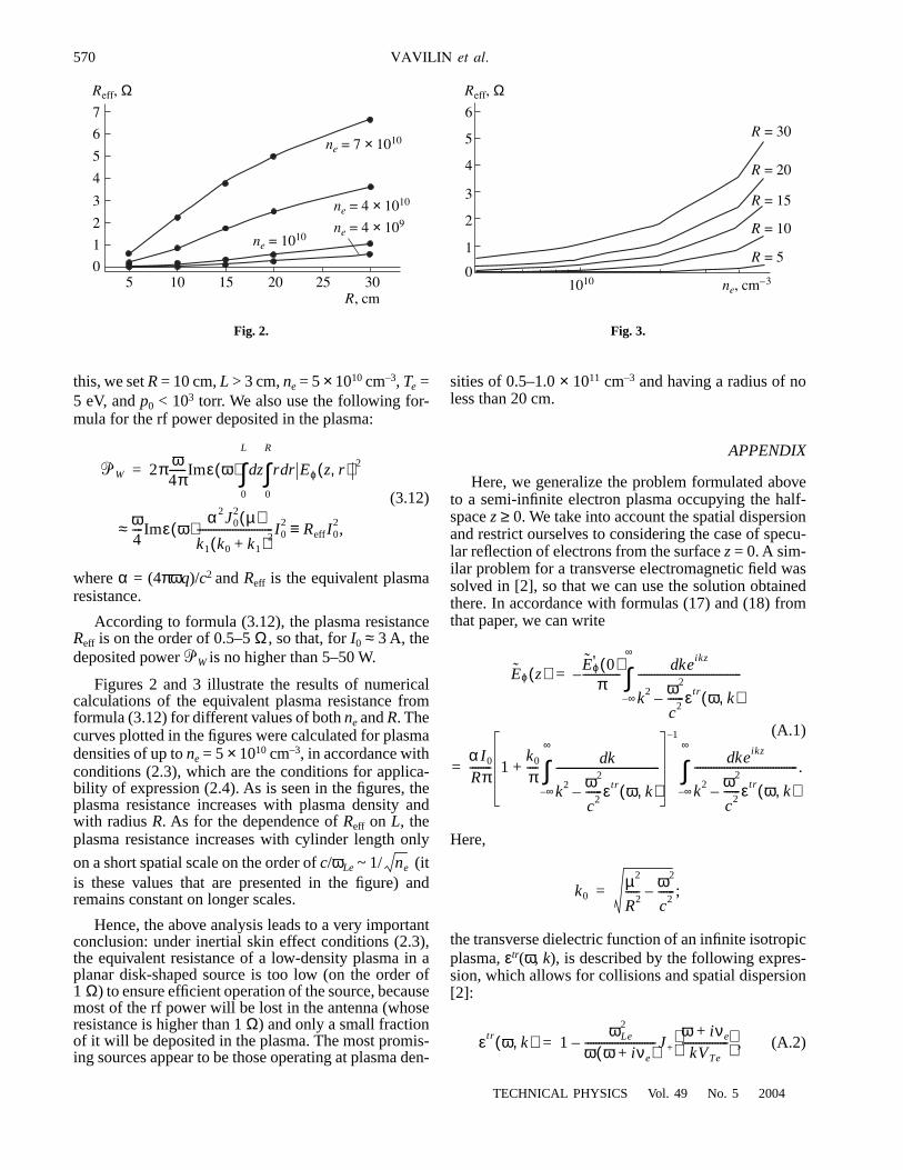
According to formula (3.12), the plasma resistanceReff is on the order of 0.5–5 Ω , so that, for I0 ≈ 3 A, thedeposited power 3W is no higher than 5–50 W.
Figures 2 and 3 illustrate the results of numericalcalculations of the equivalent plasma resistance fromformula (3.12) for different values of both ne and R. Thecurves plotted in the figures were calculated for plasmadensities of up to ne = 5 × 1010 cm–3, in accordance withconditions (2.3), which are the conditions for applica-bility of expression (2.4). As is seen in the figures, theplasma resistance increases with plasma density andwith radius R. As for the dependence of Reff on L, theplasma resistance increases with cylinder length only
on a short spatial scale on the order of c/ωLe ~ 1/ (itis these values that are presented in the figure) andremains constant on longer scales.
Hence, the above analysis leads to a very importantconclusion: under inertial skin effect conditions (2.3),the equivalent resistance of a low-density plasma in aplanar disk-shaped source is too low (on the order of1 Ω) to ensure efficient operation of the source, becausemost of the rf power will be lost in the antenna (whoseresistance is higher than 1 Ω) and only a small fractionof it will be deposited in the plasma. The most promis-ing sources appear to be those operating at plasma den-
3W 2π ω4π------Imε ω( ) z r r Eϕ z r,( ) 2d
0
R
∫d
0
L
∫=
≈ ω4----Imε ω( )
α2J02 µ( )
k1 k0 k1+( )2----------------------------I0
2 ReffI02,≡
ne
05 10 15 20 25
3
6ne = 7 × 10¹⁰
ne = 4 × 10¹⁰
R, cm
Reff, Ω
30
1
2
4
5
7
ne = 4 × 10⁹
ne = 1010
Fig. 2.
sities of 0.5–1.0 × 1011 cm–3 and having a radius of noless than 20 cm.
APPENDIX
Here, we generalize the problem formulated aboveto a semi-infinite electron plasma occupying the half-space z ≥ 0. We take into account the spatial dispersionand restrict ourselves to considering the case of specu-lar reflection of electrons from the surface z = 0. A sim-ilar problem for a transverse electromagnetic field wassolved in [2], so that we can use the solution obtainedthere. In accordance with formulas (17) and (18) fromthat paper, we can write
(A.1)
Here,
the transverse dielectric function of an infinite isotropicplasma, εtr(ω, k), is described by the following expres-sion, which allows for collisions and spatial dispersion[2]:
(A.2)
Eϕ z( ) Eϕ' 0( )π
-------------- keikzd
k2 ω2
c2------εtr ω k,( )–
--------------------------------------
∞–
∞
∫–=
= α I0
Rπ-------- 1
k0
π---- kd
k2 ω2
c2------εtr ω k,( )–
--------------------------------------
∞–
∞
∫+
–1
keikzd
k2 ω2
c2------εtr ω k,( )–
--------------------------------------.
∞–
∞
∫
k0µ2
R2----- ω2
c2------– ;=
εtr ω k,( ) 1ωLe
2
ω ω iνe+( )--------------------------J+
ω iνe+kVTe
----------------- ,–=
01010
3
6R = 30
R = 20
ne, cm–3
Reff, Ω
1
2
4
5
R = 15
R = 10
R = 5
Fig. 3.
TECHNICAL PHYSICS Vol. 49 No. 5 2004
LOW-POWER RF PLASMA SOURCES FOR TECHNOLOGICAL APPLICATIONS 571
where
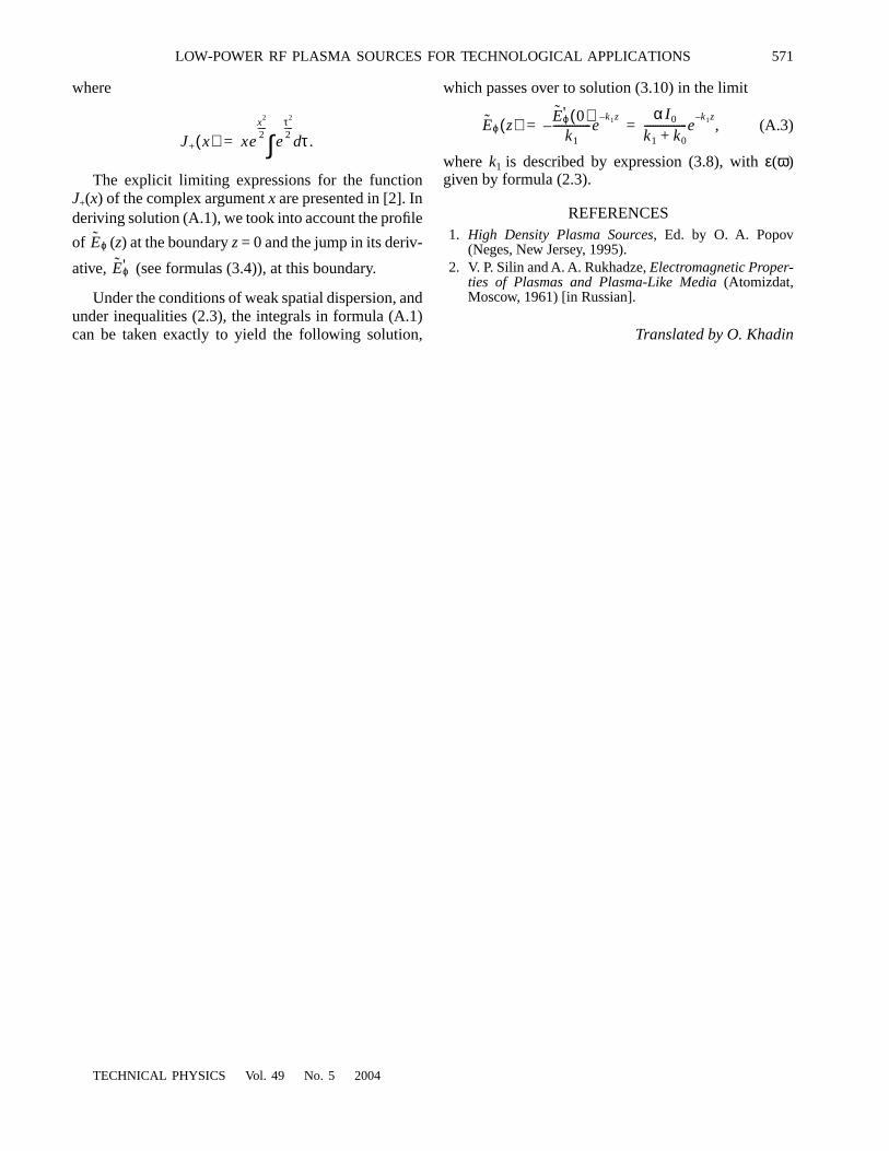
The explicit limiting expressions for the functionJ+(x) of the complex argument x are presented in [2]. Inderiving solution (A.1), we took into account the profile
of (z) at the boundary z = 0 and the jump in its deriv-
ative, (see formulas (3.4)), at this boundary.
Under the conditions of weak spatial dispersion, andunder inequalities (2.3), the integrals in formula (A.1)can be taken exactly to yield the following solution,
J+ x( ) xex
2
2-----
eτ2
2-----
τ .d∫=
Eϕ
Eϕ'
TECHNICAL PHYSICS Vol. 49 No. 5 2004
which passes over to solution (3.10) in the limit
(A.3)
where k1 is described by expression (3.8), with ε(ω)given by formula (2.3).
REFERENCES1. High Density Plasma Sources, Ed. by O. A. Popov
(Neges, New Jersey, 1995).2. V. P. Silin and A. A. Rukhadze, Electromagnetic Proper-
ties of Plasmas and Plasma-Like Media (Atomizdat,Moscow, 1961) [in Russian].
Translated by O. Khadin
Eϕ z( ) Eϕ' 0( )k1
--------------ek1z–
–α I0
k1 k0+----------------e
k1z–,= =