Embed Size (px)
Citation preview
Low Pressure Control Valves Models MT, DA, ADA
Installation and Maintenance
1
IM0006
Kimray Inc.- 52 NW 42nd Street Oklahoma City, Ok 73118 USA - Ph: (405) 525-6601, Fax: (405) 525-7520 - Kimray.com
April 2013
INTRODUCTIONCAUTION
Prior to installing, the instructions provided herein should be completely reviewed and understood before operating or repairing this equipment . All CAUTION and WARNING notes must be strictly observed to prevent personal injury or equipment damage.
ScopeThis installation manual includes instructions and maintenance information for the Kimray low pressure control valve.
Do not install, operate, or maintain a low pressure control valve without being fully trained and qualified with Kimray installation and maintenance manual. To avoid personal injury or property damage, it is important to carefully read, understand, and follow all the contents of this manual, including all safety cautions and warnings. If you have any questions about these instructions, contact your Kimray applications support group before proceeding.
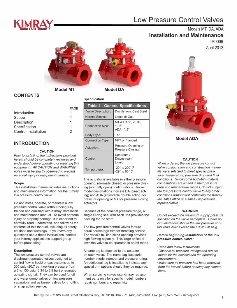
DescriptionThe low pressure control valves arediaphragm operated valves designed to control flow in liquid or gas systems up to 300 psig (20.7 bar) working pressure from a 5 to 100 psig (0.34 to 6.9 bar) pneumatic actuating signal. They can be used for oil and water dump valves on low pressure separators and as burner valves for throttling or snap action service.
CONTENTS
PAGEIntroduction 1Scope 1Description 1Specification 1Control Installation 2
Table 1 - General SpecificationsValve Description: Ductile Iron, Cast Steel
Normal Service: Liquid or Gas
Connection Size:MT & DA 1”, 2”, 3”, 4”, 6”ADA 1”, 2”
Body Style: Thru
Connection Type: NPT or Flanged
Actuation: Pressure Opening or Pressure Closing
Control:Upstream / Downstream Liquid
Temperature: -20° to 200° F-29° to 93° C
CAUTIONWhen ordered, the low pressure control valve configuration and construction materi-als were selected to meet specific pres-sure, temperature, pressure drop and fluid conditions. Since some body/trim material combinations are limited in their pressure drop and temperature ranges, do not subject the low pressure control valve to any other conditions without first contacting the Kimray Inc, sales office or a sales / applications representative
WARNINGDo not exceed the maximum supply pressure specified on the valve nameplate. Under no circumstances should the low pressure con-trol valve ever exceed the maximum psig.
Before beginning installation of the low pressure control valve:
•Read and follow instructions.•Observe all pressure, ratings and require ments for the devices and the operating environment.•Make sure all pressure has been removed from the vessel before opening any connec tions.
Specification
The actuator is available in either pressure opening, (normally closed) or pressure clos-ing (normally open) configurations. Valve model designations indicate DA (direct act-ing) and ADA (adjustable double acting) for pressure opening or MT for pressure closing actuators.
Because of the nominal pressure range, a single O-ring seal with back ups provides the packing for the stem.
The low pressure control valves feature equal percentage trim for throttling service. The valve’s full line-sized opening provides high flowing capacity. This large orifice al-lows the valve to be operated in on/off mode.
A name tag is attached to the actuator on each valve. The name tag lists serial number, model number and pressure rating. An additional tag is installed to indicate any special trim options should they be required.
When servicing valves use Kimray replace-ment parts only for specific model numbers, repair numbers and repair kits.
Model MT Model DA
Model ADA
Low Pressure Control Valves Models MT, DA, ADA
Installation and Maintenance
2
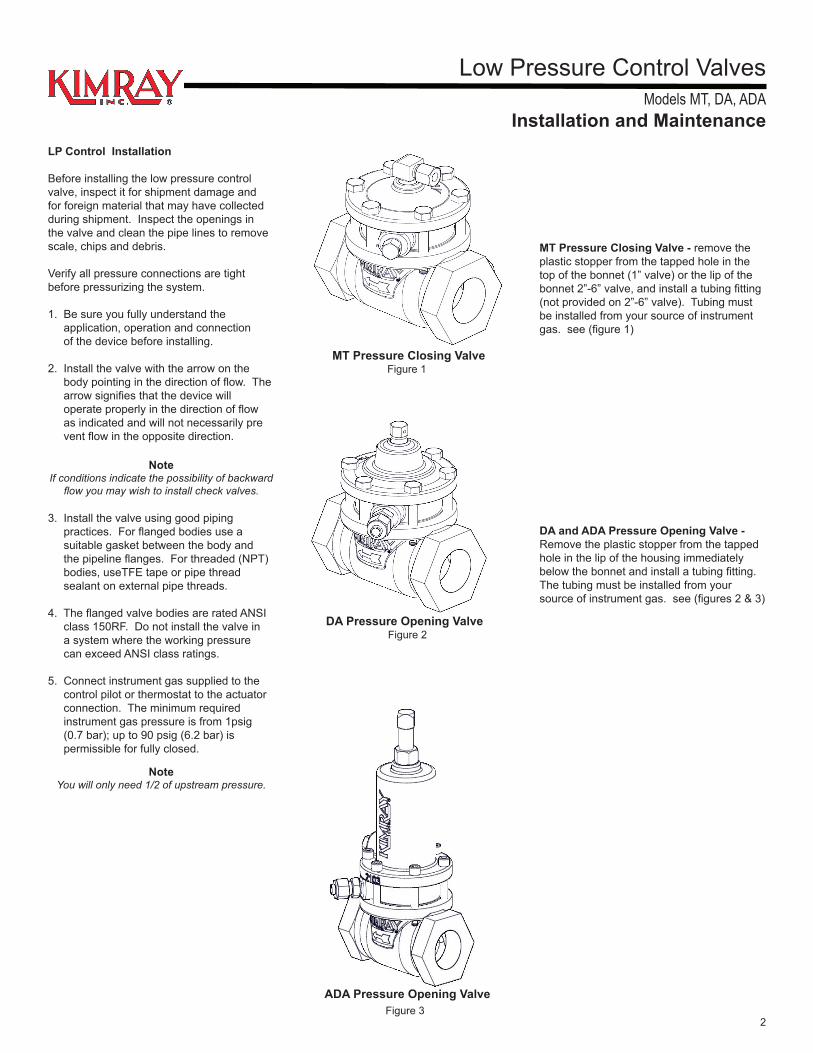
Figure 1
LP Control Installation
Before installing the low pressure control valve, inspect it for shipment damage and for foreign material that may have collected during shipment. Inspect the openings in the valve and clean the pipe lines to remove scale, chips and debris.
Verify all pressure connections are tight before pressurizing the system.
1. Be sure you fully understand the application, operation and connection of the device before installing.
2. Install the valve with the arrow on the body pointing in the direction of flow. The arrow signifies that the device will operate properly in the direction of flow as indicated and will not necessarily pre vent flow in the opposite direction.
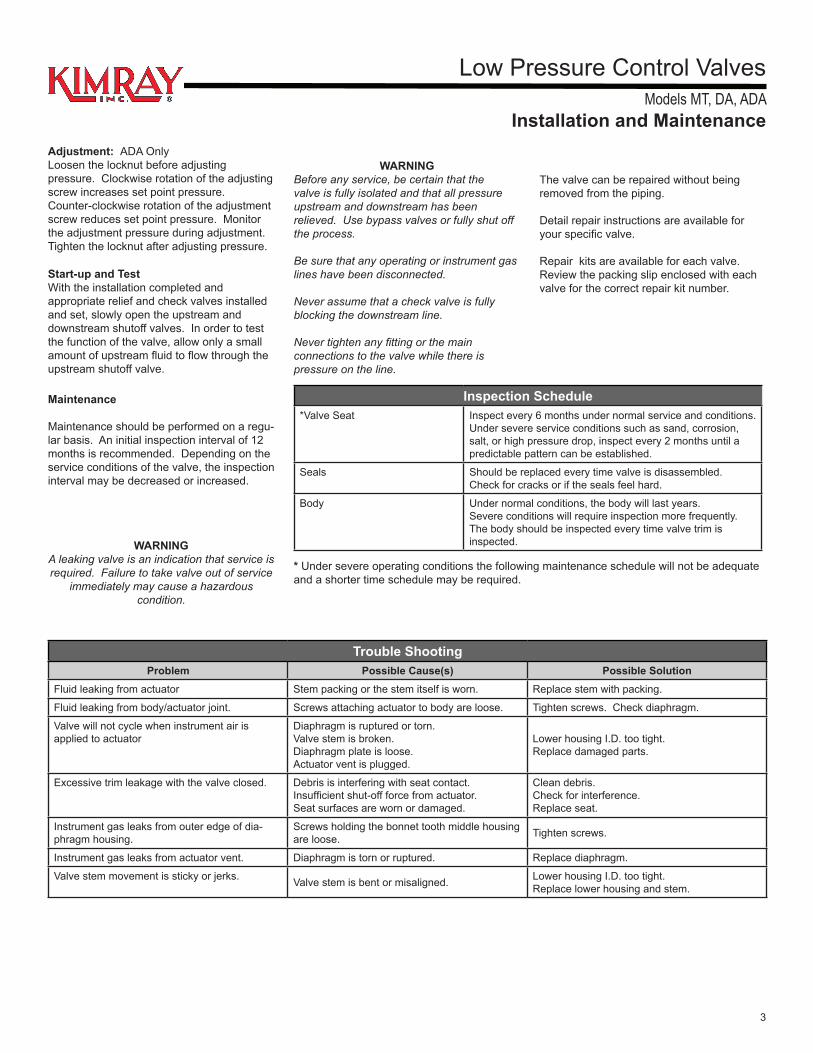
Figure 2
MT Pressure Closing Valve
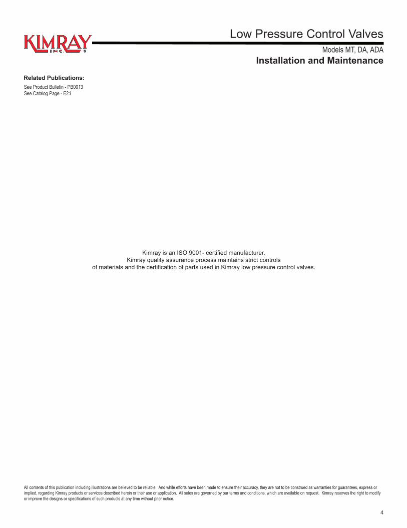
Figure 3
NoteIf conditions indicate the possibility of backward
flow you may wish to install check valves.
3. Install the valve using good piping practices. For flanged bodies use a suitable gasket between the body and the pipeline flanges. For threaded (NPT) bodies, useTFE tape or pipe thread sealant on external pipe threads.
4. The flanged valve bodies are rated ANSI class 150RF. Do not install the valve in a system where the working pressure can exceed ANSI class ratings.
5. Connect instrument gas supplied to the control pilot or thermostat to the actuator connection. The minimum required instrument gas pressure is from 1psig (0.7 bar); up to 90 psig (6.2 bar) is permissible for fully closed.
MT Pressure Closing Valve - remove the plastic stopper from the tapped hole in the top of the bonnet (1” valve) or the lip of the bonnet 2”-6” valve, and install a tubing fitting (not provided on 2”-6” valve). Tubing must be installed from your source of instrument gas. see (figure 1)
DA and ADA Pressure Opening Valve - Remove the plastic stopper from the tapped hole in the lip of the housing immediately below the bonnet and install a tubing fitting. The tubing must be installed from your source of instrument gas. see (figures 2 & 3)
DA Pressure Opening Valve
ADA Pressure Opening Valve
NoteYou will only need 1/2 of upstream pressure.
Low Pressure Control Valves Models MT, DA, ADA
Installation and Maintenance
3
Trouble ShootingProblem Possible Cause(s) Possible Solution
Fluid leaking from actuator Stem packing or the stem itself is worn. Replace stem with packing.
Fluid leaking from body/actuator joint. Screws attaching actuator to body are loose. Tighten screws. Check diaphragm.
Valve will not cycle when instrument air is applied to actuator
Diaphragm is ruptured or torn.Valve stem is broken.Diaphragm plate is loose.Actuator vent is plugged.
Lower housing I.D. too tight.Replace damaged parts.
Excessive trim leakage with the valve closed. Debris is interfering with seat contact.Insufficient shut-off force from actuator.Seat surfaces are worn or damaged.
Clean debris. Check for interference.Replace seat.
Instrument gas leaks from outer edge of dia-phragm housing.
Screws holding the bonnet tooth middle housing are loose. Tighten screws.
Instrument gas leaks from actuator vent. Diaphragm is torn or ruptured. Replace diaphragm.
Valve stem movement is sticky or jerks. Valve stem is bent or misaligned. Lower housing I.D. too tight. Replace lower housing and stem.
Maintenance
Maintenance should be performed on a regu-lar basis. An initial inspection interval of 12 months is recommended. Depending on the service conditions of the valve, the inspection interval may be decreased or increased.
The valve can be repaired without being removed from the piping.
Detail repair instructions are available for your specific valve.
Repair kits are available for each valve. Review the packing slip enclosed with each valve for the correct repair kit number.
WARNINGA leaking valve is an indication that service is required. Failure to take valve out of service
immediately may cause a hazardous condition.
Inspection Schedule*Valve Seat Inspect every 6 months under normal service and conditions.
Under severe service conditions such as sand, corrosion, salt, or high pressure drop, inspect every 2 months until a predictable pattern can be established.
Seals Should be replaced every time valve is disassembled. Check for cracks or if the seals feel hard.
Body Under normal conditions, the body will last years. Severe conditions will require inspection more frequently. The body should be inspected every time valve trim is inspected.
* Under severe operating conditions the following maintenance schedule will not be adequate and a shorter time schedule may be required.
Start-up and TestWith the installation completed and appropriate relief and check valves installed and set, slowly open the upstream and downstream shutoff valves. In order to test the function of the valve, allow only a small amount of upstream fluid to flow through the upstream shutoff valve.
WARNINGBefore any service, be certain that the valve is fully isolated and that all pressure upstream and downstream has been relieved. Use bypass valves or fully shut off the process.
Be sure that any operating or instrument gas lines have been disconnected.
Never assume that a check valve is fully blocking the downstream line.
Never tighten any fitting or the main connections to the valve while there is pressure on the line.
Adjustment: ADA OnlyLoosen the locknut before adjusting pressure. Clockwise rotation of the adjusting screw increases set point pressure. Counter-clockwise rotation of the adjustment screw reduces set point pressure. Monitor the adjustment pressure during adjustment. Tighten the locknut after adjusting pressure.
Low Pressure Control Valves Models MT, DA, ADA
Installation and Maintenance
4
Kimray is an ISO 9001- certified manufacturer.Kimray quality assurance process maintains strict controls
of materials and the certification of parts used in Kimray low pressure control valves.
All contents of this publication including illustrations are believed to be reliable. And while efforts have been made to ensure their accuracy, they are not to be construed as warranties for guarantees, express or implied, regarding Kimray products or services described herein or their use or application. All sales are governed by our terms and conditions, which are available on request. Kimray reserves the right to modify or improve the designs or specifications of such products at any time without prior notice.
Related Publications:See Product Bulletin - PB0013See Catalog Page - E2:i