Embed Size (px)
DESCRIPTION
Article
Citation preview
Progress In Electromagnetics Research, Vol. 121, 121–139, 2011
LOW-PROFILE DIRECTIONAL ULTRA-WIDEBAND AN-TENNA FOR SEE-THROUGH-WALL IMAGING APPLI-CATIONS
F. Zhu1, *, S. Gao1, A. T. S. Ho2, T. W. C. Brown3, J. Z. Li4,and J. D. Xu4
1Surrey Space Centre, University of Surrey, Guildford, GU2 7XH, UK2Department of Computing, University of Surrey, Guildford, GU27XH, UK3Centre for Communication Systems Research, University of Surrey,GU2 7XH, UK4Northwestern Polytechnical University, Xi’an 710072, China
Abstract—A compact-size planar antenna with ultra-wideband(UWB) bandwidth and directional patterns is presented. The antennacan be fabricated on a printed circuit board (PCB). On one side ofthe PCB, it has a circular patch, and on the other side it has aslot-embedded ground plane with a fork-shaped feeding stub in theslot. Directional radiation is achieved by using a reflector below theantenna. To reduce the thickness of the antenna, a new low-profileantenna configuration is proposed. Three types of directional UWBantennas are analyzed. The distance between the antenna and thereflector is 12mm (0.16λ0, λ0 is the free space wavelength at thelowest frequency). In order to validate the design, a prototype isalso fabricated and measured. Measured results agree well with thesimulated ones. The measured results confirm that the proposedantenna features a reflection coefficient below −10 dB over the UWBrange from 4.2 GHz to 8.5 GHz, a maximum gain around 9 dBi, afront-to-back ratio over 17 dB and pulse fidelity higher than 90% inthe time domain. Thus it is promising for see-through-wall imagingapplications.
Received 9 August 2011, Accepted 13 October 2011, Scheduled 19 October 2011* Corresponding author: Fuguo Zhu ([email protected]).
122 Zhu et al.
1. INTRODUCTION
Ultra-wideband through the wall imaging (TWI) radar has attractedmuch attention in both academic and industrial communities as ithas important applications in homeland security, fire and rescue incollapsed buildings and natural disaster situations such as earthquakesand hurricanes [1].
There are a few companies and laboratories which work on theUWB TWI radars. Involved systems and prototypes include thefollowing: 1) Radar Vision 1000 [2] and 2000 [3] from Time DomainCompany; 2) Prism 200 [4] from Cambridge Cons.; 3) ImpSAR [5] fromEureka Aerospace Company; 4) Xaver 800 [6] from Camero Technology.Among them, Xaver 800 is the latest product which operates from3GHz to 10 GHz. It provides high resolution images of 20 mm throughmost common wall materials. Novelda Company [7] produces someUWB radar modules which can be integrated with UWB antennas.
In addition to those listed above, the following laborato-ries/universities are also working on the UWB TWI radars: DefenceR&D Canada, Kyoto University, Delft University of Technology, Uni-versity of Tennessee, and Center for Advanced Communications at Vil-lanova University. A real-time see-through-wall radar system [8] basedon FPGA is designed and implemented in the University of Tennessee.It covers dual frequency bands. One frequency range extends from2GHz to 4 GHz; the other frequency range is from 7 GHz to 13 GHz.
The UWB frequency band from 3.1 to 10.6GHz with themaximum power spectral density of −41.3 dBm/MHz allocated bythe Federal Communications Commission (FCC) has accelerated theresearch of UWB radar system since 2002 [9]. In the UK, the Officefor Communications (OfCom) also established a standard in 2007 forUWB radars [10]. The UK OfCom regulations defines a frequencyrange for UWB radar which includes a 600 MHz band centered at4.5GHz, and a 2.5 GHz band centered at 7.25 GHz. Compared withtraditional radar, UWB radar has many advantages such as highresolution, resistance to multipath phenomenon, extremely low poweremission and low power consumption.
The design of directional UWB antennas is the key issue of UWBradars. Though many UWB antennas are available in the literature,most of them are for UWB communications which require omni-directional patterns. The aim of this project is to investigate noveldesigns of low-cost and small antennas suitable for UWB through thewall imaging radars.
Main challenges of the UWB antenna design for radars includeimpedance matching, low distortion of pulses, directional patterns,
Progress In Electromagnetics Research, Vol. 121, 2011 123
high front-to-back ratio for rejecting false alarms from the movementof the user holding the device, compact size and low cost. In theliterature, the widely used antennas for UWB radar are horn [11, 12]and Vivaldi antennas [8, 13, 14]. Both types of antennas can producebroadband impedance matching and directional patterns. The hornantenna is bulky in size, while the Vivaldi antenna is planar and canbe easily implemented in arrays. In [13, 14], a 16 × 16 antipodalVivaldi antenna array antenna has been used at the receiver forUWB through wall imaging with synthetic aperture radar (SAR)algorithm. However, Vivaldi antenna is large in size as it has tobe at least a few wavelengths at the lowest frequency for obtainingdirectional radiations and good impedance matching [14]. Otherdirectional wideband antennas include coaxial fed suspended patchantennas [15–18], and cavity backed antennas [19–21]. Some techniquesto achieve directional patterns are available in the literature, whichinclude the use of lossy absorbing materials [22] or a reflector belowthe radiating element [23–26]. The use of lossy absorbing material,however, may lead to low radiation efficiency. Regarding the useof reflectors, different types of reflectors have been used, such ascorner reflector [23], pyramidal reflecting ground plane [24] and planarreflector [25, 26]. Compared with the use of corner reflector andpyramidal reflector ground plane, the directional UWB antenna witha planar reflector has low fabrication cost and is easy to implement inUWB arrays. In [26], a directional UWB array has been realized byusing four pairs of leaf-shaped bowtie elements and a flat aluminiumplate as a reflector. Recently, various planar monopoles have beenreported [27–31]. In [32], a compact UWB UHF array antenna hasbeen developed for through wall radar by using the printed ellipticalmonopole antenna. However, it performs a bidirectional patternwithout a shielding element. Reported in [33], a small size directionalantenna has been proposed for UWB wireless personal area networks(WPAN) and wireless body area networks (WBAN) by employing aslot monopole antenna and a small size reflector. It has a poor front-to-back ratio (< 10 dB) due to its small size reflector.
The main problem of the directional UWB antenna with a reflectoris the thickness of the antenna, as the reflector usually needs to belocated at a distance of about 1/4 wavelength from the antenna [23].For portable radar system applications, it is necessary to reduce boththe thickness and the size of the antenna, which is the motivation ofthis work.
In this paper, a low profile directional UWB antenna is proposed.The paper is organized as follows: Section 2 shows the configurationsand comparisons of two reference antennas with directional patterns.
124 Zhu et al.
A novel directional UWB antenna is proposed in Section 3. Theresults of parametric study and analysis of current distribution arecarried out in this section. Both simulated and measured results ofreflection coefficients and radiation patterns are illustrated in Section 4.The transient result of the proposed directional UWB antennademonstrates its capability for impulse radar system. Section 5 givesthe conclusion.
2. CONFIGURATION AND RESULTS OF TWOREFERENCE ANTENNAS
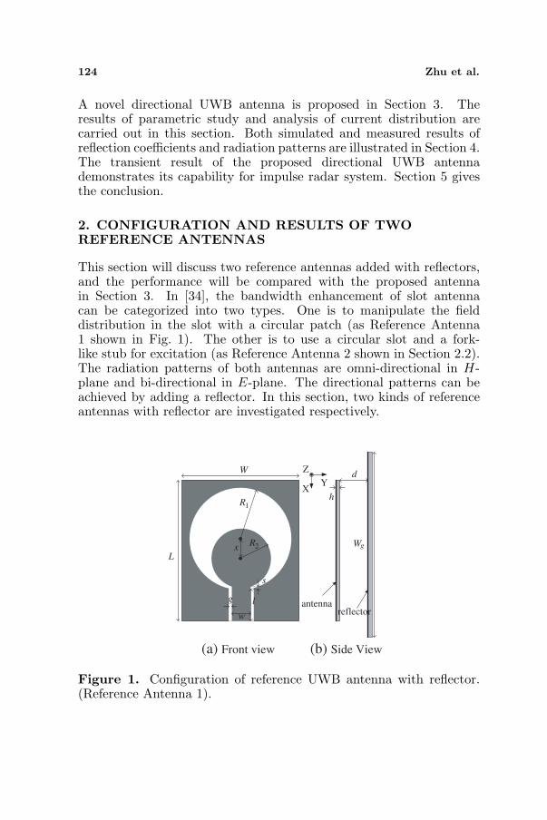
This section will discuss two reference antennas added with reflectors,and the performance will be compared with the proposed antennain Section 3. In [34], the bandwidth enhancement of slot antennacan be categorized into two types. One is to manipulate the fielddistribution in the slot with a circular patch (as Reference Antenna1 shown in Fig. 1). The other is to use a circular slot and a fork-like stub for excitation (as Reference Antenna 2 shown in Section 2.2).The radiation patterns of both antennas are omni-directional in H-plane and bi-directional in E-plane. The directional patterns can beachieved by adding a reflector. In this section, two kinds of referenceantennas with reflector are investigated respectively.
W
L
dZ
XY
hR1
R2
s
x
g
w
l
Wg
antennareflector
(a) Front view (b) Side View
Figure 1. Configuration of reference UWB antenna with reflector.(Reference Antenna 1).
Progress In Electromagnetics Research, Vol. 121, 2011 125
3.0 3.5 4.0 4.5 5.0 5.5 6.0 6.5 7.0 7.5 8.0 8.5 9.0-20
-15
-10
-5
0
Frequency (GHz)
no reflector
d = 12 mm
d = 14 mm
d = 16 mm
S11
(dB
)
Figure 2. Simulated reflection coefficients in terms of d compared tothe case of no reflector. (Reference Antenna 1).
2.1. Reference Antenna 1 — Coplanar Waveguide (CPW)Fed UWB Slot Antenna
Figure 1 shows the configuration of reference UWB antenna with areflector. This antenna is denoted as reference antenna 1. The optimalvalue of s should not be larger than the thickness of the substrateh [31]. The Duroid5880 substrate with dielectric constant of 2.2 andthickness of 1.575 mm is used in this project. The frequency band ofthe designed UWB antenna is from 4.2 GHz to 8.5GHz which coversthe UWB band of OfCom, UK. The slot aperture depends on the lowestfrequency of operation (f1 = 4.2GHz) approximately [31]:
R1 ≈ c
4f1
√1+εr
2
× 2π
(1)
R2 ≈ R1
2(2)
Dimensions of the UWB antenna are as follows: W = 30mm, L =34mm, R1 = 13.7 mm, R2 = 7.5mm, x = 5.3mm, w = 3.6mm,g = 0.2mm, l = 5.45 mm, s = 1.0mm. To achieve directional patterns,the reflector with a dimension of 50 mm × 50mm is added to increasethe directivity. Fig. 2 shows the effect of various distances betweenreflector and antenna on the reflection coefficients versus frequency.It shows that, compared to the original antenna without a reflector,the impedance matching of the antenna has been strongly affected bythe reflector, especially at lowest frequencies. The lowest frequencyfor S11 < −10 dB shifts from 6.7 GHz to 5.8 GHz when the distance
126 Zhu et al.
increases from 12 mm to 16mm, however, this leads to a bulky antenna.
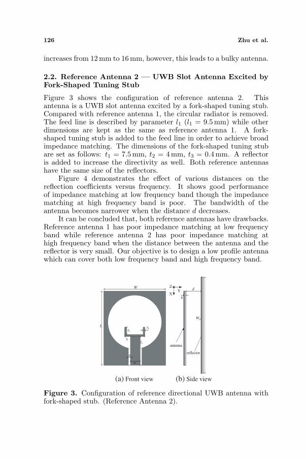
2.2. Reference Antenna 2 — UWB Slot Antenna Excited byFork-Shaped Tuning Stub
Figure 3 shows the configuration of reference antenna 2. Thisantenna is a UWB slot antenna excited by a fork-shaped tuning stub.Compared with reference antenna 1, the circular radiator is removed.The feed line is described by parameter l1 (l1 = 9.5mm) while otherdimensions are kept as the same as reference antenna 1. A fork-shaped tuning stub is added to the feed line in order to achieve broadimpedance matching. The dimensions of the fork-shaped tuning stubare set as follows: t1 = 7.5mm, t2 = 4 mm, t3 = 0.4mm. A reflectoris added to increase the directivity as well. Both reference antennashave the same size of the reflectors.
Figure 4 demonstrates the effect of various distances on thereflection coefficients versus frequency. It shows good performanceof impedance matching at low frequency band though the impedancematching at high frequency band is poor. The bandwidth of theantenna becomes narrower when the distance d decreases.
It can be concluded that, both reference antennas have drawbacks.Reference antenna 1 has poor impedance matching at low frequencyband while reference antenna 2 has poor impedance matching athigh frequency band when the distance between the antenna and thereflector is very small. Our objective is to design a low profile antennawhich can cover both low frequency band and high frequency band.
antenna
reflector
XY
ZW
Lt2
t3
t1l1
g
w
h
d
Wg
(a) Front view (b) Side view
Figure 3. Configuration of reference directional UWB antenna withfork-shaped stub. (Reference Antenna 2).
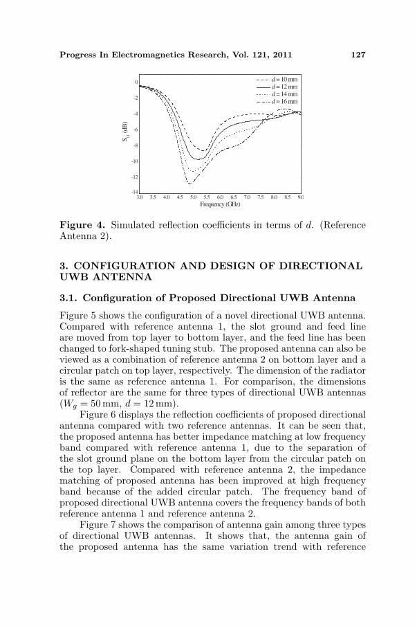
Progress In Electromagnetics Research, Vol. 121, 2011 127
3.0 3.5 4.0 4.5 5.0 5.5 6.0 6.5 7.0 7.5 8.0 8.5 9.0-14
-12
-10
-8
-6
-4
-2
0
Frequency (GHz)
d = 10 mm
d = 12 mm
d = 14 mm
d = 16 mm
S11
(dB
)
Figure 4. Simulated reflection coefficients in terms of d. (ReferenceAntenna 2).
3. CONFIGURATION AND DESIGN OF DIRECTIONALUWB ANTENNA
3.1. Configuration of Proposed Directional UWB Antenna
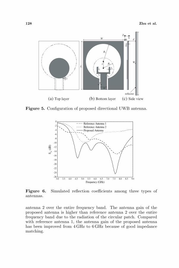
Figure 5 shows the configuration of a novel directional UWB antenna.Compared with reference antenna 1, the slot ground and feed lineare moved from top layer to bottom layer, and the feed line has beenchanged to fork-shaped tuning stub. The proposed antenna can also beviewed as a combination of reference antenna 2 on bottom layer and acircular patch on top layer, respectively. The dimension of the radiatoris the same as reference antenna 1. For comparison, the dimensionsof reflector are the same for three types of directional UWB antennas(Wg = 50 mm, d = 12 mm).
Figure 6 displays the reflection coefficients of proposed directionalantenna compared with two reference antennas. It can be seen that,the proposed antenna has better impedance matching at low frequencyband compared with reference antenna 1, due to the separation ofthe slot ground plane on the bottom layer from the circular patch onthe top layer. Compared with reference antenna 2, the impedancematching of proposed antenna has been improved at high frequencyband because of the added circular patch. The frequency band ofproposed directional UWB antenna covers the frequency bands of bothreference antenna 1 and reference antenna 2.
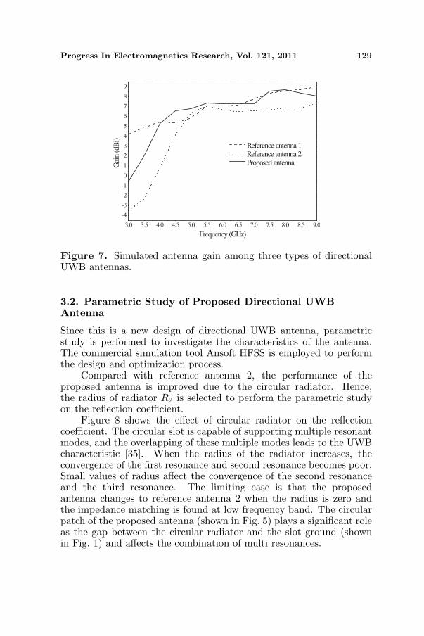
Figure 7 shows the comparison of antenna gain among three typesof directional UWB antennas. It shows that, the antenna gain ofthe proposed antenna has the same variation trend with reference
128 Zhu et al.
reflector
Z
XY
s
L
W
R1
R2x
t2
t1
t3
l1
g
w
d
h
Wg
(a) Top layer (b) Bottom layer (c) Side view
Figure 5. Configuration of proposed directional UWB antenna.
3.0 3.5 4.0 4.5 5.0 5.5 6.0 6.5 7.0 7.5 8.0 8.5 9.0-26
-24
-22
-20
-18
-16
-14
-12
-10
-8
-6
-4
-2
0
Frequency (GHz)
Reference Antenna 1 Reference Antenna 2 Proposed Antenna
S11
(dB
)
Figure 6. Simulated reflection coefficients among three types ofantennas.
antenna 2 over the entire frequency band. The antenna gain of theproposed antenna is higher than reference antenna 2 over the entirefrequency band due to the radiation of the circular patch. Comparedwith reference antenna 1, the antenna gain of the proposed antennahas been improved from 4GHz to 6 GHz because of good impedancematching.
Progress In Electromagnetics Research, Vol. 121, 2011 129
3.0 3.5 4.0 4.5 5.0 5.5 6.0 6.5 7.0 7.5 8.0 8.5 9.0
-4
-3
-2
-1
0
1
2
3
4
5
6
7
8
9
Gai
n (d
Bi)
Frequency (GHz)
Reference antenna 1 Reference antenna 2 Proposed antenna
Figure 7. Simulated antenna gain among three types of directionalUWB antennas.
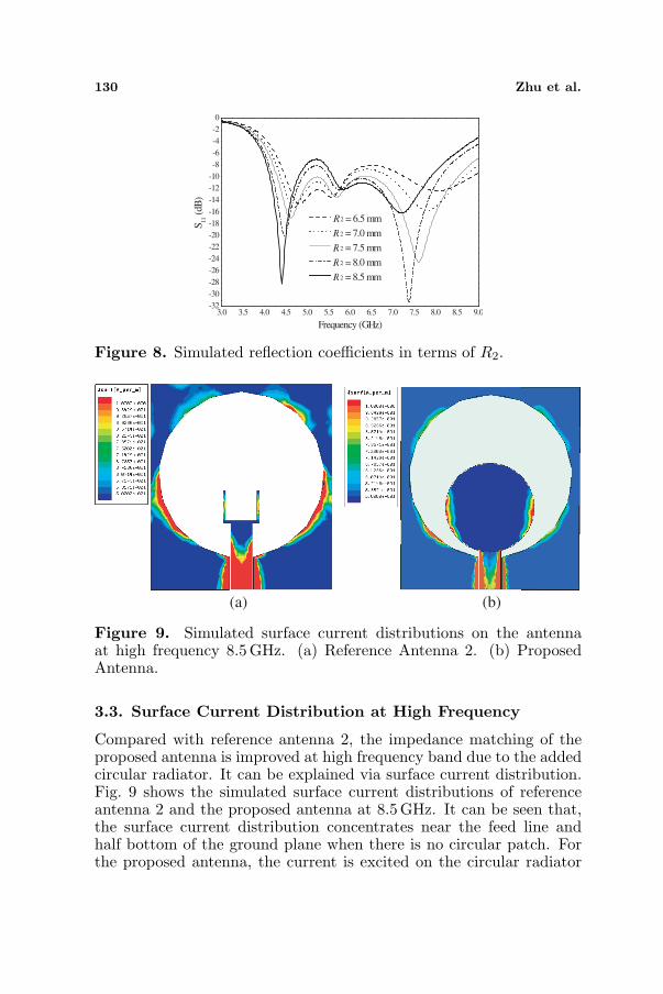
3.2. Parametric Study of Proposed Directional UWBAntenna
Since this is a new design of directional UWB antenna, parametricstudy is performed to investigate the characteristics of the antenna.The commercial simulation tool Ansoft HFSS is employed to performthe design and optimization process.
Compared with reference antenna 2, the performance of theproposed antenna is improved due to the circular radiator. Hence,the radius of radiator R2 is selected to perform the parametric studyon the reflection coefficient.
Figure 8 shows the effect of circular radiator on the reflectioncoefficient. The circular slot is capable of supporting multiple resonantmodes, and the overlapping of these multiple modes leads to the UWBcharacteristic [35]. When the radius of the radiator increases, theconvergence of the first resonance and second resonance becomes poor.Small values of radius affect the convergence of the second resonanceand the third resonance. The limiting case is that the proposedantenna changes to reference antenna 2 when the radius is zero andthe impedance matching is found at low frequency band. The circularpatch of the proposed antenna (shown in Fig. 5) plays a significant roleas the gap between the circular radiator and the slot ground (shownin Fig. 1) and affects the combination of multi resonances.
130 Zhu et al.
3.0 3.5 4.0 4.5 5.0 5.5 6.0 6.5 7.0 7.5 8.0 8.5 9.0-32
-30
-28
-26
-24
-22
-20
-18
-16
-14
-12
-10
-8
-6
-4
-2
0
Frequency (GHz)
R2 = 6.5 mm
R2 = 7.0 mm
R2 = 7.5 mm
R2 = 8.0 mm
R2 = 8.5 mm
S11
(dB
)
Figure 8. Simulated reflection coefficients in terms of R2.
(a) (b)
Figure 9. Simulated surface current distributions on the antennaat high frequency 8.5 GHz. (a) Reference Antenna 2. (b) ProposedAntenna.
3.3. Surface Current Distribution at High Frequency
Compared with reference antenna 2, the impedance matching of theproposed antenna is improved at high frequency band due to the addedcircular radiator. It can be explained via surface current distribution.Fig. 9 shows the simulated surface current distributions of referenceantenna 2 and the proposed antenna at 8.5GHz. It can be seen that,the surface current distribution concentrates near the feed line andhalf bottom of the ground plane when there is no circular patch. Forthe proposed antenna, the current is excited on the circular radiator
Progress In Electromagnetics Research, Vol. 121, 2011 131
and it is accounting for the gain improvement compared with referenceantenna 2. The added circular patch causes the spreading out of thesurface current on the whole ground plane [36] and it will result ingood performance of bandwidth broadening at higher frequencies.
4. SIMULATED AND MEASURED RESULTS
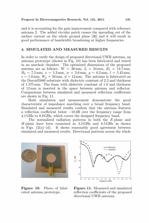
In order to verify the design of proposed directional UWB antenna, anantenna prototype (shown in Fig. 10) has been fabricated and testedin an anechoic chamber. The optimized dimensions of the proposedantenna are as follows: W = 30mm, L = 34 mm, R1 = 13.7mm,R2 = 7.5 mm, x = 5.3mm, w = 3.6mm, g = 0.2mm, l = 5.45mm,s = 1.0mm, Wg = 50 mm, d = 12 mm. The antenna is fabricated onthe Duroid5880 substrate with dielectric constant of 2.2 and thicknessof 1.575mm. The foam with dielectric constant of 1.0 and thicknessof 12 mm is inserted in the space between antenna and reflector.Comparisons between simulated and measured reflection coefficientsare shown in Fig. 11.
Both simulation and measurement demonstrate the goodcharacteristic of impedance matching over a broad frequency band.Simulated and measured results confirm that the antenna featuresa reflection coefficient below −10 dB over the frequency range from4.1GHz to 8.9 GHz, which covers the designed frequency band.
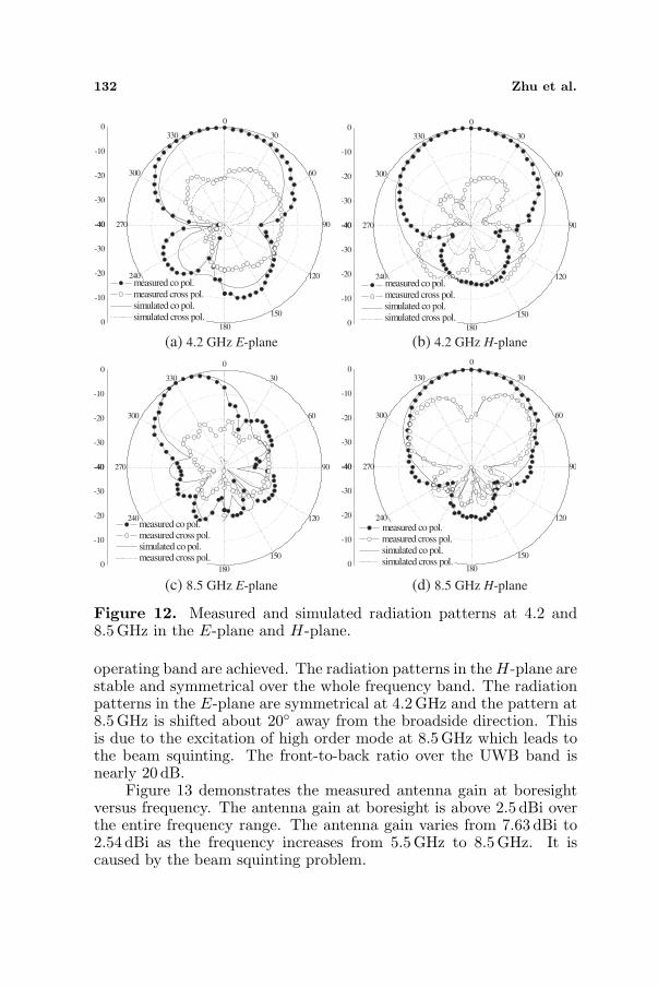
The normalized radiation patterns in both the E-plane andH-plane have been examined at 4.2 GHz and 8.5 GHz as shownin Figs. 12(a)–(d). It shows reasonably good agreement betweensimulated and measured results. Directional patterns across the whole
Figure 10. Photo of fabri-cated antenna prototype.
3.0 3.5 4.0 4.5 5.0 5.5 6.0 6.5 7.0 7.5 8.0 8.5 9.0
-25
-20
-15
-10
-5
0
S11
(dB
)
Frequency (GHz)
Measured Simulated
Figure 11. Measured and simulatedreflection coefficients of the proposeddirectional UWB antenna.
132 Zhu et al.
-40
-30
-20
-10
00
30
60
90
120
150
180
210
240
270
300
330
-40
-30
-20
-10
0
measured co pol. measured cross pol. simulated co pol. simulated cross pol.
-40
-30
-20
-10
00
30
60
90
120
150
180
210
240
270
300
330
-40
-30
-20
-10
0
measured co pol. measured cross pol. simulated co pol. simulated cross pol.
-40
-30
-20
-10
00
30
60
90
120
150
180
210
240
270
300
330
-40
-30
-20
-10
0
measured co pol. measured cross pol. simulated co pol. measured cross pol.
-40
-30
-20
-10
00
30
60
90
120
150
180
210
240
270
300
330
-40
-30
-20
-10
0
measured co pol. measured cross pol. simulated co pol. simulated cross pol.
(a) 4.2 GHz E-plane (b) 4.2 GHz H-plane
(c) 8.5 GHz E-plane (d) 8.5 GHz H-plane
Figure 12. Measured and simulated radiation patterns at 4.2 and8.5GHz in the E-plane and H-plane.
operating band are achieved. The radiation patterns in the H-plane arestable and symmetrical over the whole frequency band. The radiationpatterns in the E-plane are symmetrical at 4.2GHz and the pattern at8.5GHz is shifted about 20◦ away from the broadside direction. Thisis due to the excitation of high order mode at 8.5 GHz which leads tothe beam squinting. The front-to-back ratio over the UWB band isnearly 20 dB.
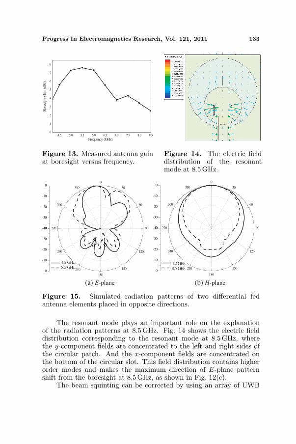
Figure 13 demonstrates the measured antenna gain at boresightversus frequency. The antenna gain at boresight is above 2.5 dBi overthe entire frequency range. The antenna gain varies from 7.63 dBi to2.54 dBi as the frequency increases from 5.5GHz to 8.5 GHz. It iscaused by the beam squinting problem.
Progress In Electromagnetics Research, Vol. 121, 2011 133
4.5 5.0 5.5 6.0 6.5 7.0 7.5 8.0 8.50
1
2
3
4
5
6
7
8
Bor
esig
ht G
ain
(dB
i)
Frequency (GHz)
Figure 13. Measured antenna gainat boresight versus frequency.
Figure 14. The electric fielddistribution of the resonantmode at 8.5 GHz.
-40
-30
-20
-10
00
30
60
90
120
150
180
210
240
270
300
330
-40
-30
-20
-10
0 4.2 GHz 8.5 GHz
-40
-30
-20
-10
00
30
60
90
120
150
180
210
240
270
300
330
-40
-30
-20
-10
0
4.2 GHz 8.5 GHz
(a) E-plane (b) H-plane
Figure 15. Simulated radiation patterns of two differential fedantenna elements placed in opposite directions.
The resonant mode plays an important role on the explanationof the radiation patterns at 8.5 GHz. Fig. 14 shows the electric fielddistribution corresponding to the resonant mode at 8.5 GHz, wherethe y-component fields are concentrated to the left and right sides ofthe circular patch. And the x-component fields are concentrated onthe bottom of the circular slot. This field distribution contains higherorder modes and makes the maximum direction of E-plane patternshift from the boresight at 8.5GHz, as shown in Fig. 12(c).
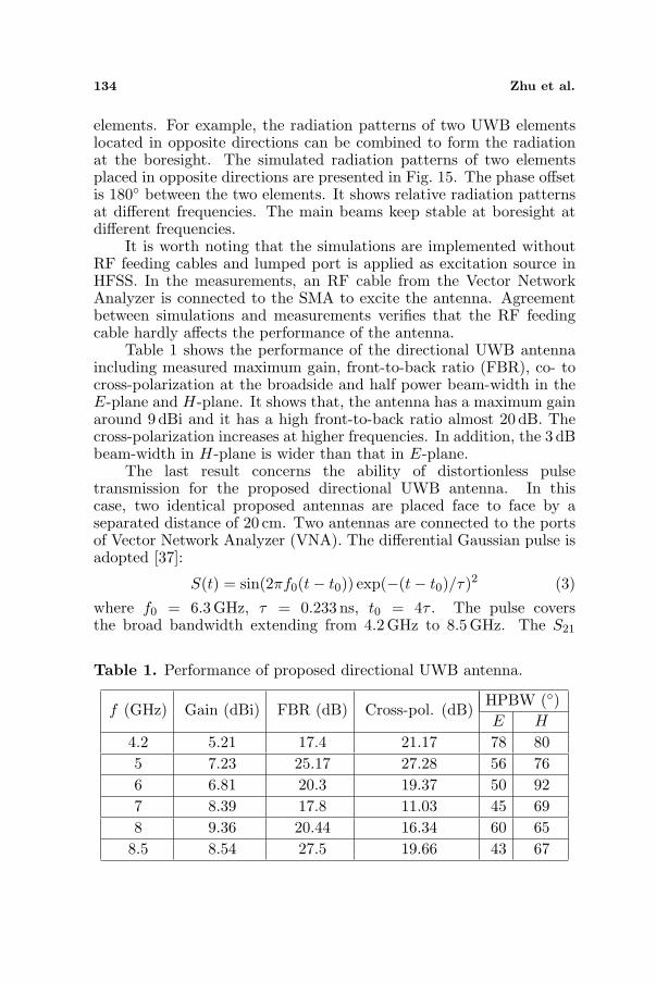
The beam squinting can be corrected by using an array of UWB
134 Zhu et al.
elements. For example, the radiation patterns of two UWB elementslocated in opposite directions can be combined to form the radiationat the boresight. The simulated radiation patterns of two elementsplaced in opposite directions are presented in Fig. 15. The phase offsetis 180◦ between the two elements. It shows relative radiation patternsat different frequencies. The main beams keep stable at boresight atdifferent frequencies.
It is worth noting that the simulations are implemented withoutRF feeding cables and lumped port is applied as excitation source inHFSS. In the measurements, an RF cable from the Vector NetworkAnalyzer is connected to the SMA to excite the antenna. Agreementbetween simulations and measurements verifies that the RF feedingcable hardly affects the performance of the antenna.
Table 1 shows the performance of the directional UWB antennaincluding measured maximum gain, front-to-back ratio (FBR), co- tocross-polarization at the broadside and half power beam-width in theE-plane and H-plane. It shows that, the antenna has a maximum gainaround 9 dBi and it has a high front-to-back ratio almost 20 dB. Thecross-polarization increases at higher frequencies. In addition, the 3 dBbeam-width in H-plane is wider than that in E-plane.
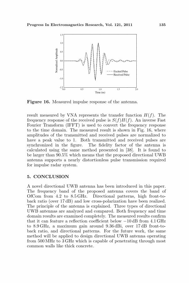
The last result concerns the ability of distortionless pulsetransmission for the proposed directional UWB antenna. In thiscase, two identical proposed antennas are placed face to face by aseparated distance of 20 cm. Two antennas are connected to the portsof Vector Network Analyzer (VNA). The differential Gaussian pulse isadopted [37]:
S(t) = sin(2πf0(t− t0)) exp(−(t− t0)/τ)2 (3)
where f0 = 6.3GHz, τ = 0.233 ns, t0 = 4τ . The pulse coversthe broad bandwidth extending from 4.2GHz to 8.5 GHz. The S21
Table 1. Performance of proposed directional UWB antenna.
f (GHz) Gain (dBi) FBR (dB) Cross-pol. (dB)HPBW (◦)E H
4.2 5.21 17.4 21.17 78 805 7.23 25.17 27.28 56 766 6.81 20.3 19.37 50 927 8.39 17.8 11.03 45 698 9.36 20.44 16.34 60 65
8.5 8.54 27.5 19.66 43 67
Progress In Electromagnetics Research, Vol. 121, 2011 135
0.0 0.5 1.0 1.5 2.0-1.5
-1.0
-0.5
0.0
0.5
1.0
1.5
Nor
mal
ized
Am
plit
ude
Time (ns)
Excited Pulse Received Pulse
Figure 16. Measured impulse response of the antenna.
result measured by VNA represents the transfer function H(f). Thefrequency response of the received pulse is S(f)H(f). An inverse FastFourier Transform (IFFT) is used to convert the frequency responseto the time domain. The measured result is shown in Fig. 16, whereamplitudes of the transmitted and received pulses are normalized tohave a peak value to 1. Both transmitted and received pulses aresynchronized in the figure. The fidelity factor of the antenna iscalculated using the same method presented in [38]. It is found tobe larger than 90.5% which means that the proposed directional UWBantenna supports a nearly distortionless pulse transmission requiredfor impulse radar system.
5. CONCLUSION
A novel directional UWB antenna has been introduced in this paper.The frequency band of the proposed antenna covers the band ofOfCom from 4.2 to 8.5 GHz. Directional patterns, high front-to-back ratio (over 17 dB) and low cross-polarization have been realized.The principle of the antenna is explained. Three types of directionalUWB antennas are analyzed and compared. Both frequency and timedomain results are examined completely. The measured results confirmthat it can feature a reflection coefficient below −10 dB from 4.1 GHzto 8.9 GHz, a maximum gain around 9.36 dBi, over 17 dB front-to-back ratio, and directional patterns. For the future work, the samemethod will be applied to design directional UWB antenna operatingfrom 500 MHz to 3 GHz which is capable of penetrating through mostcommon walls like thick concrete.
136 Zhu et al.
ACKNOWLEDGMENT
The project is supported by the funding from Surrey Space Centre,University of Surrey, UK, Department of Computing, University ofSurrey, UK, and China Scholarship Council, P. R. China. Somemeasurements were carried out at the anechoic chamber of the AntennaGroup at University of Bradford, UK. The authors would like to thankProf. R. A. Abd-Alhameed for his help during the measurement.
REFERENCES
1. Withington, P., H. Fluhler, and S. Nag, “Enhancing homelandsecurity with advanced UWB sensors,” IEEE Microw. Mag., 51–58, 2003.
2. Barnes, M. A., “Covert range gated wall penetrating motionsensor provides benefits for surveillance and forced entries,” TimeDomain Corporation, Huntsville, Alabama, 1999.
3. Nag, S., M. A. Barnes, T. Paymeng, and G. W. Holladay, “Anultra-wideband through-wall radar for detecting the motion ofpeople in real time,” Proceedings of SPIE, Vol. 4744, 2002.
4. http://www.cambridgeconsultants.com/prism 200.html.5. http://eurekaaerospace.com/content/impulse-synthetic-aperture-
radar-through-wall-and-underground-imaging.6. http://www.camero-tech.com/product.php?ID=40.7. http://www.novelda.no/.8. Yang, Y. and A. E. Fathy, “Development and implementation of a
real-time see-through-wall radar system based on FPGA,” IEEETrans. Geosci. Remote Sens., Vol. 47, No. 5, 1270–1280, 2009.
9. “New public safety applications and broadband internet accessamong uses envisioned by FCC authorization of UWB technol-ogy,” Federal Communications Commission, February 14, 2002.
10. “Electronic communications — The wireless telegraphy (UWBequipment) Regulations 2007,” Statutory Instruments, No. 2084,the Office of Communications, UK, July 20, 2007.
11. Chandra, R., A. N. Gaikwad, D. Singn, and M. J. Nigam, “Anapproach to remove the clutter and detect the target for ultra-wideband through-wall imaging,” J. Geophys. Eng., Vol. 5, 412–419, 2008.
12. Dehmollaian, M., M. Thiel, and K. Sarabandi, “Through-the-wallimaging using differential SAR,” IEEE Trans. Geosci. RemoteSens., Vol. 47, No. 5, 2009.
Progress In Electromagnetics Research, Vol. 121, 2011 137
13. Yang, Y., C. Zhang, and A. E. Fathy, “Development andimplementation of ultra-wideband see-through-wall imagingsystem based on sampling oscilloscope,” IEEE Antennas WirelessPropag. Lett., Vol. 7, 465–468, 2008.
14. Yang, Y., Y. Wang, and A. E. Fathy, “Design of compact Vivaldiantenna arrays for UWB see through wall applications,” ProgressIn Electromagnetics Research, Vol. 82, 401–418, 2008.
15. Low, X. N., Z. N. Chen, and W. K. Toh, “Ultra-widebandsuspended plate antenna with enhanced impedance and radiationperformance,” IEEE Trans. Antennas Propag., Vol. 56, No. 8,2490–2495, 2008.
16. Wong, H., K. M. Mak, and K. M. Luk, “Directional widebandshorted bowtie antenna,” Microw. Opt. Technol. Lett., Vol. 48,No. 8, 2006.
17. Wong, H., K. M. Mak, and K. M. Luk, “Wideband shortedbowtie patch antenna with electric dipole,” IEEE Trans. AntennasPropag., Vol. 56, No. 7, 2098–2011, 2008.
18. Chin, C. H. K., Q. Xue, and H. Wong “Broadband patch antennawith a folded plate pair as a differential feeding scheme,” IEEETrans. Antennas Propag., Vol. 55, No. 9, 2461–2467, 2007.
19. Li, R., D. Thompson, M. M. Tentzeris, J. Laskar, andJ. Papapolymerou, “Development of a wideband short backfireantenna excited by an unbalance-fed H-shaped slot,” IEEE Trans.Antennas Propag., Vol. 53, No. 2, 662–671, 2005.
20. Qu, S. W., J. L. Li, Q. Xue, and C. H. Chan, “Wideband cavity-backed bowtie antenna with pattern improvement,” IEEE Trans.Antennas Propag., Vol. 56, No. 12, 3850–3854, 2008.
21. Qu, S. W., C. H. Chan, and Q. Xue, “Ultra-wideband compositecavity-backed folded sectorial bowtie antenna with stable patternand high gain,” IEEE Trans. Antennas Propag., Vol. 57, No. 8,2478–2483, 2009.
22. Siu, L. and K. M. Luk, “Unidirectional antenna with loadeddielectric substrate,” IEEE Antennas Wireless Propag. Lett.,Vol. 7, 50–53, 2008.
23. Elsherbini, A. and K. Sarabandi, “Directive coupled sectorialloops antenna for ultra-wideband applications,” IEEE AntennasWireless Propag. Lett., Vol. 8, 576–579, 2009.
24. Kwag, Y. K., A. D. Hassanein, and D. J. Edwards, “A high-directive bowtie radar antenna with a pyramidal reflector for ultra-wideband radar imaging applications,” Microw. Opt. Techno.Lett., Vol. 51, No. 2, 387–390, 2009.
138 Zhu et al.
25. Midrio, M., S. Boscolo, F. Sacchetto, F. M. Pigozzo, andA. D. Capobianco, “Novel ultra-wideband bow tie antenna withhigh front-to-back ratio and directivity,” Microw. Opt. Technol.Lett., Vol. 52, No. 5, 1016–1020, 2010.
26. Ito, Y., M. Ameya, M. Yamamoto, and T. Nojima, “UnidirectionalUWB array antenna using leaf-shaped bowtie elements and flatreflector,” Electron. Lett., Vol. 44, No. 1, 2008.
27. Habib, M. A., A. Bostani, A. Djaiz, M. Nedil, M. C. E. Yagoubm,and T. A. Denidni, “Ultra wideband cpw-fed aperture antennawith WLAN band rejection,” Progress In ElectromagneticsResearch, Vol. 106, 17–31, 2010.
28. Barbarino, S. and F. Consoli, “UWB circular slot antennaprovided with an inverted-L notch filter for the 5 GHz WLANband,” Progress In Electromagnetics Research, Vol. 104, 1–13,2010.
29. Chen, D. and C.-H. Cheng, “A novel compact ultra-wideband(UWB) wide slot antenna with via holes,” Progress InElectromagnetics Research, Vol. 94, 343–349, 2009.
30. Hu, Y.-S., M. Li, G.-P. Gao, J.-S. Zhang, and M.-K. Yang,“A double-printed trapezoidal patch dipole antenna for UWBapplications with band-notched characteristic,” Progress InElectromagnetics Research, Vol. 103, 259–269, 2010.
31. Abbosh, A. M., M. E. Bialkowski, J. Mazierska, and M. V. Jacob,“A planar UWB antenna with signal rejection capability in the4–6GHz band,” IEEE Microw. Wireless Compon. Lett., Vol. 16.No. 5, 2006.
32. Ren, Y. J., C. P. Lai, P. H. Chen, and R. M. Narayanan,“Compact ultra-wideband UHF array antenna for through-wallradar applications,” IEEE Antennas Wireless Propag. Lett.,Vol. 8, 1302–1305, 2009.
33. Klemm, M., I. Z. Kovcs, G. F. Pedersen, and G. Troster,“Novel small-size directional antenna for UWB WBAN/WPANapplications,” IEEE Trans. Antennas Propag., Vol. 53, No. 12,3884–3896, 2005.
34. Lin, Y. C. and K. J. Hung, “Compact ultra-wideband rectangularaperture antenna and band-notched designs,” IEEE Trans.Antennas Propag., Vol. 54, No. 11, 3075–3081, 2006.
35. Allen, B., M. Dohler, E. E. Okon, W. Q. Malik, A. K. Brown,and D. J. Edwards, Ultra-wideband Antennas and Propagation forCommunications, Radar and Imaging, 134–135, Wiley, 2007.

Progress In Electromagnetics Research, Vol. 121, 2011 139
36. Chen, C. C. and J. L. Volakis, “Bandwidth broadening of patchantennas using non-uniform substrates,” Microw. Opt. Tech. Lett.,Vol. 47, No. 5, 421–423, 2005.
37. Chung, S. W. J., R. A. Abd-Alhameed, C. H. See, and P. S. Excell,“Wideband loaded wire bow-tie antenna for near field imagingusing genetic algorithms,” PIERS Online, Vol. 4, No. 5, 591–595,2008.
38. Yang, Y. Y., Q. X. Chu, and Z. A. Zheng, “Time domaincharacteristics of band-notched ultra-wideband antenna,” IEEETrans. Antennas Propag., Vol. 57, No. 10, 3426–3430, 2009.


![A Compact Wideband Slot-Loop Directional Antenna for ......by using Matlab [29]. A. The Yagi Antenna Fig. 3(a) shows a simple model of the classic Yagi antenna, which contains three](https://img.pdfslide.net/doc/110x75/5e8fd66ae0ca3f70a44f593c/a-compact-wideband-slot-loop-directional-antenna-for-by-using-matlab-29.jpg)