Embed Size (px)
Citation preview
Applied Surface Science 255 (2009) 9020–9025
Low resistance dye-sensitized solar cells based on all-titanium substratesusing wires and sheets
Hai Wang a,b, Yong Liu a,*, Hong Huang c, Minyi Zhong a, Hui Shen a, Yuanhao Wang d, Hongxing Yang d
a School of Physics and Engineering, Institute for Solar Energy Systems, State Key Laboratory of Optoelectronic Materials and Technologies, Sun Yat-sen University,
Guangzhou 510275, Chinab Key Laboratory of Nonferrous Materials and New Processing Technology, Ministry of Education, Department of Material and Chemical Engineering,
Guilin University of Technology, Guilin 541004, Chinac Instrumental Analysis and Research Center, Sun Yat-sen University, Guangzhou 510275, Chinad Department of Building Service Engineering, The Hong Kong Polytechnic University, Hung Hom, Kowloon, Hong Kong, China
A R T I C L E I N F O
Article history:
Received 10 January 2009
Received in revised form 21 June 2009
Accepted 21 June 2009
Available online 26 June 2009
Keywords:
Dye-sensitized solar cell
All-titanium substrate
TiO2 thin films
Sheet resistance
Counter electrode
A B S T R A C T
Low resistance dye-sensitized solar cells (DSSCs) based on all-titanium substrates were proposed in this
paper. To minimize the internal resistance of DSSCs, the titanium wires and titanium sheets were used as
the substrates of the photoanode and the counter electrode, respectively. Compared with the FTO
substrate, titanium wires could absorb much diffused light by back reflection since the reflectivity in the
titanium sheet was highly increased up to 53.12%. Furthermore, the transmittance of the front cover was
increased by 13.2% using the super white glass instead of FTO substrate. The thickness of TiO2 thin film
coated on titanium wire was optimized to achieve a high cell performance. The efficiency of 5.6% for the
cell was obtained with a Jsc of 15.41 mA cm�2, Voc of 0.59 V, and FF of 0.62. The results showed that the
titanium-based DSSCs had superiority for producing the large-scale DSSCs without metal grid line.
� 2009 Elsevier B.V. All rights reserved.
Contents lists available at ScienceDirect
Applied Surface Science
journal homepage: www.e lsev ier .com/ locate /apsusc
1. Introduction
DSSCs [1] have been attracting considerable attentions becauseof their high efficiency, simple fabrication process and lowfabrication cost [2]. Transparent conductive oxides (TCO) glasshave been widely used for DSSCs application since they providecombined physical properties of visible light transmittance forlight harvest and electrical conductivity for collecting current.However, the efficiency of the large-scale TCO-based DSSCs wasvery low due to high sheet resistance of TCO substrate [3]. To keepthe resistive losses in the TCO substrate reasonably low, the longestdistance from a photoactive point to a current collector was keptwithin less than 1 cm [4]. Moreover, current DSSC modules wererequired to use small or narrow rectangular cells connected inseries or parallel, owing to the effect of the sheet resistance of TCO[5]. One promising alternative solution to this impasse is to applymetal grid lines to the TCO glass [6]. In addition, glass has shapelimitations and is fragile, and TCO glasses are estimated to be 50–60% of the total cost of a DSSC [7]. When comparing with TCO,metal substrate has advantages especially from the view of large-scale industrial manufacturing of DSSCs. Toivola et al. [8] used
* Corresponding author. Tel.: +86 020 39332863; fax: +86 020 39332866.
E-mail address: [email protected] (Y. Liu).
0169-4332/$ – see front matter � 2009 Elsevier B.V. All rights reserved.
doi:10.1016/j.apsusc.2009.06.085
stainless and carbon steel as the cell counter electrodes, yieldingcells with energy conversion efficiencies of 3.6% and 3.1%,respectively. Fang et al. [9] investigated the properties of severaltypes of counter electrodes based on metal, plastic, and glasssubstrates for use in DSSCs and, the conversion efficiency of large-scale DSSCs, which was based on the stainless steel counterelectrode, were improved by 20% by reducing the internalresistance of the cell. Kang et al. [10] have demonstrated anindividual DSSC and a module fabricated on a stainless steel metalas the photoanode substrate with efficiencies of 6.1% and 3%,respectively. Nano-crystalline TiO2 coated on FTO, titanium andstainless steel were investigated as the substrate by Onoda et al.[11], and the efficiency of DSSCs using titanium substrate washigher than that of the DSSCs using stainless steel and FTO. Asreported in above literatures, only one piece of TCO glass isreplaced by metal sheet due to the opaque metal limitation and thesheet resistance of TCO substrates was just half reduced.Furthermore, the metal-based DSSCs require back illumination,leading to a less than optimal approach for power conversionefficiency. To resolve the drawbacks, Liu et al. [12] proposed someunconventional DSSCs based on titanium wire substrates, whichwould not be restricted by the resistance of substrates. Fan et al.[13] introduced a stainless steel mesh into DSSC’s photoanode, anda 1.49% energy conversion efficiency was achieved. Fan et al.[14,15] investigated wire-like flexible DSSC, which was composed
H. Wang et al. / Applied Surface Science 255 (2009) 9020–9025 9021
of a stainless steel and a Pt wire and short circuit current of0.06 mA was obtained. Kashiwa et al. [16] fabricated DSSCs withefficiency of 7.43%, consisting of the thick and porous titaniumlayers on porous TiO2 layers by using tetrapod-shaped ZnO via anelectrospray technique. Although many metal substrates werestudied, the substrate of the sheet-shaped electrode, which couldendure corrosion by iodine used as an electrolyte of DSSCs, waslimited to metals such as titanium, tantalum, and niobium [17,18].Okada et al. [3] had investigated the substrates with differentmetal grids for the large-size DSSCs. It was found that onlytitanium, nickel and platinum film had longer lifetime whileimmersed in the I�/I3
� redox electrolyte and titanium and nickelhad a lower dark current than the FTO. Titanium had superiorcorrosion resistance due to the existence of passive film whichconsisted of TiO2 and high conductivity comparing with FTOsubstrate. It was expected that the application of a titanium metalsubstrate in DSSCs could not only contribute to improve theperformance of the solar cells by reducing internal resistance, butalso be developed for preparing the flexible solar cells [11].
In this paper, a DSSC based on all-titanium substrates wasproposed. The titanium wires and titanium sheets were used as thesubstrates of the photoanode and the counter electrode, respec-tively.
2. Experimental
2.1. Materials
All chemical reagents were commercial available, including LiI(anhydrous, �98%), I2 (�99.55 (RT)), titanium (IV) isopropoxide(�98%) of Fluka, 4-tertbutylpyridine (99%) of Aldrich. Ru complexdye was Ruthenium TBA 535 (old name N719) available atSolaronix. TiO2 powder (P25) was supplied by Degussa. Designa-tion of industrial pure titanium wires and titanium sheets wereTA1. Chloroplatinic acid (H2PtCl6�6H2O) was purchased fromShenyang Institute of Nonferrous Metals, China. Surlyn 1702was available from DuPont Company.
2.2. Preparation of photoanodes
The typical procedure for preparing TiO2 colloid was as follows.12 g TiO2 powder was ground in a porcelain mortar with 4 mLethanol containing 0.4 mL acetylacetone for about 30 min and it
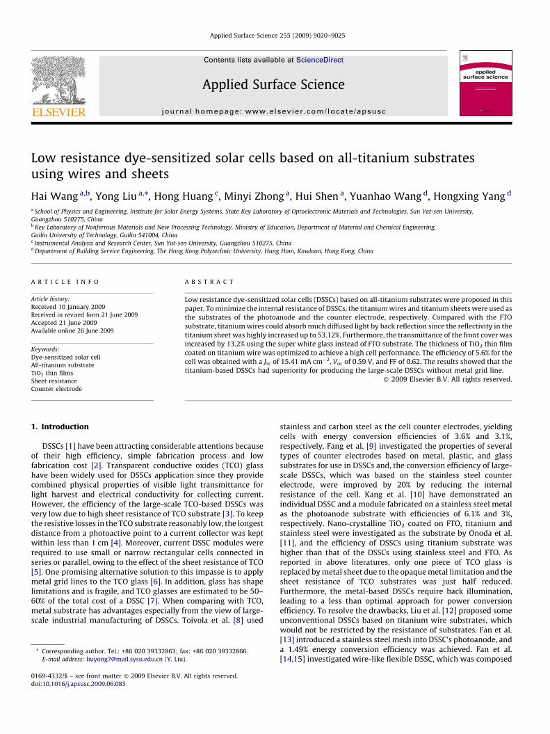
Fig. 1. Schematic of DSSCs based on all-titanium
was diluted by slow addition of water under continued grinding.Finally, a detergent (0.2 mL Triton X-100) was added.
The titanium wire, with 0.3 mm in diameter and 2.5 cm inlength, was washed in ultrasonic bath, and then coated with TiO2
film by sol–gel dip-coating process. After heat treatment at 450 8Cfor 30 min, the electrodes were immersed in a 5 � 10�4 mol/Lsolution of the ruthenium complex in dry ethanol and refluxed at80 8C for 3 h to fix dye on TiO2 electrodes, and then they werewithdrawn from the solution under a stream of dry air and storedin dry ethanol. The films with different thicknesses were obtainedby controlling the concentration of colloid.
2.3. Preparation of the counter electrode
The titanium sheet, cut into 1 cm � 2.5 cm � 0.5 cm piece, wasused as counter electrode substrate. The titanium sheet waschemically etched by low concentration HF/HNO3 solution and aresultant textured surface was obtained. Then the titanium sheetwas washed with acetone and ethanol in an ultrasonic bath for3 min.
The Pt counter electrode was coated on titanium sheet by theelectrodeposition process. Electrodeposition was carried out usingan aqueous solution of 5 � 10�3 mol/L H2PtCl6�6H2O at roomtemperature. A digital sourcemeter (Keithley, 2400) was applied asa power supply. Here, Pt electrode was prepared with 15 mA cm�2
current density for 5 s and then calcined at 150 8C for 30 min.
2.4. Assembly of cells
The structure of this cell was shown in Fig. 1. Wire-likephotoanodes were situated between the super white glass and thecounter electrode, and then they were assembled into a cell usingSurlyn as a sealant and spacer, The electrolyte, consisting of0.5 mol/L LiI, 0.05 mol/L I2, and 0.5 mol/L 4-tert-butylpyridine inacetonitrile, was also introduced. Finally, it was sealed with epoxy.Wire-like photoanodes were in parallel connection to supplyelectrons.
2.5. Measurement
A four-point probe resistivity measurement system (RTS-9,Guangzhou probe technology company, China) was used tomeasure the sheet resistance of samples. Surface morphology
substrates. (a) Front view; (b) Side view.
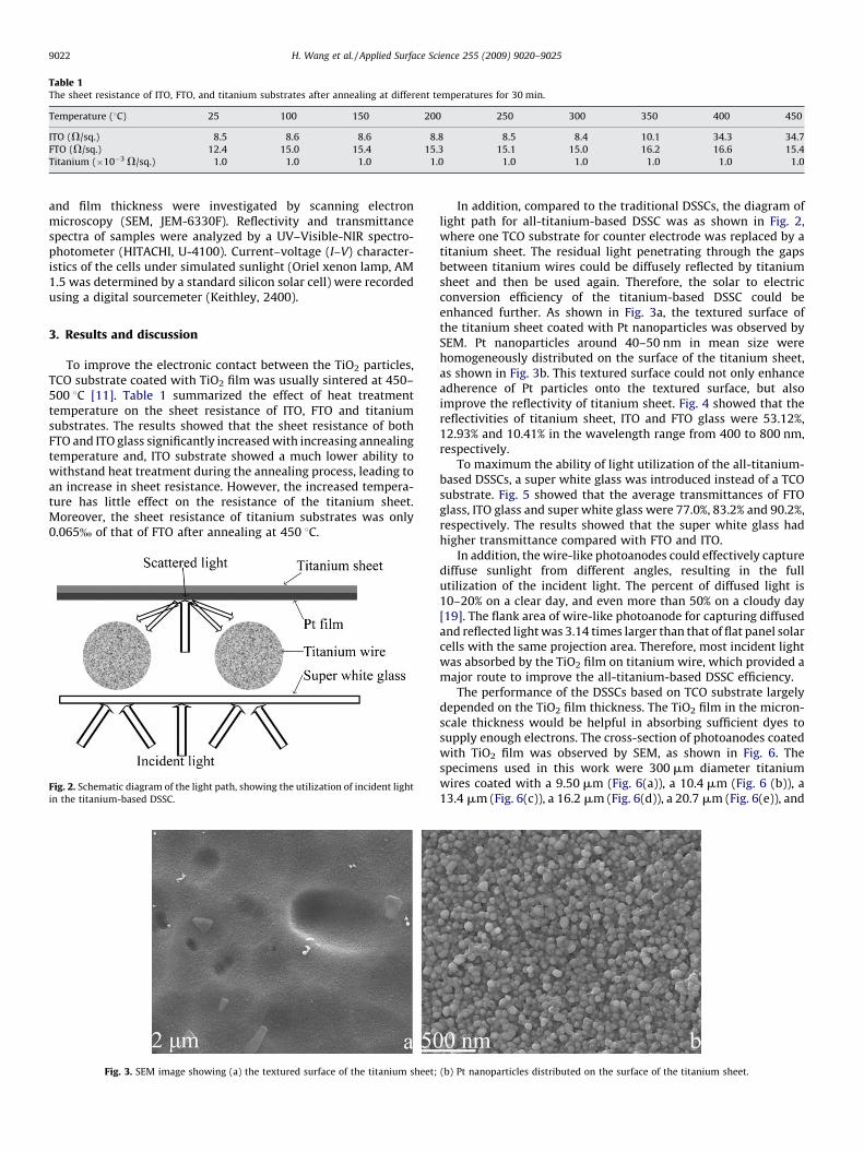
Table 1The sheet resistance of ITO, FTO, and titanium substrates after annealing at different temperatures for 30 min.
Temperature (8C) 25 100 150 200 250 300 350 400 450
ITO (V/sq.) 8.5 8.6 8.6 8.8 8.5 8.4 10.1 34.3 34.7
FTO (V/sq.) 12.4 15.0 15.4 15.3 15.1 15.0 16.2 16.6 15.4
Titanium (�10�3 V/sq.) 1.0 1.0 1.0 1.0 1.0 1.0 1.0 1.0 1.0
H. Wang et al. / Applied Surface Science 255 (2009) 9020–90259022
and film thickness were investigated by scanning electronmicroscopy (SEM, JEM-6330F). Reflectivity and transmittancespectra of samples were analyzed by a UV–Visible-NIR spectro-photometer (HITACHI, U-4100). Current–voltage (I–V) character-istics of the cells under simulated sunlight (Oriel xenon lamp, AM1.5 was determined by a standard silicon solar cell) were recordedusing a digital sourcemeter (Keithley, 2400).
3. Results and discussion
To improve the electronic contact between the TiO2 particles,TCO substrate coated with TiO2 film was usually sintered at 450–500 8C [11]. Table 1 summarized the effect of heat treatmenttemperature on the sheet resistance of ITO, FTO and titaniumsubstrates. The results showed that the sheet resistance of bothFTO and ITO glass significantly increased with increasing annealingtemperature and, ITO substrate showed a much lower ability towithstand heat treatment during the annealing process, leading toan increase in sheet resistance. However, the increased tempera-ture has little effect on the resistance of the titanium sheet.Moreover, the sheet resistance of titanium substrates was only0.065% of that of FTO after annealing at 450 8C.
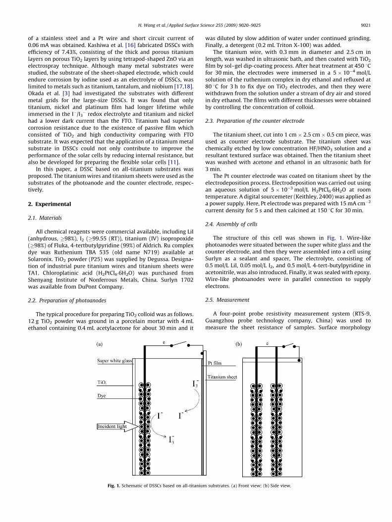
Fig. 2. Schematic diagram of the light path, showing the utilization of incident light
in the titanium-based DSSC.
Fig. 3. SEM image showing (a) the textured surface of the titanium sheet;
In addition, compared to the traditional DSSCs, the diagram oflight path for all-titanium-based DSSC was as shown in Fig. 2,where one TCO substrate for counter electrode was replaced by atitanium sheet. The residual light penetrating through the gapsbetween titanium wires could be diffusely reflected by titaniumsheet and then be used again. Therefore, the solar to electricconversion efficiency of the titanium-based DSSC could beenhanced further. As shown in Fig. 3a, the textured surface ofthe titanium sheet coated with Pt nanoparticles was observed bySEM. Pt nanoparticles around 40–50 nm in mean size werehomogeneously distributed on the surface of the titanium sheet,as shown in Fig. 3b. This textured surface could not only enhanceadherence of Pt particles onto the textured surface, but alsoimprove the reflectivity of titanium sheet. Fig. 4 showed that thereflectivities of titanium sheet, ITO and FTO glass were 53.12%,12.93% and 10.41% in the wavelength range from 400 to 800 nm,respectively.
To maximum the ability of light utilization of the all-titanium-based DSSCs, a super white glass was introduced instead of a TCOsubstrate. Fig. 5 showed that the average transmittances of FTOglass, ITO glass and super white glass were 77.0%, 83.2% and 90.2%,respectively. The results showed that the super white glass hadhigher transmittance compared with FTO and ITO.
In addition, the wire-like photoanodes could effectively capturediffuse sunlight from different angles, resulting in the fullutilization of the incident light. The percent of diffused light is10–20% on a clear day, and even more than 50% on a cloudy day[19]. The flank area of wire-like photoanode for capturing diffusedand reflected light was 3.14 times larger than that of flat panel solarcells with the same projection area. Therefore, most incident lightwas absorbed by the TiO2 film on titanium wire, which provided amajor route to improve the all-titanium-based DSSC efficiency.
The performance of the DSSCs based on TCO substrate largelydepended on the TiO2 film thickness. The TiO2 film in the micron-scale thickness would be helpful in absorbing sufficient dyes tosupply enough electrons. The cross-section of photoanodes coatedwith TiO2 film was observed by SEM, as shown in Fig. 6. Thespecimens used in this work were 300 mm diameter titaniumwires coated with a 9.50 mm (Fig. 6(a)), a 10.4 mm (Fig. 6 (b)), a13.4 mm (Fig. 6(c)), a 16.2 mm (Fig. 6(d)), a 20.7 mm (Fig. 6(e)), and
(b) Pt nanoparticles distributed on the surface of the titanium sheet.
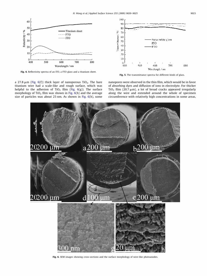
Fig. 4. Reflectivity spectra of an ITO, a FTO glass and a titanium sheet.
Fig. 5. The transmittance spectra for different kinds of glass.
H. Wang et al. / Applied Surface Science 255 (2009) 9020–9025 9023
a 27.8 mm (Fig. 6(f)) thick layer of nanoporous TiO2. The baretitanium wire had a scale-like and rough surface, which washelpful to the adhesion of TiO2 film (Fig. 6(g)). The surfacemorphology of TiO2 film was shown in Fig. 6(h) and the averagesize of particles was about 23 nm. As shown in Fig. 6(h), some
Fig. 6. SEM images showing cross-sections and the
nanopores were observed in the thin film, which would be in favorof absorbing dyes and diffusion of ions in electrolyte. For thickerTiO2 film (20.7 mm), a lot of broad cracks appeared irregularlyalong the wire and extended around the whole of specimencircumference with relatively high concentrations in some areas,
surface morphology of wire-like photoanodes.
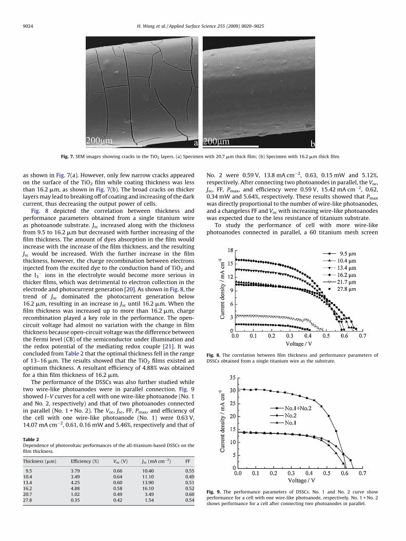
Fig. 7. SEM images showing cracks in the TiO2 layers. (a) Specimen with 20.7 mm thick film; (b) Specimen with 16.2 mm thick film.
Fig. 8. The correlation between film thickness and performance parameters of
DSSCs obtained from a single titanium wire as the substrate.
H. Wang et al. / Applied Surface Science 255 (2009) 9020–90259024
as shown in Fig. 7(a). However, only few narrow cracks appearedon the surface of the TiO2 film while coating thickness was lessthan 16.2 mm, as shown in Fig. 7(b). The broad cracks on thickerlayers may lead to breaking off of coating and increasing of the darkcurrent, thus decreasing the output power of cells.
Fig. 8 depicted the correlation between thickness andperformance parameters obtained from a single titanium wireas photoanode substrate. Jsc increased along with the thicknessfrom 9.5 to 16.2 mm but decreased with further increasing of thefilm thickness. The amount of dyes absorption in the film wouldincrease with the increase of the film thickness, and the resultingJsc would be increased. With the further increase in the filmthickness, however, the charge recombination between electronsinjected from the excited dye to the conduction band of TiO2 andthe I3
� ions in the electrolyte would become more serious inthicker films, which was detrimental to electron collection in theelectrode and photocurrent generation [20]. As shown in Fig. 8, thetrend of Jsc dominated the photocurrent generation below16.2 mm, resulting in an increase in Jsc until 16.2 mm. When thefilm thickness was increased up to more than 16.2 mm, chargerecombination played a key role in the performance. The open-circuit voltage had almost no variation with the change in filmthickness because open-circuit voltage was the difference betweenthe Fermi level (CB) of the semiconductor under illumination andthe redox potential of the mediating redox couple [21]. It wasconcluded from Table 2 that the optimal thickness fell in the rangeof 13–16 mm. The results showed that the TiO2 films existed anoptimum thickness. A resultant efficiency of 4.88% was obtainedfor a thin film thickness of 16.2 mm.
The performance of the DSSCs was also further studied whiletwo wire-like photoanodes were in parallel connection. Fig. 9showed I–V curves for a cell with one wire-like photoanode (No. 1and No. 2, respectively) and that of two photoanodes connectedin parallel (No. 1 + No. 2). The Voc, Jsc, FF, Pmax, and efficiency ofthe cell with one wire-like photoanode (No. 1) were 0.63 V,14.07 mA cm�2, 0.61, 0.16 mW and 5.46%, respectively and that of
Table 2Dependence of photovoltaic performances of the all-titanium-based DSSCs on the
film thickness.
Thickness (mm) Efficiency (%) Voc (V) Jsc (mA cm�2) FF
9.5 3.79 0.66 10.40 0.55
10.4 3.49 0.64 11.10 0.49
13.4 4.25 0.60 13.90 0.51
16.2 4.88 0.58 16.10 0.52
20.7 1.02 0.49 3.49 0.60
27.8 0.35 0.42 1.54 0.54
No. 2 were 0.59 V, 13.8 mA cm�2, 0.63, 0.15 mW and 5.12%,respectively. After connecting two photoanodes in parallel, the Voc,Jsc, FF, Pmax, and efficiency were 0.59 V, 15.42 mA cm�2, 0.62,0.34 mW and 5.64%, respectively. These results showed that Pmax
was directly proportional to the number of wire-like photoanodes,and a changeless FF and Voc with increasing wire-like photoanodeswas expected due to the less resistance of titanium substrate.
To study the performance of cell with more wire-likephotoanodes connected in parallel, a 60 titanium mesh screen
Fig. 9. The performance parameters of DSSCs. No. 1 and No. 2 curve show
performance for a cell with one wire-like photoanode, respectively. No. 1 + No. 2
shows performance for a cell after connecting two photoanodes in parallel.
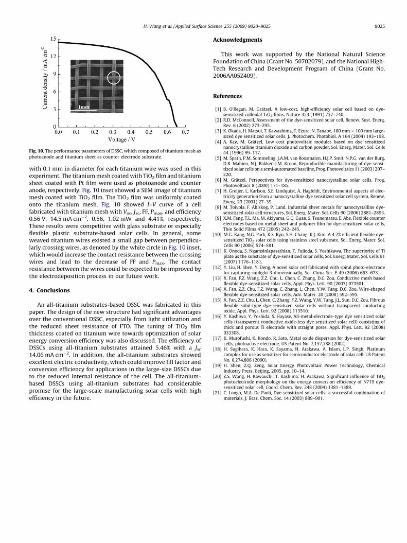
Fig. 10. The performance parameters of DSSC, which composed of titanium mesh as
photoanode and titanium sheet as counter electrode substrate.
H. Wang et al. / Applied Surface Science 255 (2009) 9020–9025 9025
with 0.1 mm in diameter for each titanium wire was used in thisexperiment. The titanium mesh coated with TiO2 film and titaniumsheet coated with Pt film were used as photoanode and counteranode, respectively. Fig. 10 inset showed a SEM image of titaniummesh coated with TiO2 film. The TiO2 film was uniformly coatedonto the titanium mesh. Fig. 10 showed I–V curve of a cellfabricated with titanium mesh with Voc, Jsc, FF, Pmax, and efficiency0.56 V, 14.5 mA cm�2, 0.56, 1.02 mW and 4.41%, respectively.These results were competitive with glass substrate or especiallyflexible plastic substrate-based solar cells. In general, someweaved titanium wires existed a small gap between perpendicu-larly crossing wires, as denoted by the white circle in Fig. 10 inset,which would increase the contact resistance between the crossingwires and lead to the decrease of FF and Pmax. The contactresistance between the wires could be expected to be improved bythe electrodeposition process in our future work.
4. Conclusions
An all-titanium substrates-based DSSC was fabricated in thispaper. The design of the new structure had significant advantagesover the conventional DSSC, especially from light utilization andthe reduced sheet resistance of FTO. The tuning of TiO2 filmthickness coated on titanium wire towards optimization of solarenergy conversion efficiency was also discussed. The efficiency ofDSSCs using all-titanium substrates attained 5.46% with a Jsc
14.06 mA cm�2. In addition, the all-titanium substrates showedexcellent electric conductivity, which could improve fill factor andconversion efficiency for applications in the large-size DSSCs dueto the reduced internal resistance of the cell. The all-titanium-based DSSCs using all-titanium substrates had considerablepromise for the large-scale manufacturing solar cells with highefficiency in the future.
Acknowledgments
This work was supported by the National Natural ScienceFoundation of China (Grant No. 50702079), and the National High-Tech Research and Development Program of China (Grant No.2006AA05Z409).
References
[1] B. O’Regan, M. Gratzel, A low-cost, high-efficiency solar cell based on dye-sensitized colloidal TiO2 films, Nature 353 (1991) 737–740.
[2] R.D. McConnell, Assessment of the dye-sensitized solar cell, Renew. Sust. Energ.Rev. 6 (2002) 273–295.
[3] K. Okada, H. Matsui, T. Kawashima, T. Ezure, N. Tanabe, 100 mm � 100 mm large-sized dye sensitized solar cells, J. Photochem. Photobiol. A 164 (2004) 193–198.
[4] A. Kay, M. Gratzel, Low cost photovoltaic modules based on dye sensitizednanocrystalline titanium dioxide and carbon powder, Sol. Energ. Mater. Sol. Cells44 (1996) 99–117.
[5] M. Spath, P.M. Sommeling, J.A.M. van Roosmalen, H.J.P. Smit, N.P.G. van der Burg,D.R. Mahieu, N.J. Bakker, J.M. Kroon, Reproducible manufacturing of dye-sensi-tized solar cells on a semi-automated baseline, Prog. Photovoltaics 11 (2003) 207–220.
[6] M. Gratzel, Perspectives for dye-sensitized nanocrystalline solar cells, Prog.Photovoltaics 8 (2000) 171–185.
[7] H. Greijer, L. Karlson, S.E. Lindquist, A. Hagfeldt, Environmental aspects of elec-tricity generation from a nanocrystalline dye sensitized solar cell system, Renew.Energ. 23 (2001) 27–39.
[8] M. Toivola, F. Ahlskog, P. Lund, Industrial sheet metals for nanocrystalline dye-sensitized solar cell structures, Sol. Energ. Mater. Sol. Cells 90 (2006) 2881–2893.
[9] X.M. Fang, T.L. Ma, M. Akiyama, G.Q. Guan, S. Tsunematsu, E. Abe, Flexible counterelectrodes based on metal sheet and polymer film for dye-sensitized solar cells,Thin Solid Films 472 (2005) 242–245.
[10] M.G. Kang, N.G. Park, K.S. Ryu, S.H. Chang, K.J. Kim, A 4.2% efficient flexible dye-sensitized TiO2 solar cells using stainless steel substrate, Sol. Energ. Mater. Sol.Cells 90 (2006) 574–581.
[11] K. Onoda, S. Ngamsinlapasathian, T. Fujieda, S. Yoshikawa, The superiority of Tiplate as the substrate of dye-sensitized solar cells, Sol. Energ. Mater. Sol. Cells 91(2007) 1176–1181.
[12] Y. Liu, H. Shen, Y. Deng, A novel solar cell fabricated with spiral photo-electrodefor capturing sunlight 3-dimensionally, Sci. China Ser. E 49 (2006) 663–673.
[13] X. Fan, F.Z. Wang, Z.Z. Chu, L. Chen, C. Zhang, D.C. Zou, Conductive mesh basedflexible dye-sensitized solar cells, Appl. Phys. Lett. 90 (2007) 073501.
[14] X. Fan, Z.Z. Chu, F.Z. Wang, C. Zhang, L. Chen, Y.W. Tang, D.C. Zou, Wire-shapedflexible dye-sensitized solar cells, Adv. Mater. 20 (2008) 592–595.
[15] X. Fan, Z.Z. Chu, L. Chen, C. Zhang, F.Z. Wang, Y.W. Tang, J.L. Sun, D.C. Zou, Fibrousflexible solid-type dye-sensitized solar cells without transparent conductingoxide, Appl. Phys. Lett. 92 (2008) 113510.
[16] Y. Kashiwa, Y. Yoshida, S. Hayase, All-metal-electrode-type dye sensitized solarcells (transparent conductive oxide-less dye sensitized solar cell) consisting ofthick and porous Ti electrode with straight pores, Appl. Phys. Lett. 92 (2008)033308.
[17] K. Murofushi, K. Kondo, R. Sato, Metal oxide dispersion for dye-sensitized solarcells, photoactive electrode, US Patent No. 7,157,788 (2002).
[18] H. Sugihara, K. Hara, K. Sayama, H. Arakawa, A. Islam, L.P. Singh, Platinumcomplex for use as sensitizer for semiconductor electrode of solar cell, US PatentNo. 6,274,806 (2000).
[19] H. Shen, Z.Q. Zeng, Solar Energy Photovoltaic Power Technology, ChemicalIndustry Press, Beijing, 2005, pp. 10–14.
[20] Z.S. Wang, H. Kawauchi, T. Kashima, H. Arakawa, Significant influence of TiO2
photoelectrode morphology on the energy conversion efficiency of N719 dye-sensitized solar cell, Coord. Chem. Rev. 248 (2004) 1381–1389.
[21] C. Longo, M.A. De Paoli, Dye-sensitized solar cells: a successful combination ofmaterials, J. Braz. Chem. Soc. 14 (2003) 889–901.