Embed Size (px)
Citation preview

AGuide toLow Resistance Measurement
Experts in what we do

Contents
02-03 Introduction
04-05 Applications
06 Resistance
06-09 Principles of Resistance Measurement
09-10 Methods of 4 Terminal Connections
10-19 Possible Measurement Errors
14-18 Choosing the Right Instrument
18-24 Application Examples
25-33 Useful Formulas and Charts
34 Find out more

Experts in what we do

The measurement of very large or very small
quantities is always difficult, and resistance
measurement is no exception. Values above 1GΩ
and values below 1Ω both present measurement
problems.
Cropico is a world leader in low resistance
measurement; we produce a comprehensive
range of low resistance ohmmeters and
accessories which cover most measurement
applications. This handbook gives an overview of
low resistance measurement techniques, explains
common causes of errors and how to avoid them.
We have also included useful tables of wire and
cable characteristics, temperature coefficients
and various formulas to ensure you make the best
possible choice when selecting your measuring
instrument and measurement technique.
We hope you will find this booklet a valuable
addition to your toolkit.
2
With resistance measurement,
precision is everything.
This guide is what we know
about achieving the highest
quality measurements possible.
3
Experts in what we do
4
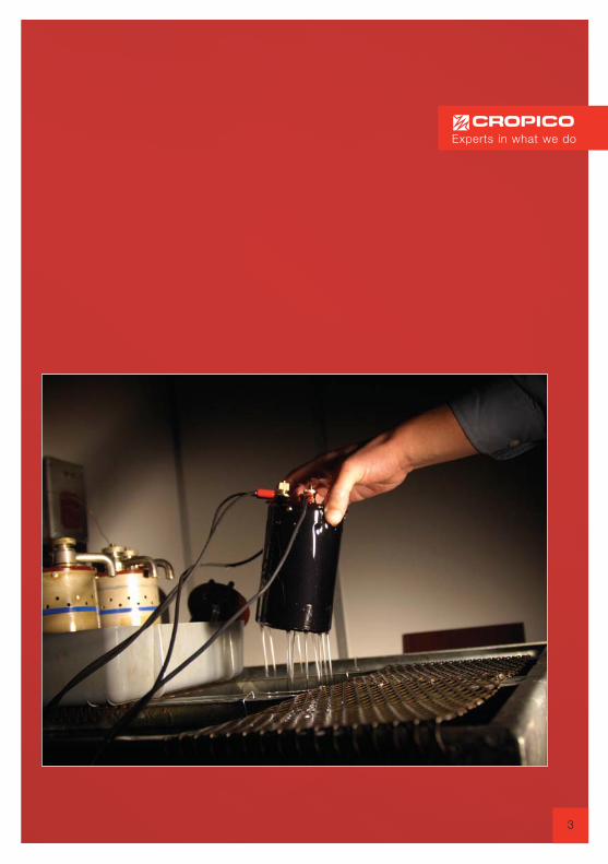
Applications
There are many reasons why the
resistance of material is measured.
Here are a few.
Manufacturers of componentsResistors, inductors and chokes all have toverify that their product meets the specifiedresistance tolerance, end of production line andquality control testing.
Manufacturers of switches,relays & connectorsVerification that the contact resistance is belowpre specified limits is required. This can beachieved at end of production line testing,ensuring quality control.
Cable manufacturersMust measure the resistance of the copperwires they produce, resistance too high meansthat the current carrying capability of the cableis reduced; resistance too low means that themanufacturer is being too generous on thecable diameter using more copper than heneeds to, which can be very expensive.
Installation & maintenance of powercables, switchgear & voltage tap changersThese require the cable joints and switchcontacts to be of the lowest possible resistance
thus avoiding the joint or contact frombecoming excessively hot, a poor cable joint orswitch contact will soon fail due to this heatingeffect. Routine preventative maintenance withregular resistance checks ensures the bestpossible life performances.
Electric motor & generator manufacturersThere is a requirement to determine themaximum temperature reached under full load.To determine this temperature, the temperaturecoefficient of the copper winding is used. Theresistance is first measured with the motor orgenerator cold i.e. at ambient temperature, theunit is then run at full load for a specified periodand the resistance measured again. From thechange in resistance value, the internalmotor/generator temperature can bedetermined. Our ohmmeters are also used tomeasure the individual coils of a motor winding,to ensure there are no short or open circuitturns and that each coil is balanced.
The automotive industryRequirement to measure the resistance of robotwelding cables to ensure that the weld quality
5
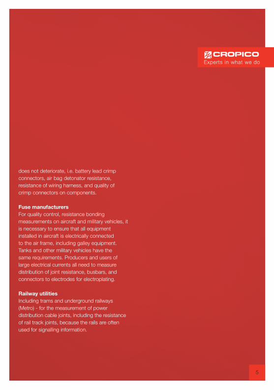
does not deteriorate, i.e. battery lead crimpconnectors, air bag detonator resistance,resistance of wiring harness, and quality ofcrimp connectors on components.
Fuse manufacturersFor quality control, resistance bondingmeasurements on aircraft and military vehicles, itis necessary to ensure that all equipmentinstalled in aircraft is electrically connectedto the air frame, including galley equipment.Tanks and other military vehicles have thesame requirements. Producers and users oflarge electrical currents all need to measuredistribution of joint resistance, busbars, andconnectors to electrodes for electroplating.
Railway utilitiesIncluding trams and underground railways(Metro) - for the measurement of powerdistribution cable joints, including the resistanceof rail track joints, because the rails are oftenused for signalling information.
Experts in what we do

6
There exists a variety of resistance measuringinstruments that will calculate and display theresistance reading without the need forcalculations by the user. These measuringinstruments will employ either a two wire or afour wire measurement technique.
Kelvin Double BridgeThe Kelvin Bridge is a variation of theWheatstone bridge which enables lowresistances to be measured. Themeasurement range would typically be 1mΩto 1kΩ with the smallest resolution of 1µΩ.The limitations of the Kelvin bridge are:-
1. requires manual balancing2. sensitive null detector or galvanometer is
required to detect balance condition3. measurement current needs to be
reasonably high to achieve sufficient sensitivity
The Kelvin Double Bridge has generally beenreplaced by digital ohmmeters.
DMM - Two-wire ConnectionA simple digital multimeter can be used for
R
V
Current I
Where:
I = Electrical Current (Amperes)V = Voltage (Voltage)R = Resistance (Ohms)
RESISTANCE
Ohm’s Law V = I x R (Volts = Current xResistance). The Ohm (Ω) is a unit of electricalresistance equal to that of a conductor in which acurrent of one ampere is produced by a potential ofone volt across its terminals.Ohm's law, named after its discoverer the Germanphysicist Georg Ohm, is one of the most important,basic laws of electricity. It defines the relationshipbetween the three fundamental electrical quantities:current, voltage and resistance. When a voltage isapplied to a circuit containing only resistiveelements, current flows according to Ohm's Law,which is shown below.
PRINCIPLES OF RESISTANCEMEASUREMENT
Ammeter Voltmeter method This method goes right back to basics. If we usea battery as our voltage source, a voltmeter tomeasure the voltage and an ammeter to measurethe current in the circuit, we can calculate theresistance with reasonable accuracy.Whilst this method can provide goodmeasurement results, it is not a practicalsolution to everyday measurement needs.
Resistance
Volt Amp
Resistance = VoltCurrent
7
higher values of resistance. They employ the 2wire method of measurement and are onlysuitable for measuring values above 100Ω andwhere high accuracy is not required.
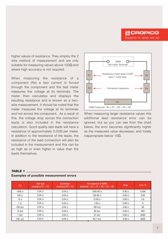
When measuring the resistance of acomponent (Rx) a test current is forcedthrough the component and the test metermeasures the voltage at its terminals. Themeter then calculates and displays theresulting resistance and is known as a two-wire measurement. It should be noted that themeter measures the voltage at its terminalsand not across the component. As a result ofthis, the voltage drop across the connectionleads is also included in the resistancecalculation. Good quality test leads will have aresistance of approximately 0.02Ω per meter.In addition to the resistance of the leads, theresistance of the lead connection will also beincluded in the measurement and this can beas high as or even higher in value than theleads themselves.
When measuring larger resistance values thisadditional lead resistance error can beignored, but as you can see from the chartbelow, the error becomes significantly higheras the measured value decreases, and totallyinappropriate below 10Ω.
Digital ohmmeters – 4 wire connection
R1
R3
R2
R4
RX
DMM measures:- Rx + R1 + R2 + R3 + R4
Resistance of test leads 0.02 each 1 metre lead
Connection resistance
DMMTest meter Terminals
Test lead resistance R1 + R2RX
Connectionresistance R3 + R4
Rx measured at DMMterminals = Rx + R1 + R2 + R3 + R4 Error Error %
1000 Ω100 Ω10 Ω1 Ω
100 mΩ10 mΩ1 mΩ
100 µΩ
0.04 Ω0.04 Ω0.04 Ω0.04 Ω0.04 Ω0.04 Ω0.04 Ω0.04 Ω
0.04 Ω0.04 Ω0.04 Ω0.04 Ω0.04 Ω0.04 Ω0.04 Ω0.04 Ω
1000.08 Ω100.08 Ω10.08 Ω1.08 Ω
180 mΩ90 mΩ81 mΩ
80.1 mΩ
0.08 Ω0.08 Ω0.08 Ω0.08 Ω0.08 Ω0.08 Ω0.08 Ω0.08 Ω
0.008
0.08
0.8
8
80
800
8000
8000
TABLE 1Examples of possible measurement errors
Experts in what we do
8
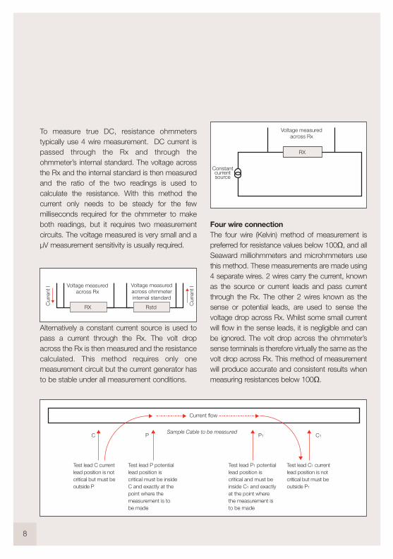
Four wire connectionThe four wire (Kelvin) method of measurement ispreferred for resistance values below 100Ω, and allSeaward milliohmmeters and microhmmeters usethis method. These measurements are made using4 separate wires. 2 wires carry the current, knownas the source or current leads and pass currentthrough the Rx. The other 2 wires known as thesense or potential leads, are used to sense thevoltage drop across Rx. Whilst some small currentwill flow in the sense leads, it is negligible and canbe ignored. The volt drop across the ohmmeter’ssense terminals is therefore virtually the same as thevolt drop across Rx. This method of measurementwill produce accurate and consistent results whenmeasuring resistances below 100Ω.
To measure true DC, resistance ohmmeterstypically use 4 wire measurement. DC current ispassed through the Rx and through theohmmeter’s internal standard. The voltage acrossthe Rx and the internal standard is then measuredand the ratio of the two readings is used tocalculate the resistance. With this method thecurrent only needs to be steady for the fewmilliseconds required for the ohmmeter to makeboth readings, but it requires two measurementcircuits. The voltage measured is very small and aµV measurement sensitivity is usually required.
Alternatively a constant current source is used topass a current through the Rx. The volt dropacross the Rx is then measured and the resistancecalculated. This method requires only onemeasurement circuit but the current generator hasto be stable under all measurement conditions.
Cur
rent
I
Cur
rent
I
RX Rstd
Voltage measuredacross Rx
Voltage measuredacross ohmmeterinternal standard
RX
Constantcurrentsource
Voltage measuredacross Rx
Current flow
C P C1P1
Test lead C current lead position is not critical but must be outside P
Test lead C1 current lead position is not critical but must be outside P1
Test lead P potential lead position is critical must be inside C and exactly at the point where the measurement is to be made
Test lead P1 potential lead position is critical and must be inside C1 and exactly at the point where the measurement is to be made
Sample Cable to be measured
9
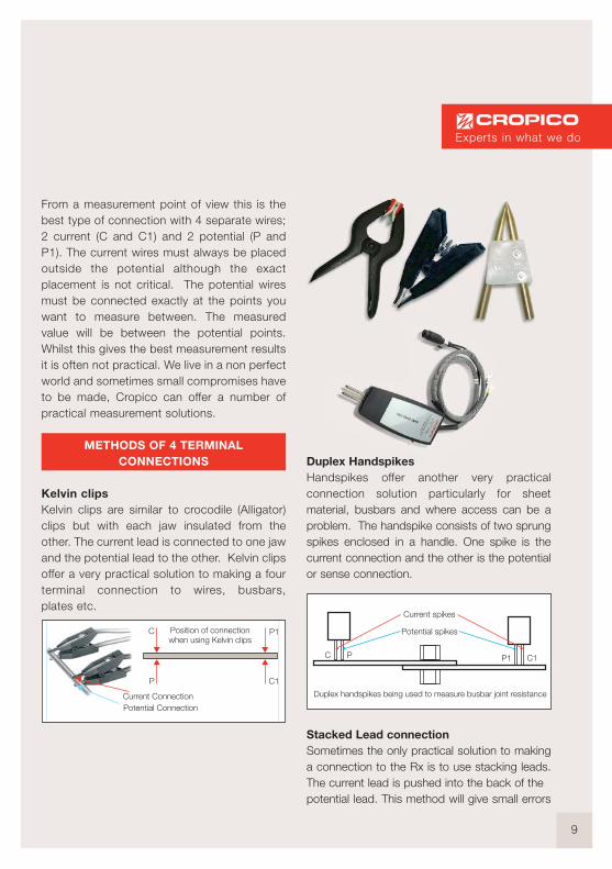
From a measurement point of view this is thebest type of connection with 4 separate wires;2 current (C and C1) and 2 potential (P andP1). The current wires must always be placedoutside the potential although the exactplacement is not critical. The potential wiresmust be connected exactly at the points youwant to measure between. The measuredvalue will be between the potential points.Whilst this gives the best measurement resultsit is often not practical. We live in a non perfectworld and sometimes small compromises haveto be made, Cropico can offer a number ofpractical measurement solutions.
METHODS OF 4 TERMINALCONNECTIONS
Kelvin clipsKelvin clips are similar to crocodile (Alligator)clips but with each jaw insulated from theother. The current lead is connected to one jawand the potential lead to the other. Kelvin clipsoffer a very practical solution to making a fourterminal connection to wires, busbars,plates etc.
C
P C1
P1Position of connectionwhen using Kelvin clips
Current ConnectionPotential Connection
Duplex Handspikes Handspikes offer another very practicalconnection solution particularly for sheetmaterial, busbars and where access can be aproblem. The handspike consists of two sprungspikes enclosed in a handle. One spike is thecurrent connection and the other is the potentialor sense connection.
Stacked Lead connectionSometimes the only practical solution to makinga connection to the Rx is to use stacking leads.The current lead is pushed into the back of the potential lead. This method will give small errors
Current spikes
Potential spikes
C1P1C P
Duplex handspikes being used to measure busbar joint resistance
Experts in what we do

because the measurement point will be wherethe potential lead connects to the current lead.For measurement of awkward-to-reach samples,this can be the best compromise solution.
Cable clamps
When measuring cables during manufacture,and for quality control purposes, it is necessaryto maintain consistent measuring conditions. Thelength of the cable sample is normally 1 metreand to ensure that accurate 1 metre lengths aremeasured, a cable clamp should be used.Cropico offer a variety of cable clamps which willaccommodate most cable sizes. The cable to bemeasured is placed in the clamp and the ends ofthe cable are clamped in the current terminals.The potential connection points are normally inthe form of knife edge contacts which are exactly1 metre apart.
10
C
P
C1
P2
Measurementpoint
Potential lead P Potential
lead CPosition of connections
when using stacked leads measurement between
Current clamp connections distance not criticalPotential knife edge
connections 1 metre apart
Jigs and fixturesWhen measuring other components such asresistors, fuses, switch contacts, rivets etc. theimportance of using a test jig to hold thecomponent cannot be emphasised enough. Thiswill ensure that the measurement conditions, i.e.position of measurement leads, are the same foreach component which will result in consistent,reliable and meaningful measurements. Jigsoften have to be specially designed to suit theapplication.
POSSIBLE MEASUREMENT ERRORS
There are several possible sources ofmeasurement error associated with lowresistance measurements. The most commonones are described below.
Dirty connectionsAs with all measurements, it is important to ensurethat the device you are connecting is clean and freefrom oxides and dirt. High resistance connectionswill cause reading errors and may preventmeasurements. It should also be noted that somecoatings and oxides on materials are goodinsulators. Anodising has a very high resistance andis a classic example. Be sure to clean off the coatingat the connection points. Cropico ohmmetersincorporate a lead error warning which will indicateif the connections are too high in resistance.
Resistance of leads too highWhilst in theory the four terminal method ofmeasurement is unaffected by lead length, caremust be taken to ensure that the leads are not toohigh in resistance. The potential leads are not critical
11
and can usually be up to 1kΩ without affecting themeasurement accuracy, but the current leads arecritical. If the current leads are too high in resistancethen the voltage drop across them will result ininsufficient voltage across the DUT (Device UnderTest) to make a sensible reading. Cropicoohmmeters check this compliance voltage acrossthe DUT and prevent a measurement from beingmade if it falls too low. A warning display is alsoprovided; preventing the reading, ensuring that falsemeasurements are not carried out. If you need touse long measuring leads, then increase thediameter of the cables to reduce their resistance.
Measurement NoiseAs with any type of low voltage measurement, noisecan be a problem. Noise is created within test leadswhen they are in the influence of a magnetic fieldwhich is changing or the leads are moving withinthat field. To minimise this effect, leads should bekept as short as is practical, kept still and ideallyshielded. Cropico realises that there are manypractical constraints on achieving this ideal, andhave therefore designed the circuits within theirohmmeters to minimise and eliminate these effects.
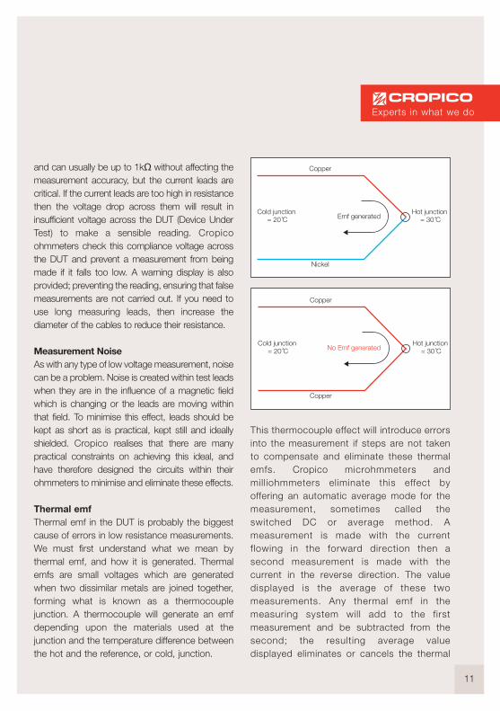
Thermal emfThermal emf in the DUT is probably the biggestcause of errors in low resistance measurements. We must first understand what we mean bythermal emf, and how it is generated. Thermalemfs are small voltages which are generatedwhen two dissimilar metals are joined together,forming what is known as a thermocouplejunction. A thermocouple will generate an emfdepending upon the materials used at thejunction and the temperature difference betweenthe hot and the reference, or cold, junction.
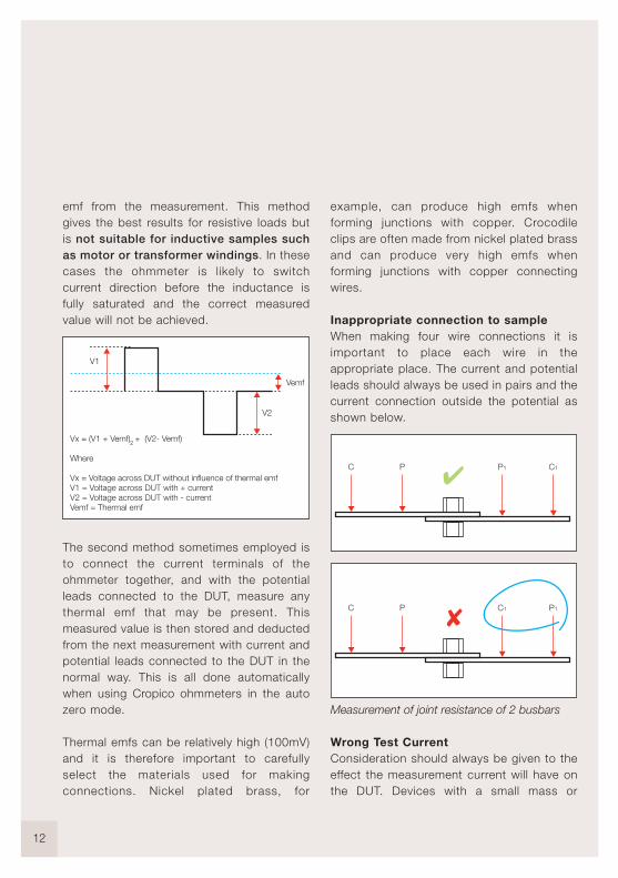
This thermocouple effect will introduce errorsinto the measurement if steps are not takento compensate and eliminate these thermalemfs. Cropico microhmmeters andmilliohmmeters eliminate this effect byoffering an automatic average mode for themeasurement, sometimes called theswitched DC or average method. Ameasurement is made with the currentflowing in the forward direction then asecond measurement is made with thecurrent in the reverse direction. The valuedisplayed is the average of these twomeasurements. Any thermal emf in themeasuring system will add to the firstmeasurement and be subtracted from thesecond; the resulting average valuedisplayed eliminates or cancels the thermal
Copper
Nickel
Emf generatedCold junction
= 20 CHot junction
= 30 C
Copper
Copper
No Emf generatedCold junction
= 20 CHot junction
= 30 C
Experts in what we do
12
emf from the measurement. This methodgives the best results for resistive loads butis not suitable for inductive samples suchas motor or transformer windings. In thesecases the ohmmeter is likely to switchcurrent direction before the inductance isfully saturated and the correct measuredvalue will not be achieved.
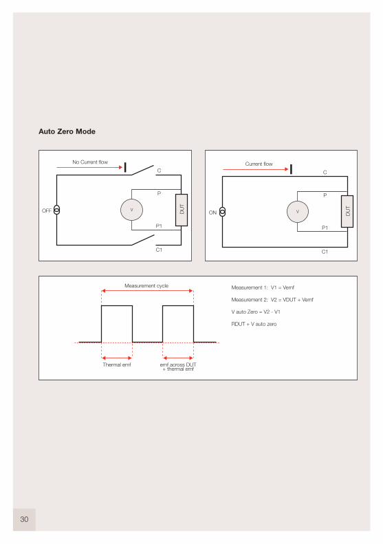
The second method sometimes employed isto connect the current terminals of theohmmeter together, and with the potentialleads connected to the DUT, measure anythermal emf that may be present. Thismeasured value is then stored and deductedfrom the next measurement with current andpotential leads connected to the DUT in thenormal way. This is all done automaticallywhen using Cropico ohmmeters in the autozero mode.
Thermal emfs can be relatively high (100mV)and it is therefore important to carefullyselect the materials used for makingconnections. Nickel plated brass, for
example, can produce high emfs whenforming junctions with copper. Crocodileclips are often made from nickel plated brassand can produce very high emfs whenforming junctions with copper connectingwires.
Inappropriate connection to sampleWhen making four wire connections it isimportant to place each wire in theappropriate place. The current and potentialleads should always be used in pairs and thecurrent connection outside the potential asshown below.
Measurement of joint resistance of 2 busbars
Wrong Test CurrentConsideration should always be given to theeffect the measurement current will have onthe DUT. Devices with a small mass or
V1
V2
Vemf
Vx = (V1 + Vemf) + (V2- Vemf)
Where
Vx = Voltage across DUT without influence of thermal emfV1 = Voltage across DUT with + currentV2 = Voltage across DUT with - currentVemf = Thermal emf
2
C P P1 C1
C P C1 P1

13
The Temperature Coefficient of Copper (nearroom temperature) is +0.393 % per
oC. This
means if the temperature increases 1oC the
resistance will increase 0.393%. Aluminiumis +0.4100 % per
oC.
constructed with materials that have a hightemperature coefficient, such as thin strandsof copper wire, will need to be measuredwith the minimum current available to avoidheating. In these cases a single pulse ofcurrent may be appropriate to cause the veryminimum of heating. Should the DUT besubject to the influences of thermal emf thenthe switched current method describedearlier is appropriate. The Cropico DO5000series of ohmmeters have selectablecurrents from 10% to 100% in 1% steps,plus a single pulse mode and consequentlymay be configured to suit most applications.
Temperature influencesIt is important to be aware that the resistanceof most materials will be affected by theirtemperature. It may be necessary, dependingupon the accuracy of measurement required,to control the environment in which themeasurement is made, thus keeping theambient temperature constant. This wouldbe the case when measuring resistancereference standards which are measured in acontrolled laboratory at either 20
oC or 23
oC.
For measurements where controlling theambient temperature is not possible, the ATC(automatic temperature compensation)facility can be used. A temperature probe,connected to the ohmmeter, senses theambient temperature and the resistancereading is corrected to a referencetemperature of 20
oC. Two of the most
common materials measured are copper andaluminium and their temperature coefficientsare illustrated opposite.
20 C 30 CTemperature
0.1
105
Res
ista
nce
Aluminium = 4100 ppm/ C
Copper = 3930 ppm/ C
Experts in what we do

14
closeness of the agreement between the result ofa measured value and the true value. It isnormally expressed in two parts i.e. a percentage of reading plus a percentage full scale. Theaccuracy statement should include thetemperature range applicable, plus the length oftime the accuracy will remain within the indicatedlimits. Warning: some manufacturers give a veryhigh accuracy statement but this is valid only fora short period of 30 or 90 Days. All Cropicoohmmeters specify accuracy for a full 1 year.
Resolution is the smallest increment that themeasuring instrument will display. It should benoted that to achieve high measurementaccuracy a suitably high resolution is needed, buta high resolution in itself does not indicate thatthe measurement has a high accuracy.
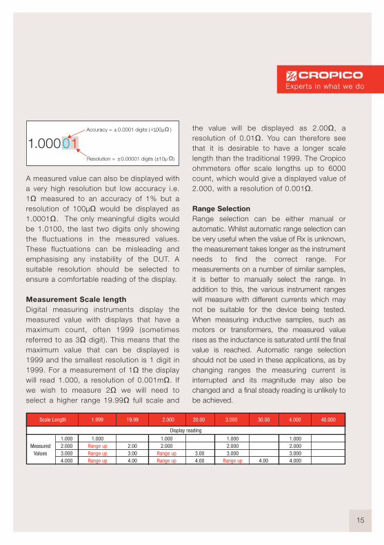
Example: To measure 1Ω with an accuracy of0.01% (± 0.0001) requires the measurement tobe displayed with a minimum resolution of100µΩ (1.0001ohms).
CHOOSING THE RIGHT INSTRUMENT
TABLE 2Typical Instrument specification chart
Range:The maximum reading possible at that setting
Resolution:The smallest number (digit) displayed for thatrange
Measurement Current:The nominal current used by that range
Accuracy:Uncertainty of the measurement over theambient temperature range 15 to 25
oC
Temperature Coefficient:The additional possible error below ambienttemperature of 15
oC and above 25
oC
When selecting the best instrument for yourapplication the following should be taken intoconsideration:-
Accuracy can be better described as theuncertainty of measurement, which is the
ResolutionRange Measurement Current Accuracy @ 20 oC ±5 oC, 1 year Temperature Coefficient / oC
60 Ω6 Ω
600 m Ω60 m Ω6 m Ω
600 µ Ω
10 m Ω1 m Ω
100 µ Ω10 µ Ω1 µ Ω
0.1 µ Ω
1 mA
10 mA
100 mA
1 A
10 A
10 A
±(0.15% Rdg + 0.05% FS)
±(0.15% Rdg + 0.05% FS)
±(0.15% Rdg + 0.05% FS)
±(0.15% Rdg + 0.05% FS)
±(0.2% Rdg + 0.01% FS)
±(0.2% Rdg + 0.02% FS)
40 ppm Rdg + 30 ppm FS
40 ppm Rdg + 30 ppm FS
40 ppm Rdg + 30 ppm FS
40 ppm Rdg + 30 ppm FS
40 ppm Rdg + 30 ppm FS
40 ppm Rdg + 250 ppm FS
15
A measured value can also be displayed witha very high resolution but low accuracy i.e.1Ω measured to an accuracy of 1% but aresolution of 100µΩ would be displayed as1.0001Ω. The only meaningful digits wouldbe 1.0100, the last two digits only showingthe fluctuations in the measured values.These fluctuations can be misleading andemphasising any instability of the DUT. Asuitable resolution should be selected toensure a comfortable reading of the display.
Measurement Scale length Digital measuring instruments display themeasured value with displays that have amaximum count, often 1999 (sometimesreferred to as 3Ω digit). This means that themaximum value that can be displayed is1999 and the smallest resolution is 1 digit in1999. For a measurement of 1Ω the displaywill read 1.000, a resolution of 0.001mΩ. Ifwe wish to measure 2Ω we will need toselect a higher range 19.99Ω full scale and
the value will be displayed as 2.00Ω, aresolution of 0.01Ω. You can therefore seethat it is desirable to have a longer scalelength than the traditional 1999. The Cropicoohmmeters offer scale lengths up to 6000count, which would give a displayed value of2.000, with a resolution of 0.001Ω.
Range SelectionRange selection can be either manual orautomatic. Whilst automatic range selection canbe very useful when the value of Rx is unknown,the measurement takes longer as the instrumentneeds to find the correct range. Formeasurements on a number of similar samples,it is better to manually select the range. Inaddition to this, the various instrument rangeswill measure with different currents which maynot be suitable for the device being tested.When measuring inductive samples, such asmotors or transformers, the measured valuerises as the inductance is saturated until the finalvalue is reached. Automatic range selectionshould not be used in these applications, as bychanging ranges the measuring current isinterrupted and its magnitude may also bechanged and a final steady reading is unlikely tobe achieved.
Resolution = 0.00001 digits ( 10µ )
Accuracy = 0.0001 digits ( 100µ )
1.999Scale Length
1.000Range upRange upRange up
19.99 2.000 20.00 3.000 30.00 4.000 40.000
2.003.004.00
1.0002.000
Range upRange up
3.004.00
1.0002.0003.000
Range up 4.00
1.0002.0003.0004.000
1.0002.0003.0004.000
MeasuredValues
Display reading
Experts in what we do
16
Temperature coefficient The temperature coefficient of a measuringinstrument is important as it can significantlyaffect the accuracy of the measurement.Measuring instruments are normally calibrated inan ambient temperature of 20 or 23 OC. Thetemperature coefficient states how themeasured accuracy is affected due to variationsin ambient temperature.
Current Magnitude and Mode Selecting an instrument with the appropriatemeasuring current for the application isimportant. For example, if thin wires are to bemeasured, then a high measuring current wouldheat the wire and change its resistance value.Copper wire has a temperature coefficient of 4%per OC at ambient temperatures, so for a wirewith a 1Ω resistance, raising the temperature by10 OC will increase its value to 10 x 0.004 =0.04Ω. Some applications, however, benefitfrom higher currents.
The measurement current mode can also beimportant. Again, when measuring thin wires, ashort measurement pulse of current rather thanusing a continuous current, will minimise anyheating effect. A switched DC measuring modemay also be appropriate to eliminate thermalemf errors, but for measuring motor windings ortransformers, a current pulse or switched DCwould be inappropriate. Continuous current isrequired to saturate inductance giving thecorrect measured value.
Automatic Temperature Compensation When measuring materials with a high
temperature coefficient, such as copper, theresistance value will increase withtemperature. Measurements taken at anambient temperature of 20
oC will be 0.4%
lower than measurements at 30 oC. This can
be misleading when trying to compare thevalues for quality control purposes. Toovercome this, some ohmmeters are providedwith automatic temperature compensation(ATC). The ambient temperature is measuredwith a temperature sensor, and the resistancevalue displayed is corrected for temperaturechanges referencing the readings to 20
oC.
Measurement speed The speed of measurement is not normally tooimportant and most ohmmeters will measure atapproximately 1 reading per second, but inautomated processes such as componentselection and production line testing, fastmeasuring speeds, up to 50 measurements persecond, can be desirable. Of course whenmeasuring at these speeds the ohmmeter needsto be remotely controlled using a computer orPLC interfaces.
Remote connections For remote connection IEEE-488, RS232 or PLCinterface may be appropriate. The IEEE-488interface is a parallel port for the transmission of8 bits (1byte) of information at a time over 8wires. It has a transmission speed greater thanRS232 but is limited in connection cabledistance to 20 metres.
The RS232 interface is a serial port fortransmission of data in serial bit format. RS232

17
has a slower transmission speed than IEEE-488and requires only 3 lines to transmit data,receive data and signal ground.
The PLC interface allows basic remote controlof the microhmmeter by a Programmable LogicController or similar device.
EnvironmentalConsideration should be given to the type ofenvironment in which the ohmmeter is to beused. Is a portable unit needed? Does theconstruction need to be rugged enough towithstand building site conditions? Whattemperature and humidity range does it need tooperate in?
Verification and calibration Accuracy verification is the confirmation that theinstrument is within its published specificationand no adjustment is made. This isaccomplished by connecting resistancestandards to the ohmmeter and confirming thatthe instrument measured and displayed valuesare the same as the standard’s certified value. Calibration is the adjustment of the instrumentso that the measured and displayed value is thesame as the certified standards value. TheCropico range of ohmmeters stores thecalibration data and applies correctionsautomatically to each displayed value. Theadvantage of this digital calibration is thatthere are no mechanical trimmers to adjust,
TABLEOhmmeter selection chart
DO4ADO4000 DO5000 DO6 DO7 DO7e DO7010 DO8000
Manufacturers of vehicles and components - motors, alternators,connectors, cable harnesses, switches
Bonding resistance (metallization) of aircraft frames and all equipment
Calibration standards
Measurement of motor, generator and transformer resistance
Army, Navy, Air force, bonding resistance of vehicles and equipment. Calibration of equipment
Resistance measurement of components, switches, connectors, crimp joints, fuses etc
Measurement of power cable joints, underground and pylon.Measurement of earthing resistance and contactor resistancein substations
Automotive
Aerospace
Cable
Calibration Labs
Drivers and electrical machines
Distribution Catalogues
Military
Manufacturing
Utilities electrical Gas and Water
Ohmmeter �
Measurement of cable resistance
DO7 Plus
■
■
■
■
■
■
■
■
■
■
■
■
■
■
■
■
■
■
■
■
■
■
■
■
■
■
■
■
■
■
■
■
■
■
■
■
■
■
■
■
■
Series Series
Experts in what we do

18
When measuring four terminal resistors andstandards it is important that a true four terminalmeasurement is made. The current and potentialmeasuring leads must be connected to thecorresponding terminals on the resistor. Crossingover the current and potential leads will result inan incorrect measurement. Measurementsmade using the two terminal method, either byconnecting to a single pair of terminals or byconnecting the source and sense terminalstogether, will also produce incorrect results.
Rstd
P
C
P1
C1
101.00 m DMM 2terminal measurement
Using a two terminal DMM measurement on a four terminal standard will give large errors
and no need to open the instrument as alladjustments are made from the front panel.The calibration data is protected by apassword to avoid unauthorised adjustment.For each measurement range the zero andnear full scale values are adjusted. TheCropico MTS range of milliohmmetercalibration standards have all the values,including a true 4 terminal zero, housed inone convenient unit. It is important to keepgood records of verification and adjustmentdata so that any long term drifts or problemscan be identified.
APPLICATION EXAMPLES
The applications for resistance measuringinstruments are very wide ranging. Describedbelow are a few of the more common ones.
Measuring four terminal resistors and standards
A four terminal resistance standard isconstructed with 2 current terminals connectedto the ends of the resistance element and 2potential points connected at the adjusted valueof the standard. This method of constructionensures repeatable values to be achieved whenconnecting to the standard’s terminals.
Potential terminals P and P1
Resistance element
Current terminals C and C1
Rstd
P
C
P1
C1

19
International standards that may apply. It is,however, very important to the manufacturer thatthe maximum permitted resistance is achieved.From the manufacturer’s point of view the lower theresistance value per metre, the larger the diameterof the cable, and hence the greater amount ofcopper is used. Copper is expensive and is themain contributor to the cable cost, the less copperused the higher the manufacturer’s profit.
Accurate and reliable resistance measurementenables the cable manufacturer to achieve theminimum cable diameter, whilst remaining withinthe declared specification. This is a very powerfulargument for good resistance measurements in thecable industry. The accepted method of measuringmetre lengths is to use a 1 metre cable clamp.
MethodTo ensure meaningful measurements it is necessaryto define the measurement conditions. The lengthof the cable to be measured, the current used tomeasure the cable and the temperature at whichthe cable will be measured, all need to be defined.
Cable LengthIt is normal practice to measure a metre length ofcable and special cable clamps are available forholding the wire. The clamp should includeconnections for both the current and potentialpoints. The use of a cable clamp eliminatesinconsistent readings due to small changes in thelength of cable measured. Care should be taken notto stretch the wire when placing it in the clamp, asthis will increase the resistance. The clamp shouldhave provision for shielding the wire againstdraughts which can cause temperature variations.An additional desirable feature of the clamp is the
Wires and cablesDuring the production process it is necessary tomeasure the resistance of all electrical wires andcables that are used to distribute power e.g. cableused to wire a house. The resistance needs to below enough to ensure that the cables will not heatup too much when the maximum rated current isflowing. The higher the resistance, the hotter thecable will become with a set current flowingthrough it.
Cable manufacturers must ensure that theresistance per metre of the cable conforms to thepublished specification and to any National or
Rstd
P
C
P1
C1
101.00 m
Ohmmeter 4 terminalmeasurements
Four terminal measurements with Ohmmeter current and potential leads crossed will give errors
P P1
C C1
Rstd
P
C
P1
C1
101.00 m
Ohmmeter 4 terminalmeasurements
Current and potential leads correctly connected for accurate four terminal measurements
P P1
C C1
Experts in what we do
20
(Automatic Temperature Compensation). Thistemperature compensation operates bymeasuring the ambient temperature andautomatically correcting the measurement usingthe material’s temperature coefficient to calculateand display the resistance reading referenced to20
oC. By using this method all measured values
are relative to the same ambient temperature. Tominimise the heating effect of the measuringcurrent is not quite so easy. Ideally the cableshould be immersed in a tank of water which iskept at a constant temperature. The water willthen dissipate any heat in the cable and keep it ata constant temperature. However this method isexpensive, messy, and time consuming and isnormally only used for the larger cable diameters.Another solution is to limit the measuring currentand the time it is applied, thus keeping the heatingeffect to a minimum. The Cropico DO5000microhmmeter is ideally suited to this applicationas it has the ability to vary the measurementcurrent and reduce the measurement time to asingle shot measurement of approx. 0.5 secondsor in FAST MODE to 0.02 seconds.
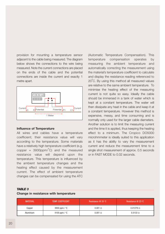
provision for mounting a temperature sensoradjacent to the cable being measured. The diagrambelow shows the connections to the wire beingmeasured. Note the current connections are placedon the ends of the cable and the potentialconnections are inside the current and exactly 1metre apart.
Influence of TemperatureAll wires and cables have a temperaturecoefficient; their resistance value will varyaccording to the temperature. Some materialshave a relatively high temperature coefficient (e.g.copper = 3930ppm/
oC) and the measured
resistance value will depend upon thetemperature. This temperature is influenced bythe ambient temperature changes and theheating effect caused by the measurementcurrent. The effect of ambient temperaturechanges can be compensated for using the ATC
MATERIAL TEMP. COEFFICIENT Resistance @ 20 oC Resistance @ 23 oC
Copper
Aluminium
3930 ppm / oC
4100 ppm / oC
0.001 Ω0.001 Ω
0.01279 Ω0.0133 Ω
128.50 m
CurrentPotential
CurrentPotentialPC P1 C1
1 Meter
TABLE 3Change in resistance with temperature

21
complete with temperature controlled waterbath. Cable clamps are available for all cablesizes, and when used with the DO5000microhmmeter, make the perfect measurementsolution.
Temperature rise of motors and transformersAll machines produce heat when operating dueto internal power losses. It is generallyimpractical to measure this heat rise withthermocouples or other temperature sensors.The winding construction is normally of copper,which has a known temperature coefficient. Bymeasuring the change in resistance of thewinding, the temperature rise can be calculated.
MethodThe winding is first measured with the machine atthe ambient temperature and the resistancevalue Rcold noted. The machine is then run atfull load for a specified period to allow thetemperature to stabilise. The unit is switched off,and in the case of motors and generators,
Possible Causes of Error1. Inconsistent measurement conditions. Proper
cable clamp not used. Position of potential measurement connections vary.
2. Ambient temperature variations not compensated for, measurement varying due tochanges in temperature.
3. Draughts blowing across cable sample causing small changes to cable temperature.
4. Cable being heated by the measuring currentcausing a continual drift in measurement.
5. Poorly made connections, oxides or dirt on cable producing high resistance at connectionpoints.
6. Plastic coating on cable retains heat in cable.
Measurement solutions
The Cropico DO5000 microhmmeter is the idealinstrument for cable testing; it has the automatictemperature compensation required with theflexibility to set both the cable material’s exacttemperature coefficient and the temperaturewhich the measurements are referenced to. Inaddition the DO5000 can operate with acontinuous measurement current or a singlecurrent pulse. Switched DC measurement modecan also be set.
To ensure that the measurement referenceconditions are consistent, Cropico offer a varietyof 1 metre cable clamps including one model
Experts in what we do
22
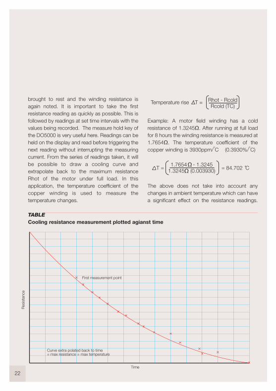
brought to rest and the winding resistance isagain noted. It is important to take the firstresistance reading as quickly as possible. This isfollowed by readings at set time intervals with thevalues being recorded. The measure hold key ofthe DO5000 is very useful here. Readings can beheld on the display and read before triggering thenext reading without interrupting the measuringcurrent. From the series of readings taken, it willbe possible to draw a cooling curve andextrapolate back to the maximum resistanceRhot of the motor under full load. In thisapplication, the temperature coefficient of thecopper winding is used to measure thetemperature changes.
TABLECooling resistance measurement plotted agianst time
First measurement point
Res
ista
nce
Time
Curve extra polated back to time = max resistance = max temperature
Temperature rise T = Rhot - RcoldRcold (TC)
T =1.7654 - 1.3245
1.3245 (0.003930) = 84.702 C
Example: A motor field winding has a coldresistance of 1.3245Ω. After running at full loadfor 8 hours the winding resistance is measured at1.7654Ω. The temperature coefficient of thecopper winding is 3930ppm/
oC (0.3930%/
oC)
The above does not take into account anychanges in ambient temperature which can havea significant effect on the resistance readings.
23
The Cropico ohmmeters have automatictemperature compensation, and by sensing theambient temperature with an external sensorautomatically correct the resistance readingsreferencing to an ambient temperature of 20
oC,
thus eliminating any effects ambient temperaturechanges may have had.
Possible causes of error1. It is important to make the first measurement
as quickly as possible after the machine is disconnected from its power source, and afterall current ceases to flow, motors and generators should be brought to a stop condition. WARNING damage is likely to occurto the ohmmeter if connected to the machine
whilst current is still flowing.2. Measurements should be made with a stable
and continuous measurement current.DO NOT use auto ranging, switched DCcurrent or pulse currents as this will give largemeasuring errors.
3. DO NOT switch off the measurement current to take each reading. The Cropico ohmmetershave the ability to freeze the display reading whilst maintaining the measurement current.
4. Make sure connections to the machine are clean and free from oxides. Use copper wire throughout and avoid using connection clips of different materials. The machine will get hotand any thermocouples created within the connections will generate large emfs.
5. WARNING Large distribution and power transformers should only be measured with “transformer testing ohmmeters” such as the Cropico model DO8000 which is designed
specifically for this application. These ohmmeters incorporate safety circuits and measuring techniques designed for this application.
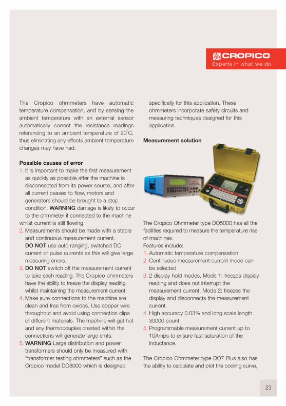
Measurement solution
The Cropico Ohmmeter type DO5000 has all thefacilities required to measure the temperature riseof machines. Features include:1. Automatic temperature compensation2. Continuous measurement current mode can
be selected3. 2 display hold modes, Mode 1: freezes display
reading and does not interrupt the measurement current, Mode 2: freezes the display and disconnects the measurement current.
4. High accuracy 0.03% and long scale length 30000 count
5. Programmable measurement current up to 10Amps to ensure fast saturation of the inductance.
The Cropico Ohmmeter type DO7 Plus also hasthe ability to calculate and plot the cooling curve,
Experts in what we do

24
displaying the temperature rise results innumerical and graphical format, also on screenand via data downloads.
Dry circuit testing - Switch and connectorcontact resistanceThe measurement of switch and connectorcontact resistance in accordance with DIN IEC512 and ASTM B539 requires that the opencircuit voltage of the measuring device shouldnot exceed 20mV DC. This low voltage avoidsthe breakdown of any oxides that may bepresent on the contacts. Ohmmeters in theCropico range have the facility for limiting thisopen circuit voltage.
Bonding and earthing resistance(metallisation resistance)Bonding should not be confused with earthingand is the electrical connection for componentsto ensure that they have an equal potential.Earthing is the connection of a circuit to theground earth. Both bonding and earthingconnections need to be measured to ensure thata suitably good low resistance joint is achievedand maintained. Typical applications for earthingcan be found in electricity distributionsubstations which have earthing systems for allthe equipment, usually in copper. Being made ofcopper the earthing is often stolen, makingregular checks essential. The Cropico range ofportable ohmmeters is ideal for thesemeasurements, being rugged in design andunaffected by the high magnetic fields found inthese substations.
Aircraft bonding All metal parts installed in an aircraft must beelectrically connected together (Bonded). Thisincludes all parts of the airframe. This electricalbonding of the airframe ensures that the Faradaycage protection is complete. In the case oflightning strikes on the aircraft, it will ensure thatall the current from the lightning strike will flowthrough the aircraft outer skin only. Thissafeguards the aircraft from the lightning currentflowing haphazardly though the aircraft anddamaging avionic systems essential to theaircraft safety. Aircraft manufacturers have strictprocedures for measuring the bondingresistance, both in production and maintenance.Ohmmeters used to measure this bondingresistance must be accurate, reliable, and able tomeasure with long leads. Ohmmeters in theCropico range fulfill these criteria and are usedby major aircraft manufacturers and operators.
25
Factor Name Symbol Factor Name Symbol
1015
1012
109
106
103
102
101
petateraGigaMegaKilo
Hectordeka
PTGMkhda
10-1
10-2
10-3
10-6
10-9
10-12
10-15
decicentimillomicronanopico
femto
dcmµnpf
Known Temperature Required Temperature Formulae
CelsiusCelsius
FahrenheitFahrenheit
KelvinKelvin
totototototo
FahrenheitKelvinCelsiusKelvinCelsius
Fahrenheit
oF=(1.8 X oC)+32K=oC+273.15oC=(oF-32)/1.8
K=(oF+459.67)/1.8oC=K-273.15
oF=(1.8xK)-459.67
oCoCoFoFKK
oFK
oCK
oCoF
Boiling point of water
Room temperature
Freezing point of water
Absolute zero
Celsius C Fahrenheit F Kelvin K
100 C
20 C
0 C
-273.15 C
212 F
68 F
32 F
-459.67 F
373.15 K
293.15 K
273.15 K
0 K
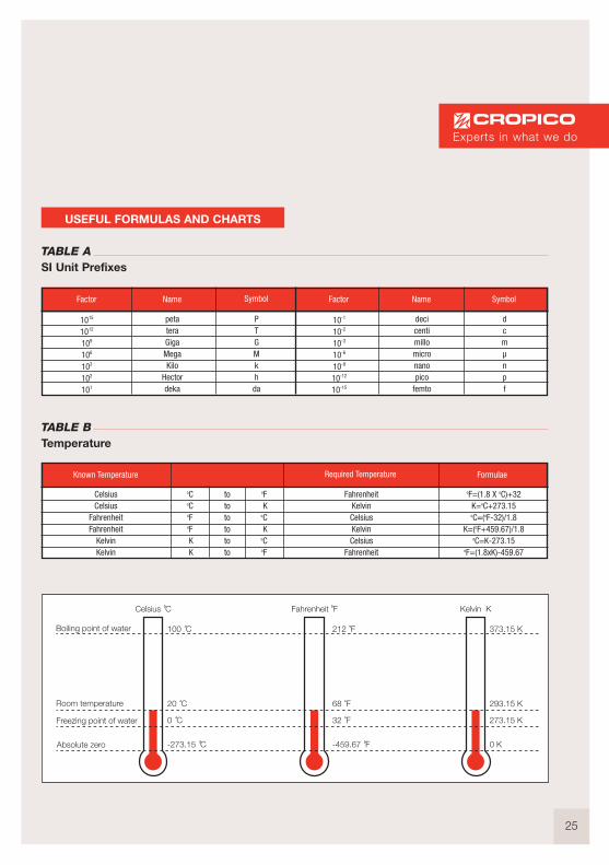
USEFUL FORMULAS AND CHARTS
TABLE A SI Unit Prefixes
TABLE B Temperature
Experts in what we do

26
Material Symbol Temperature coefficientper oC Conductivity per Ω-m Resistivity µΩ-cm
NickelIron
TungstenAluminium
CopperSilver
PlatinumGoldZincSteel
ManganinConstantan
NiFeWAlCuAgPtAuZnFeC
CuMnNiCuNi
ElementElementElementElementElementElementElementElementElement
AlloyAlloyAlloy
0.0058660.0056710.0044030.0041000.0039300.0038190.0037290.0037150.003847
0.003+/- 0.000015
-0.000074
1.43 x 10⁷
1.03 x 10⁷
1.89 x 10⁷
3.77 x 10⁷
5.95 x 10⁷
6.29 x 10⁷
0.96 x 10⁷
4.55 x 10⁷
1.69 x 10⁷
0.502 x 10⁷
0.207 x 10⁷
0.20 x 10⁷
6.939.665.282.651.671.5910.52.215.92
16.6248.2148.20
TABLE C Temperature coefficients conductivity and resistivity of resistance, at 20 oC
NOTE: Chart information is taken from multiple sources.
http://hyperphysics.phy-astr.gsu.edu/hbase/hframe.htm
lhttp://en.wikipedia.org/wiki/Electrical_resistivity
http://www.ndt-ed.org/EducationResources/CommunityCollege/Materials/Physical_Chemical/Electrical.htm

27
AWG Diameter AreaCopper
ResistanceApproximate
stranded metricequivalents
0000(4/0
000(3/0)
00(2/0)
0(1/0)
1
2
3
4
5
6
7
8
9
10
11
12
13
14
15
16
17
18
(inch)
0.46
0.4096
0.3648
0.3249
0.2893
0.2576
0.2294
0.2043
0.1819
0.162
0.1443
0.1285
0.1144
0.1019
0.0907
0.0808
0.072
0.0641
0.0571
0.0508
0.0453
0.0403
(mm)
11.68
10.4
9.266
8.251
7.348
6.544
5.827
5.189
4.621
4.115
3.665
3.264
2.906
2.588
2.305
2.053
1.828
1.628
1.45
1.291
1.15
1.02362
(kcmil)
211.6
167.8
133.1
105.5
83.69
66.37
52.63
41.74
33.1
26.25
20.72
16.52
13.08
10.38
8.23
6.53
5.17
4.10
3.26
2.59
2.05
1.62
(mm2)
107
85
67.4
53.5
42.4
33.6
26.7
21.2
16.8
13.3
10.5
8.37
6.63
5.26
4.17
3.31
2.62
2.08
1.65
1.31
1.04
0.823
(Ω/1 km)
0.16*
0.2*
0.25*
~0.3281
0.4*
0.5*
0.8*
1.5*
2.2*
3.2772
4.1339
5.21
6.572
8.284
10.45
13.18
16.614
20.948
(Ω/1000 ft)
0.049*
0.062*
0.077*
~0.1
0.12*
0.15*
0.24*
0.47*
0.67*
0.9989
1.26
1.588
2.003
2.525
3.184
4.016
5.064
6.385
196/0.4
126/0.4
80/0.4
>84/0.3
<84/0.3
56/0.3
50/0.25
>30/0.25
<30/0.25
32/0.2
>24/0.2
AWG Diameter AreaCopper
ResistanceApproximate
stranded metricequivalents
19
20
21
22
23
24
25
26
27
28
29
30
31
32
33
34
35
36
37
38
39
40
(inch)
0.0359
0.032
0.0285
0.0253
0.0226
0.0201
0.0179
0.0159
0.0142
0.0126
0.0113
0.01
0.0089
0.008
0.0071
0.0063
0.0056
0.005
0.0045
0.004
0.0035
0.0031
(mm)
0.9116
0.8128
0.7229
0.6438
0.5733
0.5106
0.4547
0.4049
0.3606
0.3211
0.2859
0.2546
0.2268
0.2019
0.1798
0.1601
0.1426
0.127
0.1131
0.1007
0.08969
0.07987
(kcmil)
1.29
1.02
0.81
0.64
0.51
0.40
0.32
0.255
0.201
0.160
0.127
0.100
0.080
0.063
0.050
0.040
0.032
0.025
0.020
0.016
0.012
0.010
(mm2)
0.653
0.518
0.41
0.326
0.258
0.205
0.162
0.129
0.102
0.081
0.0642
0.0509
0.0404
0.032
0.0254
0.0201
0.016
0.0127
0.01
0.00797
0.00632
0.00501
(Ω/1 km)
26.414
33.301
41.995
52.953
66.798
84.219
106.201
133.891
168.865
212.927
268.471
338.583
426.837
538.386
678.806
833
1085.958
1360.892
1680.118
2127.953
2781.496
3543.307
(Ω/1000 ft)
8.051
10.15
12.8
16.14
20.36
25.67
32.37
40.81
51.47
64.9
81.83
103.2
130.1
164.1
206.9
260.9
331
414.8
512.1
648.6
847.8
1080
<24/0.2
16/0.2
7/0.25
1/0.5, 7/0.2,30/0.1
30/0.1
7/0.15
1/0.25, 7/0.1
1/0.2, 7/0.08
TABLE D Wire gauges and resistivity
The North American wire gauges (AWG gauges) refer to sizes of copper wire. This table correspondsto a resistivity of Ú = 1.724 x 10⁻⁸ ohm m for copper at 20oC *the AWG system states areas of round copper wires in “circular mils”, which is the square of thediameter in mils. 1 mil = 0.001. Conductors larger than 4/0 AWG are generally identified by the area inthousands of circular mils (kcmil), where 1 kcmil = 0.5067 mm2
NOTE: Chart information is taken from http://hyperphysics.phy-astr.gsu.edu/hbase/Tables/wirega.html
Resistivity equationP = RA
LWhere P = electical resistivity ohm – metre
R = resistance of conductor ohmA = cross sectional area of conductor metre2
L = length of conductor metre
Experts in what we do

28
TABLE E Wire gauge equivalent SWG/AWG
NOTE: Chart information is taken from http://www.simetric.co.uk/siwire.htm
Number Imperial Standard Wire Gauge SWG Number Imperial Standard
Wire Gauge SWGAmerican
Wire Gauge AWG
gauge0000000 (7/0)000000 (6/0)00000 (5/0)0000 (4/0)000 (3/0)00 (2/0)0 (1/0)
123456789
10111213141516171819202122232425
inch. dia.-
0.5800000.5165000.4600000.4096420.3647960.3248610.2892970.2576270.229423
0.20430.18190.16200.14430.12850.11440.10190.09070.08080.07200.06410.05710.05080.04530.04030.03590.03200.02850.02530.02260.02010.0179
gauge2526272829303132333435363738394041424344454647484950515253545556
inch. dia.0.02000.01800.01640.01480.01360.01240.01160.01080.01000.00920.00840.00760.00680.00600.00520.00480.00440.00400.00360.00320.00280.00240.00200.00160.00120.0010
------
inch. dia.0.01790.01590.01420.01260.01130.01000.00890.00800.00710.00630.00560.00500.00450.00400.00350.00310.00280.00250.00220.00200.00180.00160.00140.00120.00110.0010
0.000880.000780.000700.000620.000550.00049
American Wire Gauge AWG
inch. dia.0.50000.46400.43200.40000.37200.34800.32400.30000.27600.25200.23200.21200.19200.17600.16000.14400.12800.11600.10400.09200.08000.07200.06400.05600.04800.04000.03600.03200.02800.02400.02200.0200
29
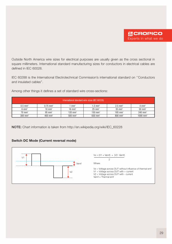
Outside North America wire sizes for electrical purposes are usually given as the cross sectional insquare millimeters. International standard manufacturing sizes for conductors in electrical cables aredefined in IEC 60028.
IEC 60288 is the International Electrotechnical Commission’s international standard on ‘’Conductorsand insulated cables’’.
Among other things it defines a set of standard wire cross-sections:
NOTE: Chart information is taken from http://en.wikipedia.org/wiki/IEC_60228
Switch DC Mode (Current reversal mode)
International standard wire sizes (IEC 60228)
0.5 mm2
6 mm2
70 mm2
300 mm2
0.75 mm2
10 mm2
95 mm2
400 mm2
1 mm2
16 mm2
120 mm2
500 mm2
1.5 mm2
25 mm2
150 mm2
630 mm2
2.5 mm2
35 mm2
185 mm2
800 mm2
4 mm2
50 mm2
240 mm2
1000 mm2
V1
V2
Vemf
Vx = (V1 + Vemf) + (V2- Vemf)
Where
Vx = Voltage across DUT without influence of thermal emfV1 = Voltage across DUT with + currentV2 = Voltage across DUT with - currentVemf = Thermal emf
2
Experts in what we do
30
Auto Zero Mode
OFF DU
T
No Current flow
V
P
C
P1
C1
ON DU
T
Current flow
V
P
C
P1
C1
Measurement cycle
Thermal emf emf across DUT+ thermal emf
Measurement 1: V1 = Vemf
Measurement 2: V2 = VDUT + Vemf
V auto Zero = V2 - V1
RDUT + V auto zero
31
GLOSSARY OF TERMS
Accuracy The uncertainty of a measurement which is the closeness of the agreement with the actual value.
Ambient temperature The nominal temperature that surrounds a device or system.
ATC Automatic temperature compensation.
AWG American wire gauge, also known as the "Brown and Sharpe" wire gauge,is used in the United States and other countries as a standard method ofdenoting wire diameter, especially for nonferrous, electrically conducting wire.
Bonding resistance
Cable A general term usually used to describe conductors of large diameter.
Cable Clamp A device for holding 1 metre lengths of cable and providing connections to the cable for current and potential connections.
Conductivity The reciprocal of electrical resistance.
Cooling Curve A graph plotting resistance values against time. Usually used when testingmotor or transformer to determine the maximum temperature achieved under full load conditions.
DMM Digital Multimeter.
Duplex Handspikes Consists of two sprung spikes mounted in a handle. One spike is the current connection and the other spike is the potential.
DUT Device under test.
Earth resistance
Emf Electromotive force is the rate at which energy is drawn from a source thatproduces a flow of electricity in a circuit; expressed in volts.
Electric current The rate of charge flow past a given point in an electric circuit, measuredin coulombs/second. The unit is the ampere.
Experts in what we do

32
Faraday cage A conducting cage used to shield electronic equipment.
IEC The International Electrotechnical Commission is the international standards and conformity assessment body for all fields of electrotechnology.
IEEE488 Is a short range digital communications bus. Originally created for use withautomated test equipment . Also known as GPIB (general purpose interface bus.)
Inductance Unit of measure is the Henry (H) and is best described as the behaviour of a coil of wire in resisting any change of electric current through it.
Kelvin The base unit of temperature in the International System of Units.
Kelvin connection A 4 wire method of connection which avoids errors due to wire resistance.
Kelvin clips Similar to crocodile clips but with each jaw electrically isolated. Permits both current and potential leads to be connected with a single clip.
Microhmmeter A resistance measuring instrument capable of measuring resistance with 1 microhm resolution.
Milliohmmeter A resistance measuring instrument capable of measuring resistance with 1 milliohm resolution.
Ohm Defined as the electrical resistance between two points on a conductor when a constant potential difference of 1 volt applied to these points produces in the conductor a current of 1 ampere.
Ohmmeter A generic name for all 4 terminal resistance measuring instruments.
Potential Leads The potential leads of a 4 terminal measuring instrument which measurethe voltage across the RX. Designated P and P1 or +U and –U dependingupon manufacturer.
PLC Programmable Logic Controller.
ppm Parts per million.
Precision The reproducibility and reliability of a measurement.
Range The maximum reading possible at the selected setting.
33
Resistance The degree to which a conductor opposes an electrical current.
Resistivity The electrical resistance of a uniform rod of unit length and unit cross- sectional area : the reciprocal of conductivity.
Resolution The smallest increment that a meter will display.
RS232 The RS232 interface is a serial port for transmission of data in serial bit format.
Rx Resistance of unknown value.
Scale length The largest value a measuring instrument can display for the range selected.
SI units The International System of units is a scientific method of expressing magnitude and quantity.
Source Leads The current leads of a 4 terminal measuring instrument. Designated C andC1 or +I and - I depending on manufacturer.
Stacking lead A measuring lead with 4mm banana plugs and 4 mm socket allowing onelead to plug into the other.
SWG Standard Wire gauge.
Thermal emf The open circuit voltage caused by the difference in temperature betweenthe hot and cold junctions of a circuit made from two dissimilar metals.
Thermocouple The junction of two dissimilar metals which has a voltage output proportional to the difference in temperature between the hot and cold junctions.
Temperature coefficient The change increase in conductor resistance per OC rise in temperature.
Wire A general term used to describe single drawn cylindrical metal and interchangeable with conductor or cable.
Experts in what we do

Want to know more?
Then contact us.
34
CropicoBracken Hill, South West Industrial Estate,Peterlee, Co. Durham. SR8 2SW, EnglandTel: +44 (0) 191 587 8748Fax: +44 (0) 191 586 0227Email: [email protected]: www.cropico.com
Resistance standards Temperature measurement Resistance decade boxes
Other products available from Cropico:

Experts in what we do

NOTES

This material is for information purposes only and is subject to change without notice. Cropico and its associatedcompanies accept no responsibility for any errors or consequential loss or damage which may
arise from misinterpretation of the information or procedures.
© Seaward Electronic Ltd. 2013
Experts in what we do

Your local Cropico distributor is:
Cropico, Bracken Hill, South West Industrial Estate,Peterlee, County Durham, SR8 2SW United Kingdom
Tel: +44 (0) 191 586 3511 Fax: +44 (0) 191 586 0227Email: [email protected] Web: www.cropico.com
Part No: 998A822Rev 3
Part of