Embed Size (px)
Citation preview

33
32015
41
128
30
343 100198 120
7051
789079
53349
322 325
50
366
49
4 1
466
4847
367
130
21
36
LSA 50.2
Low Voltage Alternator - 4 poleInstallation and maintenance

2
2021.09 / nElectric Power Generation Installation and maintenance
LSA 50.2Low Voltage Alternator - 4 pole
4099 en -
SAFETY MEASURESBefore using your machine for the first time, it is important to read the whole of this installation and maintenance manual.All necessary operations and interventions on this machine must be performed by a qualified technician.Our technical support service will be pleased to provide any additional information you may require.The various operations described in this manual are accompanied by recommenda-tions or symbols to alert the user to potential risks of accidents. It is vital that you unders-tand and take notice of the following warning symbols.
Warning symbol for an operation capable of damaging or destroying the machine or surrounding equipment.
Warning symbol for general danger to personnel.
Warning symbol for electrical danger to personnel.
SAFETY INSTRUCTIONSWe wish to draw your attention to the following 2 safety measures which must be complied with:
a) During operation, do not allow anyone to stand in front of the air outlet guards, in case anything is ejected from them.b) Do not allow children younger than 14 to go near the air outlet guards.A set of self-adhesive stickers depicting the various warning symbols is included with this maintenance manual. They should be positioned as shown in the drawing below once the machine has been fully installed.
WARNINGThe alternators must not be put into service until the machines in which they are to be incorporated have been declared compliant with EC Directives plus any other directives that may be applicable.This manual is to be given to the end user.The range of electric alternators and their derivatives, manufactured by us or on our behalf, comply with the technical requirements of the customs Union directives (EAC).
© - We reserve the right to modify the characteristics of this product at any time in order to incorporate the latest technological developments. The information contained in this document may therefore be changed without notice.
This document may not be reproduced in any form without prior authorisation.All brands and models have been registered and patents applied for.
WARNING
This manual concerns the alternator which you have just purchased.We wish to draw your attention to the contents of this maintenance manual.
3
2021.09 / nElectric Power Generation Installation and maintenance
LSA 50.2Low Voltage Alternator - 4 pole
4099 en -
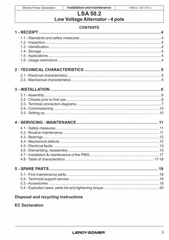
CONTENTS1 - RECEIPT .............................................................................................................4
1.1 - Standards and safety measures .................................................................................41.2 - Inspection ...................................................................................................................41.3 - Identification ...............................................................................................................41.4 - Storage ......................................................................................................................41.5 - Applications ................................................................................................................41.6 - Usage restrictions ......................................................................................................4
2 - TECHNICAL CHARACTERISTICS ....................................................................52.1 - Electrical characteristics .............................................................................................52.2 - Mechanical characteristics .........................................................................................5
3 - INSTALLATION ..................................................................................................63.1 - Assembly ....................................................................................................................63.2 - Checks prior to first use ..............................................................................................63.3 - Terminal connection diagrams ....................................................................................73.4 - Commissioning ........................................................................................................103.5 - Setting up .................................................................................................................10
4 - SERVICING - MAINTENANCE ......................................................................... 114.1 - Safety measures ...................................................................................................... 114.2 - Routine maintenance ............................................................................................... 114.3 - Bearings ...................................................................................................................124.4 - Mechanical defects ..................................................................................................124.5 - Electrical faults .........................................................................................................134.6 - Dismantling, reassembly ..........................................................................................154.7 - Installation & maintenance of the PMG .....................................................................174.8 - Table of characteristics ........................................................................................17-18
5 - SPARE PARTS .................................................................................................195.1 - First maintenance parts ............................................................................................195.2 - Technical support service .........................................................................................195.3 - Accessories .............................................................................................................195.4 - Exploded views, parts list and tightening torque .......................................................20
Disposal and recycling instructions
EC Declaration

4
2021.09 / nElectric Power Generation
Model
S/N
Enclosure
Th. Class
Weight
AVR
Date
Protection
Altitude
PF
Excitation
Freq.SpeedVoltage
PhaseV
min-1
Hz
kVAkW
AkVAkW
A
Connection
Cont.BR
40°C
Std by.PR
27°C
Made in Europe by Leroy-Somer
IEC 60034 - 1& 5ISO 8528 - 3NEMA MG1 - 32 & 33
MOTEURS LEROY-SOMER2 BD MARCELLIN LEROY - 16000 ANGOULÊME - FRANCE
Excitation415 v / 40°C
DE bearing
NDE bearing
No Load Full Load
www.leroy-somer.com
LSA
000-
1-14
8 a
Scan the code or go toGEN.LS1.DO
to check product data
12345678910
LSA
Installation and maintenance
LSA 50.2Low Voltage Alternator - 4 pole
4099 en -
1 - RECEIPT1.1 - Standards and safety measures Our alternators comply with most international standards.See the EC Declaration of Incorporation on the last page.
1.2 - Inspection On receipt of your alternator, check that it has not suffered any damage in transit. If there are obvious signs of knocks, contact the transporter (you may be able to claim on their insurance) and after a visual check, turn the machine by hand to detect any malfunction.
1.3 - Identification The alternator is identified by means of a nameplate fixed on the machine (see drawing).Make sure that the nameplate on the machine conforms to your order.So that you can identify your alternator quickly and accurately, we suggest you fill in its specifications on the nameplate below.
1.4 - Storage Prior to commissioning, machines should be stored:- away from humidity (< 90%); after a long period of storage, check the machine insulation. To prevent the bearings from becoming marked, do not store in an environment with significant vibration.
1.5 - Application This alternator is mainly designed to produce electricity in the context of applications involving the use of generators.
1.6 - Usage restrictions Use of the machine is restricted to operating conditions (environment, speed, voltage, power, etc) compatible with the characteri-stics indicated on the nameplate.

5
2021.09 / nElectric Power Generation Installation and maintenance
LSA 50.2Low Voltage Alternator - 4 pole
4099 en -
2 - TECHNICAL CHARACTERISTICS2.1 - Electrical characteristics This alternator is a machine without sliprings or revolving armature brushes, wound as “2/3 pitch”, 6-wire, with class H insulation and a field excitation system available in either AREP or PMG version (see diagrams and AVR manuals).• Electrical options - Stator temperature detection sensors- Bearing sensors (PTC, PT100, ...)- Space heaters- Terminal box with connector links for mounting protection or measurement C.T.- R791 interference suppression
2.2 - Mechanical characteristics - Steel frame- Cast iron end shields- Protected ball bearings, greased for life- Mounting arrangement: single bearing with standard feet and SAE flanges/coupling discs, two-bearing with SAE flange and standard cylindrical shaft extension- Drip-proof machine, self-cooled- Degree of protection: IP 23• Mechanical options - Protection against harsh environments- Regreasable ball bearings- Air inlet filter, air outlet labyrinth seals: IP 44To prevent excessive temperature rise caused by clogged filters, it is advisable to monitor the stator winding with thermal sensors (PTC or PT100).- Bearing temperature detection sensors
• AREP three-phase 6-wire
• PMG three-phase 6-wire
Varis
tor
Varis
tor
T1 T2 T3
T4 T5 T65+ 6-
T1 T2 T3
T4 T5 T65+ 6-
PMG
D350
D350
STATOR: 6-wire (marking T1 to T6)
STATOR: 6-wire (marking T1 to T6)
Auxiliary windingsMAIN FIELD
Voltage reference
MAIN FIELD
Voltage reference
EXCITER
Field
Armature
EXCITER
Field
Armature

6
2021.09 / nElectric Power Generation Installation and maintenance
LSA 50.2Low Voltage Alternator - 4 pole
4099 en -
3 - INSTALLATIONPersonnel undertaking the various operations indicated in this section must wear personal protective equipment appropriate for mechanical and electrical hazards.
3.1 - Assembly
All mechanical handling operations must be undertaken using suitable equipment and the machine must be horizontal. Check how much the machine weighs before choosing the lifting tool.During this operation, do not allow anyone to stand under the load.
• HandlingThe generously-sized lifting eyes are for handling the alternator only. They must not be used to lift the genset. The choice of lifting hooks or handles should be determined by the shape of the lifting eyes. Choose a lifting system which respects the integrity and the environment of the machine.
During this operation, do not allow anyone to stand under the load.
• Single-bearing couplingBefore coupling, check the compatibility between the alternator and the engine by performing:- undertaking a torsional analysis of the transmission (alternators data are available on request),- checking the dimensions of the flywheel and its housing, the flange, coupling discs and offset.
WARNING
When coupling the alternator to the prime mover, do not use the fan to turn the alternator or rotor.The holes of the coupling discs should be aligned with the flywheel holes by cranking the engine.Make sure the machine is securely bedded in position during coupling.Check that there is lateral play on the crankshaft.• Double-bearing coupling- Semi-flexible couplingCareful alignment of the machines is recommended, checking that the lack of concentricity and parallelism of both parts of the coupling do not exceed 0.1 mm.This alternator has been balanced with a 1/2 key.
• LocationThe location where the alternator is placed must be ventilated to ensure that the ambient temperature cannot exceed the data on the nameplate.
3.2 - Checks prior to first use
• Electrical checks
Under no circumstances should an alternator, new or otherwise, be operated if the insulation is less than 1 megohm for the stator and 100,000 ohms for the other windings.

7
2021.09 / nElectric Power Generation Installation and maintenance
LSA 50.2Low Voltage Alternator - 4 pole
4099 en -
There are 2 possible methods for restoring the above minimum values.a) Dry out the machine for 24 hours in a drying oven at a temperature of 110 °C (without the regulator).b) Blow hot air into the air intake, having made sure that the machine is rotating with the exciter field disconnected.Note : Prolonged standstillIn order to avoid these problems, we recommend the use of space heaters, as well as turning over the machine from time to time. Space heaters are only really effective if they are working continuously while the machine is stopped.
Ensure that the alternator has the degree of protection matching the defined environmental conditions.
• Mechanical checksBefore starting the machine for the first time, check that:- all fixing bolts are tight,- the length of bolt and the tightening torque are correct,- the cooling air is drawn in freely,- the protective grille and housing are cor-rectly in place,- the standard direction of rotation is clock-wise as seen from the drive end (phase rotation in order 1 - 2 - 3).For anti-clockwise rotation, swap 2 and 3.- the winding connection corresponds to the site operating voltage (see section 3.3).
WARNING
3.3 - Terminal connection diagramsTo modify the connection, change the position of the stator cables on the terminals. The winding code is specified on the nameplate.
Any intervention on the alternator terminals during reconnection or checks should be performed with the machine stopped. In no case should the internal connections in the terminal box be subjected to stresses due to cables connected by the user.

8
2021.09 / nElectric Power Generation Installation and maintenance
LSA 50.2Low Voltage Alternator - 4 pole
4099 en -
• AREP or PMG three-phase 6-wire
N
T1
T4
T3T6
T5
T2
L1(U)
L3(W) L2(V)
L1(U)
L3(W)
T1
T4T3
T6
T5 T2L2(V)
(*)
60 Hz50 Hz
380 - 415 380 - 480
440
380 - 416
-
-
-
6S
7S
8S
60 Hz50 Hz
D350 : U => T1, V => T2, W => T3
9S 600
220 - 240
220 - 240
220 - 277
240 - 254 -
-
6S
7S
8S
L1(U)
L2(V)
L3(W)
T4
T6
T5
T1
T2
T3
N
D350 : U => T1, V => T2, W => T3
L1(U)
L2(V)
L3(W)
T4
T6
T5
T1
T2
T3
3PHD
3PHF
NDE
NDE
In case of reconnection, ensure that AVR voltage sensing is correct!The factory can supply a set of flexible shunts and special connection links as an option for making these connections (*).
Connection codes Factory connectionVoltage / Detection
With winding 9: D350 voltage sensing + transfo (diagram on request)
Winding
Winding

9
2021.09 / nElectric Power Generation Installation and maintenance
LSA 50.2Low Voltage Alternator - 4 pole
4099 en -
• Option connection diagram
ST1000 ohms
Remote voltage potentiometer
Voltage adjustmentvia remote potentiometer
P1P2
T4
T4
Ph1
Ph2
Ph3
101
102
103
104
500W - 220 V
121
122122
123
124124
122122
124124123
121 103104104
105106106
107108108
103
104104
PH 1
105
106106
PH 2
107
108108
PH 3
DE
NDE
WhiteRedRed
WhiteRedRed
White
Red Red Red
Red RedRedWhite White
Current transformer connection Anti condensation heater Thermistor temperature (PTC)
Shield (PT 100) Stator (PT 100)
Neutral link
130 °CBlue wire
150 °CBlack wire
180 °CRed/white wire
In/4 - Secondary 1 ACoupling D
6-wire
- PH 1

10
2021.09 / nElectric Power Generation Installation and maintenance
LSA 50.2Low Voltage Alternator - 4 pole
4099 en -
• Connection checks
Electrical installations must comply with the current legislation in force in the country of use.Check that:- The residual circuit-breaker conforms to legislation on protection of personnel, in force in the country of use, and has been correctly installed on the alternator power output as close as possible to the alternator. (In this case, disconnect the wire of the interference suppression module linking theneutral).- Any protection devices in place have not been tripped.- If there is an external AVR, the connections between the alternator and the cabinet are made in accordance with the connection diagram.- There is no short-circuit phase-phase or phase-neutral between the alternator output terminals and the generator set control cabinet (part of the circuit not protected by circuitbreakers or relays in the cabinet).- The machine should be connected with the busbar separating the terminals as shown in the terminal connection diagram. - The alternator earth terminal inside the terminal box is connected to the electrical earth circuit- The earth terminal is connected to the frame.The connections inside the terminal box must never be subjected to stress due to cables connected by the user.
Diameter M6 M8 M10 M12Torque 4 Nm 10 Nm 20 Nm 35 NmTolerance ± 15%
3.4 - Commissioning
The machine can only be started up and used if the installation is in accordance with the regulations and instructions defined in this manual.The machine is tested and set up at the factory. When first used with no load, make sure that the drive speed is correct and stable (see the nameplate). With the regreasable bearing option, we recommend greasing the bearings at the time of commissioning (see section 4.3).On application of the load, the machine should achieve its rated speed and voltage; however, in the event of abnormal operation, the machine setting can be altered (follow the adjustment procedure in section 3.5). If the machine still operates incorrectly, the cause of the malfunction must be located (see section 4.5).
3.5 - Setting up
The various adjustments during tests must be made by a qualified engineer.Ensure that the drive speed specified on the nameplate is reached before commencing adjustment.After operational testing, replace all access panels or covers.The AVR is used to make any adjustments to the machine.

11
2021.09 / nElectric Power Generation Installation and maintenance
LSA 50.2Low Voltage Alternator - 4 pole
4099 en -
4 - SERVICING - MAINTENANCE4.1 - Safety measuresServicing or troubleshooting must be carried out strictly in accordance with instructions so as to avoid the risk of accidents and to maintain the machine in its original state.
All such operations performed on the alternator should be undertaken by personnel trained in the commissioning, servicing and maintenance of electrical and mechanical components, who mustwear personal protective equipment appropriate for mechanical and electrical hazards.Before any intervention on the machine, ensure that it cannot be started by a manual or automatic system and that you have understood the operating principles of the system.
Warning : During and after running, the alternator will reach temperatures hot enough to cause injury, such as burns.
4.2 - Routine maintenance
• Checks after start-upAfter approximately 20 hours of operation, check that all fixing bolts on the machine are still tight, plus the general state of the machine and the various electrical connections in the installation.
• Electrical servicingCommercially-available volatile degreasing agents can be used.
Do not use: trichlorethylene, perchlo-rethylene, trichloroethane or any alkaline products.
These operations must be performed at a cleaning station, equipped with a vacuum system that collects and flushes out the products used.The insulating components and the impregnation system are not at risk of damage from solvents. Avoid letting the cleaning product run into the slots.Apply the product with a brush, sponging frequently to avoid accumulation in the housing. Dry the winding with a dry cloth. Let any traces evaporate before reassembling the machine.
• Mechanical servicing
Cleaning the machine using water or a highpressure washer is strictly prohi-bited. Any problems arising from such treatment are not covered by our warranty.Degreasing: Use a brush and detergent (suitable for paintwork).Dusting: Use an air gun.If the machine is fitted with air inlet and outlet filters, the maintenance personnel should clean them routinely at regular intervals. In the case of dry dust, the filter can be cleaned using compressed air and/or replaced if it is clogged.After cleaning the alternator, it is essential to check the winding insulation (see sections 3.2 and 4.5).
WARNING
WARNING

12
2021.09 / nElectric Power Generation Installation and maintenance
LSA 50.2Low Voltage Alternator - 4 pole
4099 en -
4.4 - Mechanical defects
Fault Action
BearingExcessive overheating of one or both bearings(bearing temperature 80°C above the ambient temperature)
- If the bearing has turned blue or if the grease has turned black, change the bearing.
- Bearing not fully locked (abnormal play in the bearing cage) - End shields incorrectly aligned
Abnormal temperature
Excessive overheating of alternator frame (more than 40° C above the ambient temperature)
- Air flow (inlet-outlet) partially clogged or hot air is being recycled from the alternator or engine
- Alternator operating at too high a voltage (>105% of Un on load)
- Alternator overloaded
VibrationsToo much vibration
- Misalignment (coupling)- Defective mounting or play in coupling- Rotor balancing fault (Engine - Alternator)
Excessive vibration and humming noise coming from the machine
- Phase imbalance - Stator short-circuit
Abnormal noise
Alternator damaged by a significant impact, followed by humming and vibration
- System short-circuit- MisparallelingPossible consequences - Broken or damaged coupling- Broken or bent shaft end- Shifting and short-circuit of main field- Fan fractured or coming loose on shaft- Irreparable damage to rotating diodes/AVR, surge suppressor
4.3 - BearingsThe bearings are permanently greased Approximate life of the grease (depending on use) =
20,000 hours or 3 years.As an option, the bearings are regreasable Regreasing interval: 3600 hrs of operation
DE bearing: Amount of grease: 60 grNDE bearing: Amount of grease: 50 gr
Standard grease LITHIUM - standard - NLGI 3Grease used in the factory ESSO - Unirex N3
It is imperative to lubricate the alternator during operation and on first use. Before using another grease, check for compatibility with the original one.
13
2021.09 / nElectric Power Generation Installation and maintenance
LSA 50.2Low Voltage Alternator - 4 pole
4099 en -
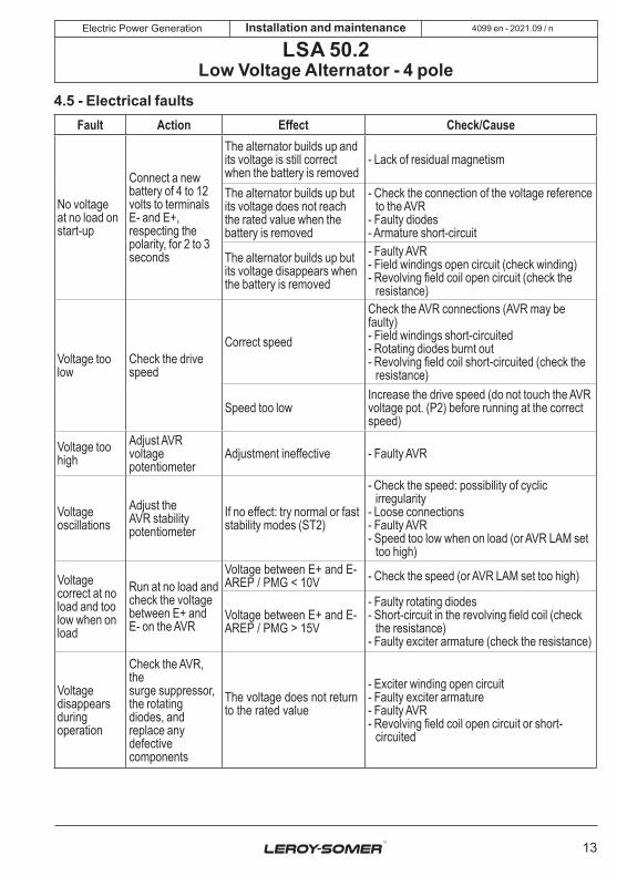
4.5 - Electrical faultsFault Action Effect Check/Cause
No voltageat no load on start-up
Connect a new battery of 4 to 12 volts to terminals E- and E+, respecting the polarity, for 2 to 3 seconds
The alternator builds up and its voltage is still correct when the battery is removed
- Lack of residual magnetism
The alternator builds up but its voltage does not reach the rated value when the battery is removed
- Check the connection of the voltage reference to the AVR
- Faulty diodes- Armature short-circuit
The alternator builds up but its voltage disappears when the battery is removed
- Faulty AVR- Field windings open circuit (check winding)- Revolving field coil open circuit (check the
resistance)
Voltage too low
Check the drive speed
Correct speed
Check the AVR connections (AVR may be faulty)- Field windings short-circuited- Rotating diodes burnt out- Revolving field coil short-circuited (check the
resistance)
Speed too lowIncrease the drive speed (do not touch the AVR voltage pot. (P2) before running at the correct speed)
Voltage too high
Adjust AVR voltagepotentiometer
Adjustment ineffective - Faulty AVR
Voltageoscillations
Adjust theAVR stabilitypotentiometer
If no effect: try normal or fast stability modes (ST2)
- Check the speed: possibility of cyclic irregularity
- Loose connections- Faulty AVR- Speed too low when on load (or AVR LAM set
too high)
Voltage correct at no load and too low when onload
Run at no load and check the voltage between E+ and E- on the AVR
Voltage between E+ and E- AREP / PMG < 10V - Check the speed (or AVR LAM set too high)
Voltage between E+ and E- AREP / PMG > 15V
- Faulty rotating diodes- Short-circuit in the revolving field coil (check
the resistance)- Faulty exciter armature (check the resistance)
Voltagedisappearsduring operation
Check the AVR, thesurge suppressor,the rotating diodes, and replace any defectivecomponents
The voltage does not return to the rated value
- Exciter winding open circuit- Faulty exciter armature- Faulty AVR- Revolving field coil open circuit or short-
circuited

14
2021.09 / nElectric Power Generation Installation and maintenance
LSA 50.2Low Voltage Alternator - 4 pole
4099 en -
• Checking the windingYou can check the winding insulation by performing a high voltage test. In this case, you must disconnect all AVR wires.
WARNING
Damage caused to the AVR in such conditions is not covered by our warranty.
• Checking the windings and rotating diodes using separate excitation
During this procedure, make sure that the alternator is disconnected from any external load and inspect the terminal box to check that the connections are fully tightened.1) Stop the unit, disconnect and isolate the AVR wires.2) There are two ways of creating an assembly with separate excitation.
Assembly A: Connect a 12 V battery in series with a rheostat of approximately 50 ohms - 300 W and a diode on both exciterfield wires (5+) and (6-).
6 - 5 +
1A diode
12V battery
Rh. 50 -300W
-+
ASSEMBLY AField
Assembly B: Connect a “Variac” variable power supply and a diode bridge on both exciter field wires (5+) and (6-).Both these systems should have characteristics which are compatible with the field excitation power of the machine (see the nameplate).3) Run the unit at its rated speed.4) Gradually increase the exciter field current by adjusting the rheostat or the variac and measure the output voltages on L1 - L2 - L3, checking the excitation voltage and current at no load (see the machine nameplate or ask for the factory test report).When the output voltage is at its rated value and balanced within 1% for the rated excitation level, the machine is in good working order. The fault therefore comes from the AVR or its associated wiring (ie. sensing, auxiliary windings).
1A diode
-
+
6 - 5 +
Variac AC220V
DC12V
50 60
7080
90
100
40
3020
10
0
ASSEMBLY B Field
• Checking the diode bridgeA diode in good working order should allow the current to flow only in the anode-to-cathode direction.
CA
- -
++ ~~~
C C C
A A A
C C C
A A A
~ ~ ~
-
CA
+
-
CA
+
A n o d e C a t h o d e

15
2021.09 / nElectric Power Generation Installation and maintenance
LSA 50.2Low Voltage Alternator - 4 pole
4099 en -
4.6 - Dismantling, reassembly
During the warranty period, this operation should only be carried out in an approved workshop or in our factory, otherwise the warranty may be invalidated.Whilst being handled, the machine should remain horizontal (rotor not locked in position). Check how much the machine weighs before choosing the lifting method.
• Tools requiredTo fully dismantle the machine, we recommend using the tools listed below:- 1 ratchet spanner + extension- 1 torque wrench- 1 set of flat spanners: 8 mm, 10 mm, 18 mm- 1 socket set: 8, 10, 13, 16, 18, 21, 24, 30 mm- 1 socket with male ferrule: 5 mm- 1 puller
• Screw tightening torqueSee section 5.4.
• Access to diodes- Open the air intake grille (51).- Disconnect the diodes.- Check the diodes using an ohmmeter or a battery lamp.If the diodes are faulty:- Remove the surge suppressor.
- Remove the «H» nuts for mounting the diode bridges on the support.- Change the crescents, respecting the polarity.
• Access to connections and the regulation systemAccess directly by removing the top of the terminal box lid (48) or the AVR access door (466).
• Replacing the NDE bearing on single bearing machines- Remove the air intake grille (51).- Remove the top of the terminal box lid (48) and the side panels (366) and (367).- Remove the hook (21) and the cover rear panel (47).- Replace the hook (21) in order to manipulate the flange.- Disconnect the exciter wires (5+,6-).- Remove the screws from the inner bearing cap (78). - Remove the screws and and take out the shield (36).- Take out the antifriction bearing (70) using a puller with a central screw (see drawing below).
- Fit the new antifriction bearing onto the shaft after heating it by induction to approximately 80 °C.- Mount the new preloading (wavy) washer (79) + the new “O” ring seal (349) in the shield (36).
WARNING

16
2021.09 / nElectric Power Generation Installation and maintenance
LSA 50.2Low Voltage Alternator - 4 pole
4099 en -
- Screw a threaded rod into the thrust bearing (78).- Refit the end shield on the machine using a dowel and nut in the shaft extension (see drawing).- Slide the threaded rod into the shield hole to make it easier to assemble (see basic diagram).
4 78 36
Rotor
NDE shield
DowelNut
Threaded rod
- Fit the thrust bearing screws (78), remove the threaded rod, fit the other screws and tighten up the assembly.- Tighten the shield (36) screws.- Reconnect exciter wires E+, E-.- Finish reassembling the cover.
WARNINGWhen dismantling the shields, you will need to change the antifriction bearings, the “O” ring seal, the preloading (wavy) washer and adhesive paste.
• Replacing the DE bearing- Remove the air outlet grille (33).- Remove the screws from the DE shield (30) and the screws from the inner bearing retainer (68).- Remove the shield (30).- Take out the ball bearing (60) using a puller with a central screw.
- Fit the new bearing, after heating it by induction to approximately 80 °C.- Screw two threaded rods into the thrust bearing.- Refit the shield (30) on the machine.- Slide the threaded rod into the shield hole to make it easier to assemble (see basic diagram).- Tighten the bottom thrust bearing screws, remove the threaded rod and fit the other screws.- Tighten the shield (30) screws.- Refit the air outlet grille (33).
• Dismantling the rotor assembly- Remove the NDE shield (36).- Remove the DE shield (30) if it is a double-bearing machine.- Support the DE rotor (4) with a strap or with a support constructed in accordance with the following drawing.- Move the strap as the rotor moves in order to distribute the weight over it.
WARNING
When dismantling the rotor involves changing parts or rewinding, the rotor must be rebalanced.

17
2021.09 / nElectric Power Generation Installation and maintenance
LSA 50.2Low Voltage Alternator - 4 pole
4099 en -
• Reassembling the machine- Mount the rotor (4) in the stator (1) (see drawing above) taking care not to knock the windings.- Slide the threaded rod into the shield hole to make it easier to assemble (see diagram).- Fit the thrust bearing screws (78), remove the threaded rod, fit the other screw and tighten up the assembly.- Tighten the shield (36) screws.- Reconnect exciter wires E+, E-.- Finish reassembling the cover.- Refit the flange (30) on the stator (1).- Tighten the screws (30).
If using a double-bearing machine:- Finish reassembling the cover.- Screw a threaded rod into the thrust bearing.- Refit the shield (30) on the machine.- Slide the threaded rod into the shield hole to make it easier to assemble (see basic diagram).- Fit the thrust bearing screws, remove the threaded rod, fit the other screw and tighten up the assembly.- Tighten the shield (30) screws.- Refit the air outlet grille (33).- Check that the machine assembly is correctly mounted and that all screws are tightened.
• Dismantling and reassembly of the filters- Remove the grille (51) then take out the filter (52). Change the filter if necessary; please refer to section 4.2 for cleaning the filter.To replace, follow the instructions in reverse order.- On certain versions, the filters are incorporated in the terminal box panels.
52
51
4.7 - Installation and maintenance of the PMGThe PMG reference is PMG 5.See the PMG manual ref : 4211.
4.8 - Table of characteristicsTable of average values:Alternator - 4 poles - 50 Hz - Standard winding No. 6S (6-wire) (400V for the excitation values).The voltage and current values are given for no-load operation and operation at rated load with separate field excitation.All values are given at ± 10% and may be changed without prior notification (for exact values, consult the test report).

18
2021.09 / nElectric Power Generation Installation and maintenance
LSA 50.2Low Voltage Alternator - 4 pole
4099 en -
• Three-phase: 4-pole AREP excitationResistances at 20 °C (Ω)
Type StatorL/N Rotor Exciter
fieldExciter
armatureS4 0.0021 0.385 12.728 0.096
M6 0.0016 0.429 12.728 0.096
L7 0.0014 0.456 12.728 0.096
L8 0.0012 0.500 12.728 0.096
VL10 0.0010 0.549 12.728 0.096
Resistances of auxiliary windingsAREP at 20 °C (Ω)
Type X1, X2 Z1, Z2
S4 0.1417 0.1742
M6 0.1232 0.1722
L7 0.1136 0.1509
L8 0.1137 0.1527
VL10 0.1051 0.1635
Field excitation current i exc (A)AREP - 400V - 50 Hz“i exc”: excitation current of the exciter field
Type No load At rated load
S4 0.78 3.53
M6 0.82 3.6
L7 0.85 3.48
L8 0.78 3.38
VL10 0.78 3.26
For 60 Hz machines, the “i exc” values are approximately 5 to 10 % lower.
• Table of weights(values given for information only)
Type Total weight (kg) Rotor (kg)
S4 2330 831
M6 2530 932
L7 2800 1003
L8 3010 1081
VL10 3300 1191
After operational testing, it is essential to replace all access panels or covers.

19
2021.09 / nElectric Power Generation Installation and maintenance
LSA 50.2Low Voltage Alternator - 4 pole
4099 en -
5 - SPARE PARTS5.1 - First maintenance partsEmergency repair kits are available as an option.They contain the following items :Emergency kit AREP/PMG 5163978AVR D350 -Diode bridge assembly -Surge suppressor -
Single-bearing kit 4521357Non drive end bearing -«O» ring -Preloading (wavy) washer -
Double-bearing kit 4582501Non drive end bearing -Drive end bearing -«O» ring -Preloading (wavy) washer -
5.3 - Accessories • Space heater for use when stoppedThe space heater must run as soon as the alternator stops. It is installed at the rear of the alternator. Its standard power is 500W with 220V or 250W with 110V on request.
Warning: the power supply is present when the machine has stopped.
• Temperature sensors with thermistors (PTC)These are thermistor triplets with a positive temperature coefficient installed in the stator winding (1 per phase). There can be a maximum of 2 triplets in the winding (at 2 levels: warning and trip) and 1 or 2 thermistors in the shields.These sensors must be linked to adapted sensing relays (supplied optionally).Cold resistance of cold thermistor sensors: 100 to 250 Ω per sensor.
• Connection accessories - 6-wire machinesRequirements for coupling (F):- 3 connection bars
5.2 - Technical support serviceOur technical support service will be pleased to provide any additional information you may require.
For all spare parts orders or technical support requests, send your request to [email protected] or your nearest contact, whom you will find at www.lrsm.co/support indicating the comp-lete type of machine, its number and the information indicated on the nameplate.
Part numbers should be identified from the exploded views and their description from the parts list.
To ensure that our products operate correctly and safely, we recommend the use of original manufacturer spare parts.In the event of failure to comply with this advice, the manufacturer cannot be held responsible for any damage.
After operational testing, it is essential to replace all access panels or covers.

20
2021.09 / nElectric Power Generation
33
320
15
41 128
30
343
100
198
120
7051
7890
7953
349
322
325
50 366
49
41
466
4847
367
466
130 2136
Installation and maintenance
LSA 50.2Low Voltage Alternator - 4 pole
4099 en -
5.4 - Exploded views, parts list and tightening torque• Single bearing

21
2021.09 / nElectric Power Generation
68
320
1541 128
60
343
100
198
120
7051
53
7890
7934
9
3033
50 366
49
41
466
4847
367
466
130 2136
Installation and maintenance
LSA 50.2Low Voltage Alternator - 4 pole
4099 en -
• Two-bearing

22
2021.09 / nElectric Power Generation Installation and maintenance
LSA 50.2Low Voltage Alternator - 4 pole
4099 en -
Ref. Qty Description ScrewØ
TorqueN.m Ref. Qty Description Screw
ØTorque
N.m
1 1 Stator assembly - - 78 1 Inner bearing retainer M8 20
4 1 Rotor assembly - - 79 1 Preloading (wavy) washer - -
15 1 Fan - - 90 1 Exciter field (stator) M8 20
21 1 Lifting eye - - 100 1 Exciter armature (rotor) - -
30 1 Drive end (DE) shield M12 69 120 1 Terminal support - -
33 1 Air outlet grille M6 3 128 3 Phase busbar M12 35
36 1 Non drive end (NDE) shield M12 69 130 1 Neutral busbar M12 35
41 1 Terminal box frontpanel M6 8.3 198 1 Voltage regulator
(AVR) - -
47 1 Terminal box rear panel M6 8.3 320 1 Coupling sleeve - -
48 1 Terminal box lid M6 8.3 322 3 Coupling disc M20 340
49-50 1 Inspection door M6 8.3 325 - Spacer shim - -
51 1 Air intake grille M6 8.3 343 1 Diode bridgeassembly M6 4
53 1 Sealing cap - - 349 1 O ring seal - -
60 1 Drive end (DE)bearing - - 366 1 Terminal box side
panel M6 8.3
68 1 Inner bearing retainer - - 367 1 Terminal box side panel with inspection door M6 8.3
70 1 Non drive end (NDE)bearing - - 466 1 AVR inspection door - -

23
2021.09 / nElectric Power Generation Installation and maintenance
LSA 50.2Low Voltage Alternator - 4 pole
4099 en -
Disposal and recycling instructionsWe are committed to limiting the environmental impact of our activity. We continuously monitor our production processes, material sourcing and product design to improve recyclability and minimise our environmental footprint.These instructions are for information purposes only. It is the user’s responsibility to comply with local legislation regarding product disposal and recycling.
Recyclable materials Our alternators are mainly constructed from iron, steel and copper materials, which can be reclaimed for recycling purposes.These materials can be reclaimed through a combination of manual dismantling, mechanical separation and melting processes. Our technical support depart-ment can provide detailed directions on how to dismantle products on request.
Waste & hazardous materials The following components and materials require special treatment and must be separated from the alternator before the recycling process:- electronic materials found in the terminal box, including the automatic voltage regulator (198), current transformers (176), interference suppression module and other semi-conductors.- diode bridge (343) and surge suppressor (347), found on the alternator rotor.- major plastic components, such as the terminal box structure on some products.
These components are usually marked with information concerning the type of plastic.All materials listed above need special treatment to separate waste from reclaimable materials and should be entrusted to specialist recycling companies.
The oil and grease from the lubrication system should be treated as hazardous waste and must be treated in accordance with local legislation.
Our alternators have a specified lifetime of 20 years. After this period, the operation of the product should be stopped, regardless of its condition. Any further operation after this period will be under the sole responsi-bility of the user.

24
2021.09 / nElectric Power Generation Installation and maintenance
LSA 50.2Low Voltage Alternator - 4 pole
4099 en -

25
2021.09 / nElectric Power Generation Installation and maintenance
LSA 50.2Low Voltage Alternator - 4 pole
4099 en -
Moteurs Leroy-Somer Siege social : Boulevard Marcellin Leroy CS 10015 - 16915 Angoulême cedex 9 - France SAS au capital de 38 679 664 € - RCS Angoulême 338 567 258
Moteurs Leroy-Somer Boulevard Marcellin Leroy - CS 10015 16915 Angoulême cedex 9 - France
4152 en - 2021.07 / u
Angoulême, 1st July 2021
EC Declaration Moteurs Leroy-Somer declares hereby that the electric generators of the types:
LSA 40 – LSA 42.3 – LSA 44.3 – LSA 46.3 – LSA 47.2 – LSA 47.3 – LSA 49.1 – LSA 49.3 – LSA 50.1 – LSA 50.2 – LSA 51.2 – LSA 52.2 – LSA 52.3 – LSA 53 – LSA 53.1 – LSA 53.2 – LSA 54 – LSA 54.2 – TAL 040 – TAL 042 – TAL 044 – TAL 046 – TAL 047 – TAL 0473 – TAL 049 – LSAH 42.3 – LSAH 44.3
as well as their derivatives, manufactured by Leroy-Somer or on Leroy-Somer's behalf:
MOTEURS LEROY-SOMER Boulevard Marcellin Leroy 16015 Angoulême France
MLS HOLICE STLO.SRO Sladkovskeho 43 772 04 Olomouc République Tchèque
MOTEURS LEROY-SOMER 1, rue de la Burelle Boite Postale 1517 45800 St Jean de Braye France
LEROY-SOMER ELECTRO- TECHNIQUE Co., Ltd No1 Aimosheng Road, Galshan Town, Cangshan District. Fuzhou, Fujian 350026 Chine
NIDEC INDUSTRIAL AUTOMATION INDIA PRIVATE Ltd - BANGALORE #45, Nagarur, Huskur Road Off Tumkur Road, Bengaluru-562 162 Inde
NIDEC INDUSTRIAL AUTOMATION INDIA PRIVATE Ltd - HUBLI #64/A, Main Road, Tarihal Industrial Area, Tarihal, Hubli-580 026 Inde
meet the requirements of the following standards and directives:
Declaration of compliance: - Low Voltage Directive Nr 2014/35/EU dated 26th February 2014.- EN and IEC 60034-1, 60034-5 and 60034-22.- ISO 8528-3 “Reciprocating internal combustion engine driven alternating current generating sets. Part
3. Alternating current generators for generating sets”.
These generators also comply with the ROHS Directive Nr 2011/65/EU dated 8th June 2011 and its Annex II Nr 2015/863 dated 31st March 2015, as well as the EMC Directive Nr 2014/30/EU dated 26th February 2014.
Declaration of incorporation: These generators are designed to meet the essential "Partly completed machinery" requirements of Machinery Directive Nr 2006/42/EC, as well as Annex VII, part B of this directive and the aforementioned standards.
As a result, these "Partly completed machinery" are designed to be incorporated into Electrical Gen-Sets complying with the Machinery Directive Nr 2006/42/EC dated 17th May 2006.
WARNING: The here mentioned generators should not be commissioned until the corresponding Gen-Sets have been declared in compliance with the Directives Nr 2006/42/EC, 2014/30/EU, 2011/65/EU and 2015/863, as well as with other relevant Directives.
Moteurs Leroy-Somer undertakes to transmit, in response to a reasoned request by the national authorities, relevant information on the generator.
Technical Managers J.P. CHARPENTIER – Y. MESSIN
The contractual EC Declaration of compliance and incorporation can be obtained from your contact on request.

26
2021.09 / nElectric Power Generation Installation and maintenance
LSA 50.2Low Voltage Alternator - 4 pole
4099 en -

[email protected] www.lrsm.co/support
Design
Life Extension
Optimisation
Start-up
Operation
•Consulting & specification•Maintenance
contracts
•Reconditioning•System upgrade
•Monitoring•System audit
•Commissioning•Training
•Genuine spare parts•Repair services
Our worldwide service network of over 80 facilities is at your service.This local presence is our guarantee for fast and efficient repair, support and maintenance services.Trust your alternator maintenance and support to electric power generation experts. Our field personnel are 100% qualified and fully trained to operate in all environments and on all machine types.We have a deep understanding of alternator operation, providing the best value service to optimise your cost of ownership.
Where we can help:
Contact us:Americas: +1 (507) 625 4011Europe & rest of the world: +33 238 609 908Asia Pacific: +65 6250 8488 China: +86 591 88373036India: +91 806 726 4867
Scan the code or go to:
Service & Support

www.emersonindustrial.com
- 2021.09 / n
www.leroy-somer.com/epg
4099 en
Linkedin.com/company/leroy-somerTwitter.com/Leroy_Somer_enFacebook.com/LeroySomer.Nidec.enYouTube.com/LeroySomerOfficiel