Embed Size (px)
Citation preview

User's Guidefor type ACS50
AC Drivesfrom 0.18 to 0.75 kW
DriveIT
Low VoltageDrives

3AFE 68247756 REV C ENEffective: 30.01.2004
© 2004 ABB Oy. All Rights reserved.
ABB OyAC DrivesP.O. Box 184FIN-00381 HELSINKIFINLANDTelephone 358 10 22 11Fax +358 10 22 22681Internet http://www.abb.com
ACS50 User�s Guides in other languages can be found from internet: http://www.abb.com.Enter ACS50 UG into the Search field.

3
ation necessary to install and start-up
ted on the rating plate. W = manufacturing week
ACS50-01_-____-_
rol cable (EMC units
ensure that the ds to the order.
= No current (I2): A, 04A3 = 4.3 A
-15%-15%
Safety instructionsRead the following instructions carefully before proceeding with the installation.Warning! Dangerous voltage!Only a competent electrician may install ACS50.Never work on the drive, the motor cable or the motor when main power is applied. After switching off the input power, always wait at least for 5 minutes to let the intermediate circuit capacitors discharge before you start working on the drive.Note: DIP switches are at a dangerous voltage.Note: Even when the motor is stopped, dangerous voltages are present at power circuit terminals L/R, N/S, T1/U, T2/V and T3/W. Note: Even when the unit is powered down, there may be dangerous external voltages connected from outside to the relay output terminals.Warning! Hot surfaces!During operation, the cooling element may reach high temperature (>80 °C). Make sure to follow the installation instructions.
General safety instructionsACS50 starts the motor automatically after a supply break if the external start signal is on.Never attempt to repair a broken unit. ACS50 is not a field repairable unit. Contact the supplier for replacement.Install ACS50 in a locked or tool-openable space. Do not connect input power to the unit more than once every three minutes.Altering the DIP switches will affect the function and performance of ACS50. Check that the changes will not cause any risk to persons or property.
About this manualThis guide provides informthe unit.
Delivery check
Serial number (S/N) is prin(Y = manufacturing year, W
The delivery includes:1. ACS50 2. User�s guide3. Two clamps for the contonly)Check the rating plate anddelivered device correspon
EMC filter: E = Built in, NMax. continuous output01A4 = 1.4 A, 02A2 = 2.2Supply voltage (U1):1 = 110�120 VAC +10%/2 = 200�240 VAC +10%/

4
rol potentiometers, page 12
y output terminals, page 14
r cable terminals, page 13. Sliding r provides additional insulation. Slide over left to close.
ctive earth (PE), page 13
switches, page 10
rol cable terminals, page 14
p plate, page 15 (EMC units only)
r cable shield, page 13
Overview of the unitACS50 drive controls the speed of a 3-phase AC induction motor.
Input terminals, page 13
Power on LED, page 17
Fault LED, page 17
Cont
Analogue input signal selector (voltage/current), page 14
Mounting clip, pages 8 - 9
Rela
Motocovethe c
Prote
DIP
Cont
Clam
Moto

5
Pg.3
6
8 - 9
pump or a fan; maximum output 10
defines operation of the motor 12
12
13
14
e.
n speed reference. 16
Installation and start-up stepsRead Safety instructions before proceeding.
Action1 Check the delivery.
2 Ensure the installation environment is suitable for ACS50.
3 Mount the unit.
4 Check applicability of the standard settings: Motor nominal frequency is 50 Hz; load is a frequency is 50 Hz. If the standard settings are not suitable, adjust the DIP switches.
5 Make sure the MOTOR I NOM potentiometer matches the rated current of the motor. It thermal protection function.
6 Adjust the acceleration/deceleration time potentiometer ACC/DEC if necessary.
7 Connect the power supply cable and motor cables.
8 Connect the control wires.
9 Turn the power on. Green LED illuminates. Note: Motor rotates if the start signal is activ
10 Set the speed reference and activate the start signal. The motor accelerates to the give

6
n in a protective package58 °F)
sing
Transportation
edC2
� No conductive dust allowed� Chemical gases: Class 2C2� Solid particles: Class 2S2
specification
1 ms (36 fts)
Environmental limits
Degree of protection of ACS50 is IP20.
Installation site Storage and transportatioAir temperature -20 °C (-4 °F), no frost allowed
+40 °C (104 °F), with nominal load+50 °C (122 °F), if continuous output current is max. 85% of the nominal output current I2.
-40 °C (-40 °F) to +70 °C (1
Altitude 0�2000 m (0...6,600 ft). At altitudes 1000...2000 m (3,300...6,600 ft), PN and I2 are decreased by 1% for every 100 m.
No limitation
Relative humidity Less than 95%, non-condensing Less than 95%, non-conden
Contamination levels(IEC 721-3-3)
� No conductive dust allowed� Air must be clean, free from corrosive
materials and conductive dust� Chemical gases: Class 3C2� Solid particles: Class 3S2
Storage
� No conductive dust allow� Chemical gases: Class 1� Solid particles: Class 1S2
Sinusoidal vibration(IEC 60068-2-6)
Frequency range: 5...150 HzConstant peak acceleration: 1 g
In accordance with ISTA 1A
Shock (IEC 68-2-29)
Not allowed Max. 100 m/s2 (330 ft/s2), 1
Free fall: Not allowed Not allowed

7
Dimensions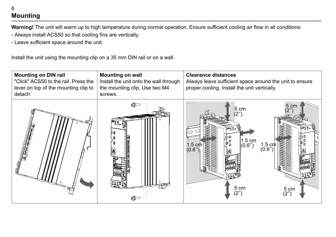
8
oling air flow in all conditions:
snt space around the unit to ensure ll the unit vertically.
1.5 cm (0.6��)
(0.6��)1.5 cm
5 cm5 cm (2��)
5 cm(2��)
5 cm(2��)
(2��)
MountingWarning! The unit will warm up to high temperature during normal operation. Ensure sufficient co- Always install ACS50 so that cooling fins are vertically.- Leave sufficient space around the unit.
Install the unit using the mounting clip on a 35 mm DIN rail or on a wall.
Mounting on DIN rail"Click" ACS50 to the rail. Press the lever on top of the mounting clip to detach.
Mounting on wallInstall the unit onto the wall through the mounting clip. Use two M4 screws.
Clearance distanceAlways leave sufficieproper cooling. Insta
1.5 cm(0.6��)

9
unting clip on the desired side. See
aching the mounting clip, Frame B: h the two parts between the cooling and click them together.
Attaching and detaching the wall mounting clip
The unit can be mounted either with the wide or the narrow side against the wall. Install the mobelow.
Detaching the mounting clip: Press the two plastic buttons to detach the upper and lower part of the clip from each other.
Attaching the mounting clip, Frame A: Place the two parts as shown and click them together.
AttPusfins

10
minutes before adjusting the switches.
eir left position.
Alternative setting 60 Hz
rmal ON - Silent (16 kHz)
mp/fan CT - Constant torque
10 Hz
lt RUN - Motor running
A(0 V) ON - 4 mA(2 V)
autoreset ON - Autoreset enabled
ndard ON - High frequency enabled
DIP switchesDIP switches are used to adapt ACS50 to the motor and the application.
Warning! The DIP switch is at a dangerous voltage (200 V). Turn off power and wait for 5 Keep the protective cover closed when ACS50 is powered.
Configuration� Open the front cover using the tip of a screwdriver, and adjust the DIP switches.� Use the tip of a screwdriver to slide the switch to left or right. As standard, all switches are in th� Close the front cover.
Basic information
DIP switch # Name and function Standardsetting
1 NOM FREQ HZ: Motor nominal frequency 50 Hz
2 SILENT: Motor noise level (PWM switching frequency)
OFF - No(5 kHz)
3 LOAD: Load torque type (U/f curve) P&F - pu
4 JOG HZ: Constant frequency for the jogging function 5 Hz
5 RELAY: Relay output operation FLT - Fau
6 AI OFFSET: Minimum value for analogue input OFF - 0 m
7 AUTORESET: Automatic fault reset function OFF - No
8 HI FREQ: High frequency mode OFF - Sta

11
re electromagnetic pean EMC ACS50
ad. Select P&F for s (e.g. conveyors). tor losses and to
12�24 VDC to digital input 3 ("JOG"). the input is switched off.)
. FLT = Fault. Contact is opened while le running.
0 trips on a fault if the value drops put scaling.
overvoltage, analogue input loss. ximum number of resets is ten in three o Status indications and fault tracing. sure that this will not cause danger.
d by the NOM FREQ HZ switch. ON: REQ potentiometer. See Control
U
f
CT
P&F
fN
UN
10%
Additional information
No. Name Information1 NOM
FREQ HzDefines the motor nominal frequency (see the motor rating plate).
2 SILENT Defines the drive switching frequency. Note: The higher the frequency the monoise and the shorter the allowed motor cable length to comply with the Euroregulations. See Technical data. Note: The switching frequency adapts to thetemperature.
3 LOAD Optimises the output voltage and frequency characteristics according to the lothe squared torque (e.g. pumps and fans) and CT for the constant torque loadACS50 automatically boosts the starting voltage 10% to compensate the moincrease the starting torque.
4 JOG Hz Defines the jogging frequency. Activate the jogging function on by connecting(Drive accelerates or decelerates to the jogging frequency, and keeps it until
5 RELAY Selects the drive state the normally open contact of the relay output indicatesat a fault state or at a power off state. RUN = Running. Contact is closed whi
6 AI OFFSET
Activates a living zero supervision for the analogue input. 4 mA (2 V) = ACS5below the limit. See section Speed controlling for information on analogue in
7 AUTO-RESET
Activates the automatic reset function for the following faults: Undervoltage, ON = ACS50 will try to reset automatically three seconds after a fault trip. Maminutes. If exceeded, ACS50 stops and will not attempt a new reset. See alsWarning! If the start signal is on, the motor will be started after a reset. Make
8 HI FREQ Defines the maximum output frequency. OFF: Max. frequency = value defineMax. frequency = value defined by the NOM FREQ HZ switch + value of HI Fpotentiometers.

12
are in their middle position.
the MOTOR I NOM selection chart easured output current and the
according to the estimation.ight be necessary to increase the
imum frequency and vice versa in follow the given reference.
ency and nominal frequency + 70 Hz. I FREQ DIP switch. See DIP
f. [%]
t
00
ACC/DEC
ACC/DEC time
r nominal current [A]0 nominal current [A]
� 100%
Control potentiometersThe control potentiometers can be adjusted using a screwdriver. As standard, all potentiometers
MOTOR I NOM
Calculate MOTOR I NOM with the equation below or pick a value frombelow. ACS50 estimates the temperature of the motor based on the mdefined motor nominal current. The drive trips if the motor overheats Note: If motor cables are long causing large capacitive currents, it mMOTOR I NOM setting.
ACC/DEC Defines the acceleration and deceleration time from minimum to maxseconds. The longer the ACC/DEC time, the more slowly ACS50 will
HI FREQ Limits the output frequency to a desired value between nominal frequTo use this potentiometer, turn the high frequency mode on with the Hswitches.
Re
1
MOTOR I NOM selection chart
ACS50-01x--01A4-x 0,7 0,8 1,0 1,2 1,4 1,6 1,8 2,0 2,1
-02A2-x 1,11,2 1,4 1,6 1,8 2,0 2,2 2,4 2,6 2,8 3,0 3,23,3
-04A3-x 2,2 2,5 3,0 3,5 4,0 4,3 4,6 5,0 5,5 6,0 6,5
MOTOR I NOM 50 60 70 80 90 100 110 120 130 140150%
motor nominal current (A)
MOTOR I NOM (%) = MotoACS5

13
unit rated for 115 VAC input will damage
n depth for the grounding screws is
er cable, or 75 °C (167 °F) rated cable if and EMC instructions.ording to EN50178 ACS50 may only be
, use IEC269 gG.
N from 200 to 240 V and nominal r equal to the nominal output current (I2)
n is forward, the shaft rotates clockwise
Tightening torque
ore copper wire 0.8 Nm
er wire. Size of the be smaller than the e used.
1 Nm(*)
Connecting power supply and motorWarning! Before installation ensure that the main supply is off.
Note: Ensure power supply is correct! Connecting 230 VAC to the ACS50the drive!
*Note: Use only supplied M4x8 Combi screws. Maximum allowed intrusio6 mm.
Follow local rules for cable cross sections. Use 60 °C (140 °F) rated powambient temperature is above 30 °C (86 °F). See also Additional cabling Earth leakage current of the ACS50 exceeds 3.5 mA AC / 10 mA DC. Accused in permanent installation. Input fuseRecommended fuse types are UL class CC or T. For non-UL installationsMotorThe motor must be a 3-phase AC induction motor, with nominal voltage Ufrequency fN either 50 or 60 Hz. Motor nominal current must be less than oof the drive. If the phases are connected, U-U, V-V and W-W, and the selected directioas seen from the drive shaft end.
Terminal Description Wire size
L/R, N/S 1~ power supply input Max. 2.5 mm2 single c
T1/U, T2/V, T3/W Power output to motor
PE Protective earth.Motor cable protective conductor and shield.
Use multi-strand coppwire is not allowed to size of the power cabl
1-phase input voltage
14
2 wire (AWG22 - AWG16).
me (earth) through 1 Mohm resistor.1.5 kohm.
igital or analogue inputs 1)
igital or analogue input 1)
t: Speed (frequency) reference. (Ri=190 kohm), or 0/4�20 mA . Resolution 0.1%, accuracy +/-1%.
tage for analogue input. %. Max. 10 mA.
ge for digital inputs. Max. 30 mA.
Start (resets the drive after a fault
Reverse rotation direction 2)
Activate jog speed 2)
l cable screen. Connected internally .
pens.12 V...250 VAC / 30 VDC
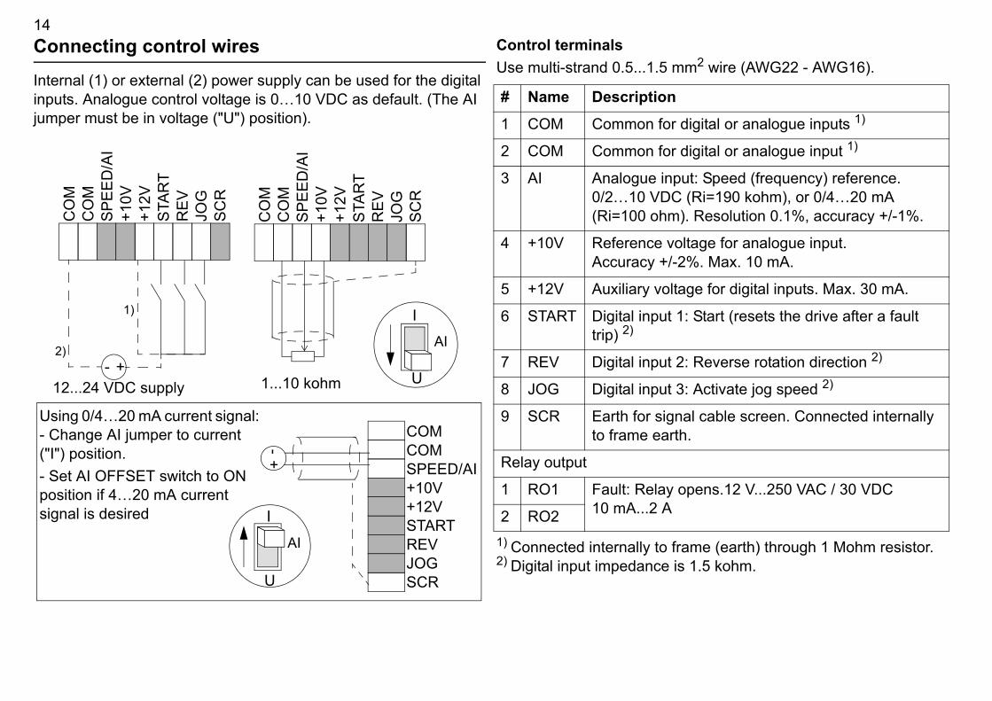
Connecting control wiresInternal (1) or external (2) power supply can be used for the digital inputs. Analogue control voltage is 0�10 VDC as default. (The AI jumper must be in voltage ("U") position).
Control terminalsUse multi-strand 0.5...1.5 mm
1) Connected internally to fra2) Digital input impedance is
Using 0/4�20 mA current signal: - Change AI jumper to current ("I") position.- Set AI OFFSET switch to ON position if 4�20 mA current signal is desired
SCR
STAR
TR
EVJO
G
+-2)
1)
U
I
12...24 VDC supply
+12V
CO
MSP
EED
/AI
+10V
CO
M
SCR
STAR
TR
EVJO
G
+12V
CO
MSP
EED
/AI
+10V
CO
M
AI
U
I
AI
SCR
STARTREVJOG
+12V
COMSPEED/AI+10V
COM
+-
1...10 kohm
# Name Description1 COM Common for d
2 COM Common for d
3 AI Analogue inpu0/2�10 VDC (Ri=100 ohm)
4 +10V Reference volAccuracy +/-2
5 +12V Auxiliary volta
6 START Digital input 1:trip) 2)
7 REV Digital input 2:
8 JOG Digital input 3:
9 SCR Earth for signato frame earth
Relay output
1 RO1 Fault: Relay o10 mA...2 A2 RO2

15
MC directive.
r a four conductor cable with a
Keep the bundle as short as possible.
land or the screen wires must be twisted motor.
clamps
Additional cabling and EMC instructionsFollow these instructions for trouble free operation and to ensure compatibility with European EMotor CableThe motor cable must be a symmetrical three conductor cable with a concentric PE conductor oconcentric shield. Braided metallic screen is recommended. E.g. type MCCMK (NK Cables).- Twist the cable screen wires together into a bundle, and connect to the earthing terminal .- Clamp the cable screen as shown in the figure when internal or external EMC filter is used.- At the motor end the motor cable screens must be earthed 360 degrees with an EMC cable gtogether into a bundle not longer than 5 times its width and connected to the PE terminal of theControl cablesControl cables must be multi-core cables with a braided copper wire screen. A double shielded twisted pair cable is recommended for the analogue signals.- Twist the screen together into a bundle and connect to terminal SCR. Keep the bundle as short as possible.- Clamp the control cable as shown in the figure (EMC units only).- Route the motor cable away from the control wires and the power supply cable to avoid electromagnetic interference (distance > 20 cm).Note: Never mix 24 VDC and 115/230 VAC signals in the same cable.
control cable
motor cable

16
een the analogue input and the the reference changes as defined by
ode ON
tween fN and fN + 70 Hz by the s not affect the scaling of the
w 2 V(4 mA).
Input* V [V, mA]
cy reference
output frequency limit
A
Speed controllingThe analogue input gives the speed (frequency) reference for ACS50. The correspondence betwreference depends on the settings of the DIP switches as shown below. Output frequency followsthe ACC/DEC potentiometer.
High frequency mode OFF (default) High frequency m
DIP switch settings:HI FREQ = OFF AI OFFSET = OFF (curve a) or ON** (curve b) MOTOR NOM FREQ = 50 or 60 Hz
DIP switch settings:HI FREQ = ONAI OFFSET = OFF (curve a) or ON** (curve b) MOTOR NOM FREQ = 50 or 60 Hz
The output frequency is limited to the selected nominal frequency of the motor.
Actual output frequency is limited to a value beHI FREQ potentiometer. The potentiometer doeanalogue input.
* Use AI jumper to select voltage or current signal. See page 14.** To protect the drive against analogue input signal loss, the drive trips if the signal value is belo
f
Input*10 V
fN
[V, mA]0 2 V4 mA
a
b
20 mA
f
100
fN + 70 Hzfrequen
fN
2 V4 mA
ab
20 m

17
tes normally.
ction has been activated. No. of blinks ault code.
set automatically within 3 seconds. (*) r starts, if start signal is on.
what to do less than 4 mA/2 V. (*) Note: This
the AI OFFSET is ON.
rload): 1) Check the load, and verify uitable for ACS50. 2) Verify that setting ntiometer is correct.
essive internal temperature: 1) Load is ling is insufficient.
or. Turn power off and on again. If ce the unit.
Status indications and fault tracing
(*) Automatically reset if the AUTORESET is ON. See DIP switches.
ACS50 has two status indication LEDs, visible through the front cover.If the drive detects a problem, the red LED will blink. After fixing the problem, reset by switching the start signal off. If start is off already, turn it first on and then off again.See the table below for the fault codes (the number of LED blinks).
Green LED Red LED DescriptionOn Off ACS50 opera
On Blinking Protective funindicates the f
Blinking Blinking ACS50 will reWarning! Moto
# Possible causes and what to do # Possible causes and 1 DC overvoltage (*). 1) Mains voltage is too high: Check supply.
2) Deceleration ramp time is too short compared to the load inertia: Increase ACC/DEC time with potentiometer.
6 Analogue input value issupervision is active if
2 DC undervoltage (*). Mains voltage is too low: Check supply. 7 Motor overload (I2t ovethat the motor size is sof MOTOR I NOM pote
3 Output short circuit: Switch off the power and check the motor windings and motor cable.
8 Inverter overload or exctoo high or 2) drive coo
4 Output overcurrent. 1) Acceleration time is too short compared to the load inertia: Increase ACC/DEC time with potentiometer. 2) Motor and drive sizes do not match: Check motor.
9 Other fault. Internal errproblem persists, repla
5 Reserved
OnOff 1 2

18thsC regulations, motor cable length has
he table below. The shorter the motor issions to the supply line and the
e selected with the DIP switch. See
emissions only.and radiated emissions.
er External EMC filter ACS50-IFAB-01 and ACS50-01N/E
6 kHz (1 5 kHz 16 kHz (1
nt, unrestricted distribution (23 m - -3 m - -3 m - -3 m - -3 m - -
nt, restricted distribution (310 m 30 m 10 m10 m 30 m 10 m10 m 30 m 10 m10 m 30 m 10 m10 m 30 m 10 mment (310 m 50 m 10 m10 m 50 m 10 m10 m 75 m 10 m10 m 50 m 10 m10 m 50 m 10 m
Technical data
* Allowed for 1 minute.** Recommended values. Do not use ultra rapid or low peak fuses.
Maximum motor cable lengTo comply with European EMto be limited as specified in tcable, the lower the noise emenvironment.
1) Switching frequency can bpage 11.2) Applicable for conducted 3) Applicable for conducted
230 V 115 VBuilt-in EMC, ACS50-01E-
01A
4-2
02A
2-2
04A
3-2
01A
4-1
02A
2-1
No EMC, ACS50-01N-
01A
4-2
02A
2-2
04A
3-2
01A
4-1
02A
2-1
Motor continuous output power kW 0.18 0.37 0.75 0.18 0.37hp 1/4 1/2 1 1/4 1/2
Frame size A A B A ANominal ratingsInput voltage U1 V 200-240
(+10/-15%)110-120
(+10/-15%)Continuous output current I2 A 1.4 2.2 4.3 1.4 2.2Max. output current I2max* A 2.1 3.3 6.5 2.1 3.3Output voltage U2 V 0-U1,
3-phase0-2xU1, 3-phase
Input current I1 A 4.4 6.9 10.8 6.4 9.5Switching freq. kHz 5 (max. 16)Protection limitsOvercurrent (peak) A 4.4 6.9 13.5 4.4 6.9Overtemperature 95 °C / 203 °F (heat sink)Maximum wire sizesPower terminals mm2 2.5Control terminals mm2 1.5Line fuse size**IEC A 8 12 16 10 16UL A 8 12 20 10 15
Built-in EMC filtACS50-01E-
Converter type
5 kHz 1
EN61800-3, First environme01A4-2 10 m02A2-2 10 m04A3-2 10 m01A4-1 10 m02A2-1 10 mEN61800-3, First environme01A4-2 10 m02A2-2 10 m04A3-2 10 m01A4-1 10 m02A2-1 10 mEN61800-3, Second environ01A4-2 10 m02A2-2 10 m04A3-2 10 m01A4-1 10 m02A2-1 10 m

19
the requirements of the European3/23/EEC with amendmentsEC with amendmentss and a list of main standards are
ibility:wing standards provided that installation ding to the instructions of this manual:
allowed motor cable lengths and 18. See also cabling instructions on
uct of restricted sales distribution class n a domestic environment this product ce in which case the user may be measures.ional equipment to be used in trades, nd which is not intended for sale to authorities shall be notified as ired before connection.
y EN61800-3 first environment, unrestricted / restricted distribution. (1.
EN61800-3 first environment, restricted distribution. (2EN61800-3 second environment
IEC61000-3-2 (3
ProtectionsOvervoltage, undervoltage, output short circuit, overcurrent, analogue input loss, motor overload, inverter overload.
Distribution networks isolated from earthDrives with built-in EMC filter, or ACS50-IFAB-01 external input filter must not be used in a floating network or in a high impedance earthed industrial distribution network.
Environmental informationA product to be disposed contains valuable raw material that should be recycled, thus preserving energy and natural resources. Instructions for disposal are available from ABB sales and service companies.
Liability limitsThe manufacturer is not responsible for:� Any costs resulting from a failure if the installation,
commissioning, repair, alteration or ambient conditions of the drive do not fulfil the requirements specified in the documentation delivered with the unit and other relevant documentation.
� Units subjected to misuse, negligence or accident.� Units comprised of materials provided or designs stipulated by
the purchaser.In no event shall the manufacturer, its suppliers or subcontractors be liable for special, indirect, incidental or consequential damages, losses or penalties.If you have any question concerning your ABB drive, please contact the local distributor or ABB office. The technical data, information and specifications are valid at the time of printing. The manufacturer reserves the right to modifications without prior notice.
Approvals
CE/C-Tick markingThe ACS50 complies with � Low Voltage Directive 7� EMC Directive 89/336/ECorresponding declarationavailable on request.
Electromagnetic compatThe ACS50 fulfils the follois done properly and accor
1) Observe the maximum switching frequency, pagepage 15.2) Warning: This is a prodaccording to EN61800-3. Imay cause radio interferenrequired to take adequate 3) The ACS50 is a professprofessions or industries ageneral public. The supplyauthorisation may be requ
Conductive high frequencemissions
Radiated high frequency emissions
Immunity
Line current harmonics

20
The current harmonic levels can be reduced by fitting external input chokes SACL21/SACL22.UL, cUL and C-Tick markingsSee the rating plate.
AccessoriesEMC filter: ACS50-IFAB-01Input chokes: SACL21, SACL22Output choke: ACS-CHK-B3Potentiometer unit: ACS50-POT