Embed Size (px)
Citation preview

1Low Voltage Installation Guide
Why Landscape Lighting?. . . . . . . . . . . . . . . . . . . . . . . . . . . . . . . . . . . . . 2
Why Low Voltage? . . . . . . . . . . . . . . . . . . . . . . . . . . . . . . . . . . . . . . . . . . 2 Enhancing the Environment . . . . . . . . . . . . . . . . . . . . . . . . . . . . . . . . 3 Creating a Safe Surrounding . . . . . . . . . . . . . . . . . . . . . . . . . . . . . . . 3 Discouraging Intruders . . . . . . . . . . . . . . . . . . . . . . . . . . . . . . . . . . . . 3
What to Light . . . . . . . . . . . . . . . . . . . . . . . . . . . . . . . . . . . . . . . . . . . . . . 4
Which Lamps to Use . . . . . . . . . . . . . . . . . . . . . . . . . . . . . . . . . . . . . . . . 5
How to Light. . . . . . . . . . . . . . . . . . . . . . . . . . . . . . . . . . . . . . . . . . . . . . . . 6 Accent Lighting . . . . . . . . . . . . . . . . . . . . . . . . . . . . . . . . . . . . . . . . . . 6 Area Lighting . . . . . . . . . . . . . . . . . . . . . . . . . . . . . . . . . . . . . . . . . . . 12 Safety & Security Lighting . . . . . . . . . . . . . . . . . . . . . . . . . . . . . . . . . 14
How to Design Your Plan . . . . . . . . . . . . . . . . . . . . . . . . . . . . . . . . . . . 15
Transformers and Cable . . . . . . . . . . . . . . . . . . . . . . . . . . . . . . . . . . . . 18 Multi-tap Transformers. . . . . . . . . . . . . . . . . . . . . . . . . . . . . . . . . . . 22 Designing Cable Runs . . . . . . . . . . . . . . . . . . . . . . . . . . . . . . . . . . . . 23 Calculating Voltage Drop . . . . . . . . . . . . . . . . . . . . . . . . . . . . . . . . . 24
How to Install the System . . . . . . . . . . . . . . . . . . . . . . . . . . . . . . . . . . . 26 Mounting the Transformer. . . . . . . . . . . . . . . . . . . . . . . . . . . . . . . . 26 Hiding the Cable . . . . . . . . . . . . . . . . . . . . . . . . . . . . . . . . . . . . . . . . 26 Installing the Fixtures. . . . . . . . . . . . . . . . . . . . . . . . . . . . . . . . . . . . . 27 Underwater Fixtures. . . . . . . . . . . . . . . . . . . . . . . . . . . . . . . . . . . . . 27 LED Fixtures . . . . . . . . . . . . . . . . . . . . . . . . . . . . . . . . . . . . . . . . . . . 27 Tree Mounted Fixtures. . . . . . . . . . . . . . . . . . . . . . . . . . . . . . . . . . . 27 Moonlighting . . . . . . . . . . . . . . . . . . . . . . . . . . . . . . . . . . . . . . . . . . . 28 Inground Fixtures . . . . . . . . . . . . . . . . . . . . . . . . . . . . . . . . . . . . . . . 29 Inground Installation . . . . . . . . . . . . . . . . . . . . . . . . . . . . . . . . . . . . . 30 Steplyte Installation . . . . . . . . . . . . . . . . . . . . . . . . . . . . . . . . . . . . . . 32 The Quick Connector . . . . . . . . . . . . . . . . . . . . . . . . . . . . . . . . . . . 36
How to Maintain the System . . . . . . . . . . . . . . . . . . . . . . . . . . . . . . . . 36 Cleaning . . . . . . . . . . . . . . . . . . . . . . . . . . . . . . . . . . . . . . . . . . . . . . . 36 Replacing Lamps . . . . . . . . . . . . . . . . . . . . . . . . . . . . . . . . . . . . . . . . 37 Avoiding Corrosion. . . . . . . . . . . . . . . . . . . . . . . . . . . . . . . . . . . . . . 37 Pruning . . . . . . . . . . . . . . . . . . . . . . . . . . . . . . . . . . . . . . . . . . . . . . . . 37
Harsh Environments. . . . . . . . . . . . . . . . . . . . . . . . . . . . . . . . . . . . . . . . 38
Trouble-Shooting . . . . . . . . . . . . . . . . . . . . . . . . . . . . . . . . . . . . . . . . . . 38 Do’s & Don’ts . . . . . . . . . . . . . . . . . . . . . . . . . . . . . . . . . . . . . . . . . . 39
12 Questions You Must Answer in Specifying LEDs . . . . . . . . . . . . . 40
Questionnaire . . . . . . . . . . . . . . . . . . . . . . . . . . . . . . . . . . . . . . . . . . . . . 42
Lamp Charts . . . . . . . . . . . . . . . . . . . . . . . . . . . . . . . . . . . . . . . . . . . 43– 47
Glossary of Terms . . . . . . . . . . . . . . . . . . . . . . . . . . . . . . . . . . . . . . 48– 52
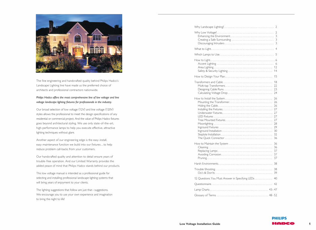
The fine engineering and handcrafted quality behind Philips Hadco’s
Landscape Lighting line have made us the preferred choice of
architects and professional contractors nationwide.
Philips Hadco offers the most comprehensive line of low voltage and line
voltage landscape lighting fixtures for professionals in the industry.
Our broad selection of low voltage (12V) and line voltage (120V)
styles allows the professional to meet the design specifications of any
residential or commercial project. And the value of Philips Hadco fixtures
goes beyond architectural styling. We use only state-of-the-art,
high-performance lamps to help you execute effective, attractive
lighting techniques without glare.
Another aspect of our engineering edge is the easy-install,
easy-maintenance function we build into our fixtures .. . to help
reduce problem call-backs from your customers.
Our handcrafted quality and attention to detail ensure years of
trouble-free operation. And our Limited Warranty provides the
added peace of mind that Philips Hadco stands behind our products.
This low voltage manual is intended as a professional guide for
selecting and installing professional landscape lighting systems that
will bring years of enjoyment to your clients.
The lighting suggestions that follow are just that – suggestions.
We encourage you to use your own experience and imagination
to bring the night to life!

3Low Voltage Installation Guide2 Low Voltage Installation Guide
Why Low Voltage?To give the landscape lighting designer ultimate flexibility, Philips Hadco offers a full line
of low-voltage systems which are safe, affordable, and easy to install.
These systems – which can be installed in a matter of a few hours – reduce the 120-volt
normal electrical line to a harmless and more economical 12-volt system. There is no risk
of injury from electric shock with 12 volts.
And, because the cable for these systems does not need to be buried deep underground,
the process doesn’t entail a lot of tedious work. Junction boxes and other bulky hardware
are not required.
With the use of new, miniaturized lamp technology, low voltage fixtures are smaller
than ever and easier to hide in the landscape.
Enhancing the EnvironmentIn your lighting plan you may want to showcase a particularly attractive aspect of the
client’s property. It may be an interesting piece of art that needs a spotlight, or a flower bed
illuminated. Maybe it’s a pool or lily pond that deserves some added attention. Or you may
just want to enhance the overall beauty of the property. Whatever aspect of the property you
wish to bring to life, Philips Hadco accent lighting will help you beautify the environment.
Creating a Safe SurroundingFeatures like steps, rocks and shrubs can become obstacles or even safety hazards after dark.
Instead of relying on flashlights or blinding floodlights, your clients can install path and step
lighting to ensure safe passage from point A to point B. In fact, any change in elevation
(steps, edges of a deck or terrace, etc.) should be illuminated for safety.
Discouraging IntrudersA well-lit house is the most effective deterrent to potential burglars. However, the glaring
floodlights of the past are not as protective as once thought. Because, while floodlights create
pools of light, they also create pockets of shadow – often close to windows – where thieves
can hide. Philips Hadco fixtures not only beautify the property, but also fill in those areas
of darkness, tastefully directing illumination precisely where it’s needed most.
Why Landscape Lighting?Once upon a time, outdoor activity was ruled by
the sun. Nightfall chased people indoors ... keeping
them there until dawn. Then the development
of outdoor lighting technology began to expand
horizons, giving people more freedom and safety
to enjoy their outdoor environments after dark.
Landscape lighting has grown rapidly ever since,
as emphasis on the environment and escalating
crime rates have created more desire to light up
the night. As a result, professionals have become
increasingly skilled at “extending the day” with
outdoor lighting design.
Lighting landscapes adds elements of beauty,
safety, and security ... in varying combinations,
depending on users’ needs and desires. With today’s advancements in style and
engineering, a well-designed nightscape literally makes two landscapes out of one.

5Low Voltage Installation Guide4 Low Voltage Installation Guide
What to LightTrees. Statues. Pools. Walkways. What features make up your landscape project?
Which elements in an environment should be highlighted, and which should be downplayed?
The answers to those questions will determine the lighting fixtures and techniques
you’ll ultimately use.
Accent lighting is lighting that focuses attention on a particular object or area.
It commands the viewer to take note of a certain subject within the landscape.
Examples of accent lighting are spotlighting a statue, pathlighting a walkway or highlighting
a flower bed with spread lights.
Fill- in lighting is background lighting. It ties the overall landscape picture together,
creating a comfortable transition from one accented area to another. Some examples
may be backlighting a tree, washing a wall or fence, or flooding a row of evergreens
with soft light.
Downlighting may seem more natural because we are accustomed to the light of
the sun and moon. In fact, most of the lighting that occurs naturally in life is from above.
Office lighting, warehouse lighting, sports lighting, and home lighting are all examples
of downlighting techniques. Downlighting is also very efficient in that you get to use
all the light.
Uplighting tends to draw more attention and is often more dramatic. Therefore, it is used
for accent lighting purposes more often than downlighting.
Backlighting is used to silhouette a plant, tree, or structure. Many times the shape
of a plant is more interesting than the detail. By gently lighting a wall or fence behind
the plant, you identify the shape.
Keep in Mind ...Often, it is easier to re-lamp a fixture on the ground rather than one mounted in a tree
or on the soffit of a building. However, fixtures placed high and aimed down are less likely
to be disturbed to need re-aiming. They also do not get covered by leaves, snow, etc.
The decision of which to use is determined by the characteristics and lighting goals of
each individual job.
PAR Lamp
Silicone LensPhosphor Layer
Cathode
TVS
LED Chip
Bond Layer
Metal Interconnect LayerThermal Pad
(electrically isolated)
Ceramic Substrate
MR16 Lamp
Which Lamp / Light Source to UseThe key to any successful landscape lighting design centers around the
lamp. Too much wattage or the wrong beam spread causes unwanted
glare. Not enough light results in an incomplete scene. When it comes
to landscape lighting, a little light goes a long way. The old saying “less is
more” tends to hold true. Consider using lower wattage lamps and more
sources than you would normally use in other lighting applications.
Fixtures that come packaged with general illumination lamps include the lamp that is
usually the best overall choice. Projector type lamps offer a wide variety of choices
to create different lighting effects. The lamp charts in the back of this manual will assist you
in selecting the proper lamp for the desired effect. In most cases you
first choose the lamp and then the correct lamp holder (luminaire).
Keep in mind that all “R”, “MR”, “T3”, and “T-4” lamps require a
luminaire with a lens. “PAR” lamps are designed with their own
tempered glass lens and require no additional protection from
the elements.
PAR36 lamps project light in an oval beam pattern. That is, the horizontal pattern is wider
than the vertical pattern. Aiming is accomplished by looking at the lens. The manufacturer’s
name is written on the horizontal axis (parallel to the widest beam). The double screw
terminal on the back of the lamp is also located on the horizontal axis.
LED lighting is a paradigm shift in the outdoor lighting industry. An LED is a digital solid-state
lighting component that does not need electrical filaments or gas to produce light.
The result is a cool (in the beam),
energy-efficient and reliable
light source that provides
at least 70,000 hours of crisp
white illumination without the
need for lamp maintenance.
7Low Voltage Installation Guide6 Low Voltage Installation Guide
BL5016 AUL1 WAML14
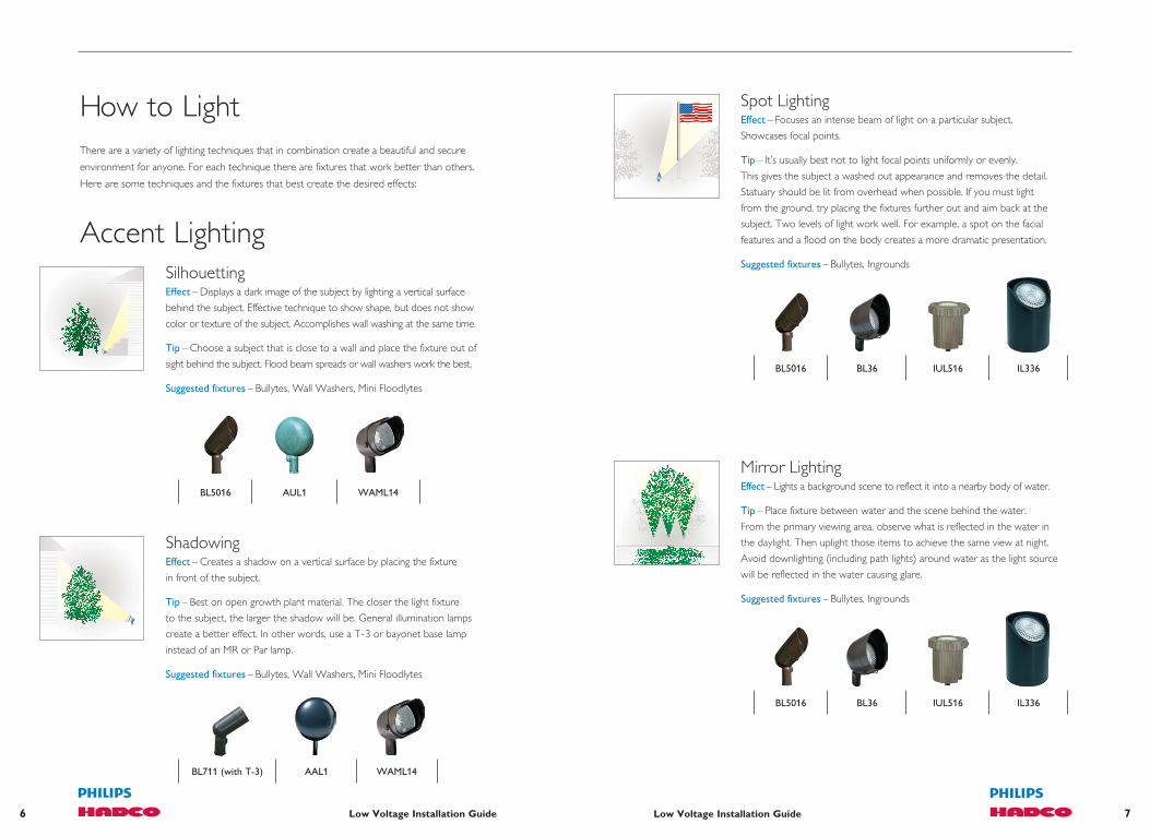
ShadowingEffect – Creates a shadow on a vertical surface by placing the fixture
in front of the subject.
Tip – Best on open growth plant material. The closer the light fixture
to the subject, the larger the shadow will be. General illumination lamps
create a better effect. In other words, use a T-3 or bayonet base lamp
instead of an MR or Par lamp.
Suggested fixtures – Bullytes, Wall Washers, Mini Floodlytes
BL711 (with T-3) AAL1 WAML14
SilhouettingEffect – Displays a dark image of the subject by lighting a vertical surface
behind the subject. Effective technique to show shape, but does not show
color or texture of the subject. Accomplishes wall washing at the same time.
Tip – Choose a subject that is close to a wall and place the fixture out of
sight behind the subject. Flood beam spreads or wall washers work the best.
Suggested fixtures – Bullytes, Wall Washers, Mini Floodlytes
Accent Lighting
Spot LightingEffect – Focuses an intense beam of light on a particular subject.
Showcases focal points.
Tip – It’s usually best not to light focal points uniformly or evenly.
This gives the subject a washed out appearance and removes the detail.
Statuary should be lit from overhead when possible. If you must light
from the ground, try placing the fixtures further out and aim back at the
subject. Two levels of light work well. For example, a spot on the facial
features and a flood on the body creates a more dramatic presentation.
Suggested fixtures – Bullytes, Ingrounds
BL5016 BL36 IUL516 IL336
Mirror LightingEffect – Lights a background scene to reflect it into a nearby body of water.
Tip – Place fixture between water and the scene behind the water.
From the primary viewing area, observe what is reflected in the water in
the daylight. Then uplight those items to achieve the same view at night.
Avoid downlighting (including path lights) around water as the light source
will be reflected in the water causing glare.
Suggested fixtures – Bullytes, Ingrounds
BL5016 BL36 IUL516 IL336
How to LightThere are a variety of lighting techniques that in combination create a beautiful and secure
environment for anyone. For each technique there are fixtures that work better than others.
Here are some techniques and the fixtures that best create the desired effects:

9Low Voltage Installation Guide8 Low Voltage Installation Guide
Wall WashingEffect – Gently illuminates a wall or fence to create a backdrop
for the main focal points.
Tip – Avoid bright spots by positioning the fixtures 18”– 24” away
from the wall.
Suggested fixtures – Wall-washers, Wellytes, Mini Floodlytes
Moon Lighting (Large Trees)Effect – Simulates the light of the full moon filtering through the foliage
of a tree. Projects shadows on the ground. Also lights what is under
the tree (paths, sidewalks, flower beds, etc.).
Tip – Mount with proper tree mount accessory. See section in this
brochure for proper mounting methods. Always run wire or conduit up
the non-viewing side of the trunk. Best mounting height is approximately 20’.
Mount fixtures in open areas of the foliage to avoid hot spots. Aim straight
down as much as possible to prevent glare. Consider composites because
of their light weight.
Suggested fixtures – Bullytes, Mini Floodlytes, Downlytes
BUL16 WAML14 GAHL1 DRL1
Moon Lighting (Small Trees)Effect – Downlighting from within the tree, casting shadows, and lighting
what is under the tree. Best mounting height no more than 10’.
Tip – For use with smaller ornamental trees to cast light around the base
or through the tree.
Suggested fixtures – Downlytes, Micro Bullytes
DL1 DRL1 DSL2 BL756
BL5016 BL36 WAML14
IL116 IL336
GrazingEffect – Enhances texture of a surface by positioning a fixture close
to the surface and aiming the beam upward or downward.
Tip – Try grazing on brick, stone, and stucco walls or any interesting
masonry. Wide floods work best on walls or wide surfaces. Place fixtures
6” to 8” from the surface. When uplighting, put as much light as possible
on the underside of the eave. This will reflect back a good amount of
ambient light, many times sufficient to light sidewalks. Remember to aim
the lamp with the horizontal beam pattern parallel to the wall.
Don’t forget the texture of tree trunks.
Suggested fixtures – Bullytes, Ingrounds, Mini Floodlytes
AAL1 WAML14 IL336

11Low Voltage Installation Guide10 Low Voltage Installation Guide
Tree Lighting (Up and Down)Effect – Combines simulated full moon light filtering through the tree
and uplighting from within to illuminate the canopy. Creates a softer light
on the trunk and keeps all fixtures off the ground.
Tip – Mount downlights on tree mount accessory 15–25’ and use
shrouds and/or louvers to reduce glare. Also consider using spread lens
to widen the beam of the lamp. Mount uplights in the lowest forks of tree
on tree mount accessory. Shrouds and louvers not necessary on uplights.
Use wide beam lamps for all fixtures. Run wire up non-viewing side of trunk.
Suggested fixtures – Bullytes
BUL16 BL1 BL5016
Pond LightingEffect – Illuminates and identifies water in ponds and water features.
Tip – Water should “look” clean enough to drink. Avoid lighting still,
stagnant water with white light. Use colored lenses if water is not clean,
or to create different atmospheric effects. Place light fixtures under
objects or plant material in the water for interesting effects (lily pads,
boulders, art, etc.). For a different approach, light material behind
the pond to create the mirror effect and leave the pond dark.
Suggested fixtures – Underwater
UWL1 UWUL516UWL1075/ UWL1100
Sign LightingEffect – Identifies signage after dark: entrances to sub-divisions,
country clubs, office complexes, and small shopping centers.
Tip – Choose optics that complement the orientation of the sign.
Wide floods for horizontal signs and bullytes or ingrounds for vertical signs.
Suggested fixtures – Bullytes, Mini Floodlytes, Ingrounds
BL36 WAML14
IL116 IL336
BL5016
UplightingEffect – An unnatural, therefore dramatic way of lighting trees and
architectural structures. Highlights details on structures and can be used
to repeat patterns to create interest.
Tip – For dense foliage trees, place the fixtures outside of the drip line
and aim back approximately 45°. Open growth trees can be lit by placing
fixtures closer to the trunk. In all cases, get light to the top of the tree.
Since a lot of light can be lost with uplighting, take care to aim fixtures
so you can recapture the lost light. (Large trees in the background,
peaks of structures, eaves to reflect light back). Look for interesting
details to highlight on architecture.
Suggested fixtures – Bullytes, Mini Floodlytes, Ingrounds
BL5016 WAML14 IL116 IL336

13Low Voltage Installation Guide12 Low Voltage Installation Guide
Spread LightingEffect – Low-level, evenly dispersed illumination to highlight plants,
flowers, low shrubs, and ground cover.
Tip – Place shielded fixtures over low plant material, boulders,
and plant beds. Partially shielded fixtures may be used in deeper foliage
and the additional light will backlight greenery.
Suggested fixtures – Pathlytes, Spreadlytes, Beacons, Underwater
Walkway LightingEffect – Creates symmetrical patterns of light for illuminating walkways,
steps, etc. Used primarily for navigation purposes.
Tip – By lighting only the entrance to a walkway, any turns, and all
changes in elevation, you may avoid the runway look and still accomplish
the task. Placing fixtures near plant material can create shadows
and interest rather than just lighting the hard surface.
Suggested fixtures – Pathlytes, Spreadlytes, Beacons
Area LightingDownlightingEffect – Technique of mounting fixtures in trees or on structures.
Floods will broadcast light over a wide area creating general ambient light.
Spots will dramatically identify focal points. Extremely efficient method of
lighting– which means you can often use fewer fixtures. Very natural looking.
Tip – Look for items of interest on the ground that you want to light,
then look up for places to mount and conceal fixtures. Select proper beam
spreads for what you want to accomplish. Use accessories like spread lenses,
louvers, and shrouds to maximize effects and reduce glare.
Suggested fixtures – Bullytes, Mini Floodlytes, Downlytes
DRL1 DRL2
Fountain LightingEffect – Creates dramatic effects of water movement in fountains
and water features while enhancing the structure of the fountain.
Tip – Water must be clean or moving. In most cases it is better to light
“through” water than “at” water. Allow the water to fall directly on
the fixture. If possible, try lighting tiered bowl fountains from overhead.
Otherwise, each bowl should have a fixture in it. Avoid overlighting and
lighting evenly around the structure as this tends to wash out the detail.
Suggested fixtures – Underwater, Bullytes
UWL1 UWUL516UWL1075/ UWL1100
BL5016 (for downlighting)
CPL21 CUL10 DWCL2
MUL4 GASL4 DWCL1
BL5016 BL36 WAML14

15Low Voltage Installation Guide14 Low Voltage Installation Guide
Step LightingEffect – Lights traffic areas for safety while adding beauty to the steps.
Tip – Every step must be illuminated and visible. Mount fixtures in step
risers, underneath railings, or on vertical posts. All changes in elevation
and terraces should be lit for safety.
Suggested fixtures – Decklytes, Deck Post, Steplytes
RLL1 LLL12
Deck LightingEffect – Illuminates deck floors and steps while enhancing design.
Tip – Consider placing fixtures under built-in benches for a clean,
inconspicuous look. When placing fixtures under handrails,
mount fixtures high enough for good light distribution but be careful
not to see the source when seated. Run cables under the deck
to reduce clutter.
Suggested fixtures – Downlytes, Decklytes, Deck Post
DSL2 DAL1 LLL6
RFL1 AAL1 DSL2
Security LightingEffect – Fills in areas of darkness where intruders could hide.
The right combination of low-level lighting in the landscape will
improve both security and appearance.
Tip – Effective residential security lighting is not prison yard lighting.
The goal is to be able to see movement on the property. This can be
accomplished best with lower levels and more sources rather than
one or two bright sources. Avoid glare.
Suggested fixtures – Bullytes, Mini Floodlytes, Ingrounds, Decklytes,
Steplytes, Pathlytes, Spreadlytes, Beacons
Safety & Security Lighting
DAL1
DL4

17Low Voltage Installation Guide16 Low Voltage Installation Guide
How to Design Your PlanThe Proper Mechanical Design for a Low-Voltage Lighting SystemThere are four components of a low-voltage lighting system that must be selected:
1. Fixtures & Lamps 3. Transformer
2. Mounting Method 4. Cable
1 . The fixtures and lamps are selected after determining which features
of the landscape are to be utilized and what effects you want to create.
When using projector lamps (MR and PAR), the lamp that best creates
the effect should be selected first. To assist in determining the best
choice of lamps, refer to the lamp guide in the back of this manual.
After selection of the lamp, select the fixture according to desired style,
mounting restrictions, and finish from the Philips Hadco catalog.
2. The mounting method is determined by the location of the fixture.
Canopies to allow mounting of fixtures onto decks, non-metallic
stakes for acidic soil conditions, tree-mount canopies and wall plates
are just a few of the options available to you in the accessory section
of the Philips Hadco Landscape Lighting Specification Guide.
3. The transformer is selected by first determining the total wattage
being used in your plan. If more than one transformer is required,
determine the total wattage to be allocated for each. Select a transformer that has a higher
wattage capacity than the actual watts used on that console. We suggest using only
60–80% of the transformer’s capacity since most clients will want to add more fixtures
to the system at a later date. Also, larger wattage lamps are often needed as plants mature.
Remember, your clients only pay for the power actually being used.
Transformers also come in different voltage outputs. Higher output
consoles are used to accommodate longer cable runs. Refer to
pages 19–22 to determine which transformer is right for your job.
The mounting location of the transformer must also be considered.
In some cases, you might want to consider an inground model to
better conceal it.
4. The correct cable needed for your job is determined by the length of the runs and
the amount of wattage per run. Refer to the voltage formula on page 27 to assist you
in selecting the proper gauge and length of cable. When laying out a job, always center
feed to the group of fixtures on any single run. Avoid wiring to the closest fixture and
continuing out from there in a straight line. Also, avoid heavily loading any single run.
Keep run as short as possible.
The layout itself can be accomplished by sketching a view of the property, including all
landscape features to be illuminated. Mark the location of each fixture and transformer.
Draw a dotted line from the power console to each fixture to denote the cable,
remembering to center feed each group of fixtures. Try to avoid running the cable
under walks and drives more than once to help eliminate the need for extra work
when installing. Keep a copy of the plan as a reference for expansion or excavation work.

19Low Voltage Installation Guide18 Low Voltage Installation Guide
15 Volt Standard Transformers (TC-15 Series)
•12, 13, 14, and 15 volt outputs
•Polyester powdercoated steel case
•ETL and cETL listed for outdoor or indoor use
•10-year warranty
When to Use: Perfect for indoor use (garage, basement, out-building). Suggested
for outdoor use when painting the transformer the same color as the structure it is
mounted to. Multi-taps of 12 –15 volts for short to average length runs. 150 watt model
(12 volt output only) ideal for small areas with just a few fixtures.
Features:
•Epoxy encapsulated toridal transformer with built-in primary thermal protection
•Removable, gasketed hinged door
•Weatherproof compartment for plug-in time clock (T5 or T6 sold separately)
•Plug-in photocell (PC3 or PC15, sold separately)
•1/2” knockout for photocell mounting
•Four to eight double knockouts for 1/2” or 3/4” conduit
•One 1 1/2” conduit inlet
•Hinged bottom plate
•Large wiring compartment
•Large terminal blocks
•X-10 compatible
•Magnetic circuit breaker for each 300 watt secondary circuit
•6 ft. grounded cord and plug
Cat. Number Capacity Output
TSS344 -15 300 watt 12, 13, 14, 15 Volts
TSS644 -15 600 watt 12, 13, 14, 15 Volts
TSS944 -15 900 watt 12, 13, 14, 15 Volts
Cat. Number Capacity Output
TC151-12 150 watt 12 Volts
TC151-12TP 150 watt 12 Volts
TC344-15 300 watt 12, 13, 14, 15 Volts
TC644-15 600 watt 12, 13, 14, 15 Volts
TC944-15 900 watt 12, 13, 14, 15 Volts
Transformers and Cable“The Lifeline to Landscape Lighting” The transformer and cable system of a lighting plan can be compared to a human
circulatory system. The transformer is the heart of the whole operation, “pumping”
out energy to the extremities (light fixtures). Transformers come in various sizes or
load capacities. Philips Hadco offers both above ground and inground versions in a variety
of wattage capacities and power outputs. The following two pages are a guide in
choosing the transformer that is right for your client’s system.
15 Volt Stainless Steel Transformers (TSS-15 Series)
•12, 13, 14, and 15 volt outputs
•Brushed stainless steel case
•ETL and cETL listed for outdoor or indoor use
•Lifetime warranty
When to Use: Ideal for outdoor use in any environmental conditions.
Wall or post mount. Multi-taps of 12 –15 volts for short to average length runs.
Features:
•Epoxy encapsulated toridal transformer with built-in primary thermal protection
•Removable, gasketed hinged door
•Weatherproof compartment for plug-in time clock (Except TC151-12. T5 or T6 sold separately.)
•Plug-in photocell (Except TC151-12. PC3 or PC15, sold separately.)
•1/2” knockout for photocell mounting
•Four to eight double knockouts for 1/2” or 3/4” conduit
•One 1 1/2” conduit inlet
•Hinged bottom plate
•Large wiring compartment
•Large terminal blocks
•X-10 compatible
•Magnetic circuit breaker for each 300 watt secondary circuit
•6 ft. grounded cord and plug
•TC151-12TP features built-in 24 hour time clock and factory installed photo cell

21Low Voltage Installation Guide20 Low Voltage Installation Guide
22 Volt Stainless Steel Transformers (TSS-22 Series)
•12, 13, 14, 15, 17, 20, and 22 volt outputs
•Brushed stainless steel case
•ETL and cETL listed for outdoor or indoor use
•Lifetime warranty
When to Use: Ideal for outdoor use in any environmental conditions.
Wall or post mount. Multi-taps up to 22 volts for extra long runs.
1200 watt total maximum capacity.
Features:
Cat. Number Capacity Output
TSS683-22 600 watt 12, 13, 14, 15, 17, 20, 22 Volts
TSS983-22 900 watt 12, 13, 14, 15, 17, 20, 22 Volts
TSS1283-22 1200 watt 12, 13, 14, 15, 17, 20, 22 Volts
• Epoxy encapsulated toridal transformer with built-in primary thermal protection
•Removable, gasketed hinged door
•Weatherproof compartment for plug-in time clock (T5 or T6 sold separately)
•Plug-in photocell (PC3 or PC15, sold separately)
•1/2” knockout for photocell mounting
•Four to eight double knockouts for 1/2” or 3/4” conduit
•One 1 1/2” conduit inlet
•Hinged bottom plate
•Large wiring compartment
•Large terminal blocks
•X-10 compatible
•Magnetic circuit breaker for each 300 watt secondary circuit
•6 ft. grounded cord and plug
Inground (TBC-15 Series)
•Inground installation (flush to grade)
•Hardwire 12, 13, 14, and 15 volt leads
•ETL and cETL listed
•10-year warranty
When to Use: Applications where there is no where to “hide” a transformer.
(Patio/courtyard areas, plant islands, center of circle drives, etc.)
Features:
Cat. Number Capacity Output
TBC303-15 300 watt 12, 13, 14, 15 Volts
TBC603-15 600 watt 12, 13, 14, 15 Volts
•Fiberglass reinforced composite box with composite lid and silicone gasketing
•Separate wiring compartment with two 3/4” inlets
•Epoxy encapsulated toroidal transformer with built-in primary thermal protection
•Magnetic circuit breaker for each 300 watt secondary circuit
•Shielding between primary and secondary circuits
•Multiple 1/2” knockouts on bottom of box
•Waterproof connectors for low voltage cable outlet; one supplied with 300 watt unit, two supplied with 600 watt unit
•Potting compound supplied for line voltage compartment

23Low Voltage Installation Guide22 Low Voltage Installation Guide
Multi-tap TransformersOnce you have selected the size transformer needed for your installation, you will have a choice
of voltage outputs to use. Philips Hadco offers two models with different maximum voltage
outputs. One transformer model offers a 12, 13, 14, and 15 volt terminal on the terminal strip.
Another model offers a 12, 13, 14, 15, 17, 20, and 22 volt terminal on the terminal strip.
These higher voltage output transformers are used to accommodate longer cable runs.
All terminal strips also have common terminals. Since all cable is two conductor, one conductor
is connected to the common terminal and the other conductor is connected to the voltage
output of your choice. More than one cable run can be connected to any one terminal;
however, a maximum of 300 watts is allowed per common terminal.
Each common terminal is protected by a magnetic circuit breaker that will trip if the common
terminal is overloaded. The breaker will also trip if a dead short occurs on a cable run.
Transformers are equipped with a breaker for each common terminal, therefore, a 300 watt
transformer has one common and one breaker; a 600 watt has two commons and two breakers;
and so on. On inground transformers you will find wires marked with the above voltages
to hard wire to your cable.
Philips Hadco manufactures its transformers to carry the full load for which they are rated.
In other words, a 600VA transformer will carry up to 600 watts of light. However, when initially
installing a transformer on a new project, we suggest that only 60–80% of the capacity be used
in case you want to add more fixtures later or need to increase lamp wattages.
SwitchingAll Philips Hadco transformers are equipped for easy-to-use plug-in type photocells and/or
time clocks. Remember that photo cells alone are going to burn the lamps all night, shortening
lamp life. Time clocks might need to be re-set occasionally to compensate for changing seasons.
Using both might be the best option. Set the timer to come on at 4 p.m. every day.
Since the photocell is wired after the timer, the lights will not come on until dark. Set the timer
to go off at midnight, 1 a.m. or whatever your client prefers. This method burns lamps only
when it’s dark and during the hours the client needs them. All Philips Hadco transformers
(except TC151 ) will accept X-10 PRO switching modules.
Amp ProbeIt is important to check each transformer with an amp probe on both the primary and
secondary side to ensure that maximum amp draws are not exceeded. Transformers are
equipped with an amp probe loop (primary) and the loop is labeled with a maximum
allowable amp draw. Each cable run to the fixtures (secondary) should not exceed 25 amps.
(See installation instructions with transformer.)
Designing Cable RunsAVOID STRAIGHT RUNS, end fed with the wire going to the closest fixture first.
This type of run feeds most of the voltage to the first lamp. The remaining lamps receive
progressively less and less voltage, so the line is not in balance.
Only do this up to two fixtures. Three or more, go to center feed.
Center Fed “T” RunsThese work the best.
•3–5fixtureperrun.
•Maximum 180 watts per run on 12 gauge wire.
•Centerfeedtotheloadoftherun.
•Max.25’from“T”connectiontoanyfixture.
This delivers almost equal voltage to all fixtures resulting in equal brightness
and prolonging lamp life.
From the above calculations and examples it becomes obvious that properly designed
systems require the use of more wire. Just like a properly designed sprinkler system,
it is necessary to equalize the delivery of water (electricity) to each sprinkler head (lamp).
Keep in mind that wire is the least expensive component of a system.
Max. 180 watts total on 12 gauge wire

25Low Voltage Installation Guide24 Low Voltage Installation Guide
Wire Size Cable Constant
#18 1380
#16 2200
#14 3500
#12 7500
#10 11920
#8 18960
18 GAWire
12 GAWire
vs.
Voltage at lamp is determined by subtracting voltage drop from voltage at the transformer.
The voltage at the transformer will change depending upon:
1. Which voltage tap is used (12, 13, 14, 15, 17, 20, or 22V).
2. The total load on the transformer.
3. The voltage feed to the transformer.
Voltage drop to the lamps can be controlled by:
1. Using the proper voltage tap on the transformer.
2. Center feeding to the load of each run.
3. Using proper cable size.
4. Using fewer fixtures on a cable run.
5. Using lower wattage lamps.
Any of these methods can be used in conjunction with each other.
The simplest and easiest way to lay out your wire runs is to connect all cables and fixtures,
leaving the cable above ground. Mark each run at each end with colored or numbered tapes.
Connect all runs to the 12 volt tap. (You may have to do these a few at a time.)
Take a voltage meter reading at the fixtures at the point of center feed. Whatever the
reading is, note the difference, go back to the transformer and connect that run to the tap
that will deliver 11.5 volts. If you have followed all the recommendations above and following,
all other lamps should be receiving a minimum of 10.8 volts, but check them all just to be sure.
NOTE: For exceptionally long runs, you can use larger gauge wire for the main leg.
Calculating Voltage DropVoltage drop on the lighting system will effect the lamp life and the amount of light the
lamps will deliver. Too much voltage drop lowers the light output and changes the color
of the light from white to yellow or orange. Too little voltage drop burns the lamps,
too hot and shortens lamp life.
The following table shows the effect of voltage drop for standard non-halogen lamps.
A lamp with a design voltage of 12V will deliver 80% of its light output and its life will
double by reducing the voltage .5V. The light loss is hardly noticeable to the naked eye
while the lamp life is greatly extended. Therefore, in the outdoor environment,
we want to design for a slight voltage drop to all lamps.
The recommended voltage to each lamp is 10.8V–11.5V
Remember, with halogen lamps such as the MR-16 a voltage feed of less than 10.8V
may adversely affect the lamp. (Halogen cycle).
Total Watts – Sum of wattage for every lamp on one piece of cable.
Cable Length – Length of cable used (feet) from transformer to fixture for which you
are calculating voltage drop.
Cable Constant – Indicates thickness of copper wire. The thicker the wire, the lower
the conduction resistance and the lower the voltage drop.
Voltage Light Output Lamp Life
12.5 170% 80%
12.0 100% 100%
11.5 80% 200%
11.0 75% 300%
10.5 65% 500%
10.0 50% 900%
Total Watts x Cable Length
Cable Constant(x 2) = Voltage Drop

27Low Voltage Installation Guide26 Low Voltage Installation Guide
How to Install the SystemThe next step is the installation itself. Philips Hadco Landscape fixtures are designed
to make installation as quick and simple as possible. And one of the benefits of low voltage
lighting is its flexibility, so you don’t have to be absolutely sure about the placement
of fixtures the first time.
If you’re dealing with new property, there are several steps that, done in advance,
will make installing a lighting system later much easier.
Pre-planning Tips for a New Property1. Install extra switches by exterior doors.
2. Consider transformer locations and provide easy access to power at these locations by installing outlets now.
3. Place conduit under sidewalks and driveways before they are installed so wire can be easily run underneath.
Mounting the TransformerMount the transformer next to a grounded indoor or outdoor outlet. If
the transformer is installed outside, mount it at least one foot above the
ground. It can be mounted on a wall, fence, post, etc. Follow the specific
installation instructions provided with your transformer.
Hiding the CableNext, lay the cable out on top of the ground in the configurations needed to reach every
fixture. Then, connect all the fixtures. Test the voltage at each fixture with your volt meter.
This allows for easy adjustments to the cable runs while they are still above ground.
Then, you might want to wait until dusk to visually adjust the fixtures to achieve maximum
effect. After these steps the cable can be buried.
Because you are working with low voltage, hiding the cable is very simple. You may choose
to cover it with some soil, mulch or other landscape dressing. Or if you are close to bushes
or dense shrubbery, you can push it underneath and out of sight. You could also lay it
along a fence or foundation nearby.
If you are crossing a lawn, you will want to slice the sod at a 45° angle. Pull up the sod,
place the cable at least 4’ deep (to prevent future problems if the lawn is aerated)
and replace the sod firmly.
Installing the FixturesEach fixture is packaged with installation instructions that will tell you step-by-step how to
properly install your system. Refer to those instructions for specific requirements. The following
sections were designed to supplement the instructions for fixtures that need extra care.
Underwater FixturesPhilips Hadco underwater fixtures are designed to enhance the natural beauty
of a fountain, reflecting pool, or fish pond. The fixture is composite-molded
with a watertight seal around its lens. The materials used to construct our
underwater fixtures will not oxidize over time as copper and brass would.
Never use brass or copper for underwater lighting. The corrosion of these
metals can harm aquatic plant and animal life.
LED FixturesAll of our low voltage LED products are installed the same as our other low voltage products with
the following caution. Our LED fixtures have built-in drivers that regulate the voltage to the LED’s.
However, the built-in driver in each of our low voltage fixtures will only function properly if the incoming AC
voltage is between 10.8 and 17.5 volts. If the voltage exceeds 17.5 volts at the fixture, the capacitors may
burn out prematurely. Capacitor burn out voids any warranty offered with this fixture. It is necessary
therefore to use a voltmeter to ensure that the voltage at the point of installation is within the range
specified. When using a 22-volt terminal for long run application one must be careful to ensure
the voltage has dropped to 17.5 volts before installing an LED product. Installation of an LED fixture
on a line that falls below 10.8 volts may allow the unit to still function with lower lumen expression
or it may not light up at all, but voltage that is lower than 10.8 will not damage or shorten the life of
our LED products. Finally, if your installation requires the use of an electronic transformer, the voltage
range stays the same, but you must use an electronic transformer that runs at 60Hz. Failure to use
a 60Hz electronic transformer will strobe the LED’s and destroy the unit in a short period of time.
Tree Mounted Fixtures It is a special situation when you think about mounting fixtures in a tree. Unlike soil and cement,
trees are living things and require special attention.
The first thing to consider is that lamps in the fixtures will have to be
replaced periodically. This means someone will have to climb up into
the tree every so often to take out the old lamp and put in the new
one. Make sure you have a way of maintaining the fixtures before
you install them.

29Low Voltage Installation Guide28 Low Voltage Installation Guide
Tree Type Lighting Techniques
Conifer (conical evergreen)
The foliage is dense and narrow. Place the fixture(s) away from the base and aim light toward the top of the tree.
Flowering Deciduous (Dogwood, Fruit, etc.)
As the Conifers, place the fixture(s) away from the base and aim toward the top. Their beauty is at the tips of their branches where blossoms and fruit grow.
Deciduous, Dense Canopy (Oak, Maple, Chestnut, etc)
Place fixture(s) along the outer edges to focus light into the foliage. These trees have interesting bark and elaborate branch structures. Use more than one fixture to highlight these areas.
Deciduous, Open Canopy (Birch, Walnut & Palm)
These open canopies and palms can be grazed with light from underneath. Place the fixture(s) close to the base of the tree.
Inground FixturesIngrounds require some extra attention, and should be used primarily where they
will remain permanently (e.g. to light buildings, fences, mature trees, flag poles, etc.).
However, when installing an inground beneath a tree, do not forget
cutting into the roots may severely damage the tree, or even kill it.
Try to use fixtures that are less than 12 inches deep for tree uplighting
when placing the fixture under the canopy of the tree.
Another consideration to make with ingrounds
is drainage capability. Because the fixtures are
inground, there is always the problem of moisture. Provide a minimum
3˝ drainage bed of granular material as recommended in the packaged
instructions. Sealing the fixture as recommended in the packaged
instructions will help ensure warranty coverage.
The second consideration is the means of fastening the fixtures. You must use fasteners
that are constructed of stainless steel or cadmium-plated steel. Never use brass or copper
fasteners in a tree. Brass and copper oxidize over time, poisoning the tree. Your fasteners
should also be adjustable to allow for growth, upward and outward. We suggest using the
MF -1 combination lag screw to secure the mounting canopy. The supply cable should be
attached to the tree trunk with nylon cable ties that are screwed to the tree to allow for growth.
Care should be taken when aiming the fixtures to eliminate direct glare from the lamp
and the long directional shrouds should always be used. Consider that the tree will lose its
leaves in the fall. Since trees come in all different shapes and sizes, there are several ways
to enhance them. You will not want to light an evergreen the same way you light a chestnut.
Here are some tips for lighting various types of trees from the ground:
MoonlightingOne of the most beautiful–and most difficult– landscape lighting
techniques, moonlighting simulates the natural light of a full moon
filtering through the branches of a tree.
When creating the moonlighting effect, remember to place one
or two fixtures above eye level aimed upward to illuminate the top
of the tree’s canopy. The number of fixtures placed in the downlighting position is dependent
upon the physical size of the tree as well as the density of its foliage.
The following chart is a guide in determining the number of fixtures to use. The actual
number may vary with personal taste.
To use the chart, determine the approximate canopy size of the tree being illuminated
by multiplying the total width (x) and height (y) of the
tree in feet. Use a corresponding number in the chart
to determine the number of fixtures for your tree.
For applications where a single fixture is suggested,
place the fixture on the trunk in an uplighting position.
CAUTION: Use only stainless steel fasteners when
mounting fixtures on trees. Brass or copper can harm
the tree over time.
Canopy Size Width x Height Foliage Density
0–50Heavy
Light
2
1
50–150Heavy
Light
3
2
150–300Heavy
Light
4
3
300–500Heavy
Light
5
4
500–750Heavy
Light
6
5
750–1200Heavy
Light
7
6
1200–1800Heavy
Light
8
7
35 watt MR16 or PAR36
x
y

31Low Voltage Installation Guide30 Low Voltage Installation Guide
Ground Installation (IUL516 Shown)
NOTE: Do not place fixture in a below-grade location as the fixture will collect dirt and debris, and possibly become submerged in extremely wet conditions. Do not place plantings too close to the fixture as the foliage may grow over the luminaire, blocking the light. Do not allow mulch to touch inground fixture in any way as this may cause the fixture to overheat and fail.
1. Excavate soil for fixture placement and conduit runs, making sure the fixture will be
elevated and the grade sloped down from the fixture. Be certain to allow a minimum
of 3˝ of drainage material (sand or gravel only) under and around the housing.
2. Remove trim ring and lens and install specified lamp. Replace trim ring.
3. After drainage material is installed in the bottom, place fixture housing into hole,
back-filling a minimum of 3” of drainage material (sand or gravel only) around the side
of the housing. Be certain that the underside of housing flange rests on top of grade level.
4. Connect low voltage fixture wire to low voltage cable running to remote transformer,
using silicone wire nuts or quick connector (supplied).
5. Turn power on at transformer.
Low Voltage Installation Guide
Concrete
DrainageGravel
(3” minimum)
1
2
3 4
5
67
8
Order in which to tighten screws
Inground InstallationConcrete Installation (IL116 Shown)
NOTE: To ensure proper drainage, prepare gravel foundation. Make certain that the concrete level, when poured, will be flush with the top of the concrete pour accessory. To help decrease condensation, energize fixture for 20 minutes prior to installing and tightening main lens and retainer.
1. Remove trim ring and lens and install specified lamp. Replace trim ring and lens.
2. Position the fixture housing into the concrete pour accessory, making sure that the
underside of the housing flange rests on top of the set screws. Tighten set screws
on side of accessory to lock the housing into place (do not over-tighten).
Secure assembly to the final location with re-bar or other anchoring device.
3. Excavate soil where the fixture is to be installed.
4. Place assembly into excavated opening. Be sure there is a minimum of 3” of drainage
material (sand or gravel only) covering the bottom of the hole.
5. Fill area with a minimum of 3” of drainage material. Be sure not to fill area flush with top
of frame and assembly. This is to be filled with concrete.
6. Connect low voltage fixture wire to low voltage cable running to remote transformer,
using silicone wire nuts or quick connector (supplied).
7. Pour concrete. Remember that fixture position cannot be altered after the concrete sets.
8. Turn power on at transformer.
Low Voltage Installation Guide

33Low Voltage Installation Guide32 Low Voltage Installation Guide
Installation for New Stud Wall (Use Accessory Kit #MAKNS)
1. Using the supplied template, cut a level hole through the existing wall between studs. (Failure to level hole will cause fixture to have tilted appearance.)
2. Mount L-brackets onto top and bottom of housing with screws positioned in center of slots.
3. Insert cross brackets through L-brackets.
4. Position fixture so the back of the finishing ring extends past the studs the thickness of the wallboard.
5. Level fixture and hammer tabs on cross brackets into studs. Nail brackets securely to studs.
6. Fine adjust fixture position and tighten any loose screws.
7. Remove the 1/2” NPT plugs from the sides/bottom of the housing and pull the supply wire through into the housing. (Through wiring not recommended.)
8. Remove finishing ring by removing flathead screws.
9. Install wallboard.
10. Replace finishing ring.
11. Install thermal protector (attached to electrical chassis).
Installation for Existing Stud Wall (Use Accessory Kit #MAKES)
1. Using the supplied template, cut a level hole through the existing wall between studs. (Failure to level hole will cause fixture to have tilted appearance.)
2. Push the four (4) mounting screws through the housing holes and into rear channels. (Note: a thin membrane covers the housing holes and may require forcing the screws through by tapping them lightly with a hammer.)
3. Place flags flat on rear of housing. Thread screws into and through the flags.
4. Remove the 1/2” NPT plugs from the sides/bottom of the housing and pull the supply wire through into the housing.
5. Push housing into the hole in the wall.
6. Tighten the mounting screws until the flag fasteners are drawn tight against the inner surface of the wall.
7. Install thermal protector (attached to electrical chassis).
Steplyte Installation

35Low Voltage Installation Guide34 Low Voltage Installation Guide
Installation for Masonry (Use Accessory Kit #MAKM)
1. Install screw through washer and lower masonry brackets and into tapped housing
hole on bottom of fixture.
2. Remove the 1/2” NPT plugs from the sides/bottom of the housing and pull the supply
wire through into the housing.
3. Press fixture and lower masonry brackets into layer of mortar so that mortar comes
through the holes of the brackets.
4. After laying another course of blocks, install the two upper masonry brackets
onto the housing as in Step 1.
Installation for Concrete Pour (Hardware included with each fixture)
1. Level supplied template on wood support frame and drill four (4) 3/16” diameter
clearance holes as marked.
2. Remove the 1/2” NPT plugs from the sides/bottom of the housing and pull
the supply wire through into the housing.
3. Install plastic protective shield (if supplied) into housing and make sure all unused
electrical plugs are replaced.
4. Finishing ring may be removed now and replaced after concrete pour.
5. Secure housing to wood support with screws supplied in hardware packet.
6. Pour concrete.
7. If finishing ring was removed, replace it and tighten flathead screws.
If screws are not tight, fixture may leak.
Steplyte Installation

37Low Voltage Installation Guide36 Low Voltage Installation Guide
The Quick ConnectorFor your convenience, Philips Hadco low voltage fixtures are provided
with a Quick Connector. The Quick Connector accepts single circuit wire
from 10–14 gauge. The unique connector also makes it easy to fasten a
fixture to the power cable and is flexible enough to move the fixtures as
the landscape changes.
Approved for direct burial, the Quick Connector can be directly covered
with any landscape dressing material. However, when in contact with
wet or constantly moist conditions, we recommend that you seal the
connector with mastic or silicone caulking after checking to make sure
the connection is sound. Turn the transformer on when installing
fixtures to ensure good contact with the Quick Connector.
NOTE: If you prefer the hard-wire method (stripping the cable and splicing the wires),
you still have the flexibility of the 3-foot power cord Philips Hadco supplies with each fixture.
Installation Tips • Energize the low voltage cable when installing fixtures with Quick Connectors to ensure
proper connection. (Power should be off when hard wiring fixtures)
• Check electrical connections, voltage drop, and aiming of fixtures before burying cable.
• Dip lamp bases in corrosion preventive compound or spray with silicone to help
prevent oxidation.
• To prevent a short circuit, double-check end of cable to ensure there are no ragged
strands of copper touching another circuit lead.
• Seal and tape end of cable to stop voltage draw due to oxidation of the copper.
• In damp or wet areas, seal connectors with mastic or tub caulking to keep out moisture.
How to Maintain the SystemCleaningAs with any system, an occasional cleaning will ensure longevity and consistent performance.
Periodically, remove dirt, leaves and other debris which tend to collect around the fixtures.
A clean lens helps the lamp to operate more efficiently, extending lamp life. Pay particular
attention to inground fixtures and fixtures in low lying areas. When tackling the cleaning
of fixtures, consider moving them to create a different look.
Replacing LampsDifferent lamps have different life expectancies. This means someone will occasionally
need to replace lamps in the fixtures.
The following chart represents the average life expectancies (in hours) for low voltage
incandescent, halogen and LED lamps:
Average lamp life hours are based upon the lamp receiving its full design voltage
(usually 12V). Remember that reducing the voltage slightly will extend lamp life.
To convert to days, simply determine the number of hours the system will be operated
daily and divide into the above hours.
Avoiding CorrosionWhen installing lamps, dip the lamp bases into corrosion preventive compound or spray
sockets with silicone to help prevent oxidation between the lamp and its socket. Repeating
this application once a year also provides a better connection between the lamp and socket.
Also remember to seal and tape exposed wire to slow oxidation of the copper.
Use mastic, or caulking—whichever is appropriate in your situation.
PruningSince you are working with living and growing things, your client will need to prune
periodically to keep the fixtures from disappearing into an overgrowth of shrubbery.
Don’t forget to reposition fixtures – especially in trees – to cover any bright spots.
Incandescent, Halogen and LED Lamps
Lam
p L
ife I
n H
ou
rs
60000
50000
40000
30000
20000
10000
0 1141 1156 MR11 MR16 PAR36 T3 T4 LED Xenon
1000 1500 3500 4000 5000 2000 2000
50000
10000

39Low Voltage Installation Guide38 Low Voltage Installation Guide
Harsh EnvironmentsSome environmental conditions require special consideration when choosing your
Philips Hadco fixtures. Such environments include:
• Water or air with a high salt content (coastal areas)
• Soil with a high acid content
• Soil that is heavily fertilized
For these environments, we strongly recommend you consider Philips Hadco’s
NON-METALLIC (composite) or solid cast brass fixtures. These fixtures are designed
to hold up to the test of harsh environments. You may want to look into Philips Hadco’s
inground fixtures with composite housing. And if you are in the market for architecturally
styled spotlights, you have the option of Non-Metallic Bullytes, which replace the
unattractive floodlights of the past. Call your local dealer for specific fixtures.
DON’T FORGET. . .
The environment is ever-changing, so landscape lighting requires periodic attention.
Careful maintenance will help prolong the life of the system.
Trouble-shootingSystem Problems
Entire system will not operate
1. Check 120 volt outlet to ensure you have power to the outlet.
2. Check the timer switch on transformer to be sure it’s on.
3. Check or re-set circuit breakers on transformer.
4. Check low voltage cable connection at transformer.
5. Check photo cell.
Circuit breaker on power console trips
1. Check end of cable to ensure copper strands are not touching.
2. Check connection of cable at power console to ensure copper strands are not touching.
3. Recalculate total wattage to ensure that you have not exceeded rated wattage
of transformer.
4. Check for other “shorts” at fixture connection points.
Fixture Problems
Fixture will not light
1. Check lamp for broken filament.
2. Check lamp for proper fit in socket.
3. Check connector to cable to ensure that pins have pierced insulation into copper strand.
Fixture has moisture build-up inside
1. Check to ensure that shrouds and lens rings are installed properly.
2. Check that gaskets are clean and free of debris between gasket and housing.
3. Check drainage holes for blockage.
4. Check water-tight fittings on inground fixtures.
5. Refer to installation instructions for exact fixture.
Fixture is on, but dim
1. Check voltage at fixture with volt meter to ensure it’s receiving a minimum of 10.8V.
2. Check total wattage calculation. Use lower wattage lamps, remove one or two fixtures
from circuit or connect to higher voltage terminal.
DoDo Use More Fixtures and Less WattageIt’s important to place the light exactly where you want it. This is better accomplished
by using small wattage sources aimed directly at the subject rather than using a higher wattage
source in hopes of washing light over the subject.
Do Hide the Source of Light Glare is one of the evils of light. Use shrouds, louvers, and natural obstructions such as rocks,
shrubs, etc. to hide the source of light. Consider viewing angles and aim away from them.
Don’tDon’t OverlampOverlighting is the most common mistake made in landscape lighting. Too much light
will wash out the landscape. Remember, a full moon only produces 1–2 one-hundredths
of a footcandle of light. More fixtures at a lower wattage will create a more natural effect
than a few bright lamps.
Don’t Put Fixtures in the WayConsider lawn maintenance and pedestrian traffic.

41Low Voltage Installation Guide40 Low Voltage Installation Guide
12 Questions You Must Answer in Specifying LEDs1. Is your LED supplier a reliable company?
Philips Hadco only uses products from top LED suppliers in the industry including Philips Lumileds,
Nichia, and Cree. These suppliers have been manufacturing LEDs and the phosphors used in them
for many years and they guarantee quality, reliability, and IP.
2. Has your supplier provided an IESNA LM-80 test report?
All LED suppliers used by Philips Hadco provide IESNA LM-80 test reports when available.
For legacy LEDs that preceded IESNA LM-80, our suppliers provide test reports that are equivalent
to or more stringent than IESNA LM-80 requirements, and they are in the process of obtaining
IESNA LM-80 test reports on those legacy LEDs.
3. What is the operating temperature range specification and what is the maximum junction temperature (Tj) of the LED lamps over that operating range?
Operating and junction temperatures vary by application and LED manufacturer. However every
Philips Hadco commercial LED luminaire is designed and tested to be operational within a minimum
temperature range of -40°C to +45°C while maintaining a junction temperature equal to or lower
than the recommended limit from the supplier.
4. What is the expected L70 lifetime of your luminaire? How did you calculate it?
Minimum L70 lifetime for any Philips Hadco commercial LED luminaire is 60,000 hours.
The Philips Hadco Evolaire has an L95 lifetime of up to 100,000 hours. These numbers include
LED engines AND drivers. This value is calculated based upon LED suppliers’ IESNA LM-80 LED
lumen maintenance data in conjunction with in-situ LED fixture test reports tested per UL 1598
and UL 8750 where the LEDs’ maximum case temperature is measured at the exact same test point
as was measured in the IESNA LM-80 test report as designated by the LED suppliers. Using LED
supplier calculations, we then calculate maximum junction temperature (Tj) when the LED is installed
in-situ in our LED luminaires and refer to LED supplier data to calculate L70 lifetime. Likewise,
the LED driver maximum case temperature is measured at the test points designated by those
suppliers based upon the maximum temperatures they provide, and we then calculate LED driver
lifetime using supplier provided data.
5. Can you supply an IESNA LM-79 test report from a 3rd party laboratory as well as an .ies data file?
Yes. Philips Hadco can provide IESNA LM-79 test reports from a 3rd party laboratory for all
commercial LED luminaires. These reports include both colorimetric data and ies files. In addition,
Philips Hadco creates ies files internally on our goniophotometer to ensure we are comparable
to 3rd party equipment.
6. What is the power factor of your luminaire? How much power does it consume in the “off state”?
The ENERGY STAR® requirement is 0.9 or greater for commercial applications. No commercial
LED luminaire manufactured by Philips Hadco has a power factor of less than 0.9.
7. Is the chromaticity in the ANSI C78.377A color space and is it stable over time? How do you know?
We specify LEDs that fall within the ANSI C78.377A color space. Bear in mind that many LED
suppliers are still in the process of producing yields with commercial availability that meet this
requirement, and we are working with our LED suppliers to update the LEDs used in our
products to this requirement as they become commercially available. Currently there is no
accepted industry standard to determine chromaticity stability over time. The DOE has contracted
PNNL to continue testing with regards to chromaticity stability over time and we remain in contact
with the DOE and PNNL on this testing. The worldwide Philips lighting division and Philips Hadco
are currently in the process of researching and testing this topic, too, and we look forward
to implementing a rigorous testing regimen for chromaticity stability over time in the near future.
8. Does the color of the light output vary from luminaire to luminaire or in different spatial locations for a single luminaire?
The 3rd party laboratories we work with test per IESNA LM-79 as do we in our in-house
goniophotometer laboratory. Per this lighting measurement document spatial distribution
of chromaticity is measured and reported on our IESNA LM-79 test reports. As with
incumbent technologies including fluorescent, compact fluorescent and High Intensity Discharge,
color can vary from luminaire to luminaire. With incumbent technologies this was due in large
part to color variations of the lamps; likewise, color can vary from LED to LED. Color can
also vary from luminaire to luminaire as a function of the thermal management and heat sinks
utilized in different designs / different luminaire model numbers. Color can also vary for
the same luminaire as a function of ambient temperature and as the LEDs age.
9. What are the delivered lumens and LPW of the fixture?
These numbers vary from luminaire to luminaire, but are available on every IESNA LM-79 test report.
10. Have you applied for the DOE Energy Star?
To date, ENERGY STAR® does not apply to the products within the Philips Hadco commercial
portfolio. However, we are designing products within the “spirit” of ENERGY STAR® and will
apply for ENERGY STAR® as soon as it applies to luminaries for commercial outdoor general
illumination applications.
11. Is your luminaire lead-free, mercury free and RoHS compliant?
Yes. Every LED luminaire manufactured by Philips Hadco is free of lead, mercury and other
substances specified by the RoHS (Restriction of Hazardous Substances) directive.
12. What is your warranty and do you have the means to stand behind it?
DOE ENERGY STAR® requires a minimum 3 year warranty. All Philips Hadco LED luminaires
carry an extended 5 year warranty. As a Philips company, Philips Hadco is capable of
supporting this warranty, but more importantly we are committed to ensuring our products
meet the warranty.

43Low Voltage Installation Guide42 Low Voltage Installation Guide
QuestionnaireThis questionnaire will help you to focus on many of the specifics to keep in mind
when detailing your overall lighting plan.
What are your client’s lighting needs and requests?
What are the focal points in the landscape (object, plant, pool of water, etc.)?
What features would you like to play up?
What features would you like to play down?
What nighttime activities require lighting (entertaining guests, sports, etc.)?
Safety: Which areas are dangerous at night? Look at steps, changes in grades, paths,
bodies of water, etc.
Security: Are there dark areas near entrance ways, such as dark shadows near garages
and doors that need special attention?
Where are the outside weather-proof receptacles and interior switches located?
How can we complement and not compete with the architecture?
What mood do you want your lighting to achieve?
What views from inside the home can be enhanced? (Primary sitting areas,
dining areas, kitchen, and bathroom windows).
Lamp ChartsThe following information is provided as a general guide to assist you in selecting the proper
lamp to use in your landscape planning. The charts are designed to provide approximate
illumination levels at various distances from the location of the lamp.
To read these charts, you can do the following:
1. Determine the distance from the lamp using the figures on the left side of each chart.
2. Check the beam diameter expressed in feet located within the cone itself.
3. Find the approximate amount of light in footcandles shown in the right column.
To give you an indication of how much light you need, keep in mind that the average
residential street lighting project has an average illumination level of 1/2 to 1 footcandle of light.
Generally, a well-lit statue or tree should be lit at approximately 5 to 7 footcandles and fill-in
lighting should be 1/2 to 1 footcandle. Traffic areas such as sidewalks and steps should also
be lit to approximately 1/2 to 1 footcandle.
General purpose lamps such as the T-3, T-4 and 1156 listed do not project a “cone” of light,
but disperse light in all directions. For this reason, the light output from these lamps is shown in
the Philips Hadco Landscape Lighting Specification Guide on the specification page of each luminaire,
since the output is dependent upon the size, shape and lens area of the luminaire itself.
All reflector type lamps are shown in the following charts since the design of the luminaire
does not effect the light output.
The lamp charts on the following pages diagram the light patterns of the MR11, MR16
and PAR 36 lamps:
MR16 PAR36MR11

45Low Voltage Installation Guide44 Low Voltage Installation Guide
Reflector Lamp Ave. Approx. Center Beam Lamp Type Wattage Life Lumens Candle Power Socket
93 12 1000 176 Single Contact Bayonet (S-8)
1141 18 1000 265 Single Contact Bayonet (S-8)
1156 27 1500 405 Single Contact Bayonet (S-8)
AR111 75 3000 4500 (Flood) Double Screw Terminal
MR8 20 3500 800 (Flood) Bi-Pin Type (G4)
MR11 10 3500 1500 (Spot) Bi-Pin Type (G4)
MR11 20 3500 700 (Flood) Bi-Pin Type (G4)
MR11 35 3500 1400 (Flood) Bi-Pin Type (G24)
MR16 20 4000 700 (Flood) Bi-Pin (GU5.3)
MR16 35 4000 1400 (Flood) Bi-Pin (GU5.3)
MR16 50 4000 200 (Flood) Bi-Pin (GU5.3)
MR16 75 4000 275 (Flood) Bi-Pin (GU5.3)
PAR36 20 4000 365 (Flood) Double Screw Terminal
PAR36 50 4000 1300 (Flood) Double Screw Terminal
T3 10 2000 140 Bi-Pin Type (G4)
T3 20 2000 350 Bi-Pin Type (G4)
T3 35 2000 550 Bi-Pin Type (G4)
T4 50 2000 950 Bi-Pin Type (GY6.35)
T4 75 2000 1600 Bi-Pin (G26.35)
Xenon 10 10000 160 Wedge Base
Xenon 12 10000 185 Wedge Base
Dis
tanc
e fr
om la
mp
Footcandles
20W MR16
Diameter of BeamShape of cone is not to scale
EZXVNSP 6º
ESXNSP 13º
BABWFL 40º
60'50'40'36'32'28'24'20'18'16'14'12'10'8'6'4'
.5
.94.56.38.811.716243035476290144252567
6.3' dia.5.34'4.2'3.8'3.4'2.9'2.5'2.1'1.9'1.7'1.5'1.2'1'.8'.6'.4'
32'28'24'20'18'16'14'12'10'8'6'4'
2.14.15710131723335292207
7.3' dia.6.4'5.5'4.6'4.1'3.6'3.2'2.7'2.2'1.8'1.4'.9'
20'18'16'14'12'10'8'6'4'
1.21.51.82.43.24.67.61329
14.5' dia.13.1'11.6'10.2'8.75'7.5'5.8'4.3'2.6'
Dis
tanc
e fr
om la
mp
Footcandles35W MR11
Diameter of BeamShape of cone is not to scale
FTENSP 10º
FTFSP 20º
GAXFL 30º
60'50'40'36'32'28'24'20'18'16'14'12'10'8'6'4'
2.94.15.77.610.414.61923.430.64058.593163368
7' dia.6.3'5.6'4.9'4.2'3.5'3.1'2.8'2.4'2'
1.7'1.4'1'.7'
32'28'24'20'18'16'14'12'10'8'6'4'
2.73.64.96.98.91114.41927.54477173
11.3' dia.
9.9'8.5'7'
6.3'5.6'4.9'4.2'3.5'2.8'2.1'1.4'
20'18'16'14'12'10'8'6'4'
3.24.25.26.891320.836.482
10.8' dia.9.6'8.6'7.5'6.4'5.4'4.3'3.2'2.1'
Dis
tanc
e fr
om la
mp
Footcandles
20W MR11
Diameter of BeamShape of cone is not to scale
FTBNSP 10º
FTCSP 17º
FTDFL 30º
60'50'40'36'32'28'24'20'18'16'14'12'10'8'6'4'
22.73.856.99.712.715.620.4273962109245
7' dia.6.3'5.6'4.9'4.2'3.5'3.1'2.8'2.4'2'
1.7'1.4'1'.7'
32'28'24'20'18'16'14'12'10'8'6'4'
2.73.64.96.98.91114.41927.54477173
11.3' dia.9.9'8.5'7'
6.3'5.6'4.9'4.2'3.5'2.8'2.1'1.4'
20'18'16'14'12'10'8'6'4'
3.24.25.26.891320.836.482
10.8' dia.9.6'8.6'7.5'6.4'5.4'4.3'3.2'2.1'
Dis
tanc
e fr
om la
mp
Footcandles
35W MR16
Diameter of BeamShape of cone is not to scale
FRBNSP12º
FRAMLF 21º
FMWWFL 35º
60'50'40'36'32'28'24'20'18'16'14'12'10'8'6'4'
4.66.879.11117.12329374870112196441
8.4' dia.7.5'6.7'5.9'5'
4.2'3.8'
3.4'2.9'2.5'2.1'1.7'1.2'.8'
32'28'24'20'18'16'14'12'10'8'6'4'
34.8691014.81926376199233
12' dia.10.4'
9'7.5'6.7'6'
5.2'4.5'3.7'3'
2.2'.5'
20'18'16'14'12'10'8'6'4'
2.53.645.8811173163
12.3' dia.11.4'10'8.8'7.6'6.3'5'
3.8'2.5'

47Low Voltage Installation Guide46 Low Voltage Installation Guide
Dis
tanc
e fr
om la
mp
Footcandles
42W MR16
Diameter of BeamShape of cone is not to scale
EZYNSP 9º
EYSMLF 20º
EYPWFL 36º
60'50'40'36'32'28'24'20'18'16'14'12'10'8'6'4'
1.268.511.815.6213039476383120187336756
7.9' dia.6.3'5.7'5'
4.4'3.8'3.1'2.8'2.3'2.2'1.7'1.3'1.1'.95'.6'
32'28'24'20'18'16'14'12'10'8'6'4'
2.73.6579.111.214.719284578176
11.2' dia.9.9'8.5'7'
6.4'5.6'5'
4.2'3.5'2.8'2.1'1.4'
20'18'16'14'12'10'8'6'4'
2.53.245.26.89.91628632
13' dia.11.7'10.4'9.1'7.8'6.5'5.2'4'
2.6'
Dis
tanc
e fr
om la
mp
Footcandles
50W MR16
Diameter of BeamShape of cone is not to scale
EXTNSP 12º
EXZMLF 24º
EXNWFL 38º
60'50'40'36'32'28'24'20'18'16'14'12'10'8'6'4'
94.56.58.911.816232936486391145254573
10.5' dia.8.4'7.6'6.7'5.9'5'
4.2'3.8'3.3'2.9'2.5'2.1'1.7'1.2'.8'
32'28'24'20'18'16'14'12'10'8'6'4'
2.93.95.37.59.81215.720.7304884189
13.6' dia.11.9'10.2'
8.5'7.6'6.8'6'
5.1'4.2'3.4'2.5'1.7'
20'18'16'14'12'10'8'6'4'
45.26.48.4111625.645100
13.8' dia.12.4'11'9.6'8.2'6.9'5.5'4.1'2.7'
Dis
tanc
e fr
om la
mp
Footcandles
36W PAR36 CAP (Halogen)
Diameter of BeamShape of cone is not to scale
VNSP 5.5º
NSP 9º
WFL 29º
60'50'40'36'32'28'24'20'18'16'14'12'10'8'6'4'
1.92.311.5162230415775921201592303686441449
5.8' dia.4.8'3.8'3.5'3'
2.7'2.3'1.9'1.7'1.5'1.3'1.1'.96'.8'.57'.38'
32'28'24'20'18'16'14'12'10'8'6'4'
5.379.613.517.621.628375486151340
5' dia.4.4'3.8'3.1'2.8'2.5'2.2'1.9'1.6'1.3'.9'.6'
20'18'16'14'12'10'8'6'4'
6.28.1101317254070157
10.3' dia.9.3'
8.3'7.2'6.2'5.2'4.1'3.1'2.6'
Dis
tanc
e fr
om la
mp
Footcandles
75W MR16
Diameter of BeamShape of cone is not to scale
EYFNSP14º
EYJMLF 25º
EYCWFL 38º
60'50'40'36'32'28'24'20'18'16'14'12'10'8'6'4'
1.25.88.211.31523.62938466080116185325730
12.3' dia.9.8'8.8'
7.8'6.9'5.9'4.9'
4.4'3.9'3.4'2.9'2.5'1.9'1.4'.98'
32'28'24'20'18'16'14'12'10'8'6'4'
4.76.28.51215.619.225334877134302
11' dia.12.4'10.6'
8.8'6'7'
6.2'5.3'4.4'3.5'2.6'1.7'
20'18'16'14'12'10'8'6'4'
56.5810.513.8203256126
13.8' dia.12.4'11'9.6'8.2'6.9'5.5'4.1'2.7'
Dis
tanc
e fr
om la
mp
Footcandles20W PAR36 (Halogen)
Diameter of BeamShape of cone is not to scale
NSP 9º
MLF 27º
WFL 38º
60'50'40'36'32'28'24'20'18'16'14'12'10'8'6'4'
2.134.15.47.510.513.716.822294267117264
6.3' dia.5.7'5'
4.4'3.8'3.1'2.8'2.5'2.2'1.9'1.6'1.3'.94'.62'
32'28'24'20'18'16'14'12'10'8'6'4'
.91.31.622.63.55831.5
11.5' dia.9.6'8.6'7.7'6.7'5.8'4.8'3.8'2.9'1.9'
20'18'16'14'12'10'8'6'4'
.6
.811.31.72.54715.7
13.8' dia.12.4'11'9.6'8.3'6.9'5.5'4.1'2.7'
Dis
tanc
e fr
om la
mp
Footcandles
50W PAR36
Diameter of BeamShape of cone is not to scale
NSP 10º
FL 30º
WFL 38º
60'50'40'36'32'28'24'20'18'16'14'12'10'8'6'4'
.924.66.591216.4233036.84863.592147257579
8.7' dia.7'
6.3'5.6'4.9'4.2'3.5'3.1'2.5'2.1'1.7'1.4'1'.7'
32'28'24'20'18'16'14'12'10'8'6'4'
1.31.72.33.24.25.26.8913213682
17.1' dia.15'
12.9'10.7'9.6'8.6'7.5'5.4'5.4'4.3'3.2'2.1.'
20'18'16'14'12'10'8'6'4'
1.522.42.13.14.169.616.838
13.8' dia.12.4'
11'9.6'8.3'6.9'5.5'4.1'2.7'
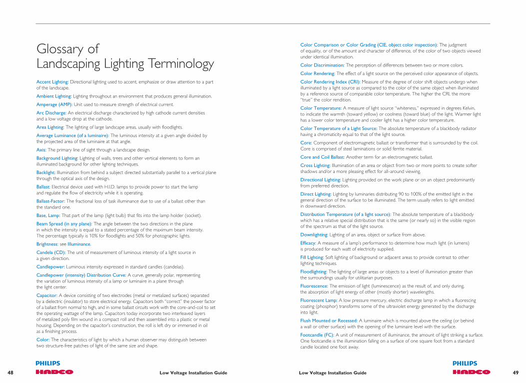
49Low Voltage Installation Guide48 Low Voltage Installation Guide
Color Comparison or Color Grading (CIE, object color inspection): The judgment of equality, or of the amount and character of difference, of the color of two objects viewed under identical illumination.
Color Discrimination: The perception of differences between two or more colors.
Color Rendering: The effect of a light source on the perceived color appearance of objects.
Color Rendering Index (CRI): Measure of the degree of color shift objects undergo when illuminated by a light source as compared to the color of the same object when illuminated by a reference source of comparable color temperature. The higher the CRI, the more “true” the color rendition.
Color Temperature: A measure of light source “whiteness,” expressed in degrees Kelvin, to indicate the warmth (toward yellow) or coolness (toward blue) of the light. Warmer light has a lower color temperature and cooler light has a higher color temperature.
Color Temperature of a Light Source: The absolute temperature of a blackbody radiator having a chromaticity equal to that of the light source.
Core: Component of electromagnetic ballast or transformer that is surrounded by the coil. Core is comprised of steel laminations or solid ferrite material.
Core and Coil Ballast: Another term for an electromagnetic ballast.
Cross Lighting: Illumination of an area or object from two or more points to create softer shadows and/or a more pleasing effect for all-around viewing.
Directional Lighting: Lighting provided on the work plane or on an object predominantly from preferred direction.
Direct Lighting: Lighting by luminaries distributing 90 to 100% of the emitted light in the general direction of the surface to be illuminated. The term usually refers to light emitted in downward direction.
Distribution Temperature (of a light source): The absolute temperature of a blackbody which has a relative special distribution that is the same (or nearly so) in the visible region of the spectrum as that of the light source.
Downlighting: Lighting of an area, object or surface from above.
Efficacy: A measure of a lamp’s performance to determine how much light (in lumens) is produced for each watt of electricity supplied.
Fill Lighting: Soft lighting of background or adjacent areas to provide contrast to other lighting techniques.
Floodlighting: The lighting of large areas or objects to a level of illumination greater than the surroundings usually for utilitarian purposes.
Fluorescence: The emission of light (luminescence) as the result of, and only during, the absorption of light energy of other (mostly shorter) wavelengths.
Fluorescent Lamp: A low pressure mercury, electric discharge lamp in which a fluorescing coating (phosphor) transforms some of the ultraviolet energy generated by the discharge into light.
Flush Mounted or Recessed: A luminaire which is mounted above the ceiling (or behind a wall or other surface) with the opening of the luminaire level with the surface.
Footcandle (FC): A unit of measurement of illuminance, the amount of light striking a surface. One footcandle is the illumination falling on a surface of one square foot from a standard candle located one foot away.
Glossary of Landscaping Lighting TerminologyAccent Lighting: Directional lighting used to accent, emphasize or draw attention to a part of the landscape.
Ambient Lighting: Lighting throughout an environment that produces general illumination.
Amperage (AMP): Unit used to measure strength of electrical current.
Arc Discharge: An electrical discharge characterized by high cathode current densities and a low voltage drop at the cathode.
Area Lighting: The lighting of large landscape areas, usually with floodlights.
Average Luminance (of a luminaire): The luminous intensity at a given angle divided by the projected area of the luminaire at that angle.
Axis: The primary line of sight through a landscape design.
Background Lighting: Lighting of walls, trees and other vertical elements to form an illuminated background for other lighting techniques.
Backlight: Illumination from behind a subject directed substantially parallel to a vertical plane through the optical axis of the design.
Ballast: Electrical device used with H.I.D. lamps to provide power to start the lamp and regulate the flow of electricity while it is operating.
Ballast-Factor: The fractional loss of task illuminance due to use of a ballast other than the standard one.
Base, Lamp: That part of the lamp (light bulb) that fits into the lamp holder (socket).
Beam Spread (in any plane): The angle between the two directions in the plane in which the intensity is equal to a stated percentage of the maximum beam intensity. The percentage typically is 10% for floodlights and 50% for photographic lights.
Brightness: see Illuminance.
Candela (CD): The unit of measurement of luminous intensity of a light source in a given direction.
Candlepower: Luminous intensity expressed in standard candles (candelas).
Candlepower (intensity) Distribution Curve: A curve, generally polar, representing the variation of luminous intensity of a lamp or luminaire in a plane through the light center.
Capacitor: A device consisting of two electrodes (metal or metalized surfaces) separated by a dielectric (insulator) to store electrical energy. Capacitors both “correct” the power factor of a ballast from normal to high, and in some ballast circuits work with the core-and-coil to set the operating wattage of the lamp. Capacitors today incorporate two interleaved layers of metalized poly film wound in a compact roll and then assembled into a plastic or metal housing. Depending on the capacitor’s construction, the roll is left dry or immersed in oil as a finishing process.
Color: The characteristics of light by which a human observer may distinguish between two structure-free patches of light of the same size and shape.

51Low Voltage Installation Guide50 Low Voltage Installation Guide
Lamp: A generic term for a man-made source of light. The lighting industry term for lightbulb. It refers to the complete assembly including the internal parts as well as the outer bulb or tube and base(s).
Lamp Current: The current delivered to the lamp by the ballast to generate light.
Lamp Watts: The power consumed by the lamp to generate light.
(LED) Light Emitting Diode: A semiconductor device that emits incoherent narrow-spectrum light when electrically biased in the forward direction. An LED is a diode that is chip-mounted in a reflector cup and held in place by a milled steel frames connected to a pair of electrical wires. When current flows across the junction of the two different materials, light is produced from within the solid crystal chip.
[Average Rated] Life: The median time it takes for a lamp to burn out. For example, a typical incandescent lamp is expected, on average, to burn for 1,000 hours. Based upon continuous testing of lamps in laboratories, the 1,000-hour rating is that point when 50% of the test samples have burned out and 50% are still burning. Unless otherwise noted, fluorescent (linear and compact) rated life assumes three (3) hours average operating time per start, H.I.D. rated life assumes ten (10) hours average operating time per start.
Lighting System: The complete system of fixtures, lamps, wiring switches and power source to supply light to an environment. Auxiliary equipment can include transformers, photocells and accessories.
Light Output: The amount of light emitted by a lamp, measured in lumens.
Light Center (of a lamp): The center of the smallest sphere that would completely contain the light-emitting element of the lamp.
Light Center Length (of a lamp): The distance from the light center to a specified reference point on the lamp.
Lighting Effectiveness Factor (LEFv): The equivalent sphere illumination to ordinary measured or calculated illumination.
Light Loss Factor (LLF): A factor used in calculating illuminance after a given period of time and under given conditions. It takes into account temperature and voltage variations, dirt accumulation on luminaire and room surfaces, lamp depreciation, maintenance procedures, and atmosphere conditions. Formerly called maintenance factor.
Low-voltage Lighting System: A lighting system that operates on 12-volt current instead of the standard 120 volts or higher.
Lumen: The unit of measurement for the amount of light emitted by a lamp. One lumen per square foot is one footcandle.
[Initial] Lumens: Initial light output of a new lamp. For H.I.D. lamps the initial lumen rating is based on the light output of the lamp after it has been seasoned (burned or “aged”) for 100 hours.
[Mean] Lumens: Lamp light output (lumens) measured at 40% of rated lamp life for fluorescent, compact fluorescent and metal halide lamps, and 50% of rated life for mercury and HPS lamps.
Luminaire: A complete lighting unit, consisting of a housing to position and protect the lamp, and parts to connect the lamp to the power supply.
Luminaire Efficiency: The ratio of luminous flux (lumens) emitted by a luminaire to that emitted by the lamp or lamps used therein.
Luminance: The degree of apparent lightness of a surface: its brilliancy. Luminance is measured in footlamberts or candelas.
Footlambert (fL): A unit of luminance equal to 1/π candela per square foot, to the uniform luminance of a perfectly diffusing surface emitting or reflecting light at the rate of one lumen per square foot, or to the average luminance of any surface emitting or reflecting light at that rate. NOTE: The average luminance of any reflecting surface in footlamberts is, therefore, the product of the illumination in footcandles and the luminous reflectance of the surface.
General Lighting: Lighting designed to provide a substantially uniform level of illumination throughout an area, exclusive of any provision for special local requirements.
General Purpose Floodlight (GPF): A weatherproof unit constructed in such a way that the housing forms the reflecting surface. The assembly is enclosed by a glass cover.
Frequency: Rate of alteration in an AC current. Expressed in cycles per second or Hertz (Hz).
Glare: Bright light that distracts the viewer and/or interferes with seeing all elements in an environment in a comfortable manner.
Grade-Mounted: A luminaire which is normally recessed in the soil or installed in the hardscape so the top surface is flush with the surrounding surfaces.
Grazing Light: Lighting from an angle that accentuates the texture or surface dimension of walls, paving stones or architectural detail.
Halogen Lamp: See Tungsten-Halogen Lamp.
High Intensity Discharge (H.I.D.) Lamp: A lamp that produces light when electricity excites specific gases within a pressurized bulb. H.I.D. lamps include mercury vapor, metal halide and high pressure sodium types, and each requires special fixtures and ballasts.
High Pressure Sodium Lamp: An H.I.D. lamp that illuminates by radiation from sodium vapor, producing a distinctly yellowish color rendering. Available in clear or coated types.
Illuminance: The amount of light striking a surface or object measured in footcandles.
Illuminance (lux or footcandle) Meter: An instrument for measuring illuminance on a plane. Instruments which accurately respond to more than one spectral distribution are color corrected; for example, the spectral response is balanced to V (λ) or V’ (λ). Instruments which accurately respond to more than one spatial distribution of incident flux are cosine corrected; for example, the response to a source of unit luminous intensity, illuminating the detector from a fixed distance.
Illumination: The act of illuminating or the state of being illuminated. Often confused with “illuminance.”
Incandescent Lamp: A lamp that produces light when electricity heats a metal filament to incandescence.
Indirect Lighting: Lighting by luminaries distributing 90 to 100% of the emitted light upward.
Input Voltage: The voltage from the incoming power line to the ballast or fixture.
Isocandela Line: A line plotted on any appropriate set of coordinates to show directions in space, about a source of light, in which the intensity is the same. A series of such curves, usually for equal increments of intensity, is called an isocandela diagram.
Isofootcandle (isolux) Line: A line plotted on any appropriate set of coordinates to show all the points on a surface where the illuminance is the same. A series of lines for various illuminance values is known as an isofootcandle (or isolux) diagram.
Isolux (isofootcandle) Line: A line plotted on any appropriate set of coordinates to show all the points on a surface where the illuminance is the same. A series of such lines for various illuminance values is called an isolux (isofootcandle) diagram.

52 Low Voltage Installation Guide
Notes:_________________________________________________________________________________
_________________________________________________________________________________
_________________________________________________________________________________
_________________________________________________________________________________
_________________________________________________________________________________
_________________________________________________________________________________
_________________________________________________________________________________
_________________________________________________________________________________
_________________________________________________________________________________
_________________________________________________________________________________
_________________________________________________________________________________
_________________________________________________________________________________
_________________________________________________________________________________
_________________________________________________________________________________
_________________________________________________________________________________
_________________________________________________________________________________
_________________________________________________________________________________
Mercury Vapor Lamp: An H.I.D. lamp that produces light by radiation from mercury vapor, when supplied with electricity. Available in clear or phosphor-coated types, mercury lamps have a distinct blue-green color rendering that complements most foliage.
Metal Halide Lamps: An H.I.D. lamp that produces light by radiation from certain metallic vapors. Known for producing accurate color rendition, metal halide lamps are available in clear or phosphor-coated types.
Mirror Lighting: Lighting that utilizes water (from a pond, pool, etc.) to serve as a reflecting surface for landscape and architectural elements.
PAR Lamp: Parabolic aluminized reflector lamp, a type of lamp suitable for exposed outdoor applications.
Quartz Lamp: See Tungsten-Halogen Lamp.
Quality of Lighting: Characteristics of the illumination of an environment that contribute favorably to visual performance, visual comfort, ease of seeing, safety and aesthetics.
R Lamp: Reflector lamp.
Reflectance: A measure of the amount of light that strikes a surface and is reflected. Higher reflectance occurs with lighter-colored objects or surfaces.
Reflection: A general term for the process by which the incident flux leaves a surface or medium from the incident side, without change in frequency. NOTE: Reflection is usually a combination of regular and diffuse reflection.
Reflector: A device used to redirect light from a lamp by the process of reflection.
Security Lighting: Lighting to protect people and property from criminal activity. When properly employed, security lighting eliminates shadows near buildings and provides even landscape illumination for pedestrian safety.
Shadowing: Lighting that projects shadows of foliage on a wall or other vertical surface.
Spacing: For roadway lighting, the distance between successive lighting units, measured along the center line of the street.
Tungsten-Halogen Lamp: A type of incandescent lamp containing a tungsten filament within a pressurized fused-quartz bulb filled with halogen gas. Also referred to as quartz or halogen lamp. Generally smaller, higher in output, with more neutral color rendering and longer lamp life than incandescent lamps of the same wattage.
Transformer: A device used to convert 120-volt current into 12-volt current for low-voltage lighting systems.
Uplighting: Lighting of an object or surface from below.
Voltage: A measurement of the electromotive force (electrical pressure) in an electrical circuit or device expressed in volts. Voltage can be thought of as being analogous to the pressure in a waterline.
Voltage to Luminaire Factor: The fractional loss of task illuminance due to improper voltage at the luminaire.
Watt: The unit of measurement of electrical power. Electrical power is the product of the voltage to a device: ballast, lamp, lighting fixture, etc., times the current through that device, times the power factor of that device.

Philips Hadco100 Craftway Drive • P.O. Box 128 • Littlestown, PA 17340
Phone: 866-423-2658 • Fax: 717-359-9289
www.hadco.com
© 2012 Philips Group
Printed in U.S.A.
PH-1020-1203-5K
Member