Embed Size (px)
Citation preview

ContentsDescription Page
1: Introduction . . . . . . . . . . . . . . . . . . . . . . . . . . . . 32: Receiving, handling, and storage . . . . . . . . . . . 43: Equipment description . . . . . . . . . . . . . . . . . . . 84: Installation . . . . . . . . . . . . . . . . . . . . . . . . . . . . 165: Inspection and testing prior to operation . . . . 276: Periodic Inspection and testing . . . . . . . . . . . . 287: Document references . . . . . . . . . . . . . . . . . . . 30
Effective March 2020Supersedes November 2019Instruction Booklet IB01901001E
Instructions for Magnum DST
metal-enclosed low-voltage assemblies

2
Instruction Booklet IB01901001EEffective March 2020
Instructions for Magnum DS
metal-enclosed low-voltage assemblies
EATON www.eaton.com
Read and understand these instructions before attempting to unpack, assemble, operate or maintain this type equipment . All pos-sible contingencies which may arise during installation, operation or maintenance, and all details and variations of this equipment do not purport to be covered by these instructions . If further information is desired by purchaser regarding his particular installation, operation or maintenance of particular equipment, contact the local Eaton repre-sentative .
m WARNINGMETAL-ENCLOSED LOW-VOLTAGE ASSEMBLIES COVERED BY THESE INSTRUCTIONS ARE DESIGNED AND TESTED TO OPERATE WITHIN THEIR NAMEPLATE RATINGS. OPERATION OUTSIDE OF THESE RATINGS MAY CAUSE THE EQUIPMENT TO FAIL RESULTING IN DEATH, SERIOUS INJURY AND/OR PROPERTY DAMAGE. ALL RESPONSIBLE PERSONNEL SHOULD LOCATE THE EQUIPMENT RATING NAMEPLATE AND BE FAMILIAR WITH THE INFORMATION PROVIDED THEREON. A TYPICAL MAGNUM DS® SWITCHGEAR NAMEPLATE IS SHOWN IN FIGURE 1.
Figure 1. Typical blank Magnum DS rating nameplate
m CAUTIONALL APPLICABLE SAFETY CODES, SAFETY STANDARDS, AND SAFETY REG-ULATIONS MUST BE STRICTLY ADHERED TO WHEN INSTALLING, OPERAT-ING, OR MAINTAINING THIS EQUIPMENT.
Purpose
This instruction manual is expressly intended to cover the installa-tion, operation and maintenance of Magnum DS metal-enclosed low-voltage assemblies used with Magnum DS, Magnum SB or Series NRX Power circuit breakers or CM52 network protectors .
For application information consult applicable descriptive bulletins, application publications and/or the applicable industry standards .
For installation, operation and maintenance of low-voltage power cir-cuit breakers see separate instruction books listed in Section 7 .
NOTICETHE DANGER, WARNING AND CAUTION MESSAGES INCLUDED AS PART OF THE PROCEDURAL STEPS IN THIS MANUAL ARE FOR PERSONNEL SAFETY AND PROTECTION OF EQUIPMENT FROM DAMAGE. AN EXAMPLE OF A TYPICAL WARNING LABEL HEADING IS SHOWN ABOVE THIS PARAGRAPH TO FAMILIARIZE PERSONNEL WITH THE TYPE OF PRESENTATION. THIS WILL HELP TO ASSURE THAT PERSONNEL ARE ALERT TO THESE MESSAGES. IN ADDITION, THESE MESSAGES ARE ALL UPPERCASE AND BOLDFACE.

3
Instruction Booklet IB01901001EEffective March 2020
Instructions for Magnum DS
metal-enclosed low-voltage assemblies
EATON www.eaton.com
Section 1: Introduction1.1 General information
Magnum DS switchgear low voltage assemblies with Magnum DS, Magnum SB or Series NRX AC power circuit breakers , or CM52 network protectors, control and protect power circuits up to and including 600 volts ac and interrupting capacities up to and including 200kA . The switchgear or switchboard assembly is composed of ver-tical sections that are arranged to suit the customer’s requirements . Magnum DS Low Voltage assemblies utilize a four-cell high structure design consisting of various combinations of Magnum DS, Magnum SB or Series NRX low-voltage AC power circuit breakers or CM52 network protectors and auxiliary compartments (Figure 2) . Bus and cable compartments provide space for connections, maintenance and inspection . These spaces are rear-accessible as a standard, or may be front-accessible as an option . See Section 3 for details .
This instruction manual contains important procedures and informa-tion pertinent to the receiving, handling, storage, installation, opera-tion and maintenance of Magnum DS metal-enclosed low-voltage assemblies . Information provided in this instruction manual and by other supplied documentation and/or drawings should be read and understood by all personnel responsible for supervision, operation or maintenance . Familiarization should always include the character-istics of each piece of equipment contained in or mounted on the assembly .
Proper installation, operation and maintenance are essential to assure continued satisfactory service from the equipment . It should not be installed in places where it will be required to operate at volt-age, currents or fault capacities greater than those for which it was designed, or where the environmental conditions are dirty, corrosive, humid or otherwise harsh or unsuitable .(Ref . ANSI C37 .20 .1 for abnormal operation conditions) .
Figure 2. Typical Magnum DS low-voltage indoor switchgear (front view)
The information given in this manual applies to NEMA1 (Indoor) Low Voltage assemblies utilizing Magnum DS, Magnum SB or Series NRX drawout power circuit breakers unless otherwise noted . For other options, see the addendum documents listed in Section 7 .
1.2 Safety features
Each Magnum DS assembly is manufactured with built in interlocks and safety-related features . They are provided to reduce hazards to operating personnel and provide proper operating sequences .
m DANGERMETAL-ENCLOSED LOW-VOLTAGE ASSEMBLIES ARE PROVIDED WITH MANY SAFETY FEATURES. NEVERTHELESS, WHEN CONNECTED THEY CONTAIN POWER CIRCUITS WITH HIGH FAULT CAPACITY. THE VOLTAGES AND POWER LEVELS AVAILABLE IN THIS EQUIPMENT MAKE CONTACT WITH BARE CONDUCTORS OR TERMINALS EXTREMELY DANGEROUS, AND IS LIKELY TO BE FATAL. ALL POWER SHOULD BE TURNED OFF OR APPROPRIATE PROTECTIVE EQUIPMENT USED WHEN WORKING ON SUCH EQUIPMENT. IN ADDITION TO THE HAZARDS INHERENT TO THE LOW-VOLTAGE ASSEMBLY ITSELF, OPERATION BY UNQUALIFIED PERSONS MAY CAUSE INDIRECT DAMAGE TO CONNECTED EQUIPMENT AND INJURY TO OPERATORS OF CONNECTED EQUIPMENT. UNDER NO CIRCUMSTANCE SHOULD THE INTERLOCKS OR OTHER SAFETY FEATURES BE MADE INOPERATIVE OR DISABLED, AS THIS MAY RESULT IN DEATH, BODILY INJURY OR PROPERTY DAMAGE. TO PROTECT PERSONNEL DURING THE INSTALLATION, OPERATION AND MAINTENANCE OF THIS EQUIPMENT, THE FOLLOWING PRACTICES MUST BE FOLLOWED:
1.3 Safety practices
Magnum DS low-voltage assemblies are complex, high current elec-trical equipment designed to operate within the voltage and current limitations shown on their respective nameplates (Figure 1) . Do not apply this equipment to systems with voltages and/or currents in excess of these limits .
1 . Only qualified electrical personnel familiar with the construction and operation of this equipment and the associated hazards should be permitted to work on such equipment . Additionally, only qualified personnel should be permitted to install or operate such equipment .
2 . Always be certain that the primary and secondary circuits are de-energized before attempting any maintenance .
3 . For maximum safety, only insert a completely assembled breaker into an energized cell . Front covers are safety features and must be in place when energized .
4 . While in the assembly, always ensure that drawout circuit break-ers are in one of three intended positions: “Connect”, “Test”, or “Disconnect” . A circuit breaker permitted to remain in an inter-mediate position could result in control circuits being improperly connected causing other equipment to malfunction .
5 . Do not remove access covers unless the circuits to be exposed are de-energized .
6 . Use calibrated test equipment of known reliability to confirm that all circuits are de-energized before servicing .
7 . After maintenance, be certain every current transformer second-ary circuit is completely connected or shorted .

4
Instruction Booklet IB01901001EEffective March 2020
Instructions for Magnum DS
metal-enclosed low-voltage assemblies
EATON www.eaton.com
m DANGERIF THE SECONDARY CIRCUIT OF ANY CURRENT TRANSFORMER IS LEFT OPEN WITHOUT LOAD, AND ITS PRIMARY CIRCUIT IS ENERGIZED, A DANGEROUSLY HIGH VOLTAGE IS DEVELOPED ACROSS TRANSFORMER SECONDARY TERMINALS. TO PREVENT DEATH, BODILY INJURY OR ELECTRICAL SHOCK, EITHER DE-ENERGIZE THE CIRCUIT BY OPENING THE BREAKER, OR SHORT CIRCUIT CURRENT TRANSFORMER SECONDARY TERMINALS, BEFORE ENERGIZING THE CIRCUIT AND PROCEEDING WITH MAINTENANCE.
8 . Always be certain that all assembly hardware is in place and bolted tightly before inserting a drawout circuit breaker into its compartment .
m WARNING
FAILURE TO FOLLOW THESE DIRECTIONS MAY RESULT IN DEATH, SERIOUS BODILY INJURY OR PROPERTY DAMAGE.
1.4 Qualified personnel
For the purpose of operating switchgear and switchboard assemblies, a person who has been thoroughly trained in the operation of power circuit breakers and any included instrumentation and who has complete knowledge of the loads connected to the assembly may be considered to be a qualified person .
For the purpose of installing, inspecting and maintaining switchgear and switchboard assemblies, a qualified person must ALSO be thoroughly trained in regard to the hazards inherent to working with electricity and in the proper way to perform such work . The individual should be able to de-energize,clear and lockout/tagout circuits in accordance with established safety practices . In addition, the individual should be equipped with, and trained in the use of, personal protective equipment (rubber gloves, arc-flash clothes, etc .) for those occasions when it is not possible to de-energize all circuits before doing maintenance work in the area .
1.5 Precautions
1 . If relays are included, remove all blocking . Check control circuits (except voltage and current transformer circuits) for grounds and short circuits before applying control power .
2 . Connect the assembly to the station ground before applying any power .
3 . In case of fire, do not use liquid fire extinguisher until all circuits have been disconnected .
4 . If an indoor assembly is to be stored prior to installation, it must be protected from the weather and kept free of condensation .
5 . If an outdoor assembly is to be stored prior to installation, provi-sions must be made for energizing the space heaters to prevent condensation of moisture inside the assembly .
1.6 Other publications and documentation
In addition to this instruction manual, other printed information and documentation is supplied with each assembly . This additional infor-mation will include, but not necessarily be limited to, a Magnum DS low-voltage power circuit breaker instruction manual, arrangement drawings, and connection diagrams . For additional references see Section 7 .
Section 2: Receiving, handling and storage2.1 General information
Magnum DS metal-enclosed low-voltage assemblies are shipped in one or more shipping groups, depending on the number of vertical sections, or the limitations of handling facilities at the installation site . This would usually be up to five vertical sections for an indoor assembly, or up to three or four sections for an outdoor assembly .
Indoor shipping groups are secured by lag bolts to wooden skids that extend beyond all sides of the switchgear . All shipping sections are shipped so as to be protected from the weather during shipment but are not suitable for storage outdoors as shipped . Outdoor assemblies are not weatherproof until completely assembled . Treat them the same as indoor equipment until fully assembled . See IB01900002E for more information .
2.2 Receiving
When a switchgear assembly reaches its destination, the purchaser should check the material received against the shipping list to be certain that all items have arrived . Note accurately any discrepancies . Each shipping group is plainly marked with or accompanied by an identifying shop order number, general order number and shipping weight . Each shipment includes a contents list which is a part of the overall package of shipping papers . To avoid the loss of any parts, the contents of each container should be carefully checked against the packing list . Do not discard any packing material until it is certain that every item has been received in the proper condition and that certain packing material will not be required later for equipment storage . Larger items, such as indoor traveling lifters, are shipped in separate cartons or boxes . Other loose and unmounted items may be packed in the same box as the lifter (Figure 3) . These items, such as shipping split hardware, should be logged in and set aside in a safe location until the assembly has been set in its final position .
Equipment shipped from the factory is carefully packed and inspected prior to its departure . On occasion, however, equipment damage is incurred during transportation . If any damage is found, file a damage claim immediately with the transportation carrier and notify an Eaton representative . All claims should be filed as soon as possible and include applicable part numbers, shop order numbers and/or general order numbers .
2.3 Precautions
It is preferable to use an overhead crane when moving the assembly . Circumstances at the installation location may prevent the use of an overhead crane for all movement . In such instances, the careful use of rollers can be employed . Although the methods for moving indoor and outdoor assemblies are similar, the techniques vary slightly . The differences are highlighted in this section .
Figure 3. Carton containing indoor lifter assembly

5
Instruction Booklet IB01901001EEffective March 2020
Instructions for Magnum DS
metal-enclosed low-voltage assemblies
EATON www.eaton.com
2.3.1 Overhead lifting
m WARNINGFAILURE TO FOLLOW LIFTING INSTRUCTIONS MAY RESULT IN DEATH OR SERIOUS BODILY INJURY. READ INSTRUCTIONS FOR LIFTING SWITCHGEAR PRIOR TO ATTACHING CABLES, CHAINS OR SPREADER BARS.
Indoor assemblies: For ease of handling by crane, each indoor ship-ping group is equipped with a lifting plate that extends the length of the shipping group . The lifting plate is designed and placed such that a spreader bar is not required between the lifting cables/chains (Figure 4) . The acute angle between the lifting cables/chains and the horizontal top of the gear, must never be less than 45° . Spreader bars can, however, be used if the overhead space is limited for crane use .
Outdoor Assembly: See IB01900002E .
Figure 4. Lifting sling
2.3.2 Rolling
If during the moving and positioning process it is not feasible to use an overhead crane, the equipment can be moved on construction rollers . If conditions are such that the indoor assemblies cannot be rolled into position with the shipping skids in place, they may be removed before rolling the assemblies . For best results, however, the shipping skids should be used . Use no less than four evenly spaced rollers for assembly movement . Since equipment length can vary, each 1 .5 to 2 .0 feet (457 to 610 mm) of equipment length requires a roller . As the equipment is carefully moved, the roll-ers that become free at the end opposite the movement direction should once again be placed at the front for continued movement .
45°
2.3.3 Shipping skid removal
The wooden shipping skid bolted to the bottom of an indoor assem-bly should be removed once the indoor assembly is in its permanent location . Lag bolts attach the shipping skids to the assembly from the inside: typically six bolts per vertical section of rear-accessible assemblies; four bolts per vertical section of front-accessible assem-blies . The holes that remain in the equipment after the skids and lag bolts are removed are used in securing the indoor assembly perma-nently in position . See Section 4 and base plan drawing 4A37896 for intended lag locations for various assembly configurations .
2.4 Temporary storage
An indoor switchgear or switchboard assembly which cannot be installed and put into service immediately should be stored in a dry and clean place, preferably indoors in a heated building . Conditions such as dampness, changes in temperature, dirty or corrosive atmospheres should be carefully avoided . Special precautions are required if the indoor assembly is to be stored outdoors . The assem-bly must be kept clean, well ventilated, and warm enough to prevent condensation . It will be necessary to cover the assembly and install temporary heating equipment . Approximately 250 watts per verti-cal section are required for average conditions . Outdoor storage of indoor equipment, even for a brief period, is not recommended and should be avoided . The covering provided during shipment for indoor assemblies is NOT adequate for outdoor storage . Covering must be adequate to protect the assembly from dust and falling debris, but loose enough to permit adequate ventilation . Place blocking on the roof of the equipment to keep covering material from restricting the air flow .
m CAUTIONCARE MUST BE TAKEN THAT INTEGRAL CONTROL POWER TRANSFORM-ERS ARE NOT BACK-FED. DISCONNECT PRIMARY AND SECONDARY FUSES.
During storage, all assemblies, whether indoor or outdoor, should be placed on a firm, level surface . This will prevent any unnecessary strain or possible distortion .
Store all other separately packaged accessory equipment in a clean, dry location . It is recommended that a waterproof cover be placed over circuit breaker cartons and the cartons kept in an indoor storage location when the circuit breakers are stored separately from the assembly .
45°

6
Instruction Booklet IB01901001EEffective March 2020
Instructions for Magnum DS
metal-enclosed low-voltage assemblies
EATON www.eaton.com
Figure 5. Four high vertical section (side view) rear-accessible
99.00[2514.60]
25.63[651.00]
20.28[515.11]
54.00 [1376.60] TO 90.00 [2286.00](IN 6.00 [152.40] INCREMENTS)
92.00[2336.80]
4.10[104.02]
VER
TIC
ALBU
SR
ISER
AREA
HORI
ZONT
ALCR
OSS
BUS
AREA
HORI
ZONT
ALCR
OSS
BUS
AREA
GROUND BUS
NEUTRALTAPS
METAL ENCLOSED "SHIPPING SPLIT" TERMINAL BLOCKS
OPTIONAL "TOP-OF-GEAR" BREAKER LIFTER
LIFTING PLATE
2A97855

7
Instruction Booklet IB01901001EEffective March 2020
Instructions for Magnum DS
metal-enclosed low-voltage assemblies
EATON www.eaton.com
Figure 6. Four high vertical section (side view) front-accessible
20.28[515.11]
40.16[1020.01]
92.00[2336.80]
4.10[104.14]
NEUTRAL TAPS
LIFTING PLATE
2A97855

8
Instruction Booklet IB01901001EEffective March 2020
Instructions for Magnum DS
metal-enclosed low-voltage assemblies
EATON www.eaton.com
Section 3: Equipment description3.1 General description
The following descriptions apply to standard metal-enclosed con-struction and wiring . Special features and control schemes are often incorporated per customer specifications . These special features are evident and portrayed on the drawings and diagrams for the specific assembly received . Instructions on apparatus such as relays, instru-ments, control switches and circuit breakers are included elsewhere in separate instruction books or sheets .
Each low-voltage (600 volts and below) indoor and outdoor metal-enclosed assembly is factory assembled and tested . It is designed to require a minimum amount of labor for installation .
Each metal-enclosed assembly consists of a stationary structure that includes one or more free-standing vertical sections mechanically and electrically joined to make a single coordinated installation . In rear-accessible units, a vertical section consists of three major divi-sions: the front breaker compartment, bus compartment, and cable compartment (Figure 5) . In front-accessible units, the three divisions are redistributed between a pair of vertical sections: front breaker compartment/bus compartment in one half; cable compartment/bus compartment in the remaining half (Figure 6) .
Type Magnum DS metal-enclosed assemblies are available for both indoor (NEMA type 1) and outdoor (NEMA type 3R) applications . The circuit breakers and design features are similar whether the instal-lation be indoor or outdoor . An outdoor metal-enclosed switchgear assembly is constructed by erecting an outdoor enclosure “shell” around a standard indoor switchgear assembly . See addendum IB01900002E for specific information regarding outdoor assemblies .
Modifications can be made to the NEMA 1 enclosure for use in drip resistant or sprinkler resistant environments . When this is the case, some parts are shipped separately to reduce the risk of damage dur-ing shipping and handling . Installation instructions are given in draw-ings included in the information packet attached to the side of the switchgear assembly (drawing 2A97884) . Should additional copies of this drawing be needed, contact your nearest Eaton sales office . Refer to Section 4 .3 .1 .1 for further information .
3.2 Front compartment
The front compartment is a bolted steel structure . This structure may be solely an auxiliary unit used to house instruments, relays, switch-es and their associated auxiliary equipment or it may be divided into a maximum of four individual cells (up to eight cells for Series NRX) used to house circuit breakers (Figures 7 and 8) . These individual cells may also be used as instrument cells by omitting the circuit breaker and its associated stationary parts . The hinged door then becomes available for mounting instruments, relays, etc .
The upper front portion of each breaker cell is reserved for terminal blocks and control wiring connected to the secondary terminals of the circuit breaker (Figure 10) . In UL1558 rated switchgear, this compartment is accessible by a door separate from the breaker . Breaker control devices and instrumentation may be mounted on the door covering this compartment . In UL891 rated switchboards, this compartment is accessible behind a larger breaker door that covers both compartments .
Figure 7. Magnum DS breaker in connected position
Figure 8. Series NRX breakers in connected position

9
Instruction Booklet IB01901001EEffective March 2020
Instructions for Magnum DS
metal-enclosed low-voltage assemblies
EATON www.eaton.com
Figure 9. Magnum DS breaker on extension rails
3.2.1 Breaker cells (draw-out)
m CAUTIONFAILURE TO HAVE ANY DRAW-OUT BREAKER COMPLETELY IN THE DIS-CONNECT POSITION BEFORE RACKING-IN CAN CAUSE SERIOUS EQUIP-MENT DAMAGE. ENSURE THAT THE BREAKER REACHES A POSITIVE STOP WHEN INSERTING INTO THE CELL PRIOR TO RACKING.
In draw-out cells equipped for circuit breakers, a permanently mount-ed cassette with extension rails supports the breaker (Figure 9) . The cassette provides the mounting for the stationary secondary control disconnecting contacts and is located in the top/front region of the breaker cell (Figure 10) . These provide the control circuit interface to the circuit breaker . In addition, the cassette provides the stationary ground contact for the circuit breaker, the truck operated switch (cell switch), and shorting terminal blocks for cell mounted instrument current transformers .
Figure 10. Magnum DS cell secondary terminals & cell mounted current transformer
A molded glass polyester plate at the rear of the breaker cell pro-vides mounting for the instrument class current transformers . (Cell mounted CT not available for Series NRX breakers .)
The breaker cell provides three positions for the circuit breaker iden-tified as “connect”, “test” and “disconnect” . Each specific position is indicated by the position indicator on the circuit breaker as it moves into and out of the cell, as well as a label affixed to the side of the cassette (Figure 11) . The “withdrawn” position is attained when the circuit breaker is removed from the cell with the extension rails fully extended .
Figure 11. Magnum DS breaker position label
In the “connect” position, both the primary and secondary contacts are engaged and the circuit breaker is ready for operation . In the “test” position, only the secondary control contacts are engaged and the circuit breaker can be monitored or operated electrically without energizing the power circuit . In the “disconnect” position, both the primary and secondary control contacts are disengaged and the entire circuit breaker is isolated . Unlike the “connect” and“test” positions, the circuit breaker is not held captive in the cell in the “disconnect” position . When the levering mechanism, located on the circuit breaker, indicates the “disconnect” position, the circuit breaker can be freely removed from the cell .
The breaker can be moved between the “connect”, “test” and “dis-connect” positions with the breaker door closed .
3.2.1.1 Breaker cassette (draw-out)
The breaker cassette supports the breaker in the cell and on the movable extension rails as the breaker is placed into or removed from the cell .
3.2.1.1.1 Extension rails (draw-out)
In the Magnum DS & Magnum SB family of breakers, as well as CM52 network protectors, the extension rails are withdrawn from the breaker cassette by pulling the black handles located on the end of the extension rails . Once extended, the breaker is placed onto the draw-out rails by aligning the hook features located on each side of the circuit breaker housing with the slotted features in the draw-out rails . The breaker is then pushed into the cell until it reaches a posi-tive stop .
In the Series NRX family of breakers, the extension rails are with-drawn from the breaker cassette by pulling up and forward on the round latch pin of each extension rail . Once lowered into the hori-zontal position, the Series NRX breaker can be placed onto the rails by aligning the wheels located on each side of the breaker with the top surface of the rails . The breaker is then pushed into the cell until it reaches a positive stop .

10
Instruction Booklet IB01901001EEffective March 2020
Instructions for Magnum DS
metal-enclosed low-voltage assemblies
EATON www.eaton.com
3.2.1.1.2 Breaker Interference Interlocks (Draw-Out)
Many Eaton draw-out circuit breakers of various frame sizes and interruption ratings share common physical dimensions . For exam-ple, an 800amp 50kaic and a 3200amp 100kaic have the same exter-nal dimensions . To prevent inadvertent insertion of circuit breakers with mismatching features, insufficient interrupting ratings, or incor-rect frame size into cells, interference interlocks are provided .
m DANGERDO NOT DISABLE AN INTERFERENCE INTERLOCK. IF A FAULT OCCURS, USE OF A CIRCUIT BREAKER NOT RATED FOR A PARTICULAR CELL APPLICATION COULD RESULT IN DEATH, BODILY INJURY AND SEVERE EQUIPMENT DAMAGE.
These interference interlocks are steel pins located on the floor of the breaker cassette . As the breaker is pushed into the cell, the mat-ing pins on the breaker bottom moves past a set of corresponding pins on the breaker cassette . If the breaker is not matched correctly for the cell, the pins will oppose each other and the breaker will be blocked from insertion into the cell .
3.2.1.2 Key interlocks
Optional key interlocks may be supplied when it is necessary to ensure the proper sequence of operation between two or more cir-cuit breakers or between a circuit breaker, fuse truck or transformer high voltage disconnect switch . The interlock mechanism functions by preventing closing of a breaker in a given cell . With Magnum breakers, the key interlock mechanism is typically located on the wire way side of the draw-out cassette (Figure 12) . The breaker can be removed, inserted, or a replacement breaker installed and the cell will remain trip-free so long as the interlock is engaged . The key interlock operates by pulling the slide forward, rotating the key, and removing it from the lock . The slide mechanism actuates a lever located on the circuit breaker, which prevents the breaker from being closed . The key can then be used in another location . The cell will remain trip-free until the key is put back into the lock, rotated, and the slide retracted . NRX series breakers currently do not have cell-mounted interlocks but can be provided with independent locks on the individual breakers .
Figure 12. Magnum DS cell key interlock
m CAUTIONTO FACILITATE MANUFACTURE AND INSTALLATION PROCEDURES, A KEY IS SUPPLIED WITH EACH LOCK. BEFORE PLACING A SWITCHGEAR ASSEM-BLY WITH KEY INTERLOCKS IN OPERATION, THE KEY SCHEME MUST BE CAREFULLY CHECKED, AND ONLY THE PROPER KEYS LEFT IN THE LOCKS. ALL EXTRA KEYS MUST BE REMOVED AND DESTROYED OR STORED WHERE NOT AVAILABLE TO OPERATING PERSONNEL. THIS PROCEDURE IS NECESSARY SINCE THE IMPROPER USE OF SPARE KEYS WILL DEFEAT THE INTERLOCKING SCHEME.
3.2.1.3 Metering current transformers
When required for metering, current transformers are normally posi-tioned inside the draw-out cassette around the stationary main con-tacts (Figure 10) . Features are provided in the main contact support for mounting front accessible current transformers . Optionally, cur-rent transformers may be located in the cable compartment around the load conductors . See Table 3-2 for metering accuracies .
Short circuiting terminal blocks are provided as standard for each set of current transformers .
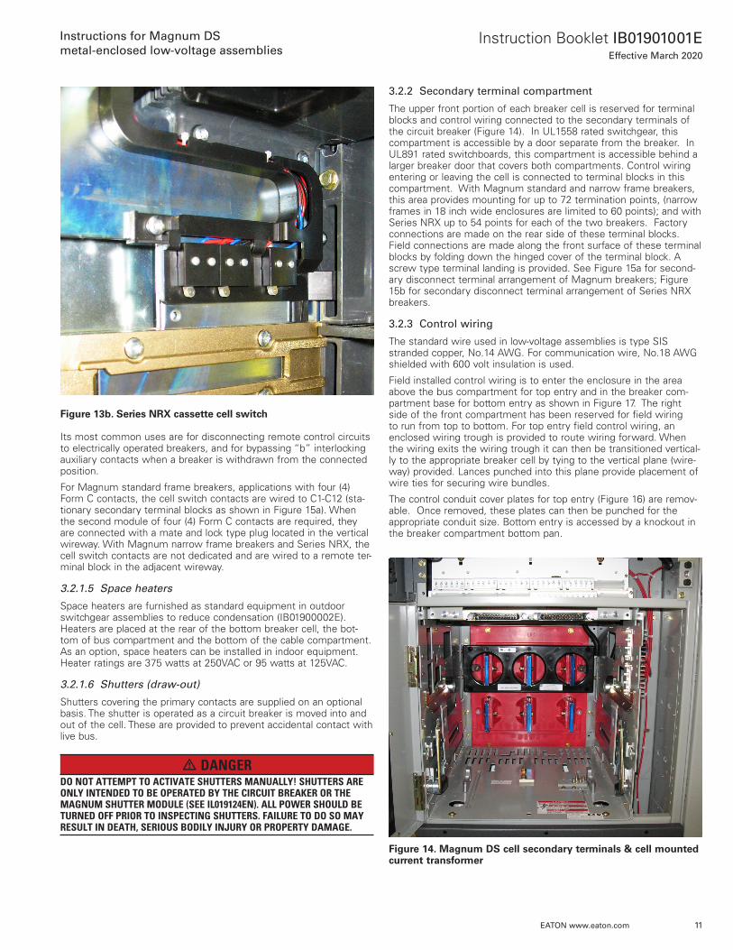
3.2.1.4 Cell switch (draw-out)
The cassette cell-switch is a compartment position switch for draw-out circuit breakers . It is operated by movement of the circuit breaker between the “connect”, “test” and “disconnect” positions . With Magnum breakers, the switch is located on the right-hand rear of the cassette . A plunger connected to the switch is actuated by the frame of the breaker as it moves into or out of the cell between the three positions (Figure 13a) .
With NRX series breakers, the switch is located on the left-hand front of the cassette (Figure 13b) . The switch is activated by an optional actuator mounted to the breaker . As a result, either cell switch can be used to electrically indicate the breaker position within the cell .
Figure 13a. Magnum DS cassette cell switch
11
Instruction Booklet IB01901001EEffective March 2020
Instructions for Magnum DS
metal-enclosed low-voltage assemblies
EATON www.eaton.com
Figure 13b. Series NRX cassette cell switch
Its most common uses are for disconnecting remote control circuits to electrically operated breakers, and for bypassing “b” interlocking auxiliary contacts when a breaker is withdrawn from the connected position .
For Magnum standard frame breakers, applications with four (4) Form C contacts, the cell switch contacts are wired to C1-C12 (sta-tionary secondary terminal blocks as shown in Figure 15a) . When the second module of four (4) Form C contacts are required, they are connected with a mate and lock type plug located in the vertical wireway . With Magnum narrow frame breakers and Series NRX, the cell switch contacts are not dedicated and are wired to a remote ter-minal block in the adjacent wireway .
3.2.1.5 Space heaters
Space heaters are furnished as standard equipment in outdoor switchgear assemblies to reduce condensation (IB01900002E) . Heaters are placed at the rear of the bottom breaker cell, the bot-tom of bus compartment and the bottom of the cable compartment . As an option, space heaters can be installed in indoor equipment . Heater ratings are 375 watts at 250VAC or 95 watts at 125VAC .
3.2.1.6 Shutters (draw-out)
Shutters covering the primary contacts are supplied on an optional basis . The shutter is operated as a circuit breaker is moved into and out of the cell . These are provided to prevent accidental contact with live bus .
m DANGERDO NOT ATTEMPT TO ACTIVATE SHUTTERS MANUALLY! SHUTTERS ARE ONLY INTENDED TO BE OPERATED BY THE CIRCUIT BREAKER OR THE MAGNUM SHUTTER MODULE (SEE IL019124EN). ALL POWER SHOULD BE TURNED OFF PRIOR TO INSPECTING SHUTTERS. FAILURE TO DO SO MAY RESULT IN DEATH, SERIOUS BODILY INJURY OR PROPERTY DAMAGE.
3.2.2 Secondary terminal compartment
The upper front portion of each breaker cell is reserved for terminal blocks and control wiring connected to the secondary terminals of the circuit breaker (Figure 14) . In UL1558 rated switchgear, this compartment is accessible by a door separate from the breaker . In UL891 rated switchboards, this compartment is accessible behind a larger breaker door that covers both compartments . Control wiring entering or leaving the cell is connected to terminal blocks in this compartment . With Magnum standard and narrow frame breakers, this area provides mounting for up to 72 termination points, (narrow frames in 18 inch wide enclosures are limited to 60 points); and with Series NRX up to 54 points for each of the two breakers . Factory connections are made on the rear side of these terminal blocks . Field connections are made along the front surface of these terminal blocks by folding down the hinged cover of the terminal block . A screw type terminal landing is provided . See Figure 15a for second-ary disconnect terminal arrangement of Magnum breakers; Figure 15b for secondary disconnect terminal arrangement of Series NRX breakers .
3.2.3 Control wiring
The standard wire used in low-voltage assemblies is type SIS stranded copper, No .14 AWG . For communication wire, No .18 AWG shielded with 600 volt insulation is used .
Field installed control wiring is to enter the enclosure in the area above the bus compartment for top entry and in the breaker com-partment base for bottom entry as shown in Figure 17 . The right side of the front compartment has been reserved for field wiring to run from top to bottom . For top entry field control wiring, an enclosed wiring trough is provided to route wiring forward . When the wiring exits the wiring trough it can then be transitioned vertical-ly to the appropriate breaker cell by tying to the vertical plane (wire-way) provided . Lances punched into this plane provide placement of wire ties for securing wire bundles .
The control conduit cover plates for top entry (Figure 16) are remov-able . Once removed, these plates can then be punched for the appropriate conduit size . Bottom entry is accessed by a knockout in the breaker compartment bottom pan .
Figure 14. Magnum DS cell secondary terminals & cell mounted current transformer
12
Instruction Booklet IB01901001EEffective March 2020
Instructions for Magnum DS
metal-enclosed low-voltage assemblies
EATON www.eaton.com
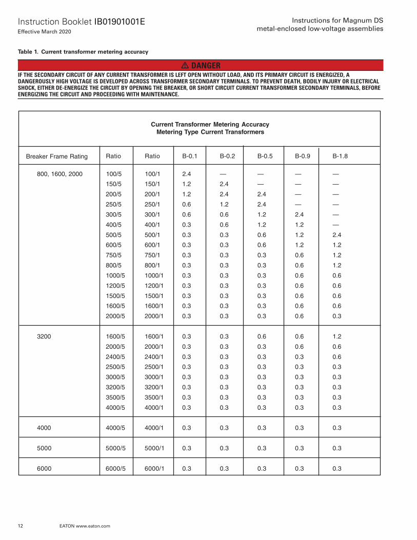
Table 1. Current transformer metering accuracy
m DANGERIF THE SECONDARY CIRCUIT OF ANY CURRENT TRANSFORMER IS LEFT OPEN WITHOUT LOAD, AND ITS PRIMARY CIRCUIT IS ENERGIZED, A DANGEROUSLY HIGH VOLTAGE IS DEVELOPED ACROSS TRANSFORMER SECONDARY TERMINALS. TO PREVENT DEATH, BODILY INJURY OR ELECTRICAL SHOCK, EITHER DE-ENERGIZE THE CIRCUIT BY OPENING THE BREAKER, OR SHORT CIRCUIT CURRENT TRANSFORMER SECONDARY TERMINALS, BEFORE ENERGIZING THE CIRCUIT AND PROCEEDING WITH MAINTENANCE.
Current Transformer Metering AccuracyMetering Type Current Transformers
Ratio Ratio B-0.1 B-0.2 B-0.5 B-0.9 B-1.8
800, 1600, 2000 100/5 100/1 2.4 — — — —
150/5 150/1 1.2 2.4 — — —
200/5 200/1 1.2 2.4 2.4 — —
250/5 250/1 0.6 1.2 2.4 — —
300/5 300/1 0.6 0.6 1.2 2.4 —
400/5 400/1 0.3 0.6 1.2 1.2 —
500/5 500/1 0.3 0.3 0.6 1.2 2.4
600/5 600/1 0.3 0.3 0.6 1.2 1.2
750/5 750/1 0.3 0.3 0.3 0.6 1.2
800/5 800/1 0.3 0.3 0.3 0.6 1.2
1000/5 1000/1 0.3 0.3 0.3 0.6 0.6
1200/5 1200/1 0.3 0.3 0.3 0.6 0.6
1500/5 1500/1 0.3 0.3 0.3 0.6 0.6
1600/5 1600/1 0.3 0.3 0.3 0.6 0.6
2000/5 2000/1 0.3 0.3 0.3 0.6 0.3
3200 1600/5 1600/1 0.3 0.3 0.6 0.6 1.2
2000/5 2000/1 0.3 0.3 0.3 0.6 0.6
2400/5 2400/1 0.3 0.3 0.3 0.3 0.6
2500/5 2500/1 0.3 0.3 0.3 0.3 0.3
3000/5 3000/1 0.3 0.3 0.3 0.3 0.3
3200/5 3200/1 0.3 0.3 0.3 0.3 0.3
3500/5 3500/1 0.3 0.3 0.3 0.3 0.3
4000/5 4000/1 0.3 0.3 0.3 0.3 0.3
4000 4000/5 4000/1 0.3 0.3 0.3 0.3 0.3
5000 5000/5 5000/1 0.3 0.3 0.3 0.3 0.3
6000 6000/5 6000/1 0.3 0.3 0.3 0.3 0.3
Breaker Frame Rating

13
Instruction Booklet IB01901001EEffective March 2020
Instructions for Magnum DS
metal-enclosed low-voltage assemblies
EATON www.eaton.com
Figure 15a. Magnum DS secondary disconnect terminal arrangement
Effective January 2003
W1
ST1
SHUNTTRIP
W2
ST2
W11
ALMc
W10
OT2M
W3
UV1
W4
UV2
W5
OT1c
W6
OT1M
W7
OT1B
W8
OT2B
W9
OT2c
W12
ALM1
W13
ALM2
W15
N1
W14 W16
N2
W17
G1
W18
G2
UNDER-VOLTAGE
OVER-CURRENT 1
TRIP UNITALARM
OVER-CURRENT 2
NEUTRALSENSOR
GROUNDFAULT
SENSOR
W25
CMM3
W24
CMM2
W23
CMM1
TRIPUNIT
POWER
MAINTENANCEMODE
W35
SR1
W34
ARM1
W36
SR2
W31W27
ZOUT
W26
CMM4
W29
ZIN
W28
ZCOM
ZONE INTER-LOCKING
W22
AGND
W21
+24V
W20
SGF1
W19
SGF2
GROUNDFAULT
JUMPER
W32W30 W33
ARM2
COMMUNICATIONS
OUT COM IN
SPRINGRELEASE
W52
AX4b
W54
AX4a
W53
AX4c
SPRINGCHARGE
W40
LCB
W39
SC
W38
EO2
W37
EO1
MOTOR AUX SWITCH 1
W45
AX1b
W46
AX2b
W44
AX1a
W47
AX2c
W51
AX3b
W50
AX3a
W49
AX3c
W48
AX2a
W42
LCM
W41
LCc
LATCHCHECKSWITCH
W43
AX1c
AUX SWITCH 2 AUX SWITCH 3 AUX SWITCH 4
NRX CUSTOMER INTERFACE SECONDARY TERMINALSSTANDARD ARRANGEMENT
9257C95
These contact points not available on Magnum narrow frames
in 18” wide enclosures
Figure 15b. Series NRX secondary disconnect terminal arrangement

14
Instruction Booklet IB01901001EEffective March 2020
Instructions for Magnum DS
metal-enclosed low-voltage assemblies
EATON www.eaton.com
Figure 16. Top conduit cover plate
3.2.4 Auxiliary/instrumentation compartment
Auxiliary/instrumentation compartments are normally the same physical size as a circuit breaker cell . They are used to house and mount instruments, control components and other auxiliary devices . The compartment has a hinged front door that is used for mounting a variety of devices (Figure 18) .
Figure 17. Field installed control wiring
'D' CELL
'C' CELL
'B' CELL
'A' CELL
9253C21
BOTTOM ENTRY CONDUIT KNOCKOUT
WHEN BREAKER IS OFFSET TO RIGHT SIDE OFSTRUCTURE, ENTRY IS ON LEFT SIDE OF STRUCTUREIN DOUBLE-WIDE ENCLOSURES ENTRY CAN BE EITHERLEFT, RIGHT OR BOTH.
TOP ENTRY CONDUIT COVER PLATE WIRING TROUGH
BREAKER SECONDARY TERMINAL CONNECTIONS
CURENT TRANSFORMER SHORT CIRCUITTERMINAL BLOCK
VERTICAL WIRING PLANE FOR TYING WIRING
CONTROL AND INSTRUMENTATION WIRE FIELD INSTALLATION PROCEDURE
WIREWAY PATH ILLUSTRATED BY STANDARD FRAME MAGNUM BREAKERS SHOWN; HOWEVER ALLMAGNUM DS SWITCHGEAR AND SWITCHBOARDS HAVE CONTROL CONDUIT IN SAME LOCATION.
NOTES:
1. REMOVE CONDUIT COVER PLATE AT TOP OR KNOCKOUT AT BOTTOM OF STRUCTURE AND DRILL APPROPRIATE SIZE CLEARANCE HOLES FOR CONDUIT.
2. AFTER TOP CONDUIT INSTALLATION, ROUTE WIRING TO FRONT OF SWITCHGEAR THROUGH THE ENCLOSED METAL TROUGH PROVIDED. A VERTICAL PLANE WIREWAY WITH WIRE TIE LANCES IS PROVIDED FOR ROUTING WIRE VERTICALLY TO THE APPROPRIATE BREAKER CELL LOCATION. BOTTOM ENTRY SIMILAR.
3. AFTER ROUTING THE WIRE TO THE APPROPRIATE CELL ELEVATION, GUIDE THE WIRE HORIZONTALLY TO THE CORRESPONDING SECONDARY TERMINAL COMPARTMENT BEING CAREFUL TO TIE WIRES ABOVE THE TERMINAL BLOCKS PROVIDED. MAKE APPROPRIATE CONNECTIONS.
Figure 18. Auxiliary compartment door
3.2.5 Auxiliary/transition section
Full height auxiliary sections with hinged front doors or transition sections with bolted covers are provided for a variety of reasons; (1) additional bus space needed for matching up to different equipment assemblies; (2) coupling to a non-standard transformer; (3) mounting and wiring of additional control equipment . These vertical sections are typically either 12 inches (305 mm) or 22 inches (559 mm) wide .
15
Instruction Booklet IB01901001EEffective March 2020
Instructions for Magnum DS
metal-enclosed low-voltage assemblies
EATON www.eaton.com
3.3 Bus compartment
The bus compartment provides space for vertical and horizontal bus . The compartment is located just behind the front compartment and is fully isolated from breaker and auxiliary cells . (See Figure 5) In rear accessible enclosures, optional grounded steel or aluminum barriers may be placed between the bus and rear cable connections, pro-viding an additional degree of safety . This helps prevent accidental contact with the main bus during maintenance procedures . In front accessible enclosures, similar optional barriers may isolate the bus compartment from the front cable connections .
The horizontal main bus ties the vertical sections together electri-cally; the vertical bus feeds the individual breaker compartments . Bus sizing is based on ANSI standard temperature rise criteria of 65 degrees C over 40 degrees C ambient . All bus meets industry standard phase-to-phase clearance without utilizing insulated bus . Standard main and section bus is silver-plated copper with tin-plated copper optional .
3.4 Cable compartments
3.4.1 Cable compartment (rear accessible)
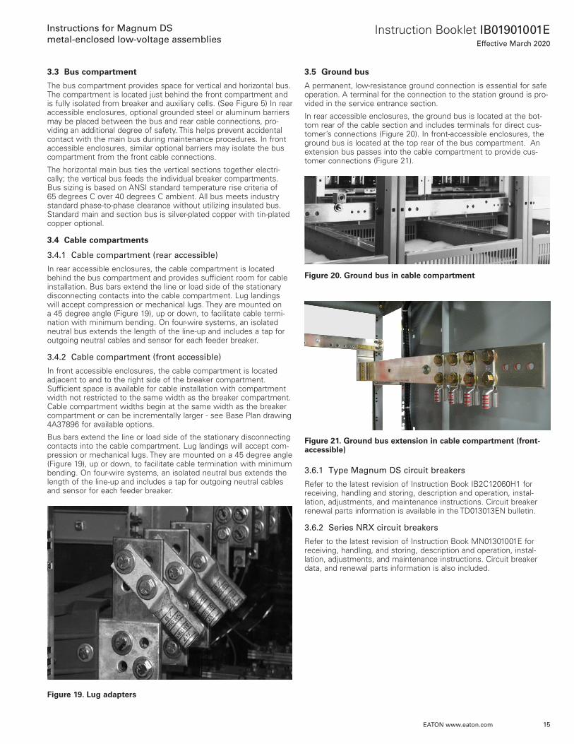
In rear accessible enclosures, the cable compartment is located behind the bus compartment and provides sufficient room for cable installation . Bus bars extend the line or load side of the stationary disconnecting contacts into the cable compartment . Lug landings will accept compression or mechanical lugs . They are mounted on a 45 degree angle (Figure 19), up or down, to facilitate cable termi-nation with minimum bending . On four-wire systems, an isolated neutral bus extends the length of the line-up and includes a tap for outgoing neutral cables and sensor for each feeder breaker .
3.4.2 Cable compartment (front accessible)
In front accessible enclosures, the cable compartment is located adjacent to and to the right side of the breaker compartment . Sufficient space is available for cable installation with compartment width not restricted to the same width as the breaker compartment . Cable compartment widths begin at the same width as the breaker compartment or can be incrementally larger - see Base Plan drawing 4A37896 for available options .
Bus bars extend the line or load side of the stationary disconnecting contacts into the cable compartment . Lug landings will accept com-pression or mechanical lugs . They are mounted on a 45 degree angle (Figure 19), up or down, to facilitate cable termination with minimum bending . On four-wire systems, an isolated neutral bus extends the length of the line-up and includes a tap for outgoing neutral cables and sensor for each feeder breaker .
Figure 19. Lug adapters
3.5 Ground bus
A permanent, low-resistance ground connection is essential for safe operation . A terminal for the connection to the station ground is pro-vided in the service entrance section .
In rear accessible enclosures, the ground bus is located at the bot-tom rear of the cable section and includes terminals for direct cus-tomer’s connections (Figure 20) . In front-accessible enclosures, the ground bus is located at the top rear of the bus compartment . An extension bus passes into the cable compartment to provide cus-tomer connections (Figure 21) .
Figure 20. Ground bus in cable compartment
Figure 21. Ground bus extension in cable compartment (front-accessible)
3.6.1 Type Magnum DS circuit breakers
Refer to the latest revision of Instruction Book IB2C12060H1 for receiving, handling and storing, description and operation, instal-lation, adjustments, and maintenance instructions . Circuit breaker renewal parts information is available in the TD013013EN bulletin .
3.6.2 Series NRX circuit breakers
Refer to the latest revision of Instruction Book MN01301001E for receiving, handling, and storing, description and operation, instal-lation, adjustments, and maintenance instructions . Circuit breaker data, and renewal parts information is also included .

16
Instruction Booklet IB01901001EEffective March 2020
Instructions for Magnum DS
metal-enclosed low-voltage assemblies
EATON www.eaton.com
Section 4: Installation
m WARNINGBEFORE PROCEEDING WITH ANY INSTALLATION, TESTING, START-UP OR MAINTENANCE, REVIEW ALL OF SECTION 1 FOR SAFETY PRACTICES AND RECOMMENDATIONS. FAILURE TO DO SO MAY RESULT IN DEATH, SERI-OUS BODILY INJURY OR PROPERTY DAMAGE.
4.1 General information
This section contains instructions for installing Magnum DS metal-enclosed low-voltage assemblies . Proper installation of Magnum DS metal-enclosed low-voltage switchgear assemblies is of prime importance . Too much emphasis cannot be placed on this phase of the work . Study the associated instruction manuals and drawings carefully .
m CAUTIONPERSONNEL INSTALLING THIS EQUIPMENT MUST BE THOROUGHLY FAMILIAR WITH ALL ASSOCIATED INSTRUCTION MANUALS AND APPLI-CABLE GOVERNING CODES. ADDITIONALLY, ALL DRAWINGS WHETHER MECHANICAL OR ELECTRICAL MUST BE UNDERSTOOD AND STRICTLY FOLLOWED TO PREVENT POSSIBLE DAMAGE TO THE SWITCHGEAR OR EQUIPMENT BEING PROTECTED.
4.2 Location and foundation
Magnum DS metal-enclosed low-voltage assemblies are constructed at the factory on smooth level surfaces to assure correct alignment of all parts . Extra care by the purchaser in selecting the location and preparing the foundation will result in reduced installation costs, as well as good equipment performance .
4.2.1 Location
In general, the location will have been determined during the speci-fication and/or procurement phases . Indoor locations impose certain requirements which must be met so that the switchgear assembly may operate efficiently with the least amount of maintenance . Consideration must be given to the aisle space required at the front and rear of the equipment, space at the ends of the lineup, and equipment ventilation (Figure 22) . In addition to Figure 22, refer to floor plan drawings supplied as part of the equipment drawing pack-age .
The space at the front must be sufficient to meet applicable codes, permit the opening of doors, the insertion and withdrawal of circuit breakers, and the transfer of circuit breakers to other compartments by means of an overhead lifter or portable lifting device . The space at the rear must be sufficient to meet local codes, permit ventila-tion, open rear doors, install cables, inspect equipment and perform maintenance .
Switchgear equipment should be placed in a clean, dry area, allow-ing air to freely circulate . In rear accessible enclosures, the bus and cable compartments are ventilated by means of air entering the ventilation openings in the rear of the enclosure and leaving through a ventilator in the bus compartment roof . In front-accessible enclo-sures, air circulates similarly but enters instead through ventilation openings in the cable compartment access door .
4.2.2 Foundation
The floor or foundation must be smooth, level (within 1/8 inch per three feet [3 .5 mm ./meter] in any direction) and strong enough to support the weight of the equipment without sagging . Table 2 outlines the approximate weights for various footprints of indoor assemblies .
Actual weights will depend upon the amount of equipment in the individual sections . Breaker and network protector component weights are shown in Table 3 . Adequate safety factors must be included in any weight calculation . If the foundation is subject to vibration and/or impact loads, special mounting considerations must take place to prevent the transmission of vibration or shock to the equipment .
4.2.3 Indoor equipment
The preferred method of anchoring an indoor assembly is by fasten-ing it to level steel channels which are embedded in the concrete floor . Holes that remain after the wooded skids are removed from indoor assemblies are used for securing the assembly permanently in position . Four inch (5 .4 lb ./ft) structural channels are recommend-ed as a minimum size for the average lineup of indoor equipment .

17
Instruction Booklet IB01901001EEffective March 2020
Instructions for Magnum DS
metal-enclosed low-voltage assemblies
EATON www.eaton.com
Figure 22. Typical installation space requirements
ENCLOSUREW IDTH
BKRTYPE A B C
18.00 MDN1 23.75 18.00 18.00
MDN1
MDS2
MDSX3
MDSL 29.75CM52 23.75
MDS2
MDSX3
NRX 11.50 13.004
MDN1
MDS2
MDSX3
MDSL 29.75
MDN1 22.00MDS2
MDSX3
MDSL 29.75 22.00CM52 23.75 24.00 5
MDN1 30.00MDS2 32.005 00.0357.3200.06
44.0023.75
22.0024.005
30.0023.75
30.00 30.00
24.0023.75 24.00
24.00
22.0023.75
22.00 22.00
FRONTFRONT-ACCESS
FRONTREAR-ACCESS
PLAN VIEWS
9253C21
1) INCLUDES SBN SWITCHBOARD CLASS BREAKERS2) INCLUDES SBS SWITCHBOARD CLASS BREAKERS3) INCLUDES SBSE SWITCHBOARD CLASS BREAKERS4) RH DOOR IS 2.00 WIDER THAN LH DOOR5) IF DOUBLE-WIDE BREAKER, LH DOOR IS 4.00 WIDER THAN RH DOOR
BREAKER CELL DEPTHA MAX.BREAKER WITH
RAILS EXTENDED
C MAX.OPEN DOOR
(SECONDARY)
B MAX.OPEN DOOR(BREAKER)
MDS BREAKER AND CELL SHOWNOTHERS SIMILAR
SPACE REQUIREMENTS FOR OPENING BREAKER COMPARTMENTDOOR AND INSTALLING OR REMOVING BREAKERS
CUSTOMER TO ALLOW FOR REQUIRED SPACE IN FRONT FOR OPENING BREAKER COMPARTMENT DOOR AND INSTALLING OR REMOVING BREAKERS. STRUCTURE TO BE POSITIONED FOR SUFFICIENT WORK SPACE ANDCLEARANCE PER ALL APPLICABLE CODES
EQUAL TOSTRUCTURE
WIDTH
DEPTH OFSTRUCTURE
EQUAL TOSTRUCTURE
WIDTH
90°
DEPTH OFSTRUCTURE
EQUAL TOSTRUCTURE
WIDTH105° 105°
REMOVABLE BOLTED COVERS OPTIONAL HINGED REAR DOORS
REMOVABLE BOLTED COVERS

18
Instruction Booklet IB01901001EEffective March 2020
Instructions for Magnum DS
metal-enclosed low-voltage assemblies
EATON www.eaton.com
Table 2. Switchgear weights
)865(0521)4251(06)195(0031)6761(66)416(0531)9281(27)636(0041)1891(87)956(0541)4312(48)286(0051)6822(09)865(0521)4251(06)195(0031)6761(66)416(0531)9281(27)636(0041)1891(87)956(0541)4312(48)286(0051)6822(09)865(0521)4251(06)195(0031)6761(66)416(0531)9281(27)636(0041)1891(87)956(0541)4312(48)286(0051)6822(09)468(0091)4251(06)909(0002)6761(66)559(0012)9281(27)0001(0022)1891(87)5401(0032)4312(48)1901(0042)6822(09)6311(0052)4251(06)2811(0062)6761(66)7221(0072)9281(27)3721(0082)1891(87)8131(0092)4312(48)4631(0003)6822(09
60 (1524) 3800 (1727)66 (1676) 4000 (1818)72 (1829) 4200 (1909)78 (1981) 4400 (2000)84 (2134) 4600 (2091)90 (2286) 4800 (2182)
60 (1524)
30 (762)
44 (1118)
22 (559)
24 (610)
Indoor Switchgear/Switchboard Assemblies Less BreakersRear Accessible
MAGNUM DS LOW-VOLTAGE ASSEMBLIES STRUCTURE WEIGHTSWeights in Lbs. (Kg) Approximate
Dimensions in Inches (mm) Approximate
BREAKER ENCLOSURESDepth thgieWhtdiW
18 (457) )612(574)4251(06)722(005)6761(66)932(525)9281(27)052(055)1891(87)162(575)4312(48)372(006)6822(09)234(059)4251(06)554(0001)6761(66)774(0501)9281(27)005(0011)1891(87)325(0511)4312(48)545(0021)6822(09)234(059)4251(06)554(0001)6761(66)774(0501)9281(27)005(0011)1891(87)325(0511)4312(48)545(0021)6822(09)234(059)4251(06)554(0001)6761(66)774(0501)9281(27)005(0011)1891(87)325(0511)4312(48)545(0021)6822(09)377(0071)4251(06)597(0571)6761(66)818(0081)9281(27)148(0581)1891(87)468(0091)4312(48)688(0591)6822(09
BREAKER ENCLOSURES
18 (457) 40 (1016) 1100 (500)22 (559) 40 (1016) 1100 (500)24 (610) 40 (1016) 1100 (500)30 (762) 40 (1016) 1750 (795)44 (1118) 40 (1016) 2200 (1000)
CABLE-PULL ENCLOSURES
18 (457) 40 (1016) 800 (364)22 (559) 40 (1016) 800 (364)24 (610) 40 (1016) 800 (364)30 (762) 40 (1016) 1550 (705)44 (1118) 40 (1016) 1600 (727)
MAGNUM DS LOW-VOLTAGE ASSEMBLIES STRUCTURE WEIGHTSWeights in Lbs. (Kg) Approximate
Dimensions in Inches (mm) ApproximateIndoor Switchgear/Switchboard Assemblies Less Breakers
Rear Accessible
18 (457)
30 (762)
22 (559)
24 (610)
12 (305)
Indoor Switchgear/Switchboard Assemblies Less BreakersFront Accessible
AUXILIARY/TRANSITION ENCLOSURESWidth Depth Weight
MAGNUM DS LOW-VOLTAGE ASSEMBLIES STRUCTURE WEIGHTSWeights in Lbs. (Kg) Approximate
Dimensions in inches (mm) approximate
Width Depth Weight
Depth WeightWidth

19
Instruction Booklet IB01901001EEffective March 2020
Instructions for Magnum DS
metal-enclosed low-voltage assemblies
EATON www.eaton.com
Table 3. Breaker weights
Switchgear ClassCircuit Breakers
Switchboard ClassCircuit Breakers
Switchgear ClassCircuit Breakers
Switchboard ClassCircuit Breakers
)841(523—23X-SDM)95(031—804-NDM)141(013—046-NDM)95(031805-NBS805-NDM)141(013—048-NDM)95(031806-NBS806-NDM)141(013—04C-NDM)66(54180C-NBS80C-NDM)141(013048-SBS048-SDM)95(031215-NBS—)141(01304C-SBS04C-SDM)95(031216-NBS—
)751(54304E-SBS04X-SDM)66(54121C-NBS—
)841(523—04X-DDM)95(031—614-NDM
)141(013058-SBS058-SDM)95(031615-NBS615-NDM
)141(01305C-SBS05C-SDM)95(031616-NBS616-NDM
)751(54305E-SBS05X-SDM
)66(54161C-NBS61C-NDM
)841(523—05X-DDM
)66(541026-NBS026-NDM
)141(01306C-SBS06C-SDM
)66(54102C-NBS02C-NDM
MDD-X60 — 325 (148)
)48(581—80L-SDM
)95(031—804-SDM
)89(512—61L-SDM
)95(031806-SBS806-SDM
)89(512—02L-SDM
)66(541—808-SDMMDS-C08 SBS-C08 145 (66)MDS-X08 SBS-E08 210 (95)
— SBS-612 130 (59)— SBS-C12 145 (66)— SBS-E12 210 (95)
)77(071)95(031616-SBS616-SDM)77(071)66(541—618-SDM)77(071)66(54161C-SBS61C-SDM)77(071)59(01261E-SBS61X-SDM)77(071)66(541026-SBS026-SDM
MDS-820 — 145 (66))951(053)66(54102C-SBS02C-SDM)951(053)59(01202E-SBS02X-SDM)951(053)97(571526-SBS—)951(053)97(57152C-SBS—)951(053)751(54352E-SBS—)951(053)97(571036-SBS—)951(053)97(57103C-SBS—)951(053)751(54303E-SBS—)951(053)97(571—236-SDM)951(053)97(571—238-SDM)951(053)97(571—23C-SDM
Impact weight equals 1.5 times breaker static weight3-pole frame weight given; 4-pole frame weight equals 1.33 times more
CM52-3000A (85ka)CM52-3500A (85ka)CM52-4500A (85ka)
Weight
CM52-2000A (85ka)CM52-2250A (85ka)CM52-2550A (85ka)CM52-2825A (85ka)
CM52-800A (85ka)CM52-1200A (85ka)
Network ProtectorsCM52-800A (42ka)
CM52-1600A (85ka)CM52-1875A (85ka)
CM52-1200A (42ka)CM52-1600A (42ka)CM52-1875A (42ka)CM52-2000A (42ka)
Stan
dard
Fra
mes
Dou
ble-
Wid
e Fr
ames
MAGNUM DS LOW-VOLTAGE ASSEMBLIES COMPONENT WEIGHTSWeights in Lbs. (Kg) Approximate
SeriesNRX
Weight
Nar
row
Fra
mes
Stan
dard
Fra
mes
Dou
ble-
Wid
e Fr
ames
FusedFrames
MAGNUM DS LOW-VOLTAGE ASSEMBLIES COMPONENT WEIGHTSWeights in Lbs. (Kg) Approximate
Weight
NSS6083 NSS6123 53 (24)
)651(34304H-SDM —
)651(34305H-SDM —
)651(34306H-SDM —

20
Instruction Booklet IB01901001EEffective March 2020
Instructions for Magnum DS
metal-enclosed low-voltage assemblies
EATON www.eaton.com
m CAUTIONTHE FRONT AND REAR CHANNELS MUST BE SET AND ALIGNED WITH EACH OTHER AND MUST BE LEVEL (0.125” PER THREE FEET [3.5 MM/METER]) OVER THEIR ENTIRE LENGTH TO AVOID DISTORTION OF THE STRUCTURE. THE FINISHED FLOOR MAY HAVE A SLIGHT PITCH AWAY FROM THE CHANNELS BUT IN NO CASE SHOULD THE FINISHED FLOOR BE HIGHER THAN THE CHANNELS.
Each unit is fastened to the floor channels by either bolting or weld-ing . Welding is a quick and easy method of securing the switchgear assembly in place, while eliminating the layout of the mounting holes in the channels .
4.2.4 Seismic installation
If this unit is furnished as suitable for use in a seismic zone, refer to the seismic guidelines referenced on the drawing listed in Section 7 and provided with the unit . Seismic installation instructions supersede all other instructions.
4.2.5 Conduits
Provisions must be made in the foundation for all conduits entering from below . Specific floor plan details provided with the equipment must be used to determine the final conduit layout, spacing of floor channels, and floor space required for each lineup (See base plan reference drawing 4A37896) . Power conduits should project above the finished floor not more than two inches (51 mm) for an indoor assembly . Control wire con-duits should not extend higher than 1 inch (25 mm) . It will simplify moving the groups into place if the conduits are flush with the concrete surface and appropriate extension sleeves added after the units are in their final location . See the base plan reference drawing 4A37896 supplied with the assembly for conduit space and location options based on the specific equipment size .
4.3 Shipping group assembly
Before assembling the switchgear equipment, all components should be available at the site location . The prepared foundation should be ready and all embedded conduits installed and capped .
4.3.1 Assembly procedures
When correctly installed, both rear and front accessible assemblies should conform to the following requirements:
m CAUTIONPRIOR TO INSTALLATION AND ASSEMBLY, BE CERTAIN THE FOUNDATION IS LEVEL AND FREE OF ANY DEBRIS TO PREVENT EQUIPMENT DAMAGE.
1 . Front panels should form a straight line . When transformers and/or other gear are included,equipment should be located in keep-ing with the plan drawings supplied with the equipment .
2 . Vertical sections must be correctly spaced from center to center and plumb . A suggestion for lining up the shipping groups is to establish a base line a few inches in front of the assembly and parallel to the final location . Equalize the distances from the front of the shipping groups to the base line, thus making the face of the assembly parallel to the base line . Check each vertical section by dropping a plumb line from the top corner of each vertical sec-tion . It should align with the bottom corner .
3 . The entire assembly of vertical sections should be securely fas-tened to floor channels or base pad . Front-accessible sections should also be securely fastened to the wall .
4 . Shipping groups must be securely bolted together and all bus and control wiring connections properly made .
After the first shipping group has been located, the second ship-ping group should be moved into position and similarly checked . The shipping groups are fastened together in accordance with the instructions given in drawing 9253C18 . This drawing is included in the information packet attached to the side of the switchgear assem-bly . Should additional copies of this drawing be needed, contact your nearest Eaton sales office .
4.3.1.1 Drip/sprinkler resistant assembly
As an option, drip shields are provided for mounting along the front and rear of the switchgear to protect doors against entry of water . In addition, a drip shield is supplied for mounting over the ventilation opening located above the bus compartment . These components are shipped loose to avoid damage during shipment and to facilitate lifting of the equipment without removal of the drip shields . Drip shields are provided for a shipping unit and must be bolted in place during installation of the equipment . See Figure 23 for installation instructions .

21
Instruction Booklet IB01901001EEffective March 2020
Instructions for Magnum DS
metal-enclosed low-voltage assemblies
EATON www.eaton.com
Figure 23. Installation of drip/sprinkler shields
4.4 Bus, cable and control connections
4.4.1 Bus connections
All connections of the main and neutral buses, and the ground bus at shipping breaks are made by means of bolted splice plates . These are always plated, bolted joints . Required hardware and splice plates are provided . Provision is made at the ends of the lineup, not adjacent to transformers, for future expansion by means of bolted bus joints . See drawing 9253C18 for typical shipping split cross bus and neutral installation instructions . This drawing is included in the information packet attached to the side of the switchgear assembly . Should additional copies of this drawing be needed, contact your nearest Eaton sales office .
4.4.1.1 Insulated bus
In some instances, when customers specify insulated bus bars, these joints will be covered by a PVC boot or wrap . Remove any boot material necessary to access and connect the joints . Then re-cover the joint with the boot material provided and secure in place .
4.4.2 Bus joint preparation
The contact bolting surfaces of all bus materials are plated to pro-vide dependable performance of the joint . In some atmospheres the plating will become tarnished, but this does not reduce its effective-ness . Dirt grease and other foreign material must be removed from the surfaces before they are joined . For dirty surfaces use a lint-free, water-dampened cloth . If this does not produce satisfactory results, use a lint-free cloth dampened with a mild solvent such as mineral spirits, Stoddard solvent or isopropyl alcohol . Again, wipe it dry after cleaning .
m CAUTIONTHE MILD SOLVENTS DESCRIBED ARE FLAMMABLE. PROVIDE ADEQUATE VENTILATION AND KEEP AWAY FROM FLAMES AND OTHER IGNITION SOURCES. CONSULT YOUR SAFETY DEPARTMENT BEFORE USING. NO SOLVENT IS SAFE IN AN UNVENTILATED OR POORLY VENTILATED SPACE.
FIGURE B
FIGURE A
9253C21
DRIP RESISTANT & SPRINKLER RESISTANT ASSEMBLY REMOVE EXISTING (3) 1/4-28 SCREWS FROM REAR OF ROOF SHEET, INSTALL DRIP TRIM PIECE PER SECTION WIDTH ALL ACROSS REAR OF LINE-UP
REMOVE (2) 1/4-28 SCREWS FROM VENT BOX COVER, INSTALL DRIP TRIM PIECE PER SECTION WIDTH ALL ACROSSLINE-UP
INSTALLER TO ADD CAULK (NOT SUPPLIED) ALONG
WIDTH OF LINEUP, ON FRONT EDGE, BETWEEN DRIP
ANGLE AND LIFTER RAIL
SEE NOTE 1
REMOVE (3) 5/16 BOLTS FROM LIFTER RAIL PER SECTION. INSTALL FRONT DRIP ANGLE BY FASTENING WITH BOLTS REMOVED. ADD DRIP ANGLE SPLICE BETWEEN EACH SECTION AS HARDWARE IN REINSTALLED.
RECAULK THIS SEAM IF COVER IS REMOVED TO ACCESS TERMINAL BLOCKS(SEE FIGURE B)
ROOF SHEET ROOF SHEET
TOP REAR FRAME
SEE NOTE 2
NOTES:
1. INSTALLER TO ADD CAULKING (NOT SUPPLIED) OR GASKETING MATERIAL BETWEEN FRONT DRIP ANGLE AND DRIP ANGLE SPLICE DURING INSTALLATION.
2. INSTALLER TO ADD CAULKING (NOT SUPPLIED) BETWEEN SHIPPING SECTION JOINTS OF STRUCTURE DURING INSTALLATION. CAULKING TO RUN ENTIRE DEPTH OF GEAR FOR WATER-RESISTANT. (SEE FIGURE A)
4.4.3 Bolt tightness
All fasteners holding structural members, barriers and covers are installed at the factory tight enough to assure rigidity of the assem-bly and to prevent vibration of the covers after the equipment is energized . When covers or barriers are removed during installation, care should be taken to solidly tighten all bolts after replacing .
Bolts installed in bus joints and connections are high strength steel, SAE grade 5 . The reliability of current conducting joints is dependent upon the tightness of the joint . Therefore, extreme care must be taken when making or remaking bus joints in the field to assure their tightness . Bolts in primary current conducting joints, such as bus bars, cable lugs, flex connectors, etc . should be tightened according to Table 4 . In addition a Belleville (spring washer) is required on each bolt . See Figure 24 .
Table 4. Bolt tightness for primary current conducting connections
Torque for bolts in primary current conducting joints (using grade 5 steel bolts)
Torque ft·lbf (N·m)
Bolt size Standard nutplates
Maintenance-free nutplates
Standard hex nuts/press nuts
Maintenance-free hex flange nuts/press nuts*
3/8-16 20 (27) 20 (27) 20 (27) 37 (50)
1/2-13 - - 50 (68) 90 (122)
* Front access and NRX structures use maintenance-free hardware.
Figure 24. Bolt diagram
Copper conductor
Copper conductor
Bellville washer
Nut
Copper conductor
Copper conductor
Bellville washer
Bolt
Flatwasher
Flatwasher
Bolt
Flatwasher
NutPlate

22
Instruction Booklet IB01901001EEffective March 2020
Instructions for Magnum DS
metal-enclosed low-voltage assemblies
EATON www.eaton.com
4.4.4 Ground busIn rear-accessible enclosures, the joint in the ground bus is made by means of a single splice plate bolted directly to the inside of the rear steel frame . In front-accessible enclosures, the ground bus is located at the top rear of the bus compartment . An extension bus passes into the cable compartment to provide customer connec-tions . (Figures 20 and 21) . It is important that the ground bus be connected first since it provides an integral ground for all the equip-ment . It must be connected to the station ground before energizing equipment .
Terminals are provided on the ground bus or ground bus extension for connection to the station ground . This connection should be a direct connection and not run in metal conduit . The grounding con-ductor should be capable of carrying the maximum line-to-ground current for the duration of the fault .
m WARNINGA PERMANENT, LOW-RESISTANCE GROUND IS ESSENTIAL FOR ADEQUATE PROTECTION. A POOR GROUND COULD BE WORSE THAN NONE, SINCE IT GIVES A FALSE FEELING OF SAFETY TO THOSE WORKING AROUND THE EQUIPMENT. IMPROPERLY GROUNDED EQUIPMENT MAY RESULT IN DEATH, BODILY INJURY OR PROPERTY DAMAGE.
4.4.5 Power cable lashing
Where power cables will be connected, each switchgear or switch-board assembly is provided with either crimp or mechanical lug landings arranged so that the lugs are pointed up or down at a 45 degree angle to reduce the cable bending required for installation . (Figure 25) .
Figure 25. Lug landings
The lashing of cables are required for the following conditions:
1 . All 800 ampere frame breakers .
2 . All breaker frames with short circuit ratings above 65kA .
3 . When lugs described in 4 .4 .5 (A) or (B) are not used .
To assure proper fault protection, the following cable lugs are to be used for power cables:
A . Compression crimp lugs
1 . Two mounting holes .
2 . Minimum of double crimp .
3 . Must be crimped with hydraulic crimper with minimum of 12 tons (11 metric tons) compression .
B . Mechanical screw lugs
1 . Aluminum body lug with two mounting holes .
2 . One 1/2” hex cable holding screws torqued to 500 in . lbs . (56 .5 Newton/meters) .
If cable lashing is required, follow the methods given in Figure 26 or purchase an adequate quantity of cable lashing devices shown in Figure 27 (see document IL019187EN for more information) .
23
Instruction Booklet IB01901001EEffective March 2020
Instructions for Magnum DS
metal-enclosed low-voltage assemblies
EATON www.eaton.com
Figure 26. Cable lashing instructions
Figure 27. Cable lashing device
4.4.5.1 Lug landing boots
Insulating boots for lug landings are provided on an optional basis or when service entrance requirements mandate . These boots are mounted on the lug landings when shipped from the factory . Prior to terminating cables, these boots must be removed . Removal of these boots is achieved by cutting the wire ties which hold the boot closed .
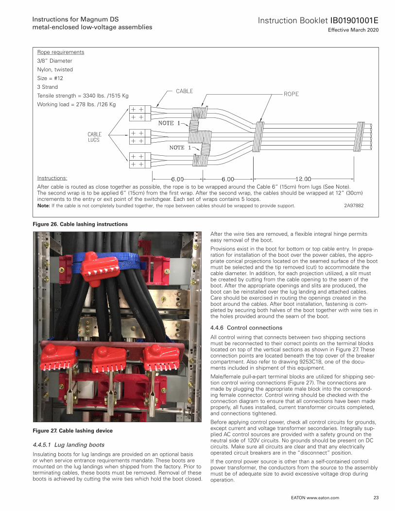
Rope requirements
3/8” Diameter
Nylon, twisted
Size = #12
3 Strand
Tensile strength = 3340 lbs . /1515 Kg
Working load = 278 lbs . /126 Kg
Instructions:
After cable is routed as close together as possible, the rope is to be wrapped around the Cable 6” (15cm) from lugs (See Note) . The second wrap is to be applied 6” (15cm) from the first wrap . After the second wrap, the cables should be wrapped at 12” (30cm) increments to the entry or exit point of the switchgear . Each set of wraps contains 5 loops .
ote: N If the cable is not completely bundled together, the rope between cables should be wrapped to provide support . 2A97882
After the wire ties are removed, a flexible integral hinge permits easy removal of the boot .
Provisions exist in the boot for bottom or top cable entry . In prepa-ration for installation of the boot over the power cables, the appro-priate conical projections located on the seamed surface of the boot must be selected and the tip removed (cut) to accommodate the cable diameter . In addition, for each projection utilized, a slit must be created by cutting from the cable opening to the seam of the boot . After the appropriate openings and slits are produced, the boot can be reinstalled over the lug landing and attached cables . Care should be exercised in routing the openings created in the boot around the cables . After boot installation, fastening is com-pleted by securing both halves of the boot together with wire ties in the holes provided around the seam of the boot .
4.4.6 Control connections
All control wiring that connects between two shipping sections must be reconnected to their correct points on the terminal blocks located on top of the vertical sections as shown in Figure 27 . These connection points are located beneath the top cover of the breaker compartment . Also refer to drawing 9253C18, one of the docu-ments included in shipment of this equipment .
Male/female pull-a-part terminal blocks are utilized for shipping sec-tion control wiring connections (Figure 27) . The connections are made by plugging the appropriate male block into the correspond-ing female connector . Control wiring should be checked with the connection diagram to ensure that all connections have been made properly, all fuses installed, current transformer circuits completed, and connections tightened .
Before applying control power, check all control circuits for grounds, except current and voltage transformer secondaries . Integrally sup-plied AC control sources are provided with a safety ground on the neutral side of 120V circuits . No grounds should be present on DC circuits . Make sure all circuits are clear and that any electrically operated circuit breakers are in the “disconnect” position .
If the control power source is other than a self-contained control power transformer, the conductors from the source to the assembly must be of adequate size to avoid excessive voltage drop during operation .

24
Instruction Booklet IB01901001EEffective March 2020
Instructions for Magnum DS
metal-enclosed low-voltage assemblies
EATON www.eaton.com
4.5 Traveling circuit breaker lifter
The traveling overhead circuit breaker lifter is a standard device installed on outdoor assemblies . Refer to IB01900002E for details regarding outdoor assemblies .
Indoor assemblies are supplied with a traveling overhead lifters as an optional item . When an optional breaker lifter is supplied, it is shipped in a separate carton (w 3) with instructions for assembly .
In general, the installation of the lifter assembly is not difficult . Certain steps should, however, be carefully followed to ensure smooth operation .
For proper installation of the overhead breaker lifter follow the instructions in Figures 29 and 30 . Figure 31 shows how to attach to the breaker for lifting .
m DANGERDO NOT STAND UNDER THE CIRCUIT BREAKER DURING HOISTING OPERA-TIONS. THE CIRCUIT BREAKER MIGHT SLIP AND CAUSE PERSONAL INJURY. KEEP HANDS AND TOOLS AWAY FROM BREAKER LIFTING YOKE, LIFTING HOOKS AND BREAKER. SEVERE INJURY MAY RESULT. SUDDEN MOTIONS ARE COMMON IN A CABLE UNDER TENSION AS IT WINDS AROUND A WINCH DRUM.
4.6 Moving parts
There are few moving parts in the stationary structures of Magnum DS low-voltage assemblies . It is recommended that all moving parts be carefully operated by hand . This will ensure that no binding or damage has occurred during shipment or handling . In some cases, accessories may be blocked or braced for shipment . Thoroughly check apparatus, such as meters and relays, for forms of blocking or bracing which must be removed .
Figure 28 Shipping split control terminal block connection
VIEW A
9253C21
SHIPPING SPLIT SEE VIEW A WIREWAY FOR CONTROL WIRE
REMOVE COVER FOR ACCESSTO TERMINAL BLOCKS
TERMINAL BLOCKS
CONTROL CIRCUIT WIRING CONNECTIONS AT SHIPPINGSPLITS WILL BE MADE WITH PULL-APART TERMINALBLOCKS MOUNTED BELOW THE TOP COVER IN THEBREAKER COMPARTMENT. CONNECTIONS ARE MADEBY PLUGGING PIGTAIL INTO THE ADJACENT ENCLOSURELOCATED ON THE RIGHT. IF THE NUMBER OF CONNECTIONS EXCEEDS THE NUMBER PERMITTED INONE ENCLOSURE, CONNECTIONS WILL CONTINUE TOTHE NEXT ENCLOSURE ON THE RIGHT.

25
Instruction Booklet IB01901001EEffective March 2020
Instructions for Magnum DS
metal-enclosed low-voltage assemblies
EATON www.eaton.com
Figure 29. Breaker lifter installation
2A97859
INSTALLATION INSTRUCTIONS
STEP1- INSTALL WHEEL STOP ON FRONT RAIL AT ONE END OF GEAR.2- PUT HOIST ASSEMBLY ON TOP OF GEAR FROM END OPPOSITE FIRST WHEEL STOP.
(NOTE!!! DO NOT ROLL HOIST ACROSS GEAR UNTIL STEP 1 IS COMPLETED).3- INSTALL SECOND WHEEL STOP ON OPPOSITE END OF GEAR.4- ATTACH BREAKER LIFTING YOKE TO SHACKLE AT END OF WIRE ROPE. (FOLLOW INSTRUCTIONS
ON BREAKER LIFTING YOKE & TABLE 5 FOR PROPER ATTACHMENT LOCATION FOR VARIOUSBREAKERS).

26
Instruction Booklet IB01901001EEffective March 2020
Instructions for Magnum DS
metal-enclosed low-voltage assemblies
EATON www.eaton.com
Figure 30. Breaker lifter installation.
2A97859
FOR SEISMIC APPLICATIONS THEBREAKER LIFTER HOIST SHOULDBE SECURED WHEN NOT IN USE
SEISMIC HOLD DOWN FOR HOIST
Figure 31. Breaker lifting yoke for installing and removing Magnum circuit breakers

27
Instruction Booklet IB01901001EEffective March 2020
Instructions for Magnum DS
metal-enclosed low-voltage assemblies
EATON www.eaton.com
Section 5: Inspection and testing prior to operation
m WARNINGBEFORE PROCEEDING WITH ANY INSTALLATION, TESTING, START-UP OR MAINTENANCE, REVIEW ALL OF SECTION 1 FOR SAFETY PRACTICES AND RECOMMENDATIONS. FAILURE TO DO SO MAY RESULT IN DEATH, SERI-OUS BODILY INJURY OR PROPERTY DAMAGE.
5.1 General information
After the low-voltage assembly and apparatus to be controlled have been installed and all interconnections made, the equipment should be given a final check and tested before being placed in service . This is necessary to assure that the equipment has been correctly installed and that all connections are complete and have been prop-erly made .
m DANGERTO AVOID POSSIBLE DEATH, BODILY INJURY OR ELECTRICAL SHOCK, EXTREME CARE MUST BE EXERCISED TO PREVENT THE EQUIPMENT FROM BEING CONNECTED TO THE POWER SYSTEM WHILE THE PRELIMINARY TESTS ARE BEING CONDUCTED. IF DISCONNECTING SWITCHES ARE NOT AVAILABLE, LINE LEADS SHOULD BE DISCONNECTED TO ACCOMPLISH THIS NECESSARY STEP.
Directions for testing relays, instruments, meters, circuit breakers and other electronic devices, which may be a part of the assem-bly, are given in the instruction book for each individual device . The proper settings for protective devices are normally determined from a coordination study performed by the purchaser or consultant . Factory settings were those used for production testing and do not reflect specific site requirements.
5.2 Test equipment
Test equipment will depend on the rating and type of installation . Portable voltmeters of the multi-scale type will be required . For larg-er installations, ammeters should be available in case unexpected circumstances arise . An ohmmeter and “megger” will prove invalu-able in checking insulation and continuity of the circuits . A simple portable device for “ringing” or “lighting-out” circuits may be used for the continuity check .
5.3 Connections
Wire connections, accessible bolted bus connections and barriers should be examined to be sure that they have not been loosened or damaged during shipment or installation .
The connections to equipment external from the low-voltage assem-bly such as remote control, interlock circuits and auxiliary switches should be checked for continuity to ensure that they are also cor-rect . There must be definite assurance that connections are correct before an attempt is made to operate the equipment .
Verify that all shipping split wiring has been correctly connected .
5.4 Auxiliary equipment
If space heaters are supplied, they should be energized to confirm correct operation .
Relays included on the instrument panels are normally set for pro-duction testing levels when shipped . The final settings of the relays should be coordinated with other parts of the system in accordance with the purchaser’s standards or operation practice . Any necessary modifications to the relay settings should be carried out in accor-dance with the instruction leaflet for that particular relay .
All covers for meters, relays and other devices removed during test-ing, should be carefully handled when removed . The covers should be put back in place promptly to keep dust and dirt from collecting .
5.5 Ground fault systems (per the National Electric Code)
Ground fault protection of service entrance equipment shall be provided for solidly grounded wye electrical services of more than 150 volts to ground, but not exceeding 600 volts phase-to-phase, for each service disconnecting means rated 1000 amperes or more . The ground fault protection system shall be performance tested when first installed on site . The test shall be conducted in accordance with instructions outlined in Article 230 .95 of the National Electrical Code .
Performance testing of ground fault protection systems should be undertaken only by qualified personnel . In the tests requiring the use of high current test equipment, it is usually necessary to obtain the services of a qualified testing organization . See IB 32-693 for Magnum DS breaker ground fault conformance testing .
5.6 Electric and arc flash hazard
NEC Article 110 .16 requires that low-voltage switchgear be marked to indicate the potential for electric and arc flash hazard . Labels to this affect are to be applied at the installation site prior to energizing the equipment . Two labels are supplied and are contained in the doc-ument sleeve mounted on the side of the equipment . One label is to be applied on the front and the other on the rear of the equipment .
5.7 Circuit breakers and trip units
All circuit breakers should be checked to be sure that they are in accordance with the requirements of the circuits . The circuit break-ers and associated safety interlocks should have been checked mechanically during the equipment installation phase . This was, however, only preliminary and a more detailed inspection and test-ing procedure, both electrical and mechanical, must take place prior to putting the equipment into service . For information on complete testing and maintenance of the circuit breakers and trip units, refer to the separate circuit breaker and trip unit instruction manuals .
5.8 Baseline test data
Certain baseline tests should be preformed and recorded for diagnostic maintenance purposes . Take “megger” readings again between the buses and ground and between phases . Keep a record of these readings for future reference in determining when trends occur that would indicate an increase of resistance .
A one-minute dielectric test was preformed on all bus at the fac-tory in accordance with ANSI C37 .20 .1 . Repeating these tests is not required for field installation unless the equipment has been in extended or outdoor storage, or major bus modifications have been made . If required, 2200 Vac should be applied between each phase, and each phase-to-ground . All connections to the bus from control power or metering circuits must first be isolated from the bus . Circuits breakers must be in the disconnect or removed position . Devices such as lightening arresters and capacitors must also be disconnected .
5.9 Final steps
m DANGERENERGIZING THE SWITCHGEAR FOR THE FIRST TIME IS POTENTIALLY DANGEROUS. THEREFORE, ONLY QUALIFIED PERSONNEL SHOULD BE PRESENT WHEN THE EQUIPMENT IS ENERGIZED. IF PROBLEMS CAUSED BY DAMAGE OR POOR INSTALLATION PRACTICES HAVE NOT BEEN DETECTED IN THE CHECKOUT PROCEDURE (PREVIOUSLY DESCRIBED), DEATH, PERSONAL INJURY OR SERIOUS DAMAGE MAY RESULT WHEN POWER IS APPLIED.

28
Instruction Booklet IB01901001EEffective March 2020
Instructions for Magnum DS
metal-enclosed low-voltage assemblies
EATON www.eaton.com
Before energizing, another thorough check should be made using the following checklist .
1 . Have circuit breakers and other operation mechanisms been exer-cised?
2 . Has electrical insulation resistance been tested phase-to-phase and phase-to-ground? Record these readings for future reference .
3 . Have relay, meter and instrument connections been checked?
4 . Have the electrically operated mechanisms of all circuit breakers been checked?
5 . Has the ground fault protection system been checked in accor-dance with the National Electrical Code?
6 . Are the adjustable trip units properly set?
7 . Is all field wiring secured and not in contact with live bus?
8 . Are all grounding connections properly made?
9 . Has an inspection been performed to ensure that all debris, dirt, tools, scrap wire, and any other foreign objects were removed and that all vent openings are free from obstructions?
10 . Have all barriers and covers been replaced and doors closed and latched?
11 . Turn all circuit breakers to the OFF position before energizing the bus .
12 . Electrically-operated breakers:
Have all breakers in the disconnected position . Rack each breaker in one at a time after the assembly is energized . This way only one breaker will be electrically charged at a time . This is done so that control circuit fuses are not overloaded by all breakers charg-ing at the same time .
Section 6: Periodic inspection and testing6.1 General information
m WARNINGBEFORE PROCEEDING WITH ANY INSTALLATION, TESTING, START-UP OR MAINTENANCE, REVIEW ALL OF SECTION 1 FOR SAFETY PRACTICES AND RECOMMENDATIONS. FAILURE TO DO SO MAY RESULT IN DEATH, SERI-OUS BODILY INJURY OR PROPERTY DAMAGE.
m DANGERWHEN INSPECTING, REPAIRING AND PERFORMING MAINTENANCE ON A MAGNUM DS SWITCHGEAR OR SWITCHBOARD ASSEMBLY, THE FACT THAT DANGEROUS VOLTAGES MAY EXIST MUST BE KEPT IN MIND. PRE-CAUTIONS MUST BE TAKEN TO ENSURE THAT PERSONNEL DO NOT COME IN CONTACT WITH ENERGIZED PARTS. FAILURE TO DO SO MAY RESULT IN DEATH, PERSONAL INJURY OR ELECTRICAL SHOCK.
Some common general precautions for primary power circuits are:
1 . All connections should be considered energized until the crew expecting to work on them is assured that the circuits are de-energized, and all precautions have been taken to ensure that there is no chance of a circuit being energized after work is underway .
2 . Breakers which have been opened to de-energize a circuit to per-mit work on the equipment should be locked open and a suitable visible warning device placed on them .
3 . Do not work on parts normally carrying high current until they have been disconnected from the system and connected to the ground bus . When performing maintenance, provisions should be made for connecting adequate flexible ground leads to every part of the switching equipment .
4 . A good and reliable ground connection is necessary for every switchgear or switchboard assembly installation . This ground connection should be of sufficient capacity to take care of any abnormal condition that might occur on the system and should be independent of the grounds used for any other apparatus .
6.2 Access to switchgear assembly parts
6.2.1 Main bus and cable compartment
A Magnum DS metal-enclosed low-voltage assembly is designed so that internal compartments provide isolation between the circuit breaker compartment and the main bus compartment . Access to high current parts is provided by removable covers and barriers .
m DANGERBARRIERS AND COVERS SHOULD NOT BE REMOVED UNLESS THE PARTS TO BE EXPOSED ARE DE-ENERGIZED. ADDITIONALLY, BE CERTAIN THAT ALL BARRIERS AND COVERS ARE PROPERLY REPLACED IMMEDIATELY UPON CONCLUSION OF MAINTENANCE OR INSPECTION PROCEDURES. FAILURE TO DO SO MAY CAUSE DEATH, BODILY INJURY OR PROPERTY DAMAGE.

29
Instruction Booklet IB01901001EEffective March 2020
Instructions for Magnum DS
metal-enclosed low-voltage assemblies
EATON www.eaton.com
6.2.2 drawout main disconnecting contacts and current transformers
The primary stationary disconnecting contacts and ringtype current transformers are located on the breaker cell rear wall . These con-tacts and transformers are easily exposed unless provided with an optional safety shutter system .
m DANGERBE EXTREMELY CAREFUL NOT TO TOUCH ANY CONTACTS OR TRANSFORMERS UNLESS ALL UPPER AND LOWER HIGH CURRENT PARTS ARE DE-ENERGIZED. FAILURE TO DO SO MAY CAUSE DEATH, PERSONAL INJURY OR ELECTRICAL SHOCK.
6.2.3 Control equipment
With the exception of apparatus such as current transformers and space heaters, control equipment is generally accessible without exposing high voltage parts .
6.3 Inspection and maintenance schedule
To assure high quality service, a definite maintenance schedule is essential . Plant operation and local conditions vary to such an extent that the schedule should be tailored to the conditions . The following general requirements should be helpful in establishing a program .
m DANGERWHEN ENERGIZED, A CIRCUIT BREAKER IS PART OF A HIGH POWER SYSTEM. BEFORE ATTEMPTING ANY INSPECTION OR MAINTENANCE, BE SURE THAT ALL PRIMARY AND CONTROL CIRCUITS HAVE BEEN DE-ENERGIZED AND GROUNDED AS REQUIRED. ALSO MAKE CERTAIN THAT PROPER STEPS HAVE BEEN TAKEN TO BE SURE THAT THEY WILL REMAIN DE-ENERGIZED UNTIL ALL WORK IS COMPLETED. FAILURE TO DO SO MAY RESULT IN DEATH, BODILY INJURY OR ELECTRICAL SHOCK.
6.3.1 Individual devices
The maintenance schedule for individual devices, such as circuit breakers, relays and instruments, should be based first on the rec-ommendations contained in their individual instruction books . These operations should be coordinated with the overall program to result in the least operating inconvenience and circuit shutdown .
6.3.2 Overall assembly maintenance
When operating and local conditions are normal, the switchgear assembly should be given a thorough overall maintenance check at least annually . Where abnormal conditions exist, more frequent inspection and maintenance is necessary .
6.3.3 Buses and connections
De-energize primary circuits and remove barriers from primary com-partments . Before cleaning, record “megger” readings between phases and to ground . Inspect for signs of overheating or weakened insulation . Remove as much dirt, dust and other foreign material as possible from the insulation and conductors with minimum exposure to any solvents . The recommended cleaning procedure is to use an industrial quality vacuum cleaner and/or a lint-free cloth . In most cases, this will be sufficient . For accumulations which cannot be removed by the above procedure, a lint-free cloth slightly dampened with water can be used . Allow the switchgear apparatus to dry for at least four hours at room temperature before energizing . If this procedure does not produce satisfactory results, use lint-free cloth dampened with a mild solvent, such as mineral spirits, Stoddard solvent, or isopropyl alcohol . Dry the same as when using a water dampened cloth .
m CAUTIONTHE MILD SOLVENTS DESCRIBED ARE FLAMMABLE. PROVIDE ADEQUATE VENTILATION AND KEEP AWAY FROM FLAMES AND OTHER IGNITION SOURCES. CONSULT YOUR SAFETY DEPARTMENT BEFORE USING.
After buses and insulation have been dusted, wiped clean, and dried, take “megger” readings again between the buses and ground and between phases . Keep a record of these readings for future reference in determining when trends occur that would indicate an increase of resistance .
A one-minute dielectric test was preformed on all bus at the fac-tory in accordance with ANSI C37 .20 .1 . Repeating these tests is not required for field installation unless the equipment has been in extended or outdoor storage, or major bus modifications have been made . If required, 2200 Vac should be applied between each phase, and each phase-to-ground . All connections to the bus from control power or metering circuits must first be isolated from the bus . Circuits breakers must be in the disconnect or removed position . Devices such as lightening arresters and capacitors must also be disconnected .
6.3.4 Drawout main disconnecting contacts and supports
Remove each breaker from its cell . Remember, all circuits should be de-energized . Expose primary contacts and their supports . Inspect for abnormal wear or overheating . Discoloration of the surface is not harmful unless corrosion due to atmospheric conditions is severe, leaving deposits on the surface . Follow the cleaning instructions outlined in Section 6 .3 .3 . Check each breaker while it is out of the housing for all items recommended in the instruction book applying to the breaker .
6.3.5 Instruments, relays and other panel devices
Individual devices should be maintained according to the specific instructions supplied for each device . Remove relay covers and inspect interiors for dust or dirt . All devices should be checked for correct operation .
6.3.6 Secondary wiring, blocks and connections
Check all wiring connections for tightness, including those at the current and voltage transformers and at the terminal blocks where circuits leave the assembly . Make sure that all transformer second-ary wiring connections are properly connected to the assembly ground bus where so indicated . Visually inspect control circuit sec-ondary contact blocks, both fixed in the cell and moveable on the breaker, for abnormal signs of wear, fatigue or overheating .
6.3.7 Mechanical parts
Visually check and manually operate mechanical moving parts, such as cell switches, position interlocks, cell protective shutters (when provided), door latches/hinges, and drawout rails .
6.3.8 Ventilation
Check all air passages and intakes for obstructions and accumula-tions of dirt . When filters are used, replace or clean when dirty .
6.3.9 Records
The condition of each vertical section at the time of inspection should be listed in a permanent record to become a guide for antici-pating the need for replacements or for special attention between regular maintenance periods .

30
Instruction Booklet IB01901001EEffective March 2020
Instructions for Magnum DS
metal-enclosed low-voltage assemblies
EATON www.eaton.com
6.3.10 Abnormal conditions
Type Magnum DS switchgear and switcboard assemblies have been designed for “NORMAL” operating conditions as defined in ANSI C37 .20 .1 . Local conditions such as high humidity, salt-laden atmo-sphere, corrosive gases, heavy dust, or severe circuit operating con-ditions are considered to be abnormal . Any of these conditions will require more frequent inspections .
It should be emphasized that a series of quarterly inspections are advisable until the progressive facts of the local conditions can be analyzed to determine a schedule which will maintain equipment in satisfactory condition .
In some locations, conditions may be so bad that the frequency of maintenance will interfere with operation and production schedules . In such cases, consideration should be given to the possibility of enclosing the low-voltage assembly in a relatively air tight room . If this approach is followed, a sufficient quantity of clean air must be supplied to the room to ensure that a positive pressure is main-tained in the room . Under such conditions, a more normal mainte-nance schedule can be established . Such an arrangement could also provide for cooling the air where the ambient temperature is rela-tively high, further improving operation conditions .
m CAUTIONFAILURE TO INSPECT, CLEAN, LUBRICATE AND MAINTAIN THE SWITCHGEAR ASSEMBLY AT RECOMMENDED FREQUENCIES COULD RESULT IN FAILURE OF THE EQUIPMENT TO OPERATE PROPERLY UNDER FAULT CONDITIONS.
6.3.11 Lubrication
A metal-enclosed low-voltage assembly is designed so that lubri-cation is not required under normal conditions . Abnormal local conditions, such as high humidity, salt-laden atmosphere, corrosive gases, or severe circuit operating conditions, may demand the use of lubricants . In such cases, a dry or powder lubricant may be used on moving or mating mechanical parts, and a thin film of light-weight grease on disconnecting contacts . The application of the lubricants should be held to minimum to reduce the accumulation of dust and dirt . During routine maintenance old lubricants should be wiped off before fresh lubricants are applied .
6.3.12 Renewal parts
When ordering renewal or spare parts, include as much informa-tion as possible . In many cases, the style number of the new part can be obtained from identification on the old part . Always include a description of the old part . Specify the rating, vertical section and compartment number . Always supply the general order number and/or the shop order number of the assembly itself .
Section 7: Document references7.1 Instruction books and drawings
In addition to this instruction book, the following Instruction books and drawings are commonly included in any low-voltage assembly shipment . Please inspect the packet attached to the outside, or within an empty cell, for all pertinent documentation before contact-ing an Eaton service representative for replacements .
2A97855 Magnum DS structure section view type DS low-voltage metal-enclosed switchgear
4A37896 Magnum DS structure base plan
9253C18 Shipping split bus information
9253C21 Installation space requirements
In addition, the following documents may be included depending upon optional equipment contained within the assembly:
2A97859 Overhead lifter installation instructions
IL019116EN Installation guidelines for users of Magnum DS low-voltage rear/front access switchgear assem-blies for seismic applications
IB2C12060H12 Magnum low voltage power circuit breakers user manual (DS, DC, DSX, DSL, and MDE)
IB2C12063H03 Instructions for installation, operation and mainte-nance of Magnum SB insulated case low voltage power circuit breakers
32-693A Instructions for field testing of ground fault sys-tems utilizing Eaton Magnum DS circuit breakers
IL019226EN C-HRG technical information and adjustment procedure
52-01-TE Instructions for Eaton type CM52 network protec-tors 800 to 4500 amperes
MN01301001E Instructions for installation, operation and mainte-nance of Series NRX low voltage power (air) circuit breakers
7.2 Addendums
This Instruction book is supplemented by the following, which may be included if that particular option is present within the assembly . These documents do not “stand alone” but are supplemental infor-mation that builds upon the standard information contained within this instruction book .
IB01900001E Instructions for Magnum DS metal-enclosed low-voltage arc-resistant assemblies
IB01900002E Instructions for Magnum DS metal-enclosed low-voltage outdoor (NEMA 3R) assemblies
Also, supporting documentation and instructions for auxiliary compo-nents and devices contained within the assembly will be forwarded with any shipment . The accuracy of claims made within documents by other manufacturers is not the responsibility of Eaton but the device manufacturer .
There are numerous supporting documents which are not listed here due to the wide variety of components contained within any given assembly . For a full selection of available documents, see the Technical documents section of www .Eaton .com .

31
Instruction Booklet IB01901001EEffective March 2020
Instructions for Magnum DS
metal-enclosed low-voltage assemblies
EATON www.eaton.com
Ground fault test recordGround fault test record should be retained by those in charge of the building’s electrical
Installation in order to be available to the authority having jurisdiction.(See Article 5.5 in this Instruction)
Test date Circuit breaker No. Results Tested by

32
Instruction Booklet IB01901001EEffective March 2020
Instructions for Magnum DS
metal-enclosed low-voltage assemblies
EATON www.eaton.com
For renewal parts information call your local authorized Eaton Distributor . For the name of the nearest Eaton distributor,
Please call:
1-800-525-2000
To assure safety of operation and continuity of service, always use genuine Eaton aftermarket parts and product upgrades .
Should you need factory assistance on this Magnum DS low-voltage assembly or options for upgrading your other low-voltage assemblies products,
Call:
1-800-BKR-FAST
(1-800-257-3278)

33
Instruction Booklet IB01901001EEffective March 2020
Instructions for Magnum DS
metal-enclosed low-voltage assemblies
EATON www.eaton.com
Notes:

34
Instruction Booklet IB01901001EEffective March 2020
Instructions for Magnum DS
metal-enclosed low-voltage assemblies
EATON www.eaton.com
Notes:

35
Instruction Booklet IB01901001EEffective March 2020
Instructions for Magnum DS
metal-enclosed low-voltage assemblies
EATON www.eaton.com
Notes:

Instruction Booklet IB01901001EEffective March 2020
Instructions for Magnum DS
metal-enclosed low-voltage assemblies
EatonElectrical Sector1000 Eaton Boulevard.Cleveland, OH 44122United States877-ETN-CARE (877-386-2273)Eaton.com
© 2020 EatonAll Rights ReservedPrinted in USAPublication No. IB01901001E / TBG000569March 2020
Eaton is a registered trademark.
All other trademarks are property of their respective owners.
The sale of the product shown in this literature is subject to the terms and conditions outlined in appropriate Eaton selling policies or other contractual agreement between the parties . This literature is not intended to and does not enlarge or add to any such contract . The sole source governing the rights and remedies of any purchaser of this equipment is the contract between the purchaser and Eaton .
NO WARRANTIES, EXPRESSED OR IMPLIED, INCLUDING WARRANTIES OF FITNESS FOR A PARTICULAR PURPOSE OR MERCHANTABILITY, OR WARRANTIES ARISING FROM COURSE OF DEALING OR USAGE OF TRADE, ARE MADE REGARDING THE INFORMATION, RECOMMENDATIONS, AND DESCRIPTIONS CONTAINED HEREIN.
In no event will Eaton be responsible to the purchaser or user in contract, in tort (including negligence), strict liability or otherwise for any special, indirect, incidental or consequential damage or loss whatsoever, including but not limited to damage or loss of use of equipment, plant or power system, cost of capital, loss of power, additional expenses in the use of existing power facilities, or claims against the purchaser or user by its customers resulting from the use of the information, recommendations and description contained herein .