Embed Size (px)
Citation preview
SUPER AE
Low Voltage Switchgears
User´s Manual
AE1000 – 6300-SSAE4000-SSA/SSCAE1000 – 3200-SH
MITSUBISHI ELECTRICArt. no.: 6964706 12 2002Version C
MITSUBISHI ELECTRIC
INDUSTRIAL AUTOMATION

About this Manual
The texts, illustrations, diagrams and examples in this manual are only intended ashelp for the installation, handling and operation of the low voltage air circuit breakers
of the SUPER AE series.
If you have any questions regarding the installation and operation of the equipmentdescribed in this manual, please do not hesitate to contact your sales office or one of
your Mitsubishi distribution partners (see cover page).
You can also obtain information updates and answers to frequently asked questionsfrom our Internet website:
http://www.mitsubishi-automation.com
No part of this manual may be reproduced, copied, stored in any kind of informationretrieval system or distributed without the prior express written consent of
MITSUBISHI ELECTRIC EUROPE B.V.
MITSUBISHI ELECTRIC EUROPE B.V. reserves the right to change thespecifications of its products and/or the contents of this manual at any time and
without prior notice.
© 12/2002

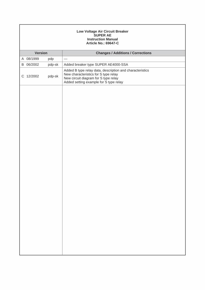
Low Voltage Air Circuit BreakerSUPER AE
Instruction ManualArticle No.: 69647-C
Version Changes / Additions / Corrections
A 08/1999 pdp —
B 06/2002 pdp-sk Added breaker type SUPER AE4000-SSA
C 12/2002 pdp-sk
Added B type relay data, description and characteristicsNew characteristics for S type relayNew circuit diagram for S type relayAdded setting example for S type relay

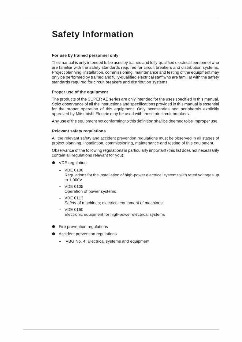
Safety Information
For use by trained personnel only
This manual is only intended to be used by trained and fully-qualified electrical personnel whoare familiar with the safety standards required for circuit breakers and distribution systems.Project planning, installation, commissioning, maintenance and testing of the equipment mayonly be performed by trained and fully-qualified electrical staff who are familiar with the safetystandards required for circuit breakers and distribution systems.
Proper use of the equipment
The products of the SUPER AE series are only intended for the uses specified in this manual.Strict observance of all the instructions and specifications provided in this manual is essentialfor the proper operation of this equipment. Only accessories and peripherals explicitlyapproved by Mitsubishi Electric may be used with these air circuit breakers.
Any use of the equipment not conforming to this definition shall be deemed to be improper use.
Relevant safety regulations
All the relevant safety and accident prevention regulations must be observed in all stages ofproject planning, installation, commissioning, maintenance and testing of this equipment.
Observance of the following regulations is particularly important (this list does not necessarilycontain all regulations relevant for you):
VDE regulation
– VDE 0100Regulations for the installation of high-power electrical systems with rated voltages upto 1,000V
– VDE 0105Operation of power systems
– VDE 0113Safety of machines; electrical equipment of machines
– VDE 0160Electronic equipment for high-power electrical systems
Fire prevention regulations
Accident prevention regulations
– VBG No. 4: Electrical systems and equipment
Danger symbolsIn this manual, warnings of hazards and potential problems are identified with the followingtwo symbols:
PDANGER:This symbol indicates that failure to observe the safety procedures described can re-sult in severe electrical shock hazards that can cause serious injury to the operatingstaff. In some case, such a hazard can also be lethal.
ECAUTION:Failure to observe the procedures identified by this symbol can result in incorrect set-tings or damage to the equipment or other property.
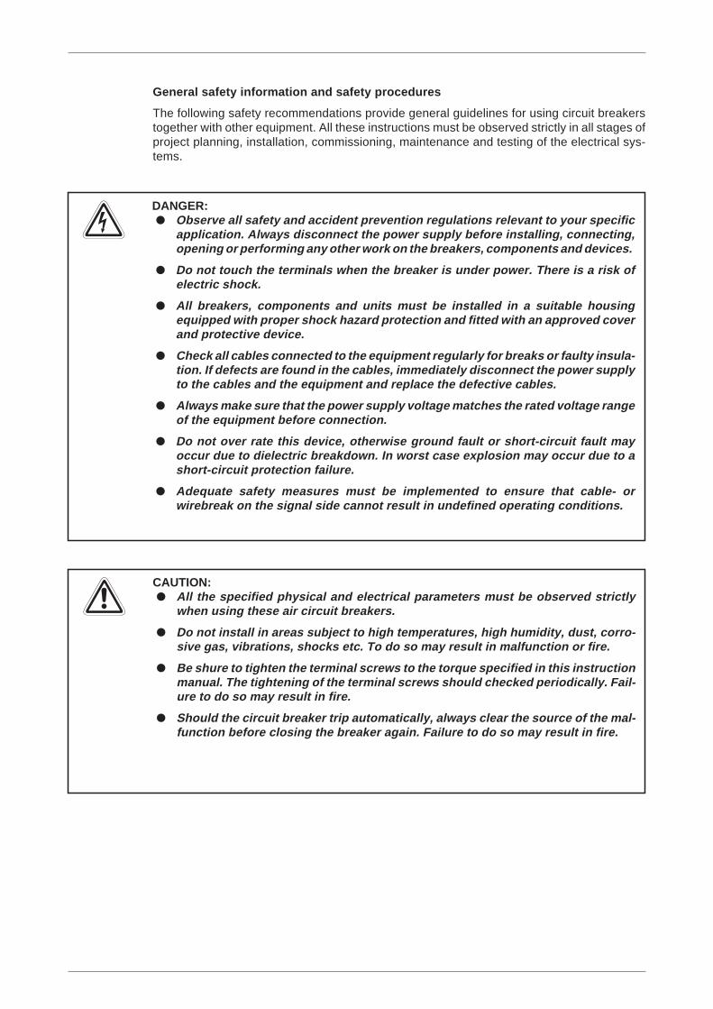
General safety information and safety procedures
The following safety recommendations provide general guidelines for using circuit breakerstogether with other equipment. All these instructions must be observed strictly in all stages ofproject planning, installation, commissioning, maintenance and testing of the electrical sys-tems.
PDANGER:
ECAUTION: All the specified physical and electrical parameters must be observed strictly
when using these air circuit breakers.
Do not install in areas subject to high temperatures, high humidity, dust, corro-sive gas, vibrations, shocks etc. To do so may result in malfunction or fire.
Be shure to tighten the terminal screws to the torque specified in this instructionmanual. The tightening of the terminal screws should checked periodically. Fail-ure to do so may result in fire.
Should the circuit breaker trip automatically, always clear the source of the mal-function before closing the breaker again. Failure to do so may result in fire.
Observe all safety and accident prevention regulations relevant to your specificapplication. Always disconnect the power supply before installing, connecting,opening or performing any other work on the breakers, components and devices.
Do not touch the terminals when the breaker is under power. There is a risk ofelectric shock.
All breakers, components and units must be installed in a suitable housingequipped with proper shock hazard protection and fitted with an approved coverand protective device.
Check all cables connected to the equipment regularly for breaks or faulty insula-tion. If defects are found in the cables, immediately disconnect the power supplyto the cables and the equipment and replace the defective cables.
Always make sure that the power supply voltage matches the rated voltage rangeof the equipment before connection.
Do not over rate this device, otherwise ground fault or short-circuit fault mayoccur due to dielectric breakdown. In worst case explosion may occur due to ashort-circuit protection failure.
Adequate safety measures must be implemented to ensure that cable- orwirebreak on the signal side cannot result in undefined operating conditions.

Contents
1 Introduction
1.1 External View . . . . . . . . . . . . . . . . . . . . . . . . . . . . . . . . . . . . . . . . . . . . . . . . . . . . 1-1
1.1.1 AE1000–AE3200-SS – Fixed Type. . . . . . . . . . . . . . . . . . . . . . . . . . . . . 1-1
1.1.2 AE1000–AE3200-SS – Drawout type . . . . . . . . . . . . . . . . . . . . . . . . . . . 1-2
1.1.3 AE1000–AE3200-SH – Drawout type . . . . . . . . . . . . . . . . . . . . . . . . . . . 1-3
1.1.4 AE4000–AE6300-SS – Drawout type . . . . . . . . . . . . . . . . . . . . . . . . . . . 1-4
1.2 Internal construction . . . . . . . . . . . . . . . . . . . . . . . . . . . . . . . . . . . . . . . . . . . . . . . 1-5
2 Set-up
2.1 Unpacking. . . . . . . . . . . . . . . . . . . . . . . . . . . . . . . . . . . . . . . . . . . . . . . . . . . . . . . 2-1
2.2 Handling . . . . . . . . . . . . . . . . . . . . . . . . . . . . . . . . . . . . . . . . . . . . . . . . . . . . . . . . 2-2
2.3 Dimensions . . . . . . . . . . . . . . . . . . . . . . . . . . . . . . . . . . . . . . . . . . . . . . . . . . . . . . 2-4
2.3.1 Fixed types AE1000–AE3200-SS/SH . . . . . . . . . . . . . . . . . . . . . . . . . . . 2-4
2.3.2 Drawout types AE1000–AE3200-SS. . . . . . . . . . . . . . . . . . . . . . . . . . . . 2-5
2.3.3 Drawout types AE1000–AE3200-SH. . . . . . . . . . . . . . . . . . . . . . . . . . . . 2-6
2.3.4 Fixed types AE4000–SSA. . . . . . . . . . . . . . . . . . . . . . . . . . . . . . . . . . . . 2-7
2.3.5 Drawout types AE4000–SSA . . . . . . . . . . . . . . . . . . . . . . . . . . . . . . . . . 2-8
2.3.6 Fixed types AE4000–SSC. . . . . . . . . . . . . . . . . . . . . . . . . . . . . . . . . . . . 2-9
2.3.7 Drawout types AE4000–SSC . . . . . . . . . . . . . . . . . . . . . . . . . . . . . . . . . 2-9
2.3.8 Drawout types AE4000–AE6000-SS. . . . . . . . . . . . . . . . . . . . . . . . . . . 2-10
2.4 Weight. . . . . . . . . . . . . . . . . . . . . . . . . . . . . . . . . . . . . . . . . . . . . . . . . . . . . . . . . 2-11
2.4.1 Standard series . . . . . . . . . . . . . . . . . . . . . . . . . . . . . . . . . . . . . . . . . . . 2-11
2.4.2 High-performance series . . . . . . . . . . . . . . . . . . . . . . . . . . . . . . . . . . . . 2-11
2.5 Storage . . . . . . . . . . . . . . . . . . . . . . . . . . . . . . . . . . . . . . . . . . . . . . . . . . . . . . . . 2-12
2.6 Installation. . . . . . . . . . . . . . . . . . . . . . . . . . . . . . . . . . . . . . . . . . . . . . . . . . . . . . 2-13
2.6.1 Fixed types . . . . . . . . . . . . . . . . . . . . . . . . . . . . . . . . . . . . . . . . . . . . . . 2-13
2.6.2 Drawout type . . . . . . . . . . . . . . . . . . . . . . . . . . . . . . . . . . . . . . . . . . . . . 2-14
2.7 Connections . . . . . . . . . . . . . . . . . . . . . . . . . . . . . . . . . . . . . . . . . . . . . . . . . . . . 2-18
2.7.1 Main connectors . . . . . . . . . . . . . . . . . . . . . . . . . . . . . . . . . . . . . . . . . . 2-18
2.7.2 Electromagnetic force . . . . . . . . . . . . . . . . . . . . . . . . . . . . . . . . . . . . . . 2-20
2.8 Wiring diagram . . . . . . . . . . . . . . . . . . . . . . . . . . . . . . . . . . . . . . . . . . . . . . . . . . 2-21
2.8.1 Diagram due to terminal designation. . . . . . . . . . . . . . . . . . . . . . . . . . . 2-21
2.8.2 Diagram according to EN50005 . . . . . . . . . . . . . . . . . . . . . . . . . . . . . . 2-23
2.9 Charging operation . . . . . . . . . . . . . . . . . . . . . . . . . . . . . . . . . . . . . . . . . . . . . . . 2-25
2.9.1 Manual charging . . . . . . . . . . . . . . . . . . . . . . . . . . . . . . . . . . . . . . . . . . 2-25
2.9.2 Motor charging . . . . . . . . . . . . . . . . . . . . . . . . . . . . . . . . . . . . . . . . . . . 2-25
2.10 Opening / closing operation . . . . . . . . . . . . . . . . . . . . . . . . . . . . . . . . . . . . . . . . 2-27
2.10.1 Manual operation . . . . . . . . . . . . . . . . . . . . . . . . . . . . . . . . . . . . . . . . . 2-27
2.10.2 Electrical operation . . . . . . . . . . . . . . . . . . . . . . . . . . . . . . . . . . . . . . . . 2-28
2.11 Operation of the drawout mechanism. . . . . . . . . . . . . . . . . . . . . . . . . . . . . . . . . 2-29
2.11.1 Drawout operation. . . . . . . . . . . . . . . . . . . . . . . . . . . . . . . . . . . . . . . . . 2-29
2.11.2 Insert operation . . . . . . . . . . . . . . . . . . . . . . . . . . . . . . . . . . . . . . . . . . . 2-30
3 Operation
3.1 Setting the operating characteristics. . . . . . . . . . . . . . . . . . . . . . . . . . . . . . . . . . . 3-1
3.1.1 Setting procedure . . . . . . . . . . . . . . . . . . . . . . . . . . . . . . . . . . . . . . . . . . 3-1
3.1.2 Sealing . . . . . . . . . . . . . . . . . . . . . . . . . . . . . . . . . . . . . . . . . . . . . . . . . . 3-3
3.1.3 Resetting the indicator. . . . . . . . . . . . . . . . . . . . . . . . . . . . . . . . . . . . . . . 3-3
3.1.4 Characteristics setting for the S type. . . . . . . . . . . . . . . . . . . . . . . . . . . . 3-4
3.1.5 Characteristics setting for the M type . . . . . . . . . . . . . . . . . . . . . . . . . . . 3-6
3.1.6 Characteristics setting for the B type. . . . . . . . . . . . . . . . . . . . . . . . . . . . 3-8
3.1.7 Setting example for S Type – General use . . . . . . . . . . . . . . . . . . . . . . 3-10
3.1.8 Operating system of each device . . . . . . . . . . . . . . . . . . . . . . . . . . . . . 3-12
3.2 Checking the tripping characteristics . . . . . . . . . . . . . . . . . . . . . . . . . . . . . . . . . 3-14
3.2.1 Checking with a field tester (Y-160 and Y-2000). . . . . . . . . . . . . . . . . . 3-14
3.2.2 Checking with the Y-160 . . . . . . . . . . . . . . . . . . . . . . . . . . . . . . . . . . . . 3-15
3.2.3 Checking with the Y-2000 . . . . . . . . . . . . . . . . . . . . . . . . . . . . . . . . . . . 3-18
4 Accessories
4.1 Preparing the breaker . . . . . . . . . . . . . . . . . . . . . . . . . . . . . . . . . . . . . . . . . . . . . . 4-1
4.1.1 Overwiew. . . . . . . . . . . . . . . . . . . . . . . . . . . . . . . . . . . . . . . . . . . . . . . . . 4-2
4.2 Auxiliary switch (AX) . . . . . . . . . . . . . . . . . . . . . . . . . . . . . . . . . . . . . . . . . . . . . . . 4-3
4.2.1 Removal . . . . . . . . . . . . . . . . . . . . . . . . . . . . . . . . . . . . . . . . . . . . . . . . . 4-3
4.2.2 Installation . . . . . . . . . . . . . . . . . . . . . . . . . . . . . . . . . . . . . . . . . . . . . . . . 4-4
4.3 Shunt trip device (SHT) . . . . . . . . . . . . . . . . . . . . . . . . . . . . . . . . . . . . . . . . . . . . 4-5
4.3.1 Removal . . . . . . . . . . . . . . . . . . . . . . . . . . . . . . . . . . . . . . . . . . . . . . . . . 4-5
4.3.2 Installation . . . . . . . . . . . . . . . . . . . . . . . . . . . . . . . . . . . . . . . . . . . . . . . . 4-5
4.4 Closing coil (CC). . . . . . . . . . . . . . . . . . . . . . . . . . . . . . . . . . . . . . . . . . . . . . . . . . 4-6
4.4.1 Removal . . . . . . . . . . . . . . . . . . . . . . . . . . . . . . . . . . . . . . . . . . . . . . . . . 4-6
4.4.2 Installation . . . . . . . . . . . . . . . . . . . . . . . . . . . . . . . . . . . . . . . . . . . . . . . . 4-6
4.5 Undervoltage trip device (UVT) . . . . . . . . . . . . . . . . . . . . . . . . . . . . . . . . . . . . . . 4-7
4.5.1 Removal of the coil . . . . . . . . . . . . . . . . . . . . . . . . . . . . . . . . . . . . . . . . . 4-7
4.5.2 Installation of the coil. . . . . . . . . . . . . . . . . . . . . . . . . . . . . . . . . . . . . . . . 4-7
4.5.3 Removal of the controller . . . . . . . . . . . . . . . . . . . . . . . . . . . . . . . . . . . . 4-8
4.5.4 Installation of the controller . . . . . . . . . . . . . . . . . . . . . . . . . . . . . . . . . . . 4-8
4.6 Motor charging device (MD) . . . . . . . . . . . . . . . . . . . . . . . . . . . . . . . . . . . . . . . . 4-10
4.6.1 Removal . . . . . . . . . . . . . . . . . . . . . . . . . . . . . . . . . . . . . . . . . . . . . . . . 4-10
4.6.2 Installation . . . . . . . . . . . . . . . . . . . . . . . . . . . . . . . . . . . . . . . . . . . . . . . 4-11
4.7 Cell switch (CL). . . . . . . . . . . . . . . . . . . . . . . . . . . . . . . . . . . . . . . . . . . . . . . . . . 4-13
4.7.1 Removal . . . . . . . . . . . . . . . . . . . . . . . . . . . . . . . . . . . . . . . . . . . . . . . . 4-13
4.7.2 Installation . . . . . . . . . . . . . . . . . . . . . . . . . . . . . . . . . . . . . . . . . . . . . . . 4-13
4.7.3 Mounting of the CL adaptor. . . . . . . . . . . . . . . . . . . . . . . . . . . . . . . . . . 4-14
4.8 Cylinder lock (CYL). . . . . . . . . . . . . . . . . . . . . . . . . . . . . . . . . . . . . . . . . . . . . . . 4-15
4.8.1 Removal . . . . . . . . . . . . . . . . . . . . . . . . . . . . . . . . . . . . . . . . . . . . . . . . 4-15
4.8.2 Installation . . . . . . . . . . . . . . . . . . . . . . . . . . . . . . . . . . . . . . . . . . . . . . . 4-15
4.9 Castell lock (CAL) . . . . . . . . . . . . . . . . . . . . . . . . . . . . . . . . . . . . . . . . . . . . . . . . 4-16
4.9.1 Removal . . . . . . . . . . . . . . . . . . . . . . . . . . . . . . . . . . . . . . . . . . . . . . . . 4-16
4.9.2 Installation . . . . . . . . . . . . . . . . . . . . . . . . . . . . . . . . . . . . . . . . . . . . . . . 4-16
4.10 Counter (CNT) . . . . . . . . . . . . . . . . . . . . . . . . . . . . . . . . . . . . . . . . . . . . . . . . . . 4-17
4.11 Safety shutter (SST) . . . . . . . . . . . . . . . . . . . . . . . . . . . . . . . . . . . . . . . . . . . . . . 4-18
4.11.1 Operation and handling. . . . . . . . . . . . . . . . . . . . . . . . . . . . . . . . . . . . . 4-18
4.11.2 Installation . . . . . . . . . . . . . . . . . . . . . . . . . . . . . . . . . . . . . . . . . . . . . . 4-21
4.12 Shorting b-contact (SBC) . . . . . . . . . . . . . . . . . . . . . . . . . . . . . . . . . . . . . . . . . . 4-23
4.12.1 Removal . . . . . . . . . . . . . . . . . . . . . . . . . . . . . . . . . . . . . . . . . . . . . . . . 4-23
4.12.2 Installation . . . . . . . . . . . . . . . . . . . . . . . . . . . . . . . . . . . . . . . . . . . . . . . 4-25
4.13 Mis-insertion preventor (MIP) . . . . . . . . . . . . . . . . . . . . . . . . . . . . . . . . . . . . . . . 4-26
4.13.1 Preparation . . . . . . . . . . . . . . . . . . . . . . . . . . . . . . . . . . . . . . . . . . . . . . 4-26
4.13.2 Installing points . . . . . . . . . . . . . . . . . . . . . . . . . . . . . . . . . . . . . . . . . . . 4-27
4.14 Mechanical interlock (MI) . . . . . . . . . . . . . . . . . . . . . . . . . . . . . . . . . . . . . . . . . . 4-28
4.14.1 Preparation . . . . . . . . . . . . . . . . . . . . . . . . . . . . . . . . . . . . . . . . . . . . . . 4-29
4.14.2 MI unit mounting on the breaker . . . . . . . . . . . . . . . . . . . . . . . . . . . . . . 4-30
4.14.3 Adjustment . . . . . . . . . . . . . . . . . . . . . . . . . . . . . . . . . . . . . . . . . . . . . . 4-31
4.14.4 Operation check between 2 breakers . . . . . . . . . . . . . . . . . . . . . . . . . . 4-32
4.14.5 Maintenance . . . . . . . . . . . . . . . . . . . . . . . . . . . . . . . . . . . . . . . . . . . . . 4-32
4.15 Door interlock (DI). . . . . . . . . . . . . . . . . . . . . . . . . . . . . . . . . . . . . . . . . . . . . . . . 4-33
4.15.1 DI unit mounting (installation of DI unit) . . . . . . . . . . . . . . . . . . . . . . . . 4-33
4.15.2 Door lock unit mounting. . . . . . . . . . . . . . . . . . . . . . . . . . . . . . . . . . . . . 4-35
4.15.3 Releasing the door interlock . . . . . . . . . . . . . . . . . . . . . . . . . . . . . . . . . 4-37
4.15.4 Adjustment . . . . . . . . . . . . . . . . . . . . . . . . . . . . . . . . . . . . . . . . . . . . . . 4-38
4.15.5 Operation check . . . . . . . . . . . . . . . . . . . . . . . . . . . . . . . . . . . . . . . . . . 4-39
4.16 Test jumper (TJ) . . . . . . . . . . . . . . . . . . . . . . . . . . . . . . . . . . . . . . . . . . . . . . . . . 4-40
4.16.1 Inserting and removing the test jumper on the breaker. . . . . . . . . . . . . 4-40
4.16.2 Inserting and removing the test jumper on the cradle . . . . . . . . . . . . . . 4-42
4.17 External ZCT for load circuits . . . . . . . . . . . . . . . . . . . . . . . . . . . . . . . . . . . . . . . 4-43
4.17.1 Precautions when installing the external ZCT for load circuits . . . . . . . 4-43
4.17.2 Precautions when installing the external ZCT on the transformer groundwire . . . . . . . . . . . . . . . . . . . . . . . . . . . . . . . . . . . . . . . . . . . . . . . . . . . . 4-44
4.17.3 Examples of connections . . . . . . . . . . . . . . . . . . . . . . . . . . . . . . . . . . . 4-45
4.18 Push-button cover. . . . . . . . . . . . . . . . . . . . . . . . . . . . . . . . . . . . . . . . . . . . . . . . 4-47
4.18.1 Installation . . . . . . . . . . . . . . . . . . . . . . . . . . . . . . . . . . . . . . . . . . . . . . . 4-47
4.19 Terminal adapter. . . . . . . . . . . . . . . . . . . . . . . . . . . . . . . . . . . . . . . . . . . . . . . . . 4-48
4.19.1 Installation of front terminal adapter (FTA) . . . . . . . . . . . . . . . . . . . . . . 4-48
4.19.2 Installation of vertical terminal adapter (VTA) . . . . . . . . . . . . . . . . . . . . 4-49
5 Maintenance and Inspection
5.1 Preparation . . . . . . . . . . . . . . . . . . . . . . . . . . . . . . . . . . . . . . . . . . . . . . . . . . . . . . 5-1
5.2 Troubleshooting . . . . . . . . . . . . . . . . . . . . . . . . . . . . . . . . . . . . . . . . . . . . . . . . . . 5-4
5.3 Guidelines for inspections and replacement. . . . . . . . . . . . . . . . . . . . . . . . . . . . . 5-5
5.3.1 Introduction . . . . . . . . . . . . . . . . . . . . . . . . . . . . . . . . . . . . . . . . . . . . . . . 5-5
5.3.2 Inspections and renewals according to period and environment of usage. . 5-5
5.3.3 Inspections and replacement according to number of operation cycles . 5-6
5.4 Concerning the inspections . . . . . . . . . . . . . . . . . . . . . . . . . . . . . . . . . . . . . . . . . 5-7
5.4.1 Initial inspection. . . . . . . . . . . . . . . . . . . . . . . . . . . . . . . . . . . . . . . . . . . . 5-7
5.4.2 Periodic Inspections . . . . . . . . . . . . . . . . . . . . . . . . . . . . . . . . . . . . . . . . 5-9
5.4.3 Inspections after the breaking operation . . . . . . . . . . . . . . . . . . . . . . . . 5-12
5.5 Troubleshooting . . . . . . . . . . . . . . . . . . . . . . . . . . . . . . . . . . . . . . . . . . . . . . . . . 5-13
5.5.1 The breaker cannot close . . . . . . . . . . . . . . . . . . . . . . . . . . . . . . . . . . . 5-13
5.5.2 Switching off is disabled . . . . . . . . . . . . . . . . . . . . . . . . . . . . . . . . . . . . 5-14
5.5.3 Charging is not possible . . . . . . . . . . . . . . . . . . . . . . . . . . . . . . . . . . . . 5-15
5.5.4 Unusual temperature rise . . . . . . . . . . . . . . . . . . . . . . . . . . . . . . . . . . . 5-15
5.5.5 Abnormality of the electronic trip device . . . . . . . . . . . . . . . . . . . . . . . . 5-16
5.5.6 Drawout/insertion operation is not possible. . . . . . . . . . . . . . . . . . . . . . 5-17
5.5.7 Malfunction of peripheral devices . . . . . . . . . . . . . . . . . . . . . . . . . . . . . 5-18
A Appendix
A.1 Specifications . . . . . . . . . . . . . . . . . . . . . . . . . . . . . . . . . . . . . . . . . . . . . . . . . . . . A-1
A.1.1 Technical notes. . . . . . . . . . . . . . . . . . . . . . . . . . . . . . . . . . . . . . . . . . . . A-1
A.2 Operating conditions . . . . . . . . . . . . . . . . . . . . . . . . . . . . . . . . . . . . . . . . . . . . . . A-2
A.2.1 Normal operating conditions . . . . . . . . . . . . . . . . . . . . . . . . . . . . . . . . . . A-2
A.2.2 Special operating conditions. . . . . . . . . . . . . . . . . . . . . . . . . . . . . . . . . . A-2
A.2.3 Internal resistance, reactance and power consumption . . . . . . . . . . . . . A-3
A.2.4 Deratings by ambient temperature . . . . . . . . . . . . . . . . . . . . . . . . . . . . . A-4
A.3 Index. . . . . . . . . . . . . . . . . . . . . . . . . . . . . . . . . . . . . . . . . . . . . . . . . . . . . . . . . . . A-7
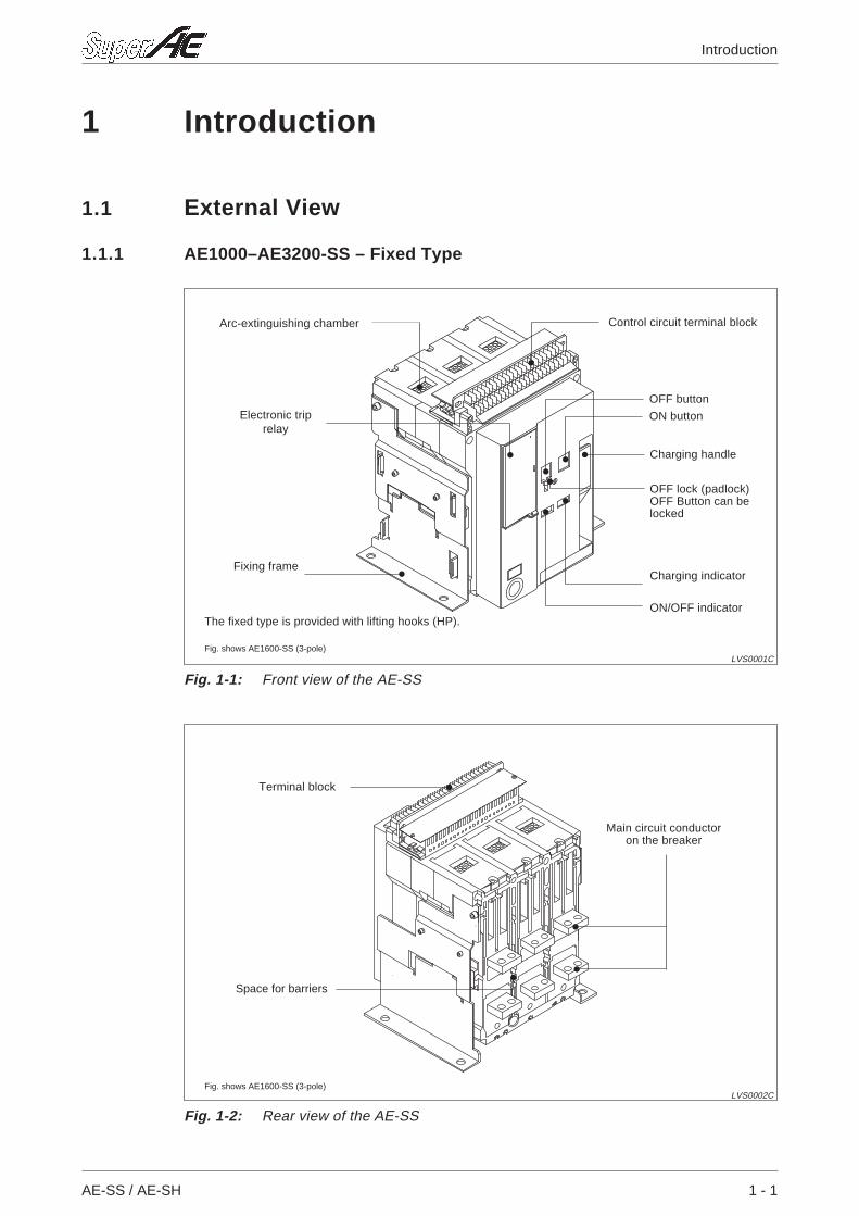
1 Introduction
1.1 External View
1.1.1 AE1000–AE3200-SS – Fixed Type
AE-SS / AE-SH 1 - 1
Introduction
Fig. 1-1: Front view of the AE-SS
LVS0001C
Arc-extinguishing chamber
Electronic triprelay
Control circuit terminal block
Fixing frame
ON button
OFF button
ON/OFF indicator
Charging indicator
Charging handle
OFF lock (padlock)OFF Button can belocked
Fig. shows AE1600-SS (3-pole)
The fixed type is provided with lifting hooks (HP).
Fig. 1-2: Rear view of the AE-SS
LVS0002C
Space for barriers
Main circuit conductoron the breaker
Terminal block
Fig. shows AE1600-SS (3-pole)
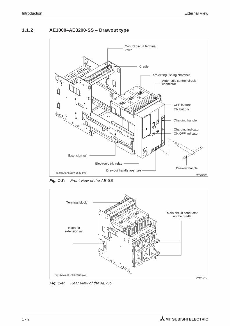
1.1.2 AE1000–AE3200-SS – Drawout type
1 - 2 MITSUBISHI ELECTRIC
Introduction External View
Fig. 1-3: Front view of the AE-SS
LVS0003C
Automatic control circuitconnector
Electronic trip relay
Control circuit terminalblock
Extension rail
ON buttonrOFF buttonr
ON/OFF indicatorCharging indicator
Charging handle
Cradle
Drawout handle aperture
Arc-extinguishing chamber
Fig. shows AE1600-SS (3-pole)
Fig. 1-4: Rear view of the AE-SS
LVS0004C
Main circuit conductoron the cradle
Terminal block
Insert forextension rail
Fig. shows AE1600-SS (3-pole)
Drawout handle
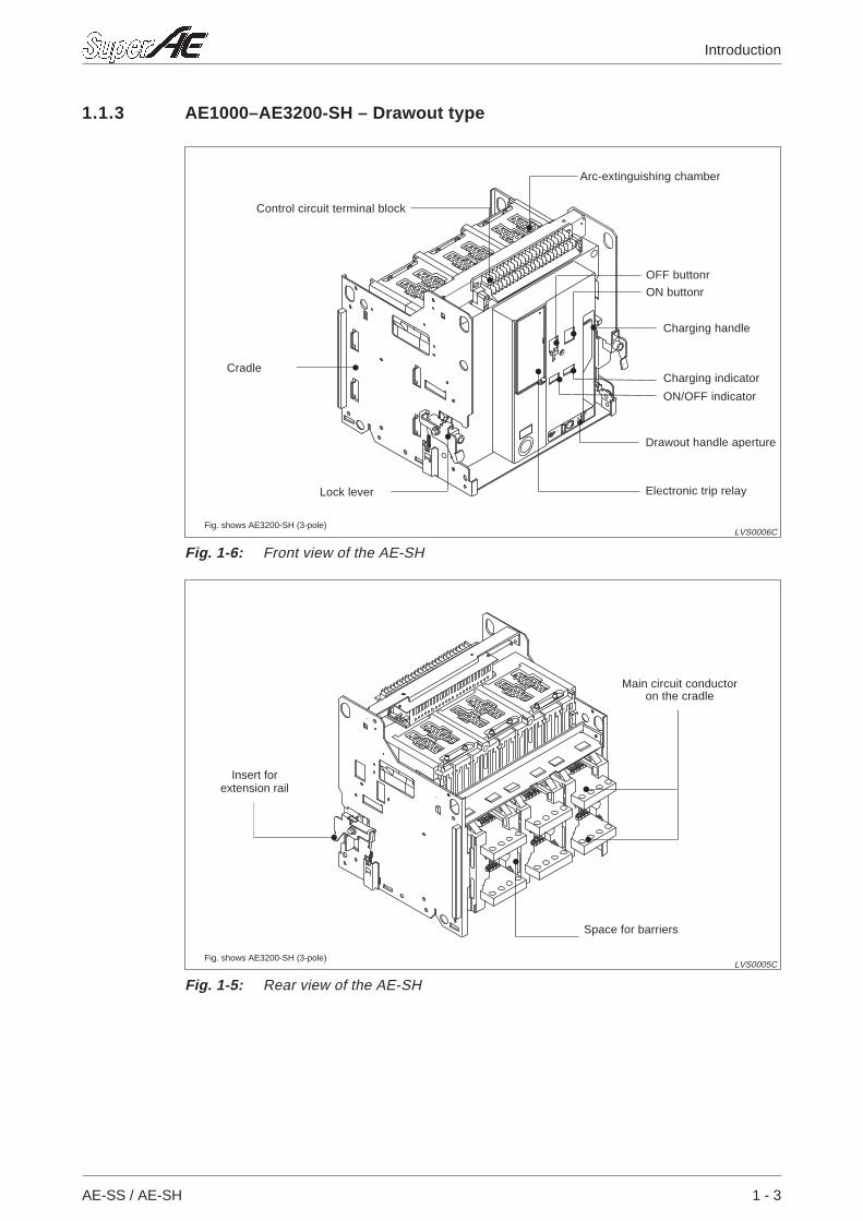
1.1.3 AE1000–AE3200-SH – Drawout type
AE-SS / AE-SH 1 - 3
Introduction
Space for barriers
Main circuit conductoron the cradle
Insert forextension rail
Fig. shows AE3200-SH (3-pole)
Fig. 1-5: Rear view of the AE-SH
LVS0005C
Electronic trip relay
ON buttonr
OFF buttonr
ON/OFF indicator
Charging indicator
Charging handle
Drawout handle aperture
Control circuit terminal block
Cradle
Lock lever
Arc-extinguishing chamber
Fig. shows AE3200-SH (3-pole)
Fig. 1-6: Front view of the AE-SH
LVS0006C
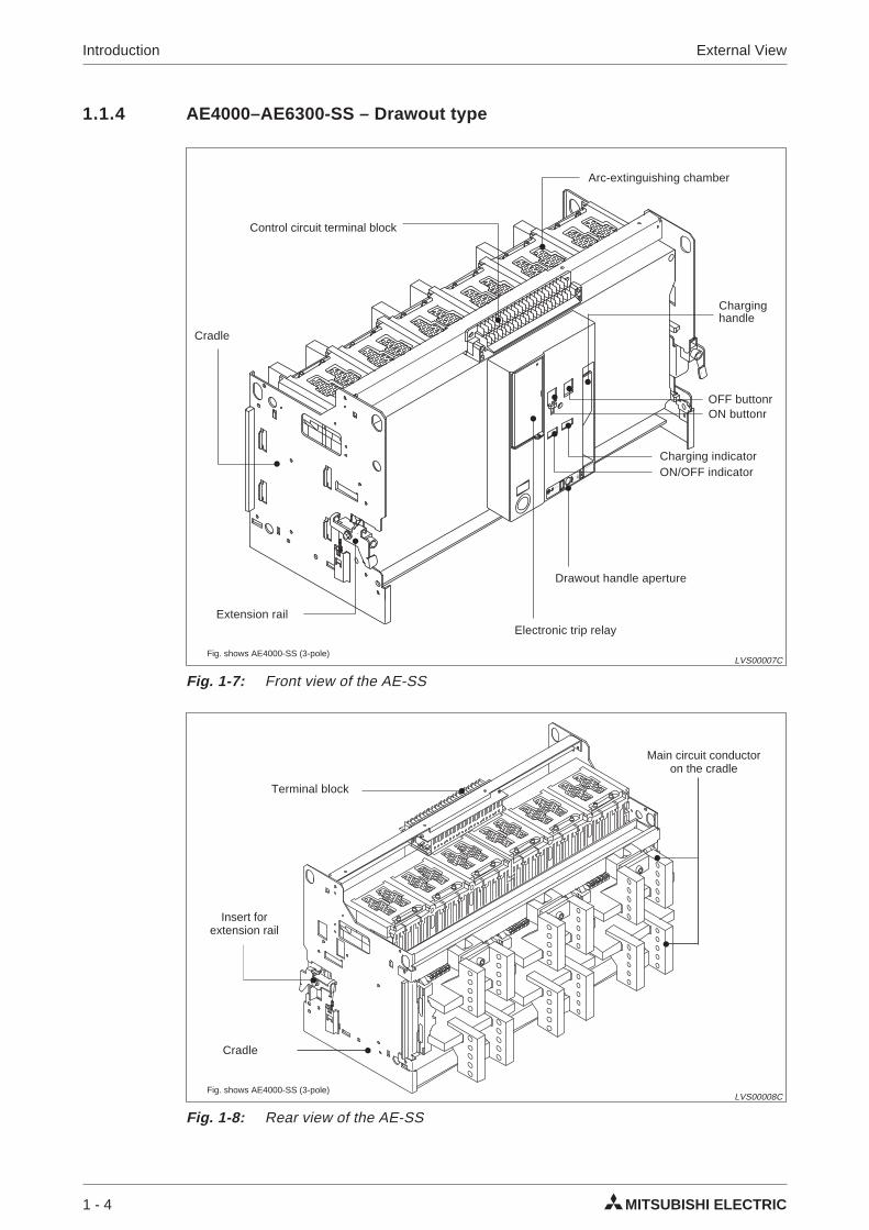
1.1.4 AE4000–AE6300-SS – Drawout type
1 - 4 MITSUBISHI ELECTRIC
Introduction External View
Fig. 1-7: Front view of the AE-SS
LVS00007C
Electronic trip relay
Control circuit terminal block
Extension rail
ON buttonrOFF buttonr
Charginghandle
Cradle
Drawout handle aperture
Arc-extinguishing chamber
Fig. shows AE4000-SS (3-pole)
ON/OFF indicatorCharging indicator
Fig. 1-8: Rear view of the AE-SS
LVS00008C
Cradle
Main circuit conductoron the cradle
Terminal block
Insert forextension rail
Fig. shows AE4000-SS (3-pole)
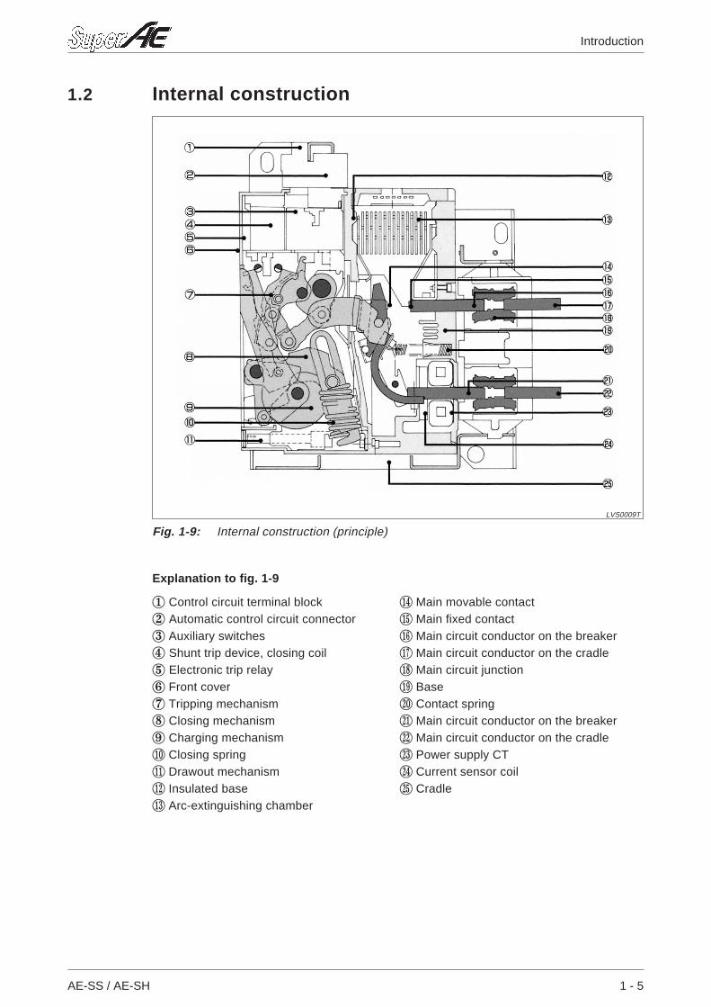
1.2 Internal construction
Explanation to fig. 1-9
AE-SS / AE-SH 1 - 5
Introduction
Fig. 1-9: Internal construction (principle)
LVS0009T
1 Control circuit terminal block AN Main movable contact
2 Automatic control circuit connector AO Main fixed contact
3 Auxiliary switches AP Main circuit conductor on the breaker
4 Shunt trip device, closing coil AQ Main circuit conductor on the cradle
5 Electronic trip relay AR Main circuit junction
6 Front cover AS Base
7 Tripping mechanism BT Contact spring
8 Closing mechanism BK Main circuit conductor on the breaker
9 Charging mechanism BL Main circuit conductor on the cradle
AT Closing spring BM Power supply CT
AK Drawout mechanism BN Current sensor coil
AL Insulated base BO Cradle
AM Arc-extinguishing chamber
1 - 6 MITSUBISHI ELECTRIC
Introduction Internal construction
2 Set-up
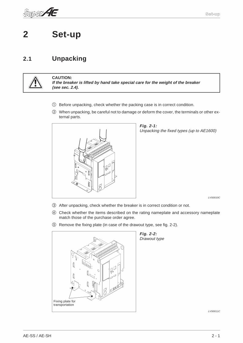
2.1 Unpacking
ECAUTION:If the breaker is lifted by hand take special care for the weight of the breaker(see sec. 2.4).
Before unpacking, check whether the packing case is in correct condition.
When unpacking, be careful not to damage or deform the cover, the terminals or other ex-ternal parts.
After unpacking, check whether the breaker is in correct condition or not.
Check whether the items described on the rating nameplate and accessory nameplatematch those of the purchase order agree.
Remove the fixing plate (in case of the drawout type, see fig. 2-2).
AE-SS / AE-SH 2 - 1
Set-up
Fig. 2-1:Unpacking the fixed types (up to AE1600)
LVS0010C
CONNECTED
LOCK
RELEASE
CONNECTEDTEST
DISCONNECTED
DISCONNECTED
Only For
Locked
Position
Fig. 2-2:Drawout type
LVS0011C
Fixing plate fortransportation
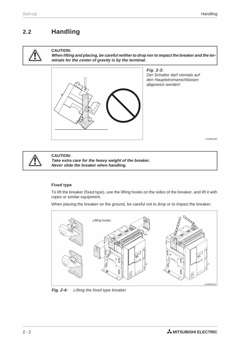
2.2 Handling
ECAUTION:When lifting and placing, be careful neither to drop nor to impact the breaker and the ter-minals for the center of gravity is by the terminal.
ECAUTION:Take extra care for the heavy weight of the breaker.Never slide the breaker when handling.
Fixed type
To lift the breaker (fixed type), use the lifting hooks on the sides of the breaker, and lift it withropes or similar equipment.
When placing the breaker on the ground, be careful not to drop or to impact the breaker.
2 - 2 MITSUBISHI ELECTRIC
Set-up Handling
Fig. 2-3:Der Schalter darf niemals aufden Hauptstromanschlüssenabgesetzt werden!
LVS0A13C
Fig. 2-4: Lifting the fixed type breaker
LVS0012C
Lifting hooks
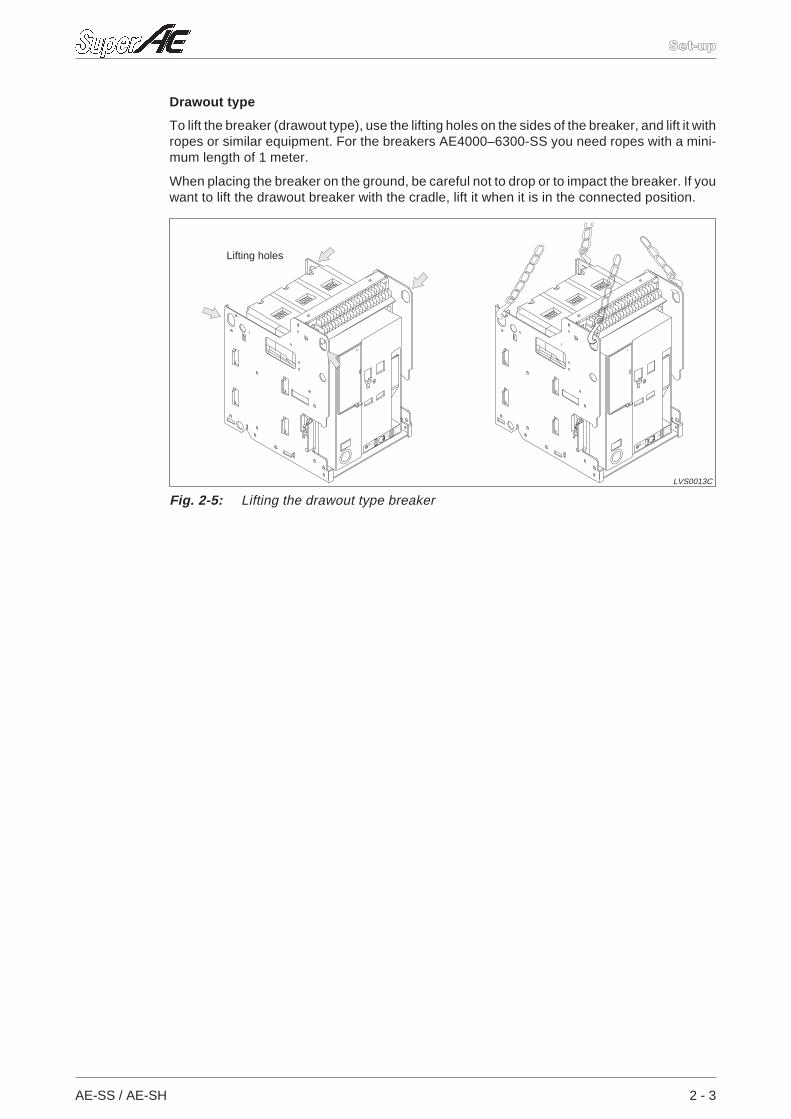
Drawout type
To lift the breaker (drawout type), use the lifting holes on the sides of the breaker, and lift it withropes or similar equipment. For the breakers AE4000–6300-SS you need ropes with a mini-mum length of 1 meter.
When placing the breaker on the ground, be careful not to drop or to impact the breaker. If youwant to lift the drawout breaker with the cradle, lift it when it is in the connected position.
AE-SS / AE-SH 2 - 3
Set-up
CONNECTED
LOCK
RELEASE
CONNECTEDTEST
DISCONNECTED
DISCONNECTED
Only For
Locked
Position
CONNECTED
LOCK
RELEASE
CONNECTEDTEST
DISCONNECTED
DISCONNECTED
Only For
Locked
Position
Fig. 2-5: Lifting the drawout type breaker
LVS0013C
Lifting holes
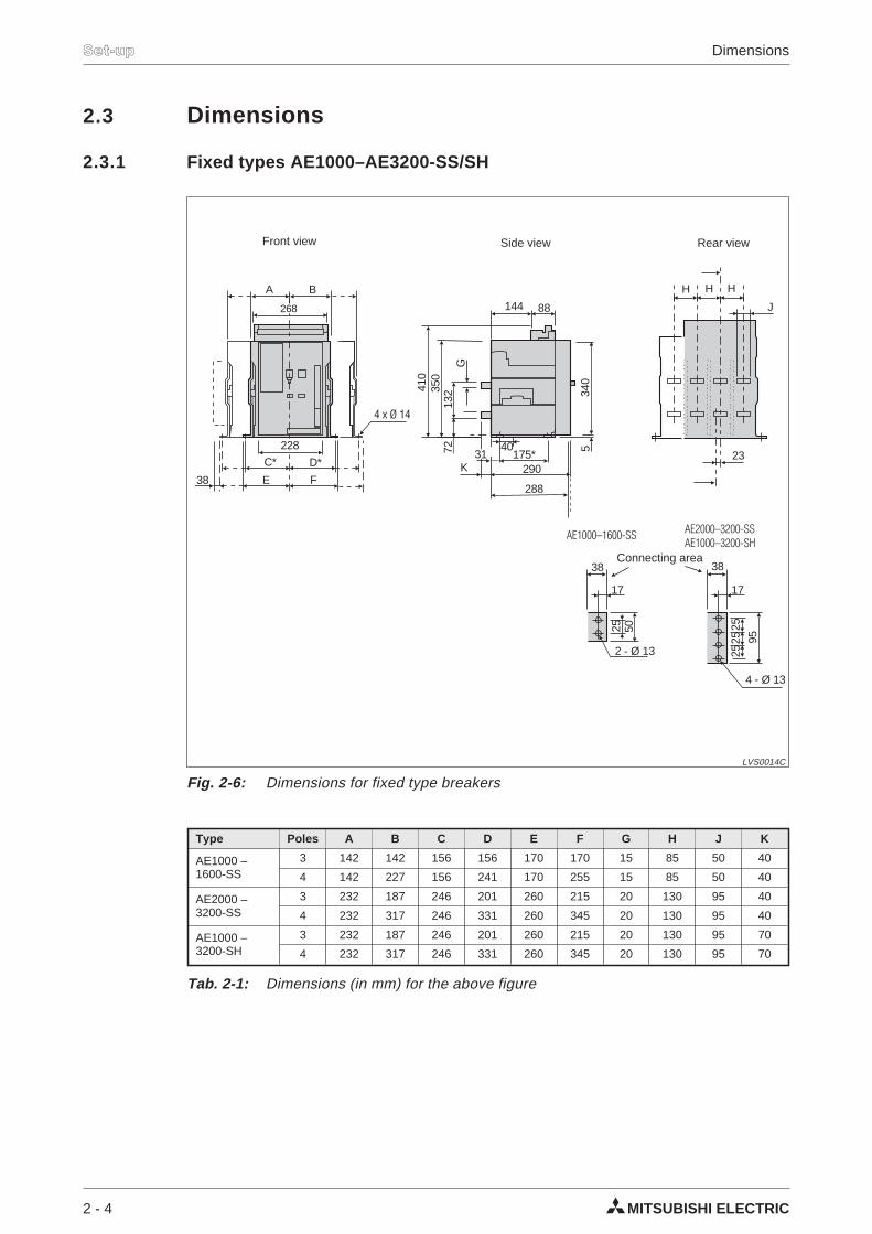
2.3 Dimensions
2.3.1 Fixed types AE1000–AE3200-SS/SH
2 - 4 MITSUBISHI ELECTRIC
Set-up Dimensions
Type Poles A B C D E F G H J K
AE1000 –1600-SS
3 142 142 156 156 170 170 15 85 50 40
4 142 227 156 241 170 255 15 85 50 40
AE2000 –3200-SS
3 232 187 246 201 260 215 20 130 95 40
4 232 317 246 331 260 345 20 130 95 40
AE1000 –3200-SH
3 232 187 246 201 260 215 20 130 95 70
4 232 317 246 331 260 345 20 130 95 70
Tab. 2-1: Dimensions (in mm) for the above figure
175*
88144
290
340
540
288
G72
350
410
132
C*
A B H H H
J
23D*
E38 F
4 x Ø 14
268
228
4 - Ø 13
K
17
38
25
9525252 - Ø 13
5025
17
38
31
AE1000–1600-SS AE2000–3200-SSAE1000–3200-SH
Fig. 2-6: Dimensions for fixed type breakers
LVS0014C
Front view Side view
Connecting area
Rear view
2.3.2 Drawout types AE1000–AE3200-SS
AE-SS / AE-SH 2 - 5
Set-up
A B
C59
42,5
40
D
K
L
K K
4 - Ø 13
15
38
25
103
25252 - Ø 13
5025
15
38
228
200*23
E
JJ
F
G
H
452
220*
40
23 48
25
61
3551
13237
0 430
340
15
AE1000–1600-SS AE2000–3200-SS
92
Ø 22
Ø12
200
200
169
max.173
Fig. 2-7: Dimensions for drawout type breakers
LVS0015C
Connecting area
Rear viewSide viewFront view
Drawout handle
Type Poles A B C D E F G H J K L
AE1000 –1600-SS
3 150 150 149 149 311 368 366 172 15 85 50
4 150 235 149 234 311 368 366 172 15 85 50
AE2000 –3200-SS
3 240 195 239 194 311 368 366 172 25 130 103
4 240 325 239 324 311 368 366 172 25 130 103
Tab. 2-2: Dimensions (in mm) for the above figure
2.3.3 Drawout types AE1000–AE3200-SH
2 - 6 MITSUBISHI ELECTRIC
Set-up Dimensions
243 3P: 1954P: 325
26533
42,5
4013
4
3P: 2204P: 350
130
B
4P 3P
130 130
4 - Ø 13
15
38
25B25
25
228
200*
23
341
AA
398396
202
452220*
4023 48
25
61
3551
13237
0 430
340
15
92
Ø 22
Ø12
200
200
169
max.173
Fig. 2-8: Dimensions for drawout type breakers
LVS1015C
Front view Side view Rear view
Drawout handle
Connecting area
2.3.4 Fixed types AE4000–SSA
AE-SS / AE-SH 2 - 7
Set-up
232 4P: 317 (3P:187)
268
3P 4P
38 260
246*
228
4P: 345 (3P: 215)
4P: 331* (3P: 201*)
144 88
152 152
23
95
31
145 145 145
30,5
95
31
1111
40
7
31
129,
5
175*
136 290
288
67
35041
0
340
5
10 10
182
125
57
Fig. 2-9: Dimensions for drawout type breakers
LVS1016C
Front view
Rear view 3-poles Rear view 4-poles
Side view
2.3.5 Drawout types AE4000–SSA
2 - 8 MITSUBISHI ELECTRIC
Set-up Dimensions
243
2283P 4P
42,5
200*
2395940
340
430
4P: 324 (3P: 194)
4P: 325 (3P: 195) 51
4823
2540172
220*
368
366
109 452
35
15
15
370
125
125
311
190
197 242
23
5210
11
190
67
170
327 242
5210
11
170 170
4318
2
Fig. 2-10: Dimensions for drawout type breakers
LVS1017C
Front view
Side view
Rear view 4-polesRear view 3-poles
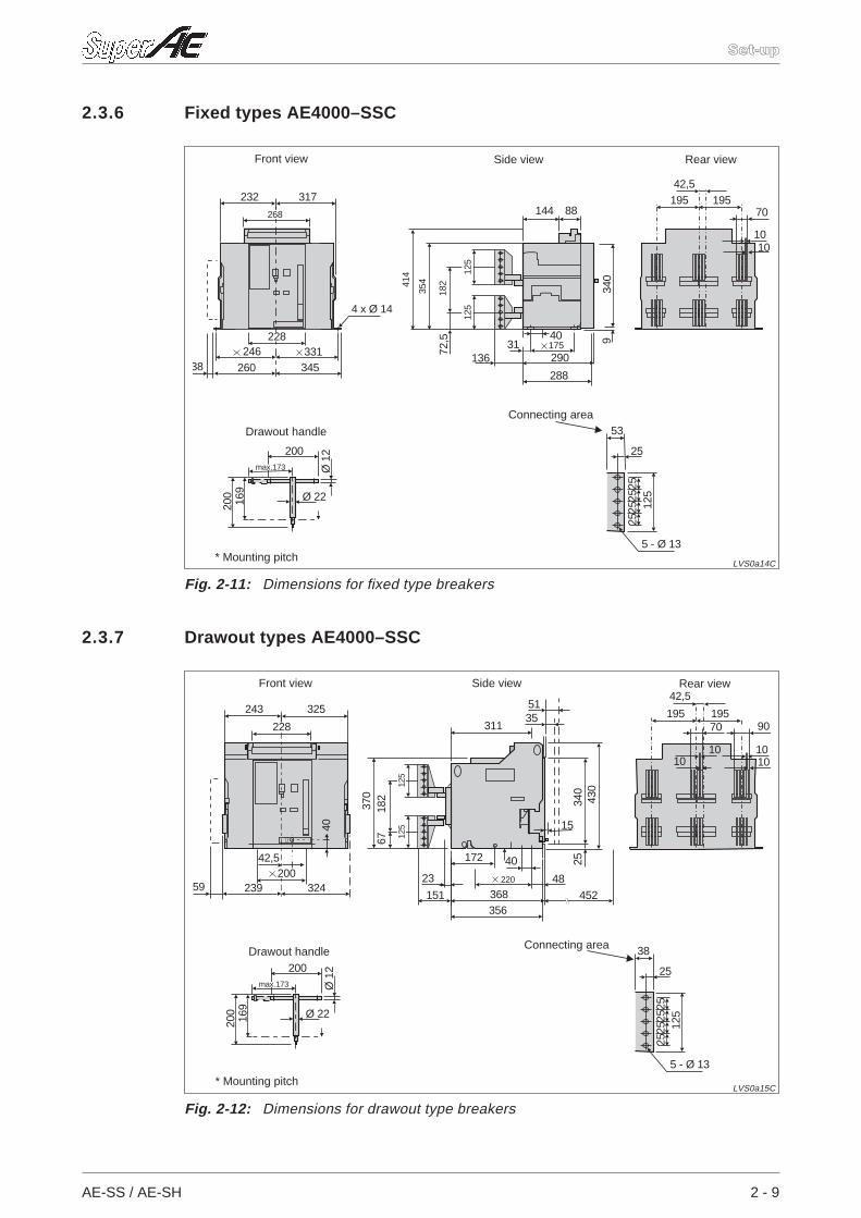
2.3.6 Fixed types AE4000–SSC
2.3.7 Drawout types AE4000–SSC
AE-SS / AE-SH 2 - 9
Set-up
232 317
26038 345
4 x Ø 14
268
228246 331
88144
290
340
9
72,5 40
288
13631 175
125
182
35441
4
125
10
42,5
10
70195 195
5 - Ø 13
25
53
2512
52525
25
Ø 22
Ø12
200
200
169
max.173
Fig. 2-11: Dimensions for fixed type breakers
LVS0a14C
Connecting area
Rear viewFront view
Drawout handle
* Mounting pitch
Side view
243 325
23959
42,5
40
324
228
200
311
368356
172
452
40
23 48
25
151
3551
182
370
67
430
340
15
220
125
125
1010
42,5
1010
9070195 195
Ø 22
Ø12
200
200
169
max.173
5 - Ø 13
25
38
2512
52525
25
Fig. 2-12: Dimensions for drawout type breakers
LVS0a15C
Connecting area
Rear viewSide viewFront view
Drawout handle
* Mounting pitch
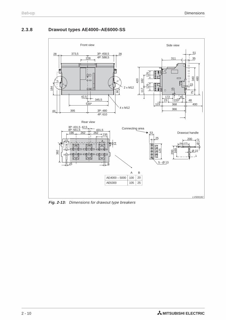
2.3.8 Drawout types AE4000–AE6000-SS
2 - 10 MITSUBISHI ELECTRIC
Set-up Dimensions
431,542,5
196 262 262235
4P: 561,53P: 431,5
382
14
25 B
103 A
373,5 3P: 458,54P: 588,5
3P: 4804P: 610
44
28 28
42,5
90
345,5
4 x M12
2 x M12
395
184
530*
228 311
366
172220*
368
4023 48
123
35
51
182
117
420
125
125
480
340
75
400
15
15
AE4000 – 5000 100 20
25AE6300 105
A B
Ø 22
Ø12
200
200
169
max.173
5 - Ø 13
25
53
2512
52525
25
Fig. 2-13: Dimensions for drawout type breakers
LVS0016C
Connecting area
Rear view
Side viewFront view
Drawout handle
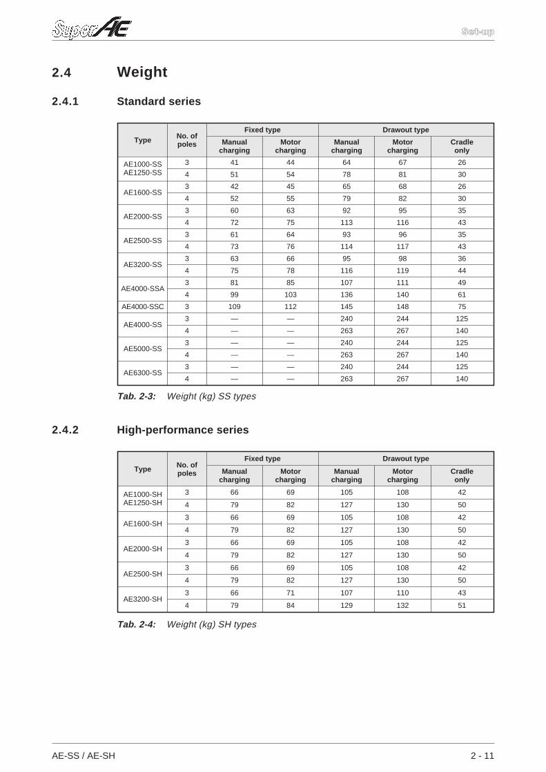
2.4 Weight
2.4.1 Standard series
2.4.2 High-performance series
AE-SS / AE-SH 2 - 11
Set-up
Type No. ofpoles
Fixed type Drawout type
Manualcharging
Motorcharging
Manualcharging
Motorcharging
Cradleonly
AE1000-SSAE1250-SS
3 41 44 64 67 26
4 51 54 78 81 30
AE1600-SS3 42 45 65 68 26
4 52 55 79 82 30
AE2000-SS3 60 63 92 95 35
4 72 75 113 116 43
AE2500-SS3 61 64 93 96 35
4 73 76 114 117 43
AE3200-SS3 63 66 95 98 36
4 75 78 116 119 44
AE4000-SSA3 81 85 107 111 49
4 99 103 136 140 61
AE4000-SSC 3 109 112 145 148 75
AE4000-SS3 — — 240 244 125
4 — — 263 267 140
AE5000-SS3 — — 240 244 125
4 — — 263 267 140
AE6300-SS3 — — 240 244 125
4 — — 263 267 140
Tab. 2-3: Weight (kg) SS types
Type No. ofpoles
Fixed type Drawout type
Manualcharging
Motorcharging
Manualcharging
Motorcharging
Cradleonly
AE1000-SHAE1250-SH
3 66 69 105 108 42
4 79 82 127 130 50
AE1600-SH3 66 69 105 108 42
4 79 82 127 130 50
AE2000-SH3 66 69 105 108 42
4 79 82 127 130 50
AE2500-SH3 66 69 105 108 42
4 79 82 127 130 50
AE3200-SH3 66 71 107 110 43
4 79 84 129 132 51
Tab. 2-4: Weight (kg) SH types
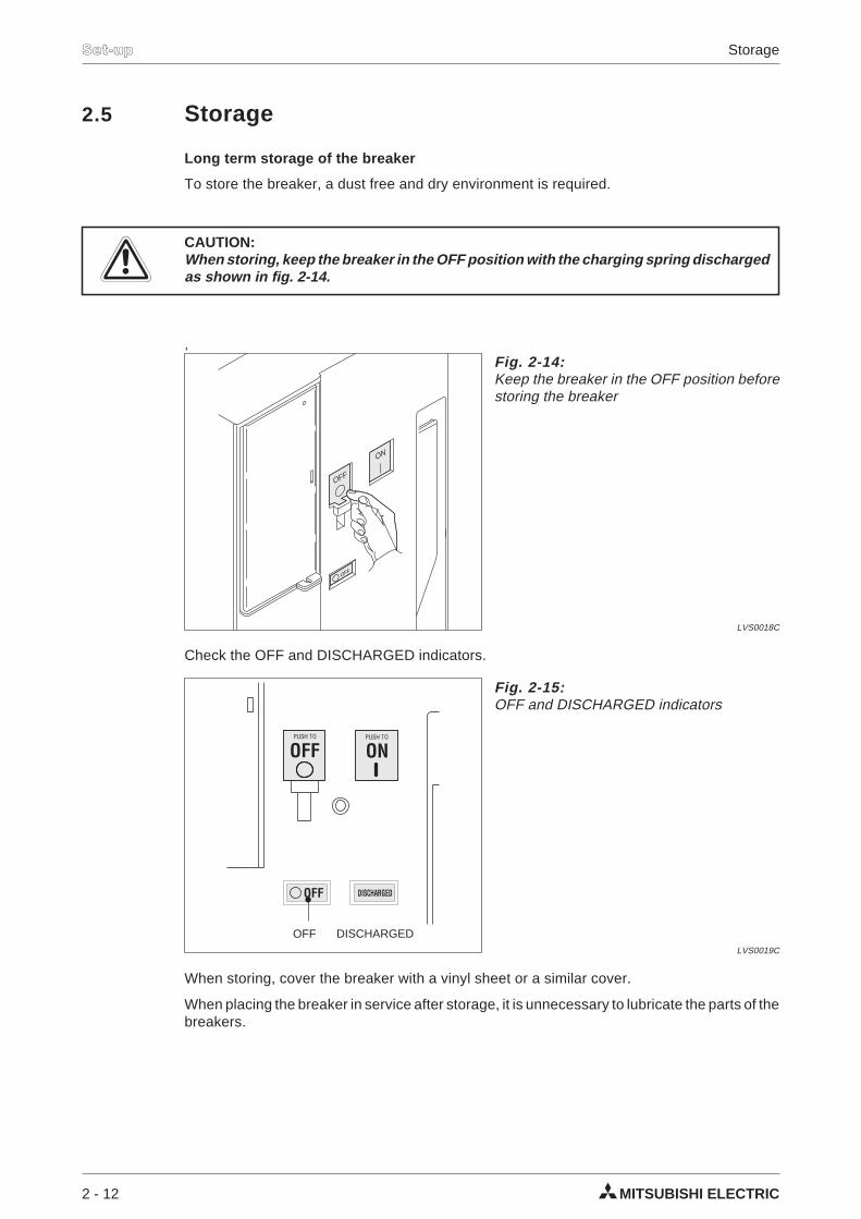
2.5 Storage
Long term storage of the breaker
To store the breaker, a dust free and dry environment is required.
ECAUTION:When storing, keep the breaker in the OFF position with the charging spring dischargedas shown in fig. 2-14.
,
Check the OFF and DISCHARGED indicators.
When storing, cover the breaker with a vinyl sheet or a similar cover.
When placing the breaker in service after storage, it is unnecessary to lubricate the parts of thebreakers.
2 - 12 MITSUBISHI ELECTRIC
Set-up Storage
OFF
OFF
ON
Fig. 2-14:Keep the breaker in the OFF position beforestoring the breaker
LVS0018C
OFF DISCHARGED
OFFPUSH TO
ONPUSH TO
Fig. 2-15:OFF and DISCHARGED indicators
LVS0019C
OFF DISCHARGED
2.6 Installation
2.6.1 Fixed types
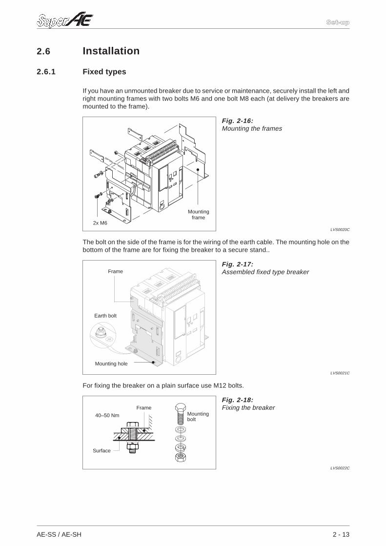
If you have an unmounted breaker due to service or maintenance, securely install the left andright mounting frames with two bolts M6 and one bolt M8 each (at delivery the breakers aremounted to the frame).
The bolt on the side of the frame is for the wiring of the earth cable. The mounting hole on thebottom of the frame are for fixing the breaker to a secure stand..
For fixing the breaker on a plain surface use M12 bolts.
AE-SS / AE-SH 2 - 13
Set-up
Fig. 2-16:Mounting the frames
LVS0020C
2x M6
Mountingframe
Fig. 2-17:Assembled fixed type breaker
LVS0021C
Mounting hole
Earth bolt
Frame
Fig. 2-18:Fixing the breaker
LVS0022C
Mountingbolt
Surface
Frame
40–50 Nm
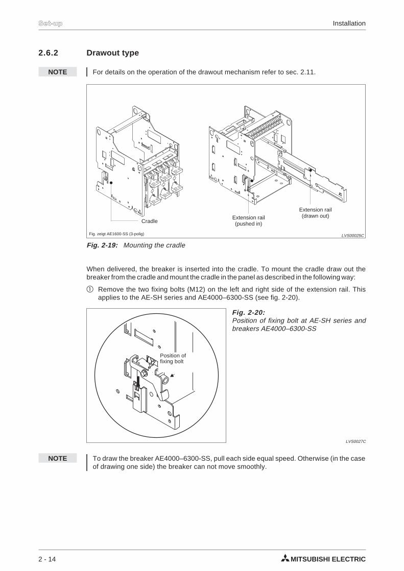
2.6.2 Drawout type
NOTE For details on the operation of the drawout mechanism refer to sec. 2.11.
When delivered, the breaker is inserted into the cradle. To mount the cradle draw out thebreaker from the cradle and mount the cradle in the panel as described in the following way:
Remove the two fixing bolts (M12) on the left and right side of the extension rail. Thisapplies to the AE-SH series and AE4000–6300-SS (see fig. 2-20).
NOTE To draw the breaker AE4000–6300-SS, pull each side equal speed. Otherwise (in the caseof drawing one side) the breaker can not move smoothly.
2 - 14 MITSUBISHI ELECTRIC
Set-up Installation
Fig. 2-19: Mounting the cradle
LVS00025C
Extension rail(pushed in) Cradle
Fig. zeigt AE1600-SS (3-polig)
Extension rail(drawn out)
Fig. 2-20:Position of fixing bolt at AE-SH series andbreakers AE4000–6300-SS
LVS0027C
Position offixing bolt
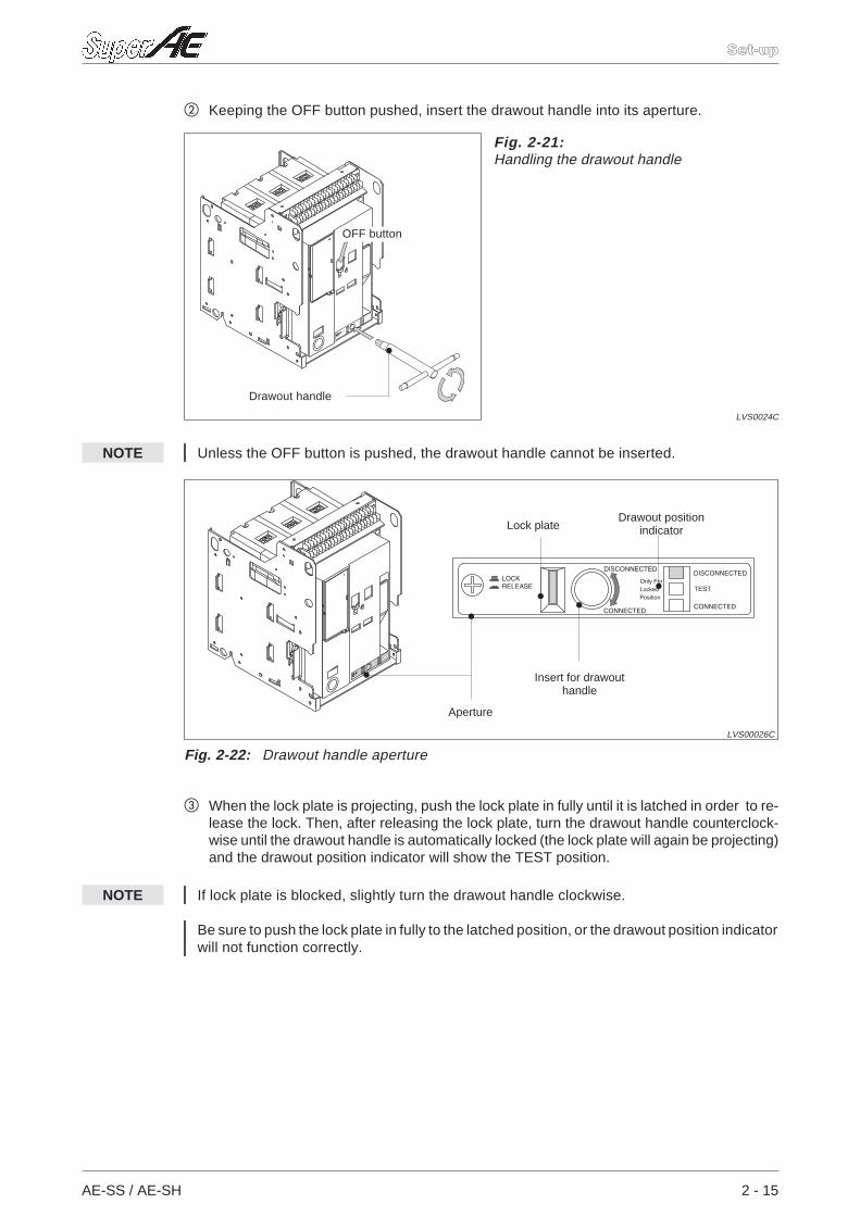
Keeping the OFF button pushed, insert the drawout handle into its aperture.
NOTE Unless the OFF button is pushed, the drawout handle cannot be inserted.
When the lock plate is projecting, push the lock plate in fully until it is latched in order to re-lease the lock. Then, after releasing the lock plate, turn the drawout handle counterclock-wise until the drawout handle is automatically locked (the lock plate will again be projecting)and the drawout position indicator will show the TEST position.
NOTE If lock plate is blocked, slightly turn the drawout handle clockwise.
Be sure to push the lock plate in fully to the latched position, or the drawout position indicatorwill not function correctly.
AE-SS / AE-SH 2 - 15
Set-up
Fig. 2-21:Handling the drawout handle
LVS0024C
Drawout handle
OFF button
Fig. 2-22: Drawout handle aperture
LVS00026C
Drawout positionindicator
Insert for drawouthandle
Lock plate
Aperture
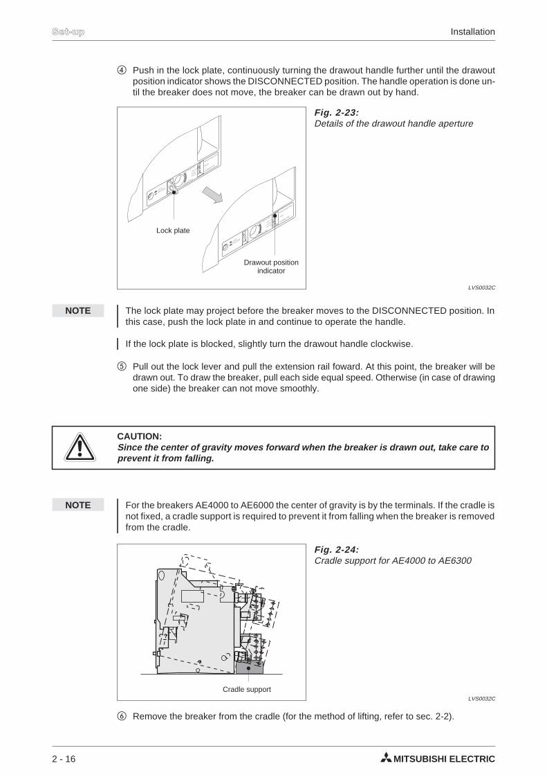
Push in the lock plate, continuously turning the drawout handle further until the drawoutposition indicator shows the DISCONNECTED position. The handle operation is done un-til the breaker does not move, the breaker can be drawn out by hand.
NOTE The lock plate may project before the breaker moves to the DISCONNECTED position. Inthis case, push the lock plate in and continue to operate the handle.
If the lock plate is blocked, slightly turn the drawout handle clockwise.
Pull out the lock lever and pull the extension rail foward. At this point, the breaker will bedrawn out. To draw the breaker, pull each side equal speed. Otherwise (in case of drawingone side) the breaker can not move smoothly.
ECAUTION:Since the center of gravity moves forward when the breaker is drawn out, take care toprevent it from falling.
NOTE For the breakers AE4000 to AE6000 the center of gravity is by the terminals. If the cradle isnot fixed, a cradle support is required to prevent it from falling when the breaker is removedfrom the cradle.
Remove the breaker from the cradle (for the method of lifting, refer to sec. 2-2).
2 - 16 MITSUBISHI ELECTRIC
Set-up Installation
Fig. 2-23:Details of the drawout handle aperture
LVS0032C
Drawout positionindicator
Lock plate
Fig. 2-24:Cradle support for AE4000 to AE6300
LVS0032C
Cradle support
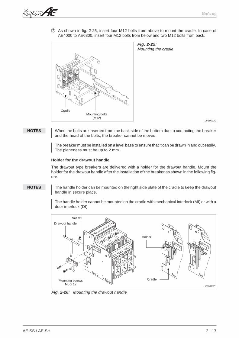
As shown in fig. 2-25, insert four M12 bolts from above to mount the cradle. In case ofAE4000 to AE6300, insert four M12 bolts from below and two M12 bolts from back.
NOTES When the bolts are inserted from the back side of the bottom due to contacting the breakerand the head of the bolts, the breaker cannot be moved.
The breaker must be installed on a level base to ensure that it can be drawn in and out easily.The planeness must be up to 2 mm.
Holder for the drawout handle
The drawout type breakers are delivered with a holder for the drawout handle. Mount theholder for the drawout handle after the installation of the breaker as shown in the following fig-ure.
NOTES The handle holder can be mounted on the right side plate of the cradle to keep the drawouthandle in secure place.
The handle holder cannot be mounted on the cradle with mechanical interlock (MI) or with adoor interlock (DI).
AE-SS / AE-SH 2 - 17
Set-up
Fig. 2-25:Mounting the cradle
LVS0032C
Mounting bolts(M12)
Cradle
Fig. 2-26: Mounting the drawout handle
LVS0023C
Cradle
Drawout handle
Mounting screwsM5 x 12
Nut M5
Holder
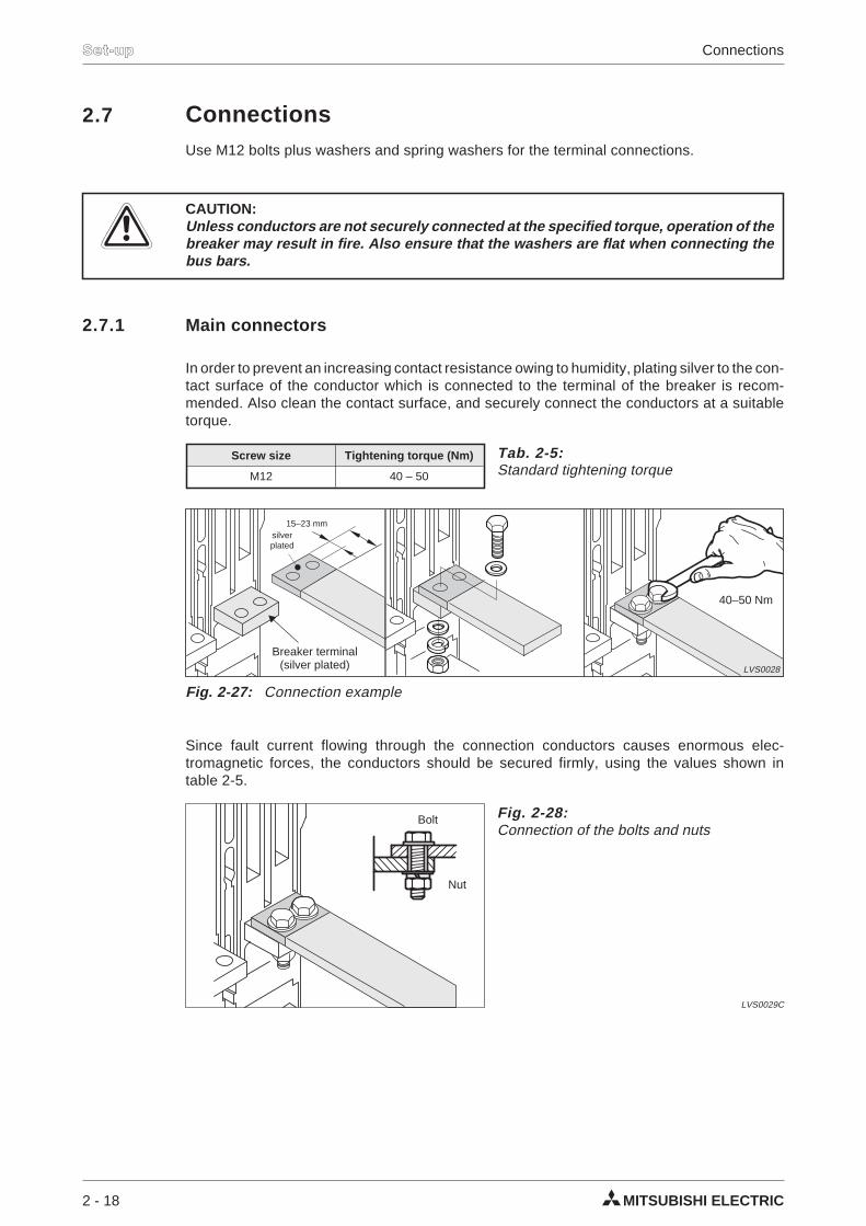
2.7 ConnectionsUse M12 bolts plus washers and spring washers for the terminal connections.
ECAUTION:Unless conductors are not securely connected at the specified torque, operation of thebreaker may result in fire. Also ensure that the washers are flat when connecting thebus bars.
2.7.1 Main connectors
In order to prevent an increasing contact resistance owing to humidity, plating silver to the con-tact surface of the conductor which is connected to the terminal of the breaker is recom-mended. Also clean the contact surface, and securely connect the conductors at a suitabletorque.
Since fault current flowing through the connection conductors causes enormous elec-tromagnetic forces, the conductors should be secured firmly, using the values shown intable 2-5.
2 - 18 MITSUBISHI ELECTRIC
Set-up Connections
Screw size Tightening torque (Nm)
M12 40 – 50
Tab. 2-5:Standard tightening torque
Fig. 2-27: Connection example
LVS0028
Breaker terminal(silver plated)
40–50 Nm
15–23 mmsilverplated
Fig. 2-28:Connection of the bolts and nuts
LVS0029C
Nut
Bolt
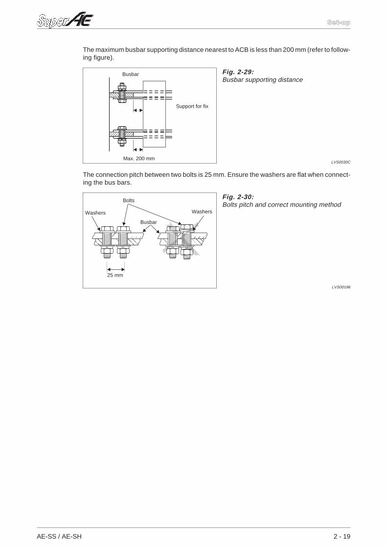
The maximum busbar supporting distance nearest to ACB is less than 200 mm (refer to follow-ing figure).
The connection pitch between two bolts is 25 mm. Ensure the washers are flat when connect-ing the bus bars.
AE-SS / AE-SH 2 - 19
Set-up
Fig. 2-29:Busbar supporting distance
LVS0030C
Busbar
Support for fix
Max. 200 mm
Fig. 2-30:Bolts pitch and correct mounting method
LVS00196
Busbar
WashersWashers
Bolts
25 mm
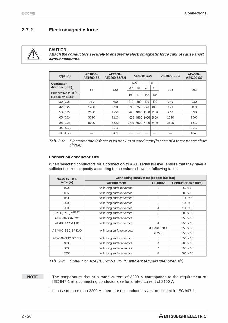
2.7.2 Electromagnetic force
ECAUTION:Attach the conductors securely to ensure the electromagnetic force cannot cause shortcircuit accidents.
Connection conductor size
When selecting conductors for a connection to a AE series breaker, ensure that they have asufficient current capacity according to the values shown in following table.
NOTE The temperature rise at a rated current of 3200 A corresponds to the requirement ofIEC 947-1 at a connecting conductor size for a rated current of 3150 A.
In case of more than 3200 A, there are no conductor sizes prescribed in IEC 947-1.
2 - 20 MITSUBISHI ELECTRIC
Set-up Connections
Type (A) AE1000–AE1600-SS
AE2000–AE3200-SS/SH AE4000-SSA AE4000-SSC AE4000–
AE6300-SS
Conductordistance (mm)
85 130
D/O Fix
195 2623P 4P 3P 4P
Prospective faultcurrent kA (cosϕ) 190 170 152 145
30 (0.2) 750 450 340 380 420 420 340 230
42 (0.2) 1460 890 690 750 840 840 670 450
50 (0.2) 2080 1250 960 1060 1180 1180 940 630
65 (0.2) 3510 2120 1630 1800 2000 2000 1590 1060
85 (0.2) 6020 3620 2790 3070 3400 3400 2720 1810
100 (0.2) — 5010 — — — — — 2510
130 (0.2) — 8470 — — — — — 4240
Tab. 2-6: Electromagnetic force in kg per 1 m of conductor (in case of a three phase shortcircuit)
Rated currentmax. (A)
Connecting conductors (copper bus bar)
Arrangement Quantity Conductor size (mm)
1000 with long surface vertical 2 60 x 5
1250 with long surface vertical 2 80 x 5
1600 with long surface vertical 2 100 x 5
2000 with long surface vertical 3 100 x 5
2500 with long surface vertical 4 100 x 5
3150 (3200) *(NOTE) with long surface vertical 3 100 x 10
AE4000-SSA D/O with long surface vertical 3 150 x 10
AE4000-SSA FIX with long surface vertical 4 150 x 10
AE4000-SSC 3P D/O with long surface vertical(L1 and L3) 4 150 x 10
(L2) 3 150 x 10
AE4000-SSC 3P FIX with long surface vertical 3 150 x 10
4000 with long surface vertical 4 100 x 10
5000 with long surface vertical 4 150 x 10
6300 with long surface vertical 4 200 x 10
Tab. 2-7: Conductor size (IEC947-1; 40 °C ambient temperature; open air)
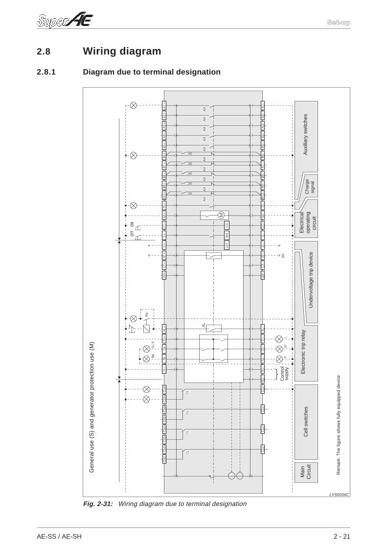
2.8 Wiring diagram
2.8.1 Diagram due to terminal designation
AE-SS / AE-SH 2 - 21
Set-up
TAL
Xa
G/ E
AL+
C
L
AXAX
AXAX
AXAX
AXAX
AXAX
AL
CL
CL
CL
AL–
T1–
R2–
R1–
T4–
T2– S/
IP
LSH
T
UVT
SHT
CC
SBC
SBC
SBC
SBC
SBC
M
CLc
CLc
CLc
CLb
CLa
CLb
CLa
CLb
CLa
CLb
CLa
LM+
CT+
S+C
C+
M+
TS+
B10+
B9+
B8+
B7+
B6+
A5+
A4+
A3+
A2+
A1+
U+ST
+
A4–
A5–
A3–
A2–
A1–
B6–
B7–
B8–
B9–
B10–
TS–
LM–
CT–
ST–
U–S–
CC
–M
–C
Lc
––
R+T5
T3T0
+
Fig. 2-31: Wiring diagram due to terminal designation
LVS0034C
Gen
eral
use
(S)
and
gene
rato
rpr
otec
tion
use
(M)
Rem
ark:
The
figur
esh
ows
fully
equi
pped
devi
ce
Mai
nC
ircui
tC
ells
witc
hes
Aux
iliar
ysw
itche
sE
lect
rical
oper
atin
gci
rcui
tU
nder
volta
getr
ipde
vice
OFF
ON
Con
trol
supp
ly
Ele
ctro
nic
trip
rela
yC
harg
esi
gnal
NOTES On the drawout type, the cables are cut to length, long enough to allow the control circuit ter-minal block to be moved to the left or right by 5 mm.
When a coil load is connected in the same control circuit of the OCR, surge absorbers are re-quired to absorb the surge voltage.
Mark description (terminals)
NOTE If the optional functions PAL, ER, TI, LM and TAL are attached, a control source is required.
ECAUTION:The control supply source should be free from distortion to prevent the breaker frommalfunction.
Mark description (accessories)
2 - 22 MITSUBISHI ELECTRIC
Set-up Wiring diagram
Auxiliary switch contact a For neutral pole CT or external ZCTconnection
Auxiliary switch contact b Load ammeter
Charge signal OCR alarm contact
Motor charging Trip indication contact
Closing coil Pre-alarm indication contact
Shunt trip Unusual temperature contact
Under voltage trip Electronic trip relay unitcontrol supply
Earth leakage trip output(for SHT trip) Cell switch
Tab. 2-8: Mark descriptions (terminals)
A1 A5
–B6 B10
TS
M
CC
S
U
ST
CT
LM
T0 T3
T4
T5
R1- R2-
CLa CLb CLc
–
–
AL
M Motor X G or E Ground fault trip or earth leakageindicator LED
Closing coil X P Pre-alarm indication LED
Shunt trip device X TAL Unusual temperature indicationLED
Undervoltage trip device Self-hold relay
AL OCR alarm Wiring completed by the factory
X L LTD trip indication LED Wiring to be done by the user
X S/I STD trip or INST trip indication LED
Tab. 2-9: Mark description (accessories)
CC
SHT
UVT
Voltage
100–120 V AC
200–240 V AC
24 ... 125 V DC
Tab. 2-10:Control supply terminals
R2-
R1-R+
R+
R1-R+
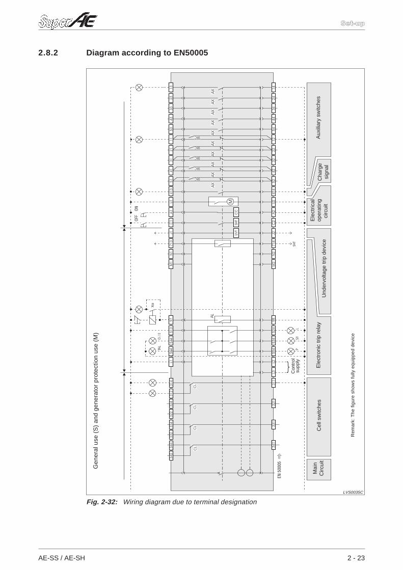
2.8.2 Diagram according to EN50005
AE-SS / AE-SH 2 - 23
Set-up
–TAL
Xa
G/ E
–
C
L
AXAX
AXAX
AXAX
AXAX
AXAX
AL
CL
CL
CL
S/I
PL
SHT
UVT
SHT
CC
SBC
SBC
SBC
SBC
SBC
M
9852
4L3
L255
453
4
97L1
EN50
005
341
331
321
M1
N1
C1
A1U1
413
5141
3121
1153
4333
2313
J171
3
4454
3424
1412
2232
4252
414
M2
N2
714
J2C
2A2
U2
564
544
513
311
342
344
332
334
322
324
312
314
Fig. 2-32: Wiring diagram due to terminal designation
LVS0035C
Ele
ctro
nic
trip
rela
y
Gen
eral
use
(S)
and
gene
rato
rpr
otec
tion
use
(M)
Rem
ark:
The
figur
esh
ows
fully
equi
pped
devi
ce
Mai
nC
ircui
tC
ells
witc
hes
Aux
iliar
ysw
itche
sU
nder
volta
getr
ipde
vice
OFF
ON
Con
trol
supp
ly
Cha
rge
sign
al
Ele
ctric
alop
erat
ing
circ
uit
NOTES On the drawout type, the cables are cut to length, long enough to allow the control circuit ter-minal block to be moved to the left or right by 5 mm.
When a coil load is connected in the same control circuit of the OCR, surge absorbers are re-quired to absorb the surge voltage.
Mark description (terminals)
NOTE If the optional functions PAL, ER, TI, LM and TAL are attached, a control source is required.
ECAUTION:The control supply source should be free from distortion to prevent the breaker frommalfunction.
Mark description (accessories)
2 - 24 MITSUBISHI ELECTRIC
Set-up Wiring diagram
Auxiliary switch contact a For neutral pole CT or external ZCTconnection
Auxiliary switch contact b Load ammeter
Charge signal OCR alarm contact
Motor charging Trip indication contact
Closing coil Pre-alarm indication contact
Shunt trip Unusual temperature contact
Under voltage trip Electronic trip relay unit controlsupply
Earth leakage trip output(for SHT trip) Cell switch
Tab. 2-11: Mark descriptions (terminals)
13 54
–11 52
413
U1
A1
C1
J1
713
524 544
554
564
L1 L2 L3
311 344
–
–
414
U2
A2
C2
J2
714
N1 N2
M1 M2
97 98
–
M Motor X G or E Ground fault trip or earth leakageindicator LED
Closing coil X P Pre-alarm indication LED
Shunt trip device X TAL Unusual temperature indicationLED
Undervoltage trip device Self-hold relay
AL OCR alarm Wiring completed by the factory
X L LTD trip indication LED Wiring to be done by the user
X S/I STD trip or INST trip indication LED
Tab. 2-12: Mark description (accessories)
CC
SHT
UVT
Voltage
100–120 V AC
200–240 V AC
24 ... 125 V DC
Tab. 2-13:Control supply terminals
L3
L2L1
L1
L2L1
2.9 Charging operation
2.9.1 Manual charging
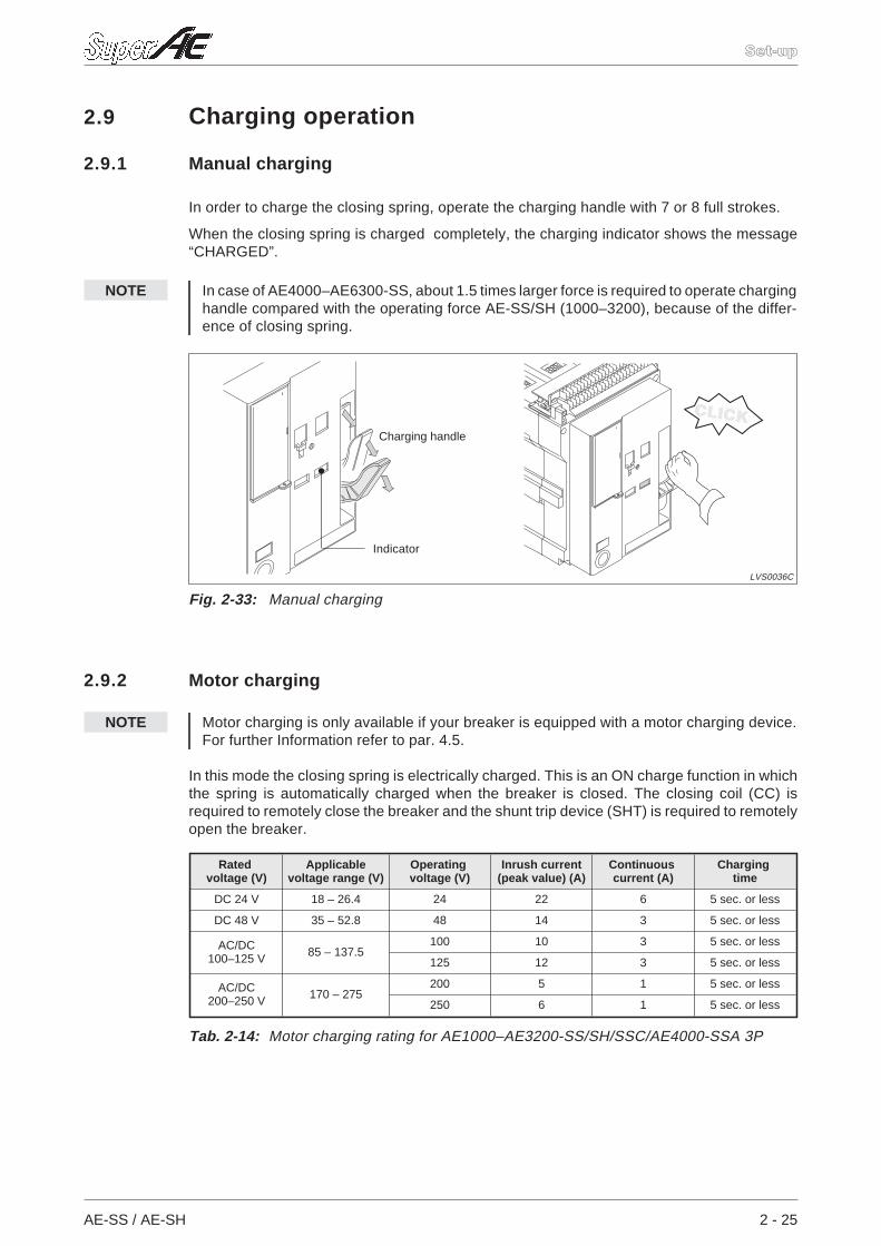
In order to charge the closing spring, operate the charging handle with 7 or 8 full strokes.
When the closing spring is charged completely, the charging indicator shows the message“CHARGED”.
NOTE In case of AE4000–AE6300-SS, about 1.5 times larger force is required to operate charginghandle compared with the operating force AE-SS/SH (1000–3200), because of the differ-ence of closing spring.
2.9.2 Motor charging
NOTE Motor charging is only available if your breaker is equipped with a motor charging device.For further Information refer to par. 4.5.
In this mode the closing spring is electrically charged. This is an ON charge function in whichthe spring is automatically charged when the breaker is closed. The closing coil (CC) isrequired to remotely close the breaker and the shunt trip device (SHT) is required to remotelyopen the breaker.
AE-SS / AE-SH 2 - 25
Set-up
CLICK
Fig. 2-33: Manual charging
LVS0036C
Charging handle
Indicator
Ratedvoltage (V)
Applicablevoltage range (V)
Operatingvoltage (V)
Inrush current(peak value) (A)
Continuouscurrent (A)
Chargingtime
DC 24 V 18 – 26.4 24 22 6 5 sec. or less
DC 48 V 35 – 52.8 48 14 3 5 sec. or less
AC/DC100–125 V 85 – 137.5
100 10 3 5 sec. or less
125 12 3 5 sec. or less
AC/DC200–250 V 170 – 275
200 5 1 5 sec. or less
250 6 1 5 sec. or less
Tab. 2-14: Motor charging rating for AE1000–AE3200-SS/SH/SSC/AE4000-SSA 3P
NOTES Manual charging operation is also possible with the charging handle.
Pumping prevention is assured both electrically and mechanically.
As long as the OFF button is pressed, a closing operation is impossible.
When the OFF lock device is used, perform the closing operation after the lock has been re-leased.
Although the charging motor has a short time rating it can be continuously operated for up toten times.
The opening and closing of the drawout type breaker must be carried out in either the con-nected or the test position.
If an under voltage trip device is fitted, its rated voltage should be applied before attemptingto close the breaker.
Since the charge complete contact is separate from the motor charging unit, the sequencecan be arranged as required.
2 - 26 MITSUBISHI ELECTRIC
Set-up Charging operation
Ratedvoltage (V)
Applicablevoltage range (V)
Operatingvoltage (V)
Inrush current(peak value) (A)
Continuouscurrent (A)
Chargingtime
AC/DC100–125 V 85 – 137.5
100 10 4 5 sec. or less
125 12 4 5 sec. or less
AC/DC200–2250 V 170 – 275
200 7 2 5 sec. or less
250 8 2 5 sec. or less
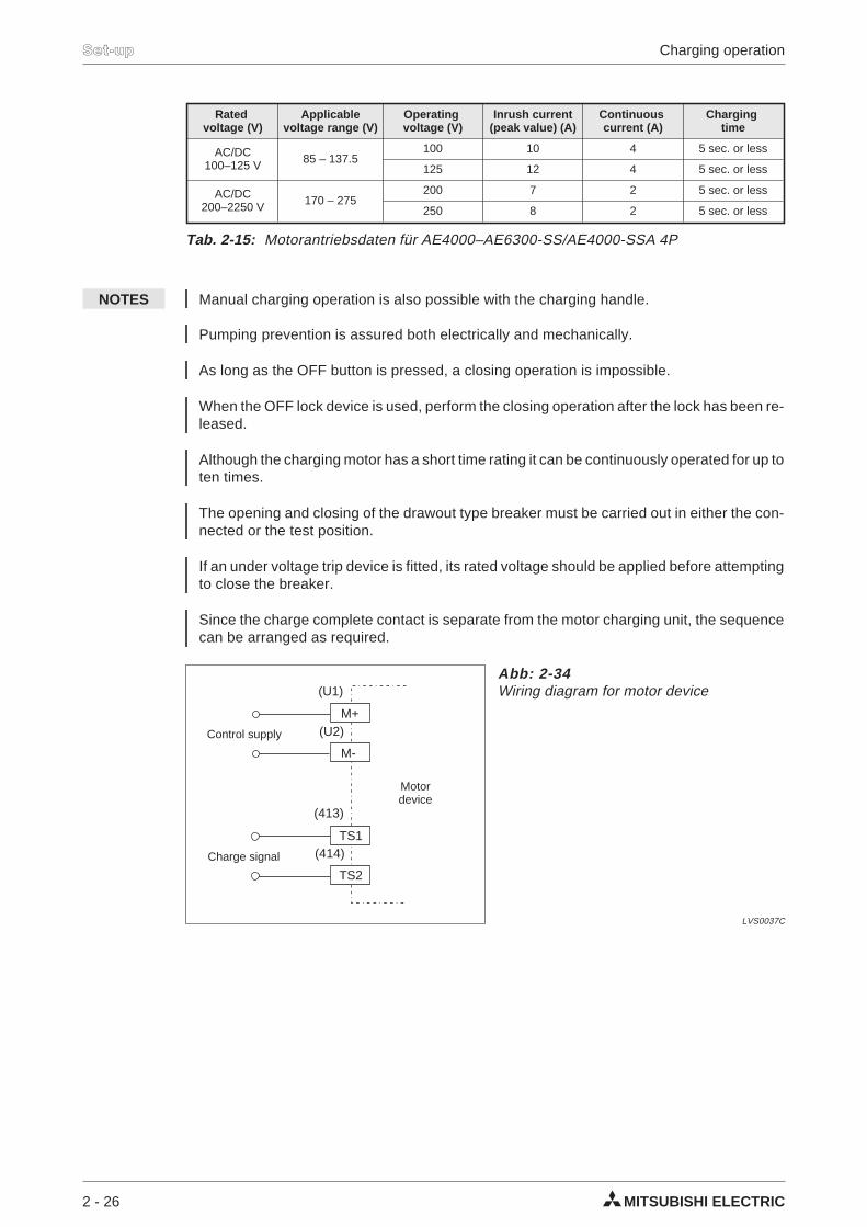
Tab. 2-15: Motorantriebsdaten für AE4000–AE6300-SS/AE4000-SSA 4P
TS1
TS2
(U1)
(413)
(U2)
(414)
M-
M+
Abb: 2-34Wiring diagram for motor device
LVS0037C
Motordevice
Charge signal
Control supply
2.10 Opening / closing operation
2.10.1 Manual operation
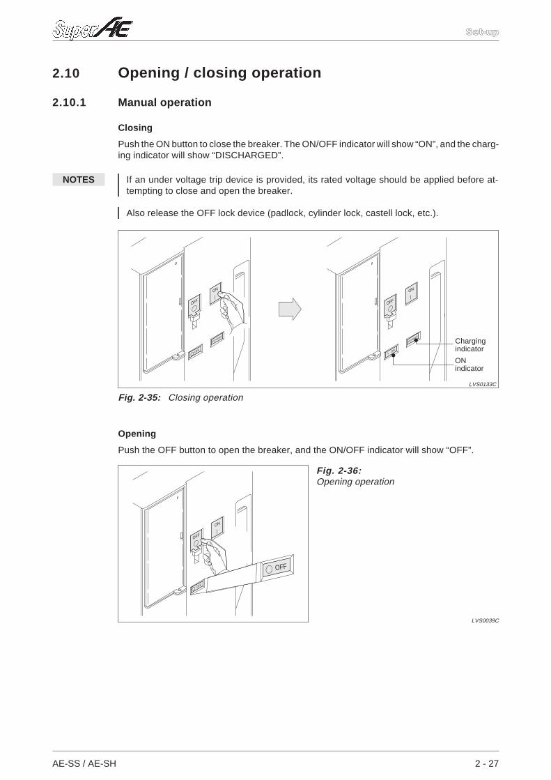
Closing
Push the ON button to close the breaker. The ON/OFF indicator will show “ON”, and the charg-ing indicator will show “DISCHARGED”.
NOTES If an under voltage trip device is provided, its rated voltage should be applied before at-tempting to close and open the breaker.
Also release the OFF lock device (padlock, cylinder lock, castell lock, etc.).
Opening
Push the OFF button to open the breaker, and the ON/OFF indicator will show “OFF”.
AE-SS / AE-SH 2 - 27
Set-up
OFF
OFF
DISCHARGED
ON
OFF
ON
DISCHARGED
ON
Fig. 2-35: Closing operation
LVS0133C
Chargingindicator
ONindicator
OFF
OFF
OFF
ON
Fig. 2-36:Opening operation
LVS0039C
2.10.2 Electrical operation
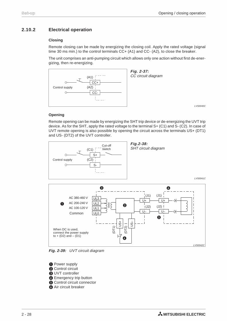
Closing
Remote closing can be made by energizing the closing coil. Apply the rated voltage (signaltime 30 ms min.) to the control terminals CC+ (A1) and CC- (A2), to close the breaker.
The unit comprises an anti-pumping circuit which allows only one action without first de-ener-gizing, then re-energizing.
Opening
Remote opening can be made by energizing the SHT trip device or de-energizing the UVT tripdevice. As for the SHT, apply the rated voltage to the terminal S+ (C1) and S- (C2). In case ofUVT remote opening is also possible by opening the circuit across the terminals US+ (DT1)and US- (DT2) of the UVT controller.
Power supply Control circuit UVT controller Emergency trip button Control circuit connector Air circuit breaker
2 - 28 MITSUBISHI ELECTRIC
Set-up Opening / closing operation
CC+
CC-
(A1)
(A2)
Fig. 2-37:CC circuit diagram
LVS0040C
Control supply
S+
S-
(C1)
(C2)
Fig.2-38:SHT circuit diagram
LVS0041C
Control supply
Cut-offswitch
UL3
UL2
UL1
UL0
U+
U– U–
U+
US
+
US
–
(J1)
(DT
1)
(DT
2)
(J2)
(J1)
(J2)
AC 380-460 V
AC 200-240 V
AC 100-120 V
Summe
Fig. 2-39: UVT circuit diagram
LVS0042C
When DC is used,connect the power supplyto + (D2) and – (D1)
Common
2.11 Operation of the drawout mechanism
2.11.1 Drawout operation
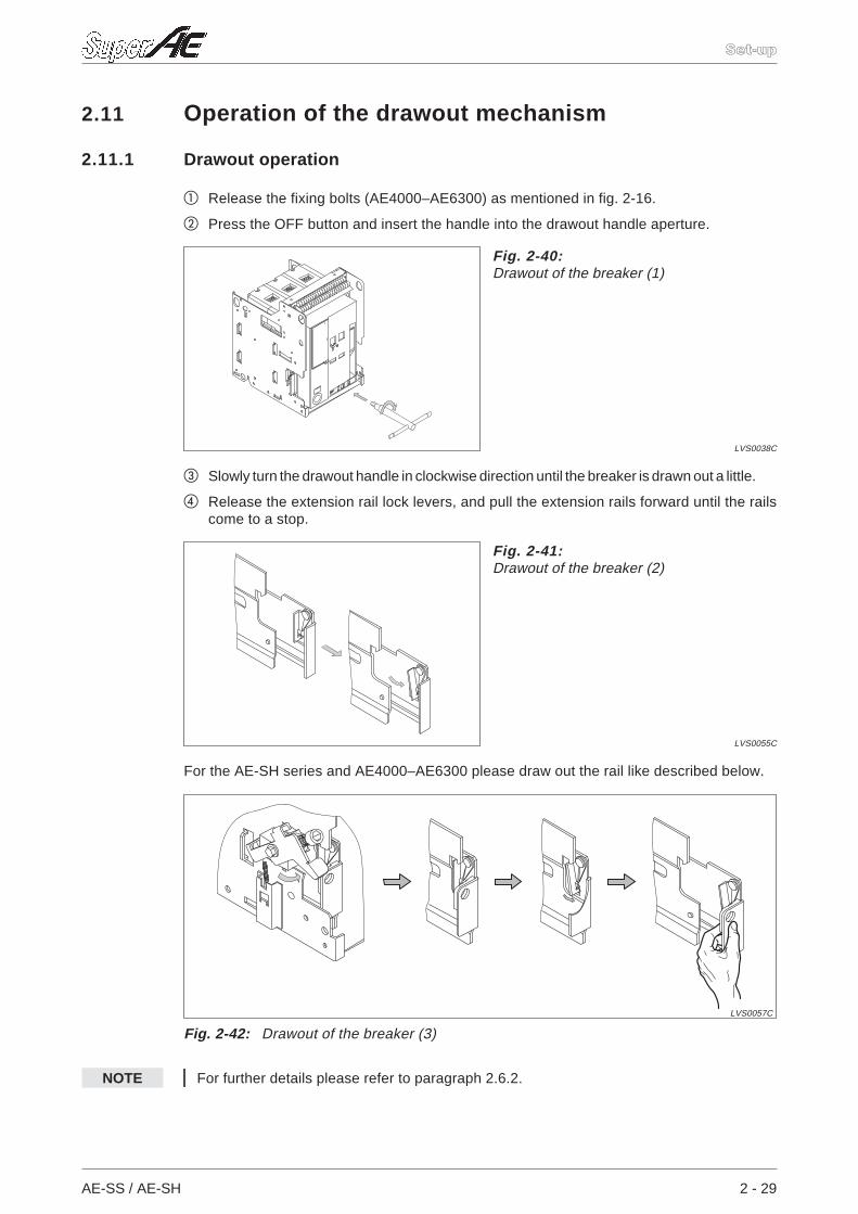
Release the fixing bolts (AE4000–AE6300) as mentioned in fig. 2-16.
Press the OFF button and insert the handle into the drawout handle aperture.
Slowly turn the drawout handle in clockwise direction until the breaker is drawn out a little.
Release the extension rail lock levers, and pull the extension rails forward until the railscome to a stop.
For the AE-SH series and AE4000–AE6300 please draw out the rail like described below.
NOTE For further details please refer to paragraph 2.6.2.
AE-SS / AE-SH 2 - 29
Set-up
Fig. 2-40:Drawout of the breaker (1)
LVS0038C
Fig. 2-41:Drawout of the breaker (2)
LVS0055C
Fig. 2-42: Drawout of the breaker (3)
LVS0057C
2.11.2 Insert operation
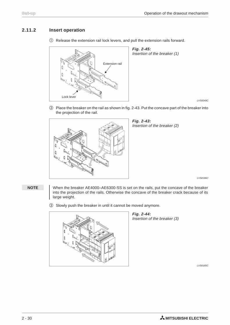
Release the extension rail lock levers, and pull the extension rails forward.
Place the breaker on the rail as shown in fig. 2-43. Put the concave part of the breaker intothe projection of the rail.
NOTE When the breaker AE4000–AE6300-SS is set on the rails, put the concave of the breakerinto the projection of the rails. Otherwise the concave of the breaker crack because of itslarge weight.
Slowly push the breaker in until it cannot be moved anymore.
2 - 30 MITSUBISHI ELECTRIC
Set-up Operation of the drawout mechanism
Fig. 2-43:Insertion of the breaker (2)
LVS0186C
Fig. 2-44:Insertion of the breaker (3)
LVS0185C
Fig. 2-45:Insertion of the breaker (1)
LVS0049C
Lock lever
Extension rail
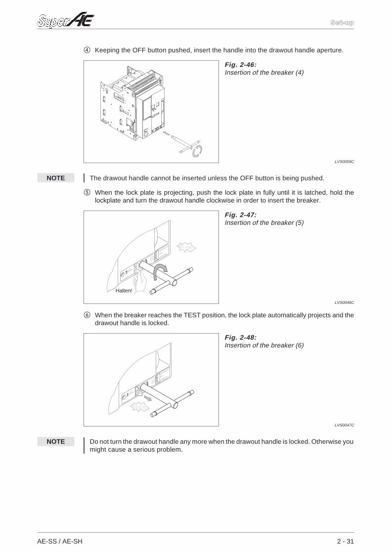
Keeping the OFF button pushed, insert the handle into the drawout handle aperture.
NOTE The drawout handle cannot be inserted unless the OFF button is being pushed.
When the lock plate is projecting, push the lock plate in fully until it is latched, hold thelockplate and turn the drawout handle clockwise in order to insert the breaker.
When the breaker reaches the TEST position, the lock plate automatically projects and thedrawout handle is locked.
NOTE Do not turn the drawout handle any more when the drawout handle is locked. Otherwise youmight cause a serious problem.
AE-SS / AE-SH 2 - 31
Set-up
Fig. 2-46:Insertion of the breaker (4)
LVS0059C
CLICK
Fig. 2-47:Insertion of the breaker (5)
LVS0046C
Halten!
CLICK
Fig. 2-48:Insertion of the breaker (6)
LVS0047C
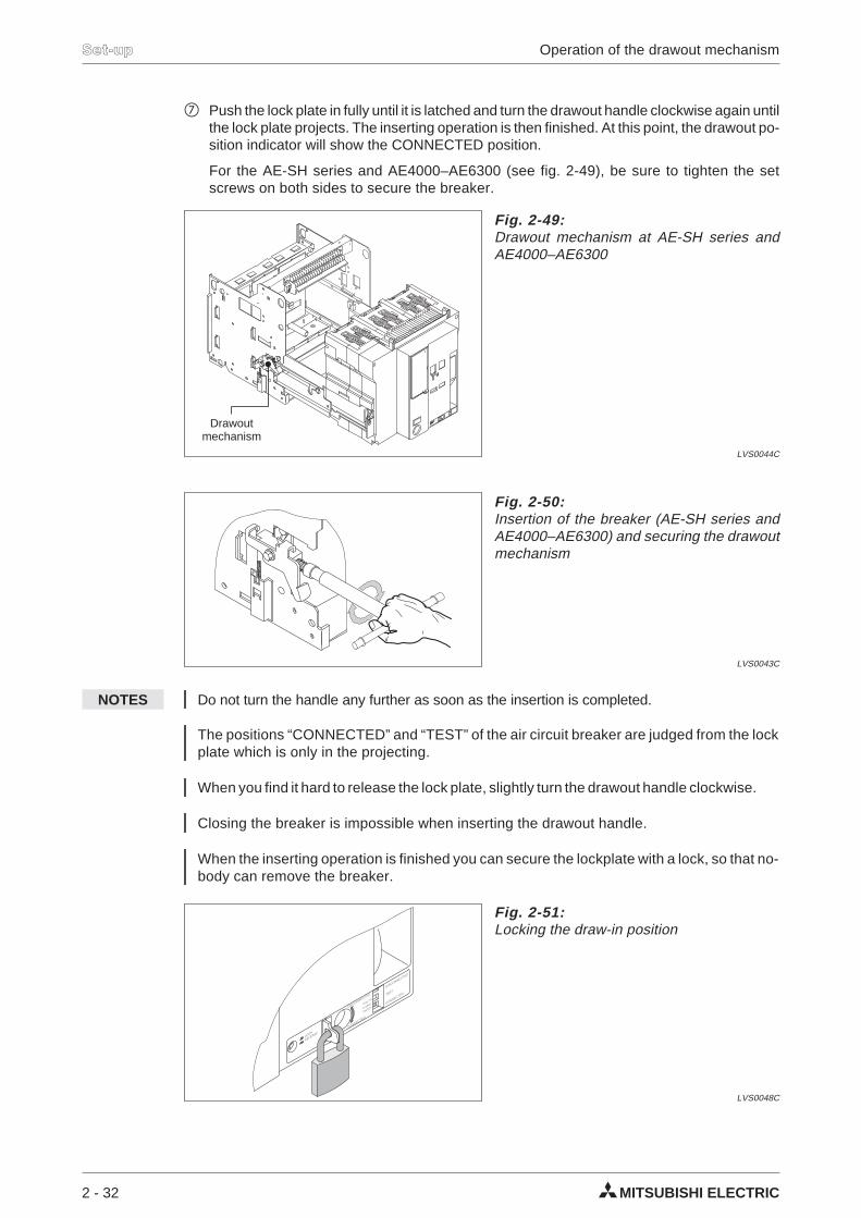
Push the lock plate in fully until it is latched and turn the drawout handle clockwise again untilthe lock plate projects. The inserting operation is then finished. At this point, the drawout po-sition indicator will show the CONNECTED position.
For the AE-SH series and AE4000–AE6300 (see fig. 2-49), be sure to tighten the setscrews on both sides to secure the breaker.
NOTES Do not turn the handle any further as soon as the insertion is completed.
The positions “CONNECTED” and “TEST” of the air circuit breaker are judged from the lockplate which is only in the projecting.
When you find it hard to release the lock plate, slightly turn the drawout handle clockwise.
Closing the breaker is impossible when inserting the drawout handle.
When the inserting operation is finished you can secure the lockplate with a lock, so that no-body can remove the breaker.
2 - 32 MITSUBISHI ELECTRIC
Set-up Operation of the drawout mechanism
Fig. 2-49:Drawout mechanism at AE-SH series andAE4000–AE6300
LVS0044C
Drawoutmechanism
Fig. 2-50:Insertion of the breaker (AE-SH series andAE4000–AE6300) and securing the drawoutmechanism
LVS0043C
Fig. 2-51:Locking the draw-in position
LVS0048C
3 Operation
3.1 Setting the operating characteristicsWhen using the digital relay, please refer to the corresponding manual.
3.1.1 Setting procedure
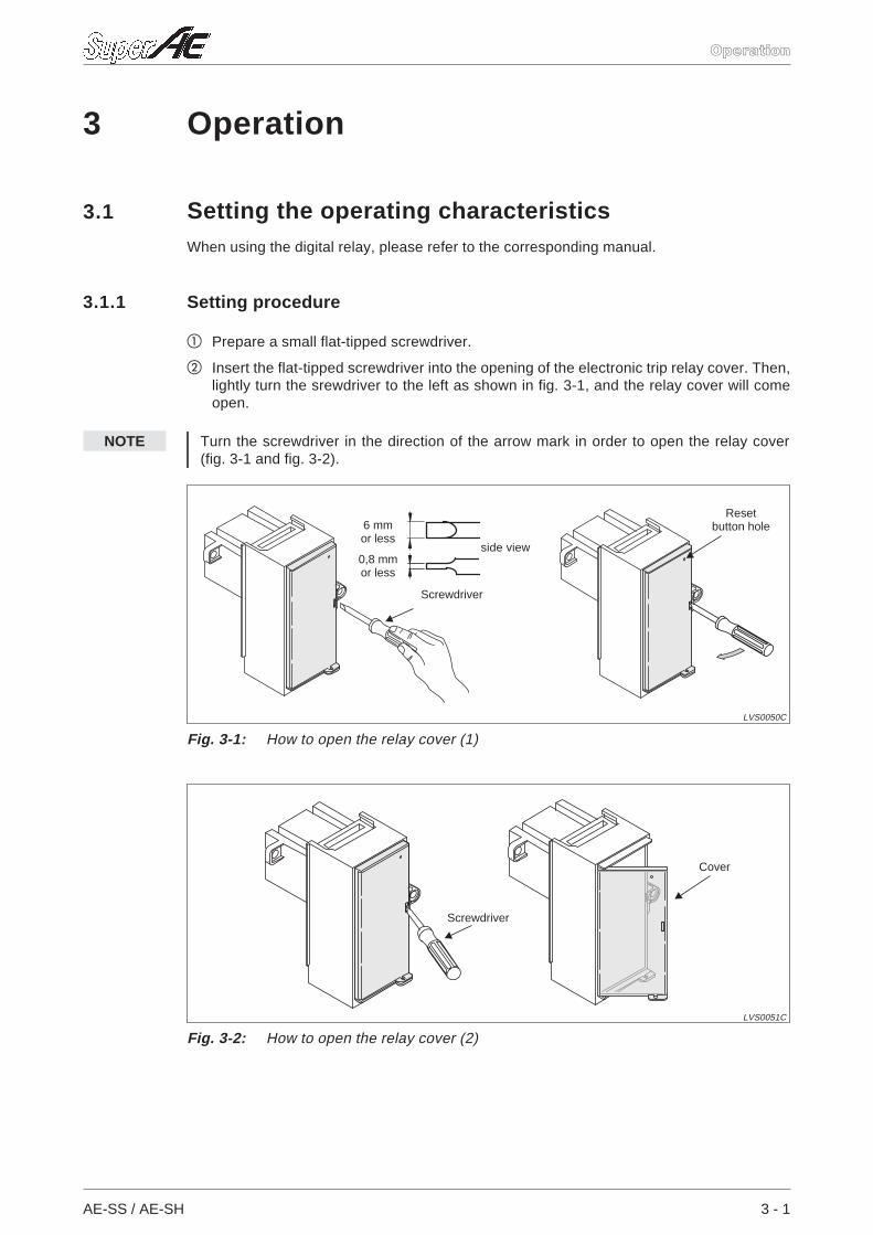
Prepare a small flat-tipped screwdriver.
Insert the flat-tipped screwdriver into the opening of the electronic trip relay cover. Then,lightly turn the srewdriver to the left as shown in fig. 3-1, and the relay cover will comeopen.
NOTE Turn the screwdriver in the direction of the arrow mark in order to open the relay cover(fig. 3-1 and fig. 3-2).
AE-SS / AE-SH 3 - 1
Operation
Fig. 3-1: How to open the relay cover (1)
LVS0050C
6 mmor less
0,8 mmor less
side view
Resetbutton hole
Screwdriver
Fig. 3-2: How to open the relay cover (2)
LVS0051C
Cover
Screwdriver
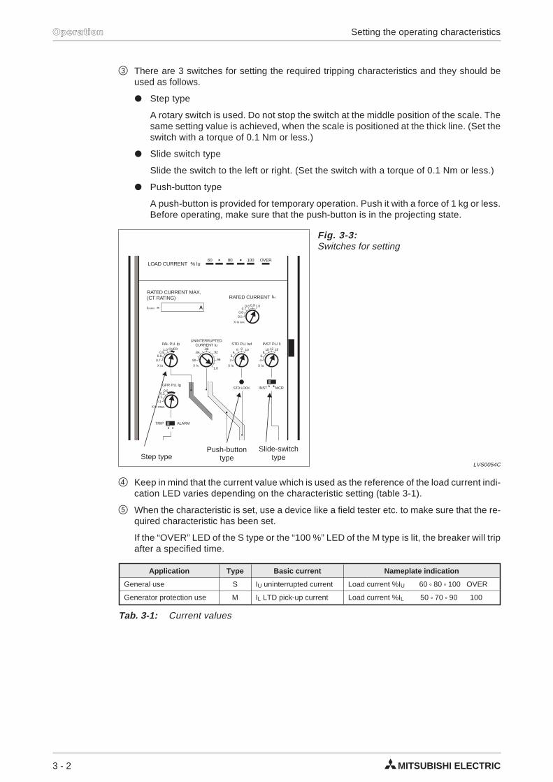
There are 3 switches for setting the required tripping characteristics and they should beused as follows.
Step type
A rotary switch is used. Do not stop the switch at the middle position of the scale. Thesame setting value is achieved, when the scale is positioned at the thick line. (Set theswitch with a torque of 0.1 Nm or less.)
Slide switch type
Slide the switch to the left or right. (Set the switch with a torque of 0.1 Nm or less.)
Push-button type
A push-button is provided for temporary operation. Push it with a force of 1 kg or less.Before operating, make sure that the push-button is in the projecting state.
Keep in mind that the current value which is used as the reference of the load current indi-cation LED varies depending on the characteristic setting (table 3-1).
When the characteristic is set, use a device like a field tester etc. to make sure that the re-quired characteristic has been set.
If the “OVER” LED of the S type or the “100 %” LED of the M type is lit, the breaker will tripafter a specified time.
3 - 2 MITSUBISHI ELECTRIC
Operation Setting the operating characteristics
X Iu
INST P.U. li
46
810 12 16
0.50.6
0.70.8 0.9 1.0
X Iu
STD P.U. lsd
STD LOCK
23
46 8 10
60 80 100 OVER
RATED CURRENT MAX.(CT RATING) RATED CURRENT
LOAD CURRENT % lu
X IN MAX
AIN MAX
UNINTERRUPTEDCURRENT Iu
X IN
.80
.84.88
.92
.96
1.0X Iu
PAL P.U. Ip
INST MCR
0.70.8
0.91.0 OVER
X In max.
GFR P.U. lg
0.10.2
0.30.5
TRIP ALARM
Fig. 3-3:Switches for setting
LVS0054CStep type
Push-buttontype
Slide-switchtype
Application Type Basic current Nameplate indication
General use S IU uninterrupted current Load current %IU 60 80 100 OVER
Generator protection use M IL LTD pick-up current Load current %IL 50 70 90 100
Tab. 3-1: Current values
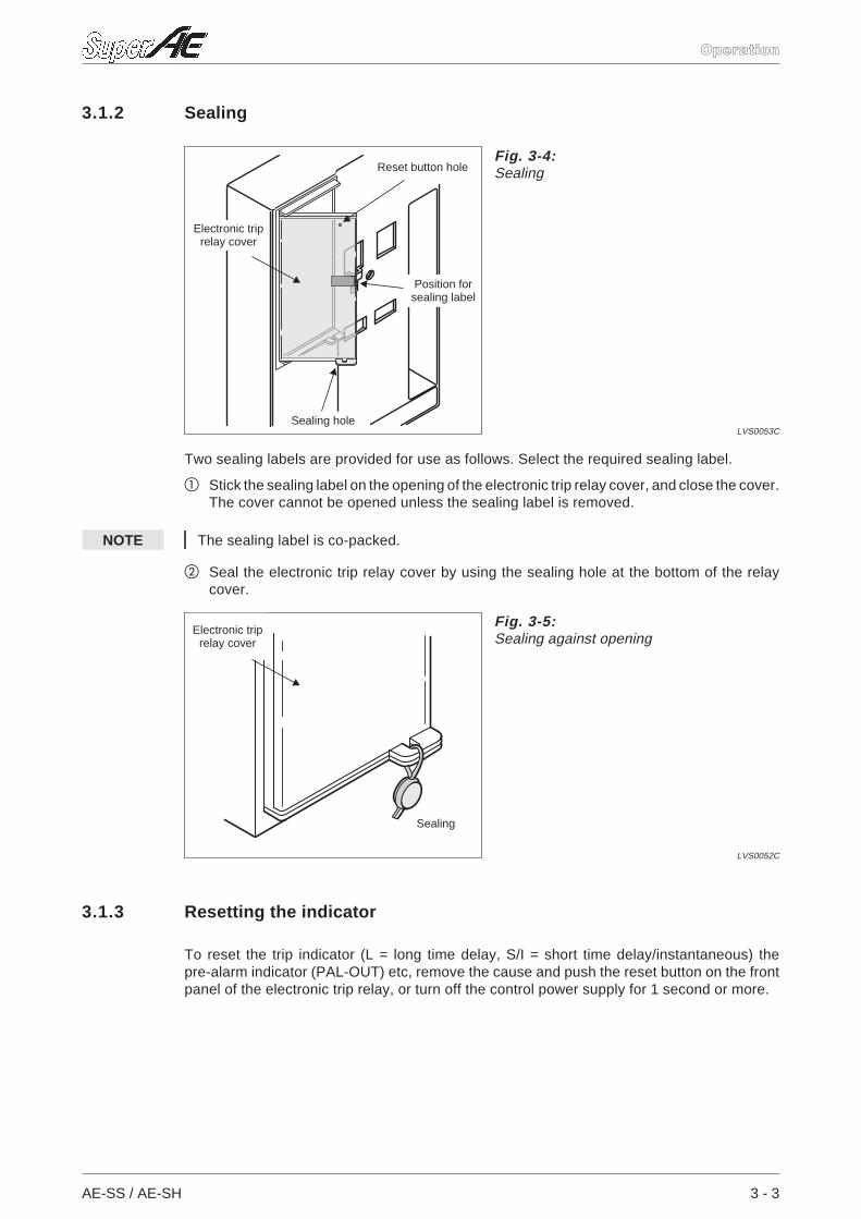
3.1.2 Sealing
Two sealing labels are provided for use as follows. Select the required sealing label.
Stick the sealing label on the opening of the electronic trip relay cover, and close the cover.The cover cannot be opened unless the sealing label is removed.
NOTE The sealing label is co-packed.
Seal the electronic trip relay cover by using the sealing hole at the bottom of the relaycover.
3.1.3 Resetting the indicator
To reset the trip indicator (L = long time delay, S/I = short time delay/instantaneous) thepre-alarm indicator (PAL-OUT) etc, remove the cause and push the reset button on the frontpanel of the electronic trip relay, or turn off the control power supply for 1 second or more.
AE-SS / AE-SH 3 - 3
Operation
Fig. 3-4:Sealing
LVS0053C
Reset button hole
Electronic triprelay cover
Sealing hole
Position forsealing label
Fig. 3-5:Sealing against opening
LVS0052C
Electronic triprelay cover
Sealing
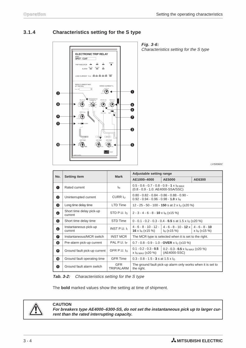
3.1.4 Characteristics setting for the S type
The bold marked values show the setting at time of shipment.
ECAUTIONFor breakers type AE4000–6300-SS, do not set the instantaneous pick up to larger cur-rent than the rated interrupting capacity.
3 - 4 MITSUBISHI ELECTRIC
Operation Setting the operating characteristics
X Iu
INST P.U. li
46
810 12 16
0.50.6
0.70.8 0.9 1.0
X Iu
STD P.U. lsd
STD LOCK
23
46 8 10
TRIP INDICATORL S/I G
PAL P.U.
60 80 100 OVER
RESET
TALALARM
RATED CURRENT MAX.(CT RATING) RATED CURRENT
LOAD CURRENT % lu
SPGT - C1AT
ELECTRONIC TRIP RELAYMODEL
X IN MAX
AIN MAX
UNINTERRUPTEDCURRENT Iu
X IN
.80
.84.88
.92
.96
1.0X Iu
PAL P.U. Ip
INST MCR
0.70.8
0.91.0 OVER
X In max.
GFR P.U. lg
0.10.2
0.30.5
GFR TIME
SEC.SEC.
0.30.30.80.8
1.51.53.03.0
LTD TIME
TEST
SEC.
lu X 2 lsd X 1.5
1225
50100150
STD TIME
SEC.
MADE IN JAPAN
00.10.2
0.3 0.4 0.5
PAL OUT
TRIP ALARM
Fig. 3-6:Characteristics setting for the S type
LVS0060C
No. Setting item MarkAdjustable setting range
AE1000–4000 AE5000 AE6300
Rated current IN0.5 - 0.6 - 0.7 - 0.8 - 0.9 - 1 x IN MAX(0.8 - 0.9 - 1.0: AE4000-SSA/SSC)
Uninterrupted current CURR IU0.80 - 0.82 - 0.84 - 0.86 - 0.88 - 0.90 -0.92 - 0.94 - 0.96 - 0.98 - 1.0 x IN
Long time delay time LTD Time 12 - 25 - 50 - 100 - 150 s at 2 x IU (±20 %)
Short time delay pick-upcurrent
STD P.U. IS 2 - 3 - 4 - 6 - 8 - 10 x IN (±15 %)
Short time delay time STD Time 0 - 0.1 - 0.2 - 0.3 - 0.4 - 0.5 s at 1.5 x IS (±20 %)
Instantaneous pick-upcurrent
INST P.U. II4 - 6 - 8 - 10 - 12 -16 x IN (±15 %)
4 - 6 - 8 - 10 - 12 xIN (±15 %)
4 - 6 - 8 - 10x IN (±15 %)
Instantaneous/MCR switch INST MCR The MCR type is selected when it is set to the right.
Pre-alarm pick-up current PAL P.U. IP 0.7 - 0.8 - 0.9 - 1.0 - OVER x IU (±10 %)
Ground fault pick-up current GFR P.U. IG0.1 - 0.2 - 0.3 - 0.5x IN MAX (±20 %)
0.2 - 0.3 - 0.5 x IN MAX (±20 %)(AE4000-SSC)
Ground fault operating time GFR Time 0.3 - 0.8 - 1.5 - 3 s at 1.5 x IG
Ground fault alarm switch GFRTRIP/ALARM
The ground fault pick-up alarm only works when it is set tothe right.
Tab. 3-2: Characteristics setting for the S type
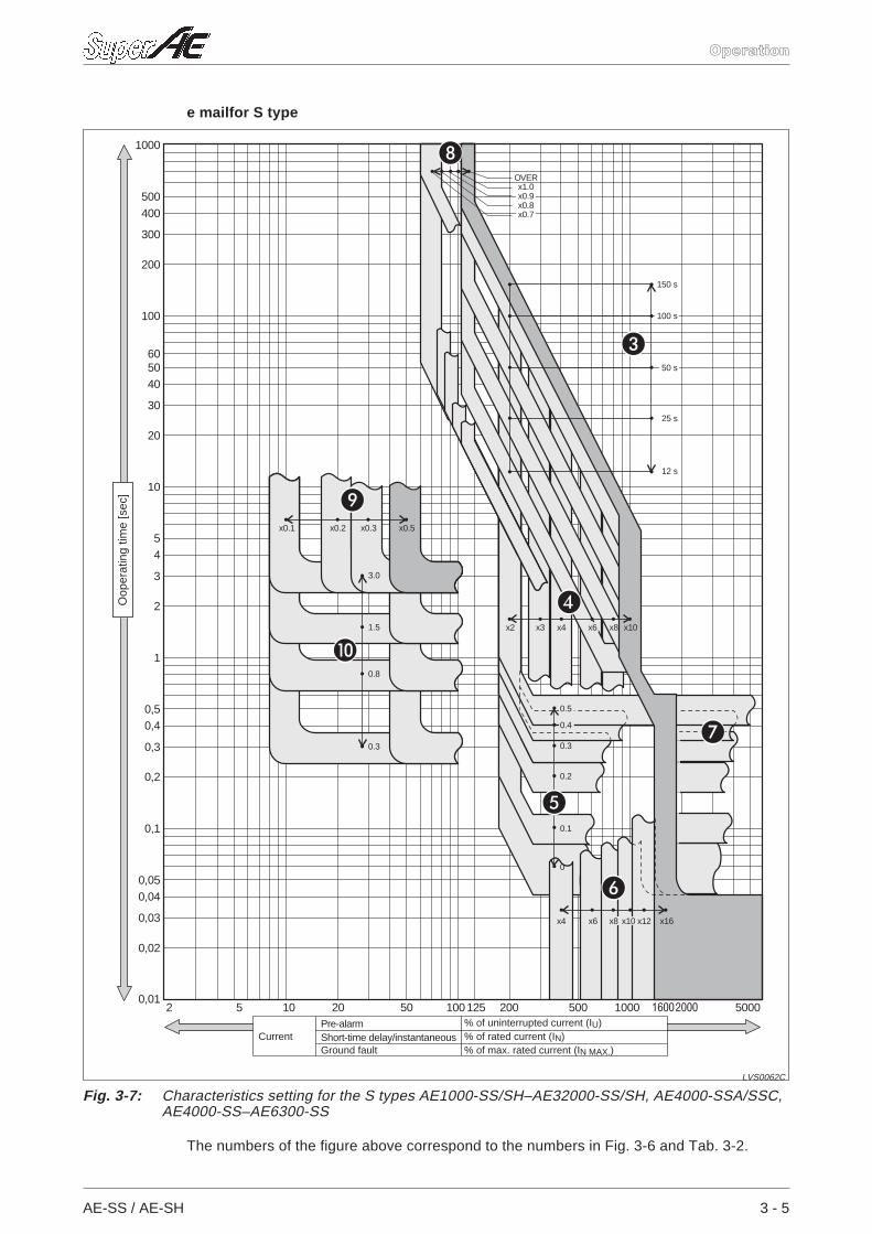
e mailfor S type
The numbers of the figure above correspond to the numbers in Fig. 3-6 and Tab. 3-2.
AE-SS / AE-SH 3 - 5
Operation
1000
500400
300
200
100
605040
30
20
10
54
3
2
1
0,50,4
0,3
0,2
0,1
0,050,04
0,03
0,02
0,012 5 10 20 50 100125 200 500 1000 500016002000
x4 x6 x8 x10 x12 x16
0.5
0.4
0.3
0.2
0.1
0
0.3
0.8
1.5
3.0
x0.1 x0.2 x0.3 x0.5
x2 x3 x4 x6 x8 x10
12 s
25 s
50 s
100 s
150 s
x0.7x0.8x0.9x1.0
OVER
Fig. 3-7: Characteristics setting for the S types AE1000-SS/SH–AE32000-SS/SH, AE4000-SSA/SSC,AE4000-SS–AE6300-SS
LVS0062C
CurrentPre-alarm % of uninterrupted current (IU)Short-time delay/instantaneous % of rated current (IN)Ground fault % of max. rated current (IN MAX.)
Oop
erat
ing
time
[sec
]
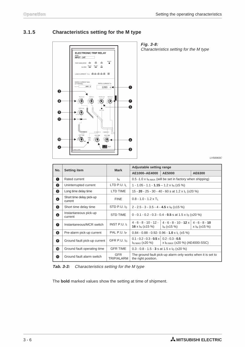
3.1.5 Characteristics setting for the M type
The bold marked values show the setting at time of shipment.
3 - 6 MITSUBISHI ELECTRIC
Operation Setting the operating characteristics
X Iu
INST P.U. li
46
810 12 16
X In
STD P.U. lsd
STD LOCK
22.5
33.5 4 4.5
TRIP INDICATORL S/I
PAL P.U.
50 70 90 100
RESET
PAL OUTALARM
RATED CURRENT MAX.(CT RATING) RATED CURRENT In
LOAD CURRENT % lL
MPGT - 1AT
ELECTRONIC TRIP RELAYMODEL
1600 A AIN MAX
LTD P.U. IL
X In
1.01.05
1.11.21.15
X IL
PAL P.U. Ip
.84.88
.92.96 1.0
LTD TIME
FINE
TEST
s s
l X 2L lsd X 1.5
1520
2530 40 60
STD TIME
MADE IN JAPAN
00.10.2
0.3 0.4 0.5
X In max.
GFR P.U. lg
0.10.2
0.30.5
GFR TIME
SEC.SEC.
0.30.30.80.8
1.51.53.03.0
TRIP ALARM
G
TAL
1283
Fig. 3-8:Characteristics setting for the M type
LVS0063C
No. Setting item MarkAdjustable setting range
AE1000–AE4000 AE5000 AE6300
Rated current IN 0.5 -1.0 x IN MAX (will be set in factory when shipping)
Uninterrupted current LTD P.U. IL 1 - 1.05 - 1.1 - 1.15 – 1.2 x IN (±5 %)
Long time delay time LTD TIME 15 - 20 - 25 - 30 - 40 - 60 s at 1.2 x IL (±20 %)
Short time delay pick-upcurrent FINE 0.8 - 1.0 - 1.2 x TL
Short time delay time STD P.U. IS 2 - 2.5 - 3 - 3.5 - 4 - 4.5 x IN (±15 %)
Instantaneous pick-upcurrent STD TIME 0 - 0.1 - 0.2 - 0.3 - 0.4 - 0.5 s at 1.5 x IS (±20 %)
Instantaneous/MCR switch INST P.U. II4 - 6 - 8 - 10 - 12 -16 x IN (±15 %)
4 - 6 - 8 - 10 - 12 xIN (±15 %)
4 - 6 - 8 - 10x IN (±15 %)
Pre-alarm pick-up current PAL P.U. IP 0.84 - 0.88 - 0.92- 0.96 - 1.0 x IL (±5 %)
Ground fault pick-up current GFR P.U. IG0.1 - 0.2 - 0.3 - 0.5 xIN MAX (±20 %)
0.2 - 0.3 - 0.5x IN MAX (±20 %) (AE4000-SSC)
Ground fault operating time GFR TIME 0.3 - 0.8 - 1.5 - 3 s at 1.5 x IG (±20 %)
Ground fault alarm switch GFRTRIP/ALARM
The ground fault pick-up alarm only works when it is set tothe right position.
Tab. 3-3: Characteristics setting for the M type
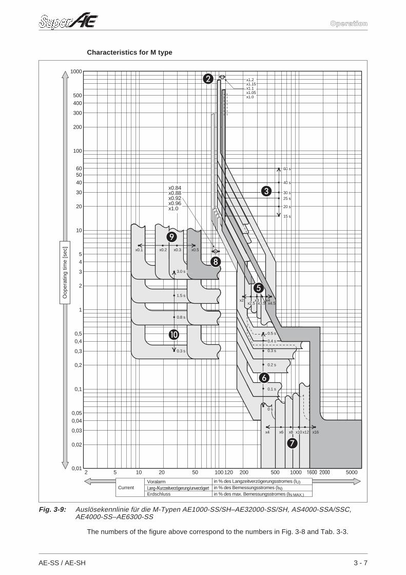
Characteristics for M type
The numbers of the figure above correspond to the numbers in Fig. 3-8 and Tab. 3-3.
AE-SS / AE-SH 3 - 7
Operation
2 5 10 20 50 100 120 200 500 1000 50001600 2000
1000
500400
300
200
100
605040
30
20
10
54
3
2
1
0,50,4
0,3
0,2
0,1
0,050,04
0,03
0,02
0,01
x4 x6 x8 x10x12 x16
0.5 s
0.4 s
0.3 s
0.2 s
0.1 s
0 s
0.3 s
0.8 s
1.5 s
3.0 s
x0.1 x0.2 x0.3 x0.5
x2x2.5
x3x3.5
x4x4.5
15 s
20 s
25 s30 s
40 s
x1.0x1.05x1.1x1.15x1.2
60 s
x0.84x0.88x0.92x0.96x1.0
Fig. 3-9: Auslösekennlinie für die M-Typen AE1000-SS/SH–AE32000-SS/SH, AS4000-SSA/SSC,AE4000-SS–AE6300-SS
Oop
erat
ing
time
[sec
]
CurrentVoralarm in % des Langzeitverzögerungsstromes (IU)
Lang-/Kurzzeitverzögerung/unverzögert in % des Bemessungsstromes (IN)Erdschluss in % des max. Bemessungsstromes (IN MAX.)
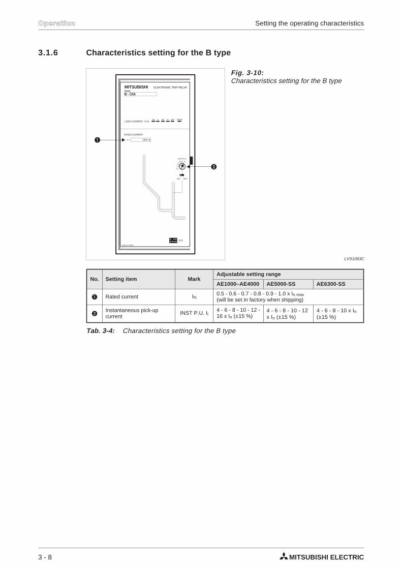
3.1.6 Characteristics setting for the B type
3 - 8 MITSUBISHI ELECTRIC
Operation Setting the operating characteristics
X Iu
INST P.U. li
46
810 12 16
60 80 100 OVER
RATED CURRENT
1600
LOAD CURRENT % ln
B - C0A
MITSUBISHI ELEKTRONIC TRIP RELAYMODEL
AIn
TEST
MADE IN JAPAN
INST MCR
Fig. 3-10:Characteristics setting for the B type
LVS1063C
No. Setting item MarkAdjustable setting range
AE1000–AE4000 AE5000-SS AE6300-SS
Rated current IN0.5 - 0.6 - 0.7 - 0.8 - 0.9 - 1.0 x In max(will be set in factory when shipping)
Instantaneous pick-upcurrent
INST P.U. Ii4 - 6 - 8 - 10 - 12 -16 x In (±15 %)
4 - 6 - 8 - 10 - 12x In (±15 %)
4 - 6 - 8 - 10 x In(±15 %)
Tab. 3-4: Characteristics setting for the B type
Characteristics for the B type
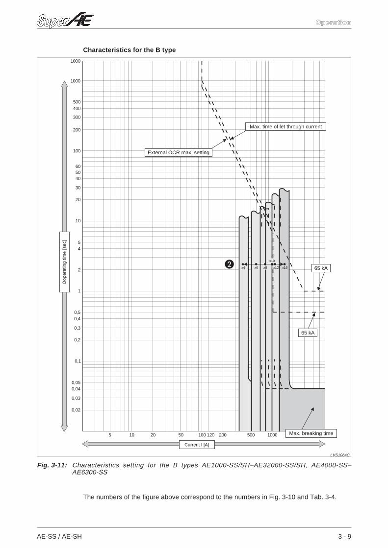
The numbers of the figure above correspond to the numbers in Fig. 3-10 and Tab. 3-4.
AE-SS / AE-SH 3 - 9
Operation
10 1000 2000 5000200100 12020 50 5005
1000
1000
10
1
0,1
200
100
20
2
300
40
30
400
50
4
500
60
5
0,5
0,05
0,4
0,04
0,3
0,03
0,2
0,02
x4 x6 x8
x10
x12 x16
Fig. 3-11: Characteristics setting for the B types AE1000-SS/SH–AE32000-SS/SH, AE4000-SS–AE6300-SS
LVS1064C
Current I [A]
Oop
erat
ing
time
[sec
]
Max. breaking time
External OCR max. setting
Max. time of let through current
65 kA
65 kA
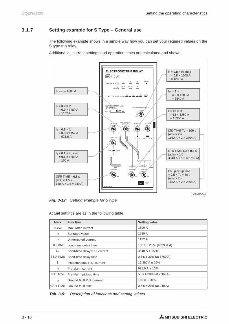
3.1.7 Setting example for S Type – General use
The following example shows in a simple way how you can set your required values on theS type trip relay.
Additional all current settings and operation times are calculated and shown.
Actual settings are as in the following table:
3 - 10 MITSUBISHI ELECTRIC
Operation Setting the operating characteristics
X Iu
INST P.U. li
46
810 12 16
0.50.6
0.70.8 0.9 1.0
X Iu
STD P.U. lsd
STD LOCK
23
46 8 10
TRIP INDICATORL S/I G
PAL P.U.
60 80 100 OVER
RESET
TALALARM
RATED CURRENT MAX.(CT RATING) RATED CURRENT
LOAD CURRENT % lu
SPGT - C1AT
ELECTRONIC TRIP RELAYMODEL
X IN MAX
IN MAX
UNINTERRUPTEDCURRENT Iu
X IN
.80
.84.88
.92
.96
1.0X Iu
PAL P.U. Ip
INST MCR
0.70.8
0.91.0 OVER
X In max.
GFR P.U. lg
0.10.2
0.30.5
GFR TIME
SEC.SEC.
0.30.30.80.8
1.51.53.03.0
LTD TIME
TEST
SEC.
lu X 2 lsd X 1.5
1225
50100150
STD TIME
SEC.
MADE IN JAPAN
00.10.2
0.3 0.4 0.5
PAL OUT
TRIP ALARM
1600 A
I = 1600 An, max
I = × In, max= × 1600 A= 1280 A
n 0.80.8I
In
n
I = × In= × 1280 A= 1152 A
u 0.90.9I
In
n
I = × Iu= × 1152 A= 921,6 A
p 0.80.8I
Ip
p
I = × In, max= × 1600 A= 160 A
g 0.10.1I
Ig
g
GFR TIME = sI × 1.5 =
160 A × 1.5 = 240 A)
0.8g(at
I = × In= × 1280 A= 3840 A
sd 33I
Isd
sd
I = × In= × 1280 A= 15360 A
i 1212I
Ii
i
LTD TIME TL = sI × 2 =
1152 A × 2 = 2304 A)
100u(at
STD TIME T = sI × 1.5 =
3840 A × 1.5 = 5760 A)
sd
sd
0.3(at
PAL pick-up time= × T = 50 s(at I × 2 =1152 A × 2 = 2304 A)
0.5 L
u
Fig. 3-12: Setting example for S type
LVS1065C-gb
Mark Function Setting value
In, max Max. rated current 1600 A
In Set rated value 1280 A
Iu Uniterrupted current 1152 A
LTD TIME Long-time delay time 100 s ± 20 % (at 2304 A)
Isd Short-time delay P.U. current 3840 A ± 15 %
STD TIME Short-time delay time 0.3 s ± 20% (at 5760 A)
Ii Instantaneous P.U. current 15,360 A ± 15%
Ip Pre-alarm current 921.6 A ± 10%
PAL time Pre-alarm pick-up time 50 s ± 20% (at 2304 A)
Ig Ground fault P.U. current 160 A ± 20%
GFR TIME Ground fault time 0.8 s ± 20% (at 240 A)
Tab. 3-5: Description of functions and setting values
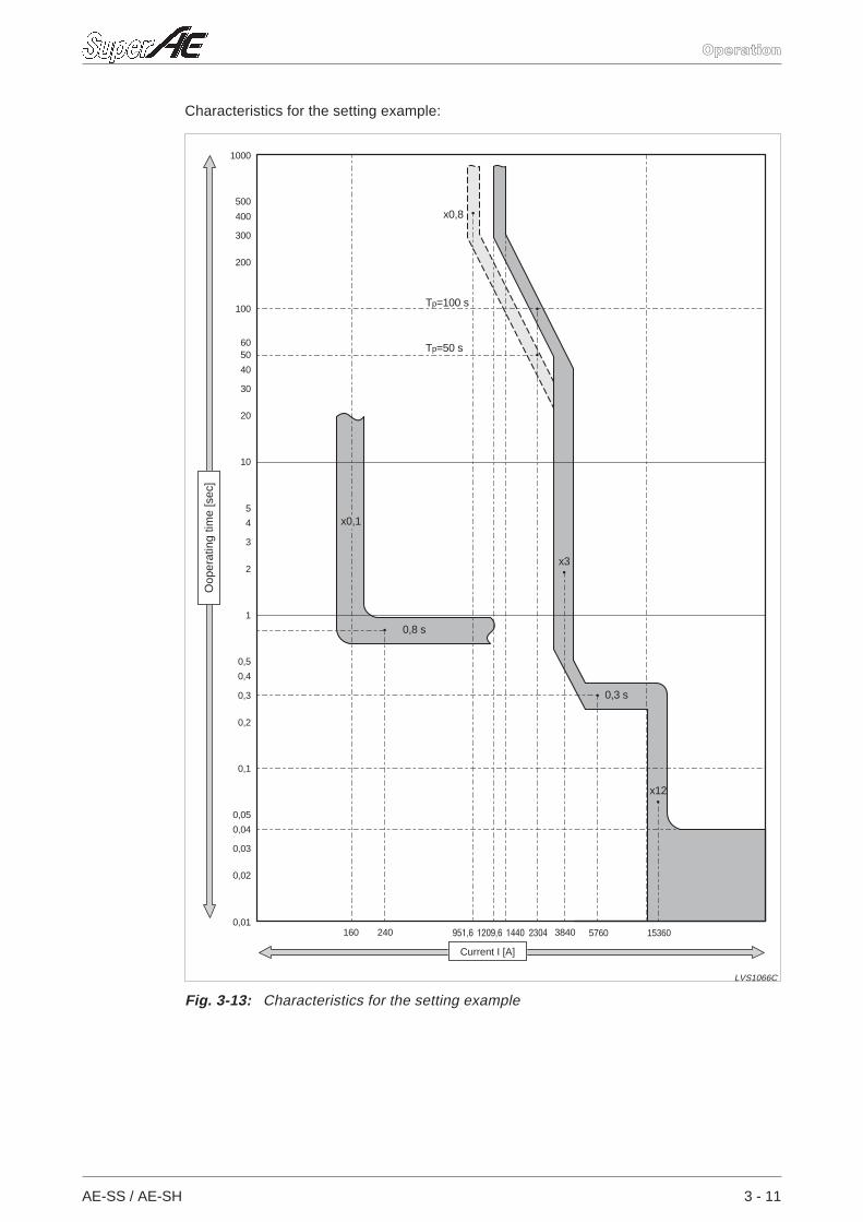
Characteristics for the setting example:
AE-SS / AE-SH 3 - 11
Operation
0,8 s
x0,1
1000
500
400
300
200
100
6050
40
30
20
10
5
4
3
2
1
0,5
0,4
0,3
0,2
0,1
0,05
0,04
0,03
0,02
0,01160 240 951,6 1209,6 1440 2304 3840 153605760
x0,8
x3
T =100 sp
T =50 sp
x12
0,3 s
Fig. 3-13: Characteristics for the setting example
LVS1066C
Current I [A]
Oop
erat
ing
time
[sec
]
3.1.8 Operating system of each device
NOTE A circuit diagram of the electronic trip relay is shown on the next page.
Power supply CT
Operation energy is supplied to the overcurrent tripping and ground fault tripping function(GFR) of the electronic trip relay.
Current sensor coil
The current of each phase which flows in the breaker is detected. A coreless coil with goodlinearity is employed. The integrated circuit integrates the output voltage and bears thesignal waveform which is in proportion with the load current.
LTD circuit
This is an effective value detection type which is strong against the distorted wave. It has amemory effect for the over-current state. If the electronic trip relay is tripped, the over-cur-rent memory is reset.
Pre-alarm circuit
This is an effective value detection system. As it does not have a memory effect for theover-current state, once the current becomes less than the value of the pre-alarm settingcurrent, it is reset to the former state.
STD/INST circuit
This is a peak value detection system which is influenced by the distortion of the waveform.
Ground fault circuit
The signals in each phases are summed up in the vector mode in order to gain the groundfault value.
Current measuring output circuit
This is an effective value detection system. Since insulation amplifiers are used, it is insu-lated between the input and the output.
OCR alarm circuit
1 pulse 30 ms signal output without control power supply
3 - 12 MITSUBISHI ELECTRIC
Operation Setting the operating characteristics
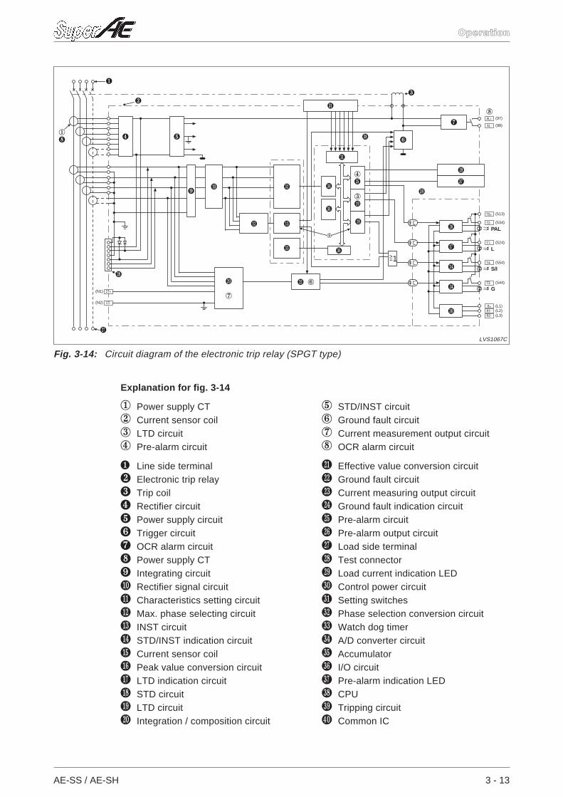
Explanation for fig. 3-14
1 Power supply CT 5 STD/INST circuit2 Current sensor coil 6 Ground fault circuit3 LTD circuit 7 Current measurement output circuit4 Pre-alarm circuit 8 OCR alarm circuit
! Line side terminal bk Effective value conversion circuit“ Electronic trip relay bl Ground fault circuit§ Trip coil bm Current measuring output circuit$ Rectifier circuit bn Ground fault indication circuit% Power supply circuit bo Pre-alarm circuit& Trigger circuit bp Pre-alarm output circuit/ OCR alarm circuit bq Load side terminal( Power supply CT br Test connector) Integrating circuit bs Load current indication LEDat Rectifier signal circuit ct Control power circuitak Characteristics setting circuit ck Setting switchesal Max. phase selecting circuit cl Phase selection conversion circuitam INST circuit cm Watch dog timeran STD/INST indication circuit cn A/D converter circuitao Current sensor coil co Accumulatorap Peak value conversion circuit cp I/O circuitaq LTD indication circuit cq Pre-alarm indication LEDar STD circuit cr CPUas LTD circuit cs Tripping circuitbt Integration / composition circuit dt Common IC
AE-SS / AE-SH 3 - 13
Operation
CT+
AL+
T0+
T2-
T1-
T4-
T3-
R+R1-R2-
(N1)
(97)
(513)
(534)
(524)
(554)
(544)
(L1)(L2)(L3)
(N2) CT-
(98)AL-
>=1
1(
!
"
$
§
/
8
bs
bp
aq
an
bn
ct
bl 6bt
7
br
bq
)at
ak
al am
&
cm
cl
ck
cn
co
4bo
3as
ar
5
cr
cs
cq
cp
PAL
L
S/I
G
%
Fig. 3-14: Circuit diagram of the electronic trip relay (SPGT type)
LVS1067C
3.2 Checking the tripping characteristics
3.2.1 Checking with a field tester (Y-160 and Y-2000)
If the test power supply or the simulation signal is applied to the test terminals of the electronictrip relay, the overcurrent tripping characteristics or ground fault operating characteristics caneasily be measured.
Two models are available:
Model Y160 is a small battery type.
Model Y-2000 which can measure all the characteristics.
NOTE If any current flows in the main circuit of the breaker, the proper characteristics will not bemeasured since the current will distort the simulation signal of the test. Therefore, ensurethat the test is conducted when the load current does not exist in the main circuit.
In order to remove any influence which may result from energization before the test, trip thebreaker once with the trip check before measuring the LTD time.
The instantaneous tripping current is the value measured when the breaker is tripping, grad-ually by increasing the overcurrent signal (OS) during pressing the switch “STD LOCK”(when model Y-2000 is used).
3 - 14 MITSUBISHI ELECTRIC
Operation Checking the tripping characteristics
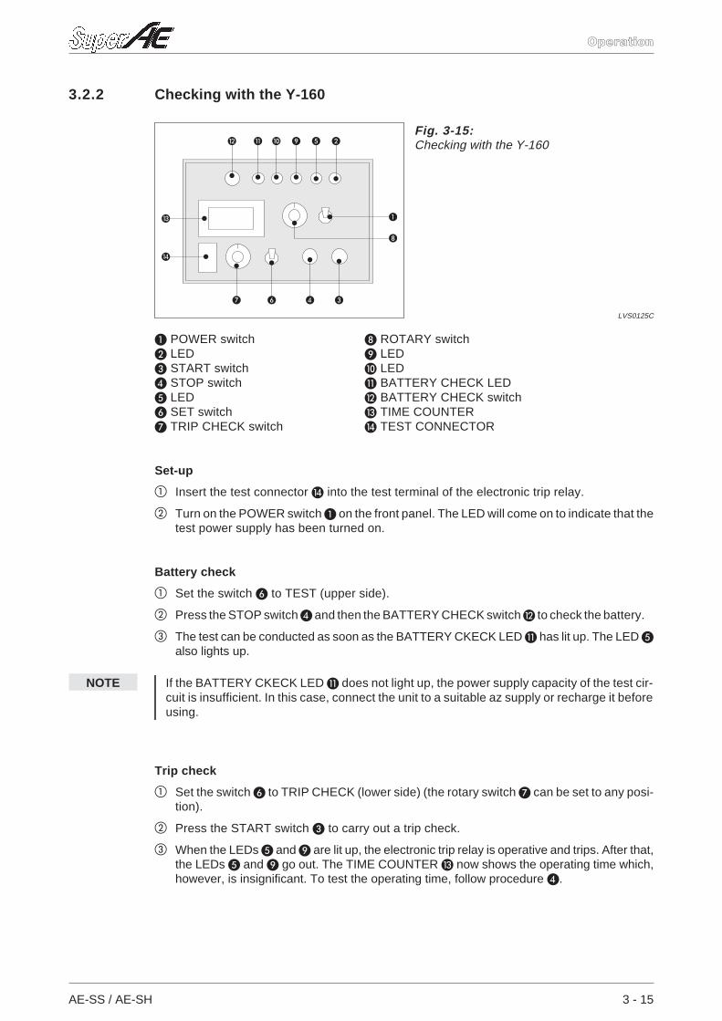
3.2.2 Checking with the Y-160
POWER switch ROTARY switch LED LED START switch LED STOP switch BATTERY CHECK LED LED BATTERY CHECK switch SET switch TIME COUNTER TRIP CHECK switch TEST CONNECTOR
Set-up
Insert the test connector into the test terminal of the electronic trip relay.
Turn on the POWER switch on the front panel. The LED will come on to indicate that thetest power supply has been turned on.
Battery check
Set the switch to TEST (upper side).
Press the STOP switch and then the BATTERY CHECK switch to check the battery.
The test can be conducted as soon as the BATTERY CKECK LED has lit up. The LED also lights up.
NOTE If the BATTERY CKECK LED does not light up, the power supply capacity of the test cir-cuit is insufficient. In this case, connect the unit to a suitable az supply or recharge it beforeusing.
Trip check
Set the switch to TRIP CHECK (lower side) (the rotary switch can be set to any posi-tion).
Press the START switch to carry out a trip check.
When the LEDs and are lit up, the electronic trip relay is operative and trips. After that,the LEDs and go out. The TIME COUNTER now shows the operating time which,however, is insignificant. To test the operating time, follow procedure .
AE-SS / AE-SH 3 - 15
Operation
Fig. 3-15:Checking with the Y-160
LVS0125C
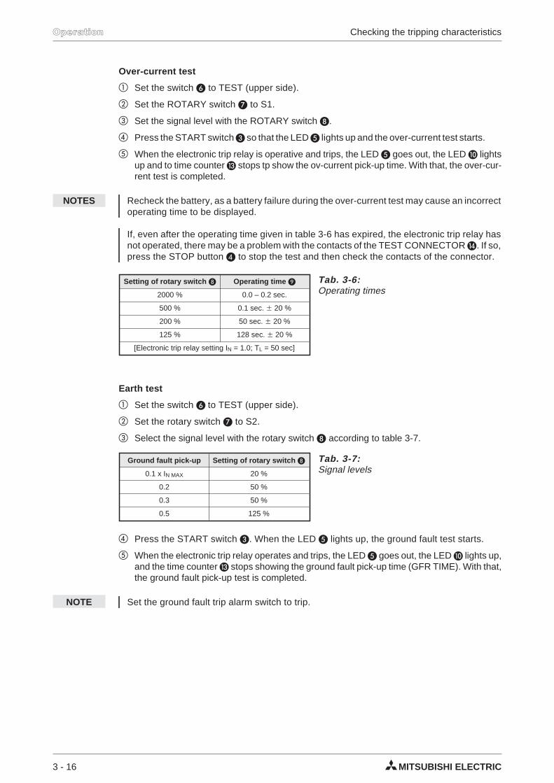
Over-current test
Set the switch to TEST (upper side).
Set the ROTARY switch to S1.
Set the signal level with the ROTARY switch .
Press the START switch so that the LED lights up and the over-current test starts.
When the electronic trip relay is operative and trips, the LED goes out, the LED lightsup and to time counter stops tp show the ov-current pick-up time. With that, the over-cur-rent test is completed.
NOTES Recheck the battery, as a battery failure during the over-current test may cause an incorrectoperating time to be displayed.
If, even after the operating time given in table 3-6 has expired, the electronic trip relay hasnot operated, there may be a problem with the contacts of the TEST CONNECTOR . If so,press the STOP button to stop the test and then check the contacts of the connector.
Earth test
Set the switch to TEST (upper side).
Set the rotary switch to S2.
Select the signal level with the rotary switch according to table 3-7.
Press the START switch . When the LED lights up, the ground fault test starts.
When the electronic trip relay operates and trips, the LED goes out, the LED lights up,and the time counter stops showing the ground fault pick-up time (GFR TIME). With that,the ground fault pick-up test is completed.
NOTE Set the ground fault trip alarm switch to trip.
3 - 16 MITSUBISHI ELECTRIC
Operation Checking the tripping characteristics
Setting of rotary switch Operating time
2000 % 0.0 – 0.2 sec.
500 % 0.1 sec. 20 %
200 % 50 sec. 20 %
125 % 128 sec. 20 %
[Electronic trip relay setting IN = 1.0; TL = 50 sec]
Tab. 3-6:Operating times
Ground fault pick-up Setting of rotary switch
0.1 x IN MAX 20 %
0.2 50 %
0.3 50 %
0.5 125 %
Tab. 3-7:Signal levels
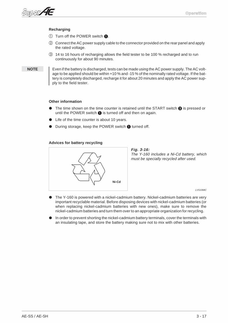
Recharging
Turn off the POWER switch .
Connect the AC power supply cable to the connector provided on the rear panel and applythe rated voltage.
14 to 16 hours of recharging allows the field tester to be 100 % recharged and to runcontinuously for about 90 minutes.
NOTE Even if the battery is discharged, tests can be made using the AC power supply. The AC volt-age to be applied should be within +10 % and -15 % of the nominally rated voltage. If the bat-tery is completely discharged, recharge it for about 20 minutes and apply the AC power sup-ply to the field tester.
Other information
The time shown on the time counter is retained until the START switch is pressed oruntil the POWER switch is turned off and then on again.
Life of the time counter is about 10 years.
During storage, keep the POWER switch turned off.
Advices for battery recycling
The Y-160 is powered with a nickel-cadmium battery. Nickel-cadmium batteries are veryimportant recyclable material. Before disposing devices with nickel-cadmium batteries (orwhen replacing nickel-cadmium batteries with new ones), make sure to remove thenickel-cadmium batteries and turn them over to an appropriate organization for recycling.
In order to prevent shorting the nickel-cadmium battery terminals, cover the terminals withan insulating tape, and store the battery making sure not to mix with other batteries.
AE-SS / AE-SH 3 - 17
Operation
Ni-Cd
Fig. 3-16:The Y-160 includes a Ni-Cd battery, whichmust be specially recycled after used.
LVS1068C
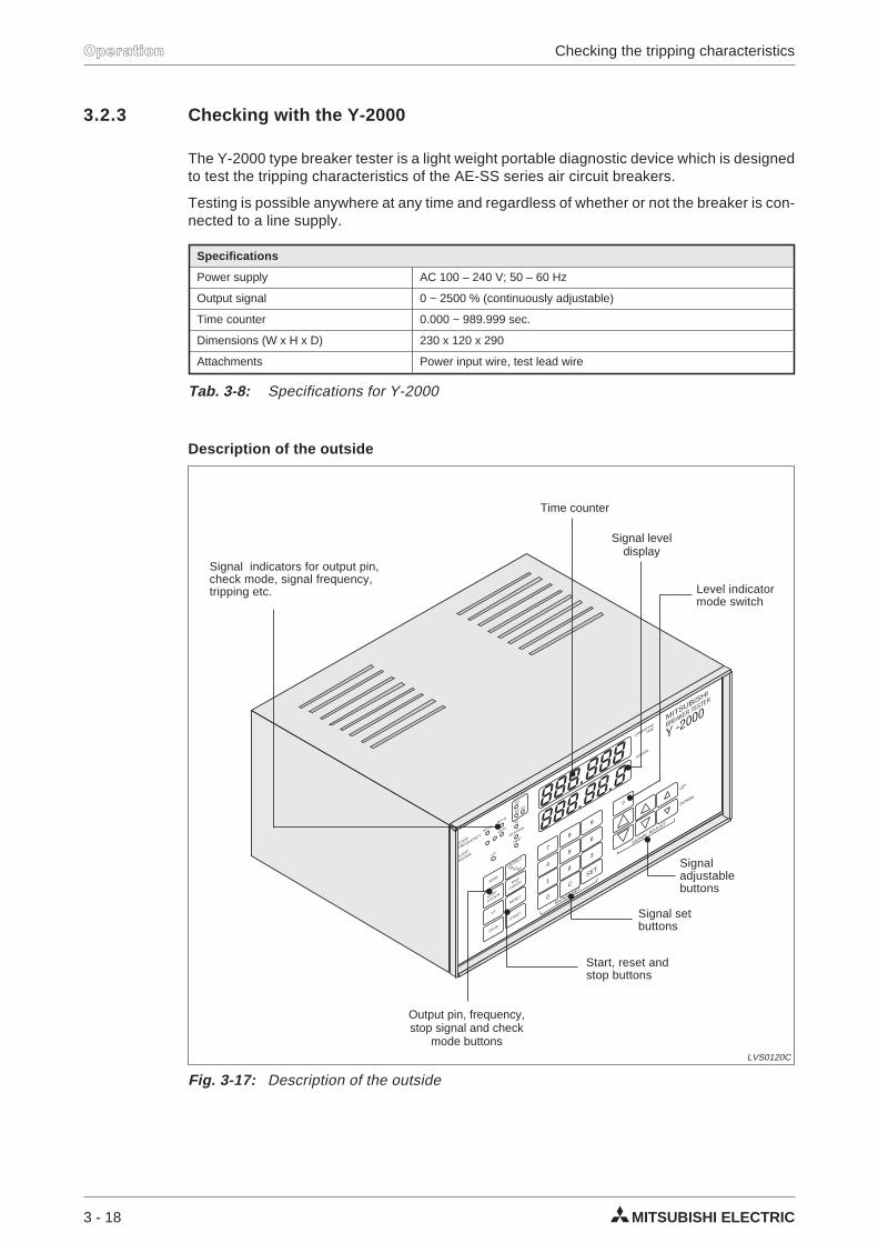
3.2.3 Checking with the Y-2000
The Y-2000 type breaker tester is a light weight portable diagnostic device which is designedto test the tripping characteristics of the AE-SS series air circuit breakers.
Testing is possible anywhere at any time and regardless of whether or not the breaker is con-nected to a line supply.
Description of the outside
3 - 18 MITSUBISHI ELECTRIC
Operation Checking the tripping characteristics
Specifications
Power supply AC 100 – 240 V; 50 – 60 Hz
Output signal 0 ~ 2500 % (continuously adjustable)
Time counter 0.000 ~ 989.999 sec.
Dimensions (W x H x D) 230 x 120 x 290
Attachments Power input wire, test lead wire
Tab. 3-8: Specifications for Y-2000
888.888
888.88.8
STOP
a?/OCR
VT
50/60
50 Hz60 Hz
OCR
VT
TESTING
7
4
1
0
9
6
3
SET
SIGNAL SET
SIGNAL ADJUST
STOP
SIGNAL
STOP
FREQUENCY
SIGNAL
BREAKER TESTER
UP
OPERATING
TIME
DOWN
8
8
8
?
C
OUTPUT
OUTPUT
S1S2S3
S3
S2
TC
S1
STOP
TRIP
CHECK
START
RESET
TRIP
MITSUBISHI
Y -2000
Fig. 3-17: Description of the outside
LVS0120C
Output pin, frequency,stop signal and check
mode buttons
Level indicatormode switch
Time counter
Signal leveldisplay
Start, reset andstop buttons
Signal setbuttons
Signaladjustablebuttons
Signal indicators for output pin,check mode, signal frequency,tripping etc.
Preparation of the test
Remove the front cover by pulling at the two black knobs.
Connect the wire.
Set the time counter and the signal level by turning on the power switch at the back panel.The LED lights up.
Set the test mode with the following switches. By pushing these switches, you select thedifferent modes.
Signal frequency 50 Hz, 60 Hz
Stop signal a, b, OCR
Output pin S1, S2, S3
Check mode Usual test, Trip check
(When the power is turned on, each mode is set on the marked position.)
Setting of the rated current IN
At first, set the rated current IN to the rated current of the electronic trip relay, because thesignal level is represented in % of the rated current IN.
When the power is turned on, IN is 1 x INMAX.
Set the mode (...) by using the level indicator mode switch (...), adjust the ratedcurrent IN to 0.4 – 1 of the max. rated current INMAX by using the signal adjustableswitch or the signal set switch.
Rated current IN = 0.8 x IN,MAXUninterrupted current IU = 1 x IN,MAX
H 0.800
When the uninterrupted current IU is not 1 x IN, set in case of measuring long-time-delayand pre-alarm characteristics as follows.
Rated current IN = 0.5 x IN,MAXUninterrupted current IU = 0.8 x IN = 0.4 x IN,MAX
H 0.400
When the uninterrupted current IU is not 1 x IN, set the rated current value IN evenat any IU setting for STD and INST.
Rated current IN = 0.5 x IN,MAXUninterrupted current IU = 0.8 x IN = 0.4 x IN,MAX
H 0.500
When measuring ground fault charcteristics, adjust IN to 1 x INMAX.
H 1.000
AE-SS / AE-SH 3 - 19
Operation
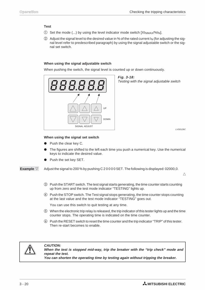
Test
Set the mode (...) by using the level indicator mode switch [XINMAX/%IN].
Adjust the signal level to the desired value in % of the rated current IN (for adjusting the sig-nal level refer to predescribed paragraph) by using the signal adjustable switch or the sig-nal set switch.
When using the signal adjustable switch
When pushing the switch, the signal level is counted up or down continuously.
When using the signal set switch
Push the clear key C.
The figures are shifted to the left each time you push a numerical key. Use the numericalkeys to indicate the desired value.
Push the set key SET.
Example Adjust the signal to 200 % by pushing C 2 0 0 0 0 SET. The following is displayed: 02000,0.
Push the START switch. The test signal starts generating, the time counter starts countingup from zero and the test mode indicator “TESTING” lights up.
Push the STOP switch. The Test signal stops generating, the time counter stops countingat the last value and the test mode indicator “TESTING” goes out.
You can use this switch to quit testing at any time.
When the electronic trip relay is released, the trip indicator of this tester lights up and the timecounter stops. The operating time is indicated on the time counter.
Push the RESET switch to reset the time counter and the trip indicator “TRIP” of this tester.Then re-start becomes to enable.
ECAUTION:When the test is stopped mid-way, trip the breaker with the “trip check” mode andrepeat the test.You can shorten the operating time by testing again without tripping the breaker.
3 - 20 MITSUBISHI ELECTRIC
Operation Checking the tripping characteristics
SIGNAL ADJUST
UP
DOWN
Fig. 3-18:Testing with the signal adjustable switch
LVS0126C
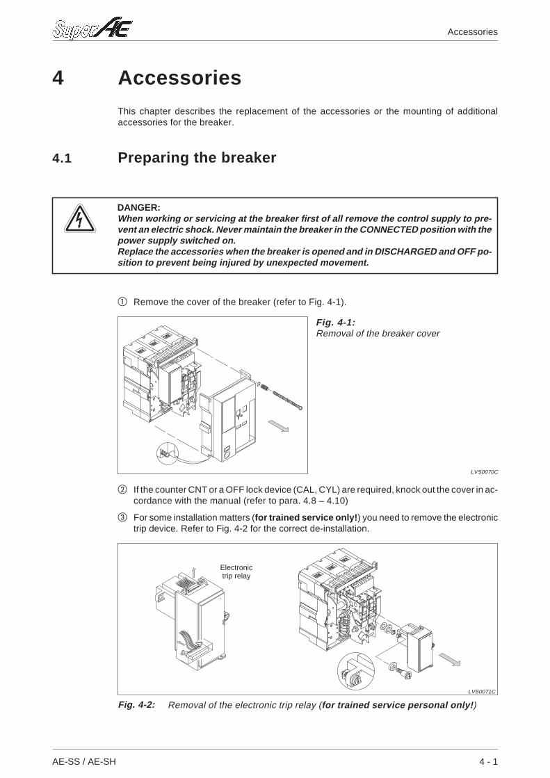
4 AccessoriesThis chapter describes the replacement of the accessories or the mounting of additionalaccessories for the breaker.
4.1 Preparing the breaker
PDANGER:When working or servicing at the breaker first of all remove the control supply to pre-vent an electric shock. Never maintain the breaker in the CONNECTED position with thepower supply switched on.Replace the accessories when the breaker is opened and in DISCHARGED and OFF po-sition to prevent being injured by unexpected movement.
Remove the cover of the breaker (refer to Fig. 4-1).
If the counter CNT or a OFF lock device (CAL, CYL) are required, knock out the cover in ac-cordance with the manual (refer to para. 4.8 – 4.10)
For some installation matters (for trained service only!) you need to remove the electronictrip device. Refer to Fig. 4-2 for the correct de-installation.
AE-SS / AE-SH 4 - 1
Accessories
Fig. 4-1:Removal of the breaker cover
LVS0070C
Fig. 4-2: Removal of the electronic trip relay (for trained service personal only!)
LVS0071C
Electronictrip relay
4.1.1 Overwiew
The following paragraphs contain information about the removal and installation of the follow-ing accessories:
AX Auxiliary switch refer to para 4.2
SHT Shunt trip device refer to para 4.3
CC Closing coil refer to para 4.4
UVT Undervoltage trip device refer to para 4.5
MD Motor charging device refer to para 4.6
CL Cell switch refer to para 4.7
CYL Cylinder lock refer to para 4.8
CAL Castell lock refer to para 4.9
CNT Counter refer to para 4.10
Furthermore, you will find information about various safety devicesand other accessories:
SST Safety shutter refer to para. 4.11
SBC Shorting b-contact refer to para. 4.12
MIP Mis-insertion preventor refer to para. 4.13
MI Mechanical interlock refer to para. 4.14
DI Door interlock refer to para. 4.15
TJ Test jumper refer to para. 4.16
ZCT External ZCT for load circuit refer to para. 4.17
BC-L Push-button cover refer to para. 4.18
FTA Front terminal adapter refer to para. 4.19
VTA Vertical terminal adapter refer to para. 4.20
4 - 2 MITSUBISHI ELECTRIC
Accessories Preparing the breaker
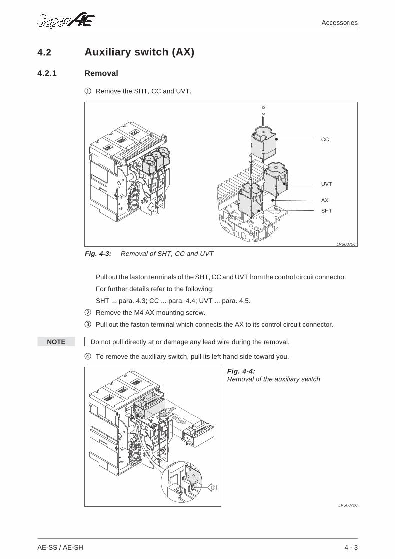
4.2 Auxiliary switch (AX)
4.2.1 Removal
Remove the SHT, CC and UVT.
Pull out the faston terminals of the SHT, CC and UVT from the control circuit connector.
For further details refer to the following:
SHT ... para. 4.3; CC ... para. 4.4; UVT ... para. 4.5.
Remove the M4 AX mounting screw.
Pull out the faston terminal which connects the AX to its control circuit connector.
NOTE Do not pull directly at or damage any lead wire during the removal.
To remove the auxiliary switch, pull its left hand side toward you.
AE-SS / AE-SH 4 - 3
Accessories
Fig. 4-3: Removal of SHT, CC and UVT
LVS0075C
CC
UVT
SHT
AX
Fig. 4-4:Removal of the auxiliary switch
LVS0072C
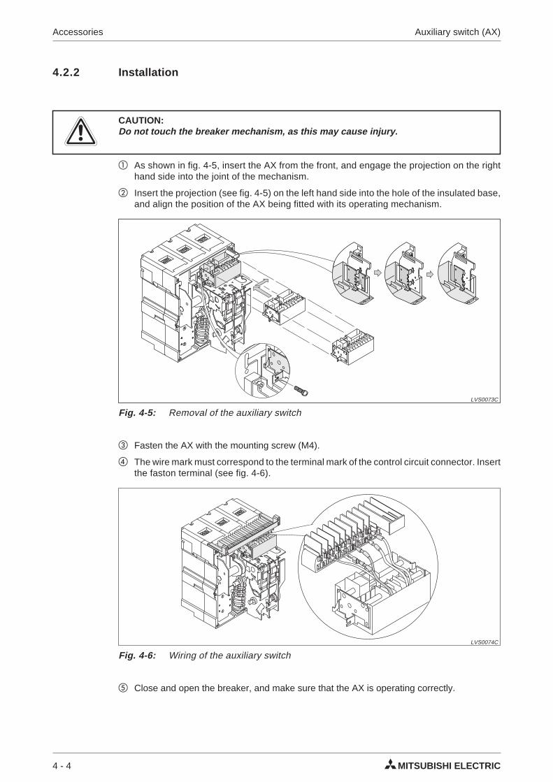
4.2.2 Installation
ECAUTION:Do not touch the breaker mechanism, as this may cause injury.
As shown in fig. 4-5, insert the AX from the front, and engage the projection on the righthand side into the joint of the mechanism.
Insert the projection (see fig. 4-5) on the left hand side into the hole of the insulated base,and align the position of the AX being fitted with its operating mechanism.
Fasten the AX with the mounting screw (M4).
The wire mark must correspond to the terminal mark of the control circuit connector. Insertthe faston terminal (see fig. 4-6).
Close and open the breaker, and make sure that the AX is operating correctly.
4 - 4 MITSUBISHI ELECTRIC
Accessories Auxiliary switch (AX)
Fig. 4-5: Removal of the auxiliary switch
LVS0073C
Fig. 4-6: Wiring of the auxiliary switch
LVS0074C
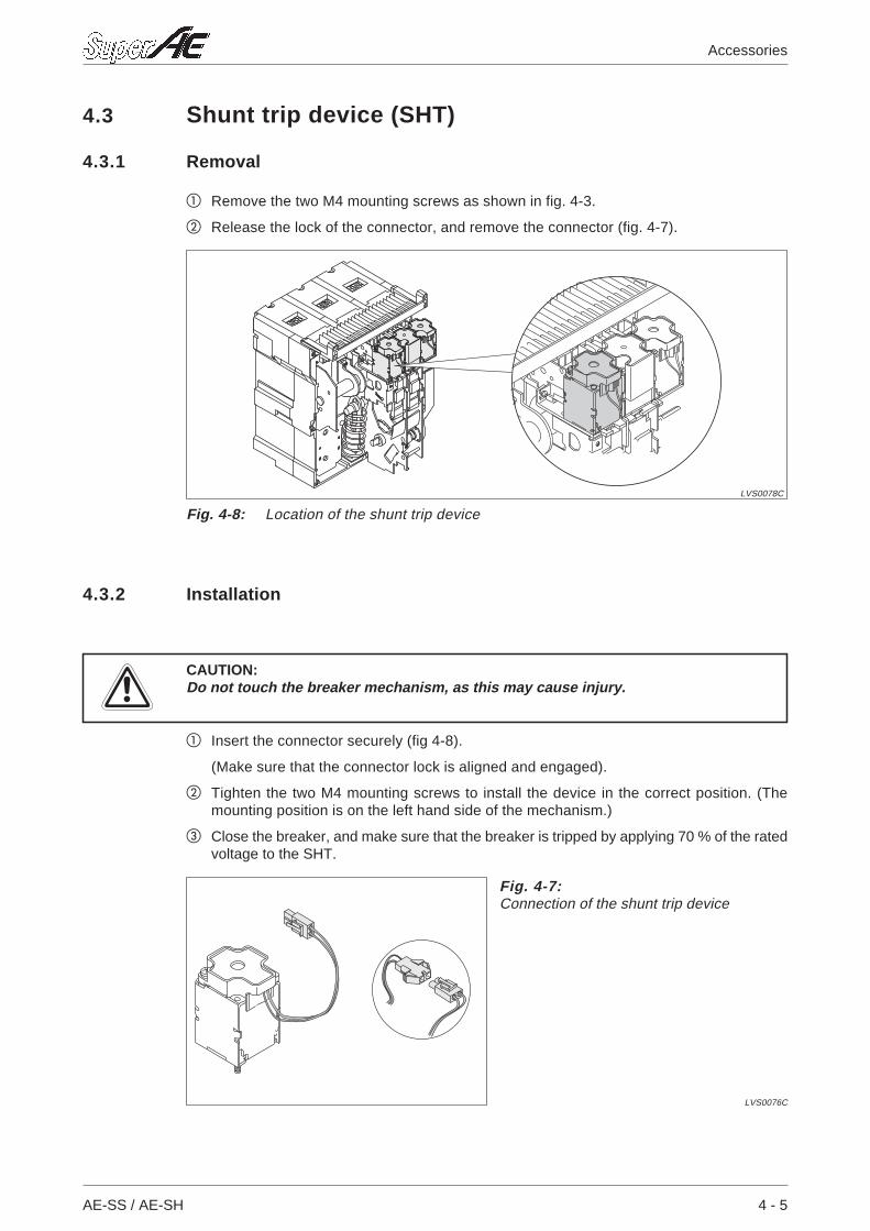
4.3 Shunt trip device (SHT)
4.3.1 Removal
Remove the two M4 mounting screws as shown in fig. 4-3.
Release the lock of the connector, and remove the connector (fig. 4-7).
4.3.2 Installation
ECAUTION:Do not touch the breaker mechanism, as this may cause injury.
Insert the connector securely (fig 4-8).
(Make sure that the connector lock is aligned and engaged).
Tighten the two M4 mounting screws to install the device in the correct position. (Themounting position is on the left hand side of the mechanism.)
Close the breaker, and make sure that the breaker is tripped by applying 70 % of the ratedvoltage to the SHT.
AE-SS / AE-SH 4 - 5
Accessories
Fig. 4-7:Connection of the shunt trip device
LVS0076C
Fig. 4-8: Location of the shunt trip device
LVS0078C
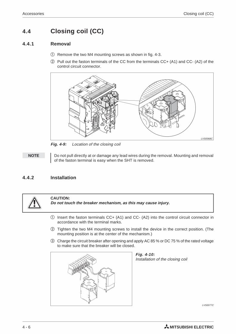
4.4 Closing coil (CC)
4.4.1 Removal
Remove the two M4 mounting screws as shown in fig. 4-3.
Pull out the faston terminals of the CC from the terminals CC+ (A1) and CC- (A2) of thecontrol circuit connector.
NOTE Do not pull directly at or damage any lead wires during the removal. Mounting and removalof the faston terminal is easy when the SHT is removed.
4.4.2 Installation
ECAUTION:Do not touch the breaker mechanism, as this may cause injury.
Insert the faston terminals CC+ (A1) and CC- (A2) into the control circuit connector inaccordance with the terminal marks.
Tighten the two M4 mounting screws to install the device in the correct position. (Themounting position is at the center of the mechanism.)
Charge the circuit breaker after opening and apply AC 85 % or DC 75 % of the rated voltageto make sure that the breaker will be closed.
4 - 6 MITSUBISHI ELECTRIC
Accessories Closing coil (CC)
Fig. 4-9: Location of the closing coil
LVS0068C
Fig. 4-10:Installation of the closing coil
LVS0077C
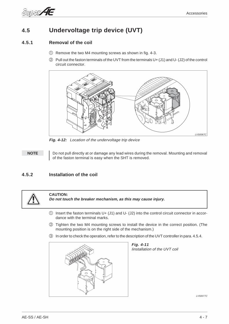
4.5 Undervoltage trip device (UVT)
4.5.1 Removal of the coil
Remove the two M4 mounting screws as shown in fig. 4-3.
Pull out the faston terminals of the UVT from the terminals U+ (J1) and U- (J2) of the controlcircuit connector.
NOTE Do not pull directly at or damage any lead wires during the removal. Mounting and removalof the faston terminal is easy when the SHT is removed.
4.5.2 Installation of the coil
ECAUTION:Do not touch the breaker mechanism, as this may cause injury.
Insert the faston terminals U+ (J1) and U- (J2) into the control circuit connector in accor-dance with the terminal marks.
Tighten the two M4 mounting screws to install the device in the correct position. (Themounting position is on the right side of the mechanism.)
In order to check the operation, refer to the description of the UVT controller in para. 4.5.4.
AE-SS / AE-SH 4 - 7
Accessories
Fig. 4-11Iinstallation of the UVT coil
LVS0077C
Fig. 4-12: Location of the undervoltage trip device
LVS0067C
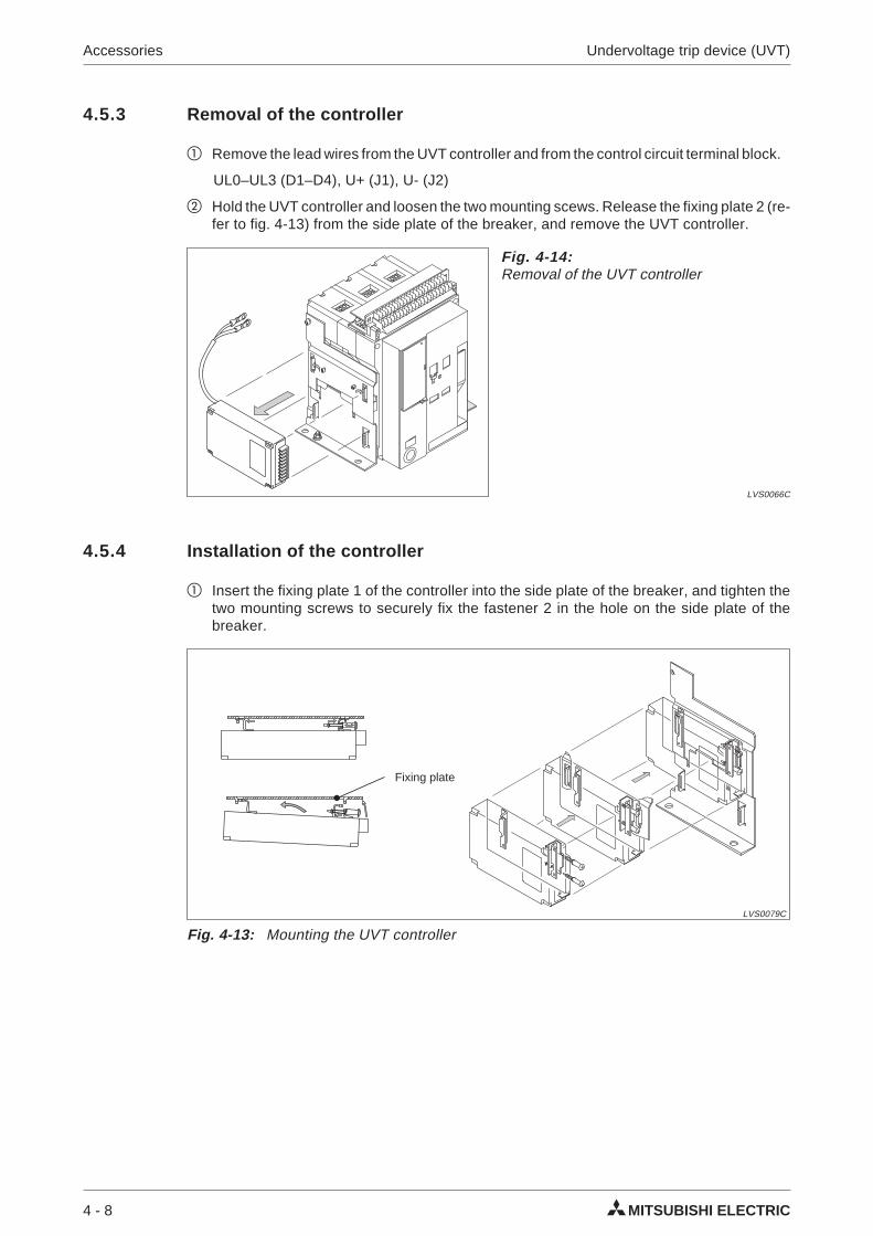
4.5.3 Removal of the controller
Remove the lead wires from the UVT controller and from the control circuit terminal block.
UL0–UL3 (D1–D4), U+ (J1), U- (J2)
Hold the UVT controller and loosen the two mounting scews. Release the fixing plate 2 (re-fer to fig. 4-13) from the side plate of the breaker, and remove the UVT controller.
4.5.4 Installation of the controller
Insert the fixing plate 1 of the controller into the side plate of the breaker, and tighten thetwo mounting screws to securely fix the fastener 2 in the hole on the side plate of thebreaker.
4 - 8 MITSUBISHI ELECTRIC
Accessories Undervoltage trip device (UVT)
Fig. 4-13: Mounting the UVT controller
LVS0079C
Fixing plate
Fig. 4-14:Removal of the UVT controller
LVS0066C
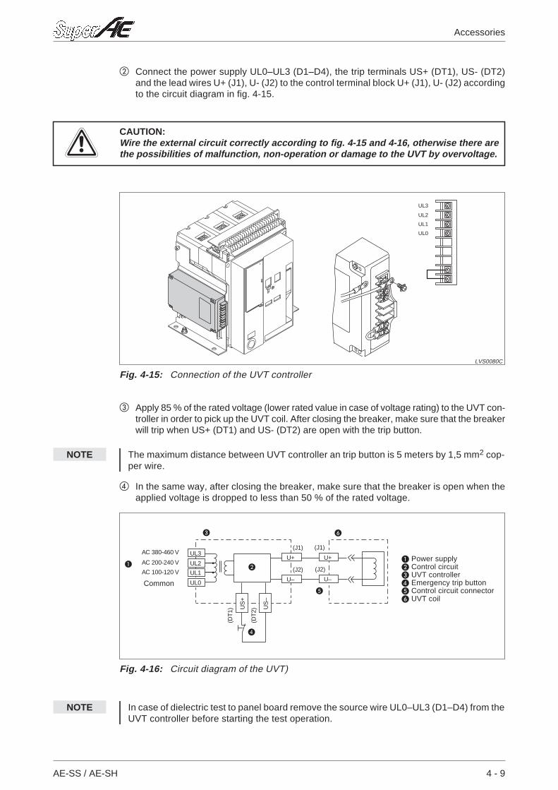
Connect the power supply UL0–UL3 (D1–D4), the trip terminals US+ (DT1), US- (DT2)and the lead wires U+ (J1), U- (J2) to the control terminal block U+ (J1), U- (J2) accordingto the circuit diagram in fig. 4-15.
ECAUTION:Wire the external circuit correctly according to fig. 4-15 and 4-16, otherwise there arethe possibilities of malfunction, non-operation or damage to the UVT by overvoltage.
Apply 85 % of the rated voltage (lower rated value in case of voltage rating) to the UVT con-troller in order to pick up the UVT coil. After closing the breaker, make sure that the breakerwill trip when US+ (DT1) and US- (DT2) are open with the trip button.
NOTE The maximum distance between UVT controller an trip button is 5 meters by 1,5 mm2 cop-per wire.
In the same way, after closing the breaker, make sure that the breaker is open when theapplied voltage is dropped to less than 50 % of the rated voltage.
NOTE In case of dielectric test to panel board remove the source wire UL0–UL3 (D1–D4) from theUVT controller before starting the test operation.
AE-SS / AE-SH 4 - 9
Accessories
UL3
UL2
UL1
UL0
Fig. 4-15: Connection of the UVT controller
LVS0080C
UL3
UL2
UL1
UL0
U+
U– U–
U+
US
+
US
–
(J1)
(DT
1)
(DT
2)
(J2)
(J1)
(J2)
AC 380-460 V
AC 200-240 V
AC 100-120 V
Summe
Fig. 4-16: Circuit diagram of the UVT)
Power supply Control circuit UVT controller Emergency trip button Control circuit connector UVT coil
Common
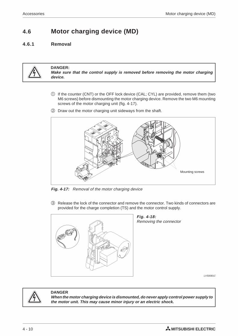
4.6 Motor charging device (MD)
4.6.1 Removal
PDANGER:Make sure that the control supply is removed before removing the motor chargingdevice.
If the counter (CNT) or the OFF lock device (CAL; CYL) are provided, remove them (twoM6 screws) before dismounting the motor charging device. Remove the two M6 mountingscrews of the motor charging unit (fig. 4-17).
Draw out the motor charging unit sideways from the shaft.
Release the lock of the connector and remove the connector. Two kinds of connectors areprovided for the charge completion (TS) and the motor control supply.
PDANGERWhen the motor charging device is dismounted, do never apply control power supply tothe motor unit. This may cause minor injury or an electric shock.
4 - 10 MITSUBISHI ELECTRIC
Accessories Motor charging device (MD)
Fig. 4-17: Removal of the motor charging device
Mounting screws
Fig. 4-18:Removing the connector
LVS0081C
4.6.2 Installation
ECAUTION:Do not touch the breaker mechanism, as this may cause injury.
If the CNT, CAL or CYL are provided, remove them (two M6 screws) before installing themotor charging unit.
Make sure that the driving cam shaft is latched to the projection of the motor frame (fig.4-20). If not so, turn the gear to latch the driving cam shaft with the projection.
Securely insert the connector to the motor charging unit. Make sure that the connector lockis engaged.
AE-SS / AE-SH 4 - 11
Accessories
Fig. 4-19:Remove any accessory around the motorcharging device before installing it
LVS0131C
Fig. 4-20:Take care of the correct cam shaft positionbefore mounting
LVS0084C
Projection Driving cam shaft
Fig. 4-21:Connect the motor wire
LVS0081C
Connector socket
Align the notch of the cam and the cam shaft, and insert the cam into the cam shaft asshown in fig. 4-22.
Install the motor charging unit with the two M6 mounting screws.
Apply 85 % of the rated voltage to the MD and make sure that motor charging is possible.After the charging is completed, check the output of the TS signal.
4 - 12 MITSUBISHI ELECTRIC
Accessories Motor charging device (MD)
Fig. 4-22: Mounting the motor charging device
LVS0085C
Mounting screws
Cam shaft
Cam
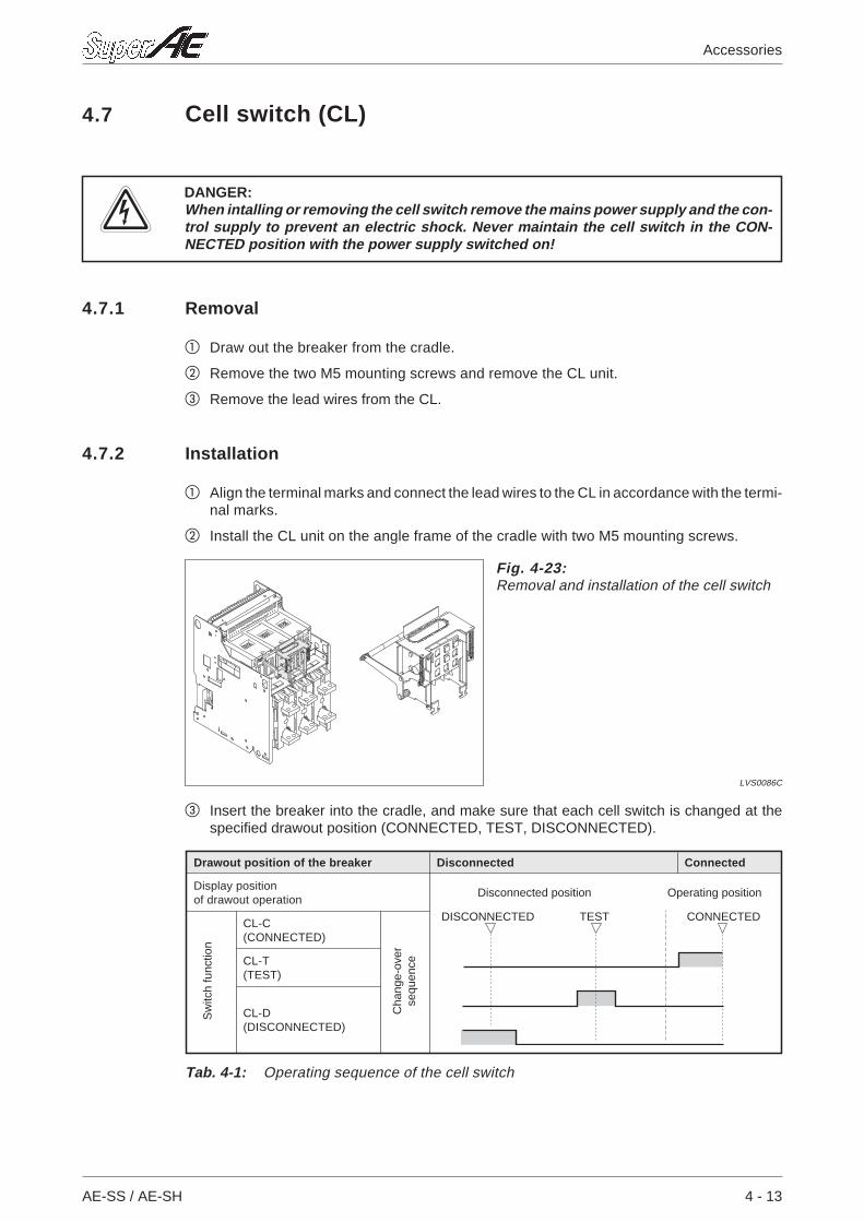
4.7 Cell switch (CL)
PDANGER:When intalling or removing the cell switch remove the mains power supply and the con-trol supply to prevent an electric shock. Never maintain the cell switch in the CON-NECTED position with the power supply switched on!
4.7.1 Removal
Draw out the breaker from the cradle.
Remove the two M5 mounting screws and remove the CL unit.
Remove the lead wires from the CL.
4.7.2 Installation
Align the terminal marks and connect the lead wires to the CL in accordance with the termi-nal marks.
Install the CL unit on the angle frame of the cradle with two M5 mounting screws.
Insert the breaker into the cradle, and make sure that each cell switch is changed at thespecified drawout position (CONNECTED, TEST, DISCONNECTED).
AE-SS / AE-SH 4 - 13
Accessories
Fig. 4-23:Removal and installation of the cell switch
LVS0086C
Drawout position of the breaker Disconnected Connected
Display positionof drawout operation
CL-C(CONNECTED)
CL-T(TEST)
CL-D(DISCONNECTED)
Tab. 4-1: Operating sequence of the cell switch
Disconnected position Operating position
DISCONNECTED TEST CONNECTED
Sw
itch
func
tion
Cha
nge-
over
sequ
ence
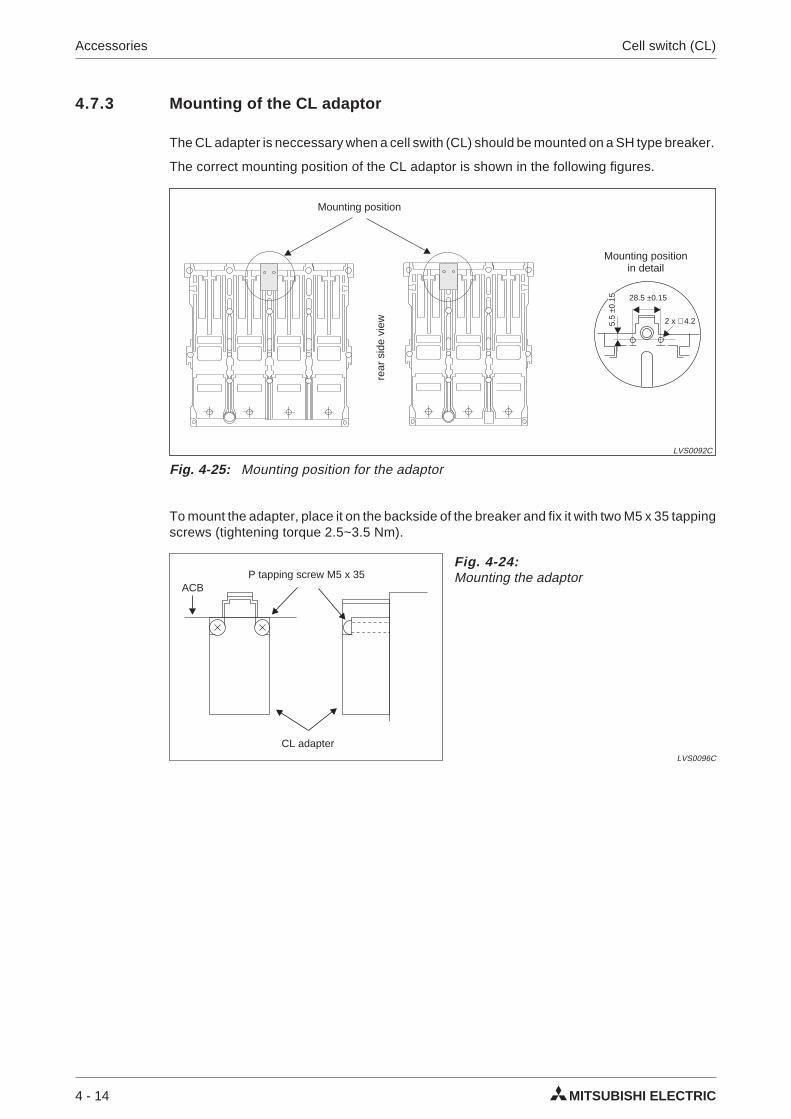
4.7.3 Mounting of the CL adaptor
The CL adapter is neccessary when a cell swith (CL) should be mounted on a SH type breaker.
The correct mounting position of the CL adaptor is shown in the following figures.
To mount the adapter, place it on the backside of the breaker and fix it with two M5 x 35 tappingscrews (tightening torque 2.5~3.5 Nm).
4 - 14 MITSUBISHI ELECTRIC
Accessories Cell switch (CL)
Fig. 4-24:Mounting the adaptor
LVS0096C
P tapping screw M5 x 35
CL adapter
ACB
Fig. 4-25: Mounting position for the adaptor
LVS0092C
Mounting position
Mounting positionin detail
28.5 ±0.15
2 x ∅ 4.25.5
±0.1
5
rear
side
view
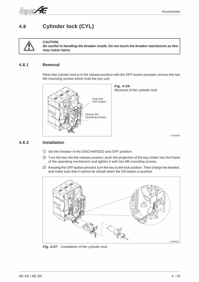
4.8 Cylinder lock (CYL)
ECAUTION:Be careful in handling the breaker inside. Do not touch the breaker mechanism as thismay cuase injury.
4.8.1 Removal
When the cylinder lock is in the release position with the OFF button pressed, remove the twoM6 mounting screws which hold the key unit.
4.8.2 Installation
Set the breaker in the DISCHARGED and OFF position.
Turn the key into the release position, push the projection of the key holder into the frameof the operating mechanism and tighten it with two M6 mounting screws.
Keeping the OFF button pressed, turn the key to the lock position. Then charge the breaker,and make sure that it cannot be closed when the ON button is pushed.
AE-SS / AE-SH 4 - 15
Accessories
Fig. 4-26:Removal of the cylinder lock
LVS0090C
Detach themounting screws
Push theOFF button
Fig. 4-27: Installation of the cylinder lock
LVS0091C
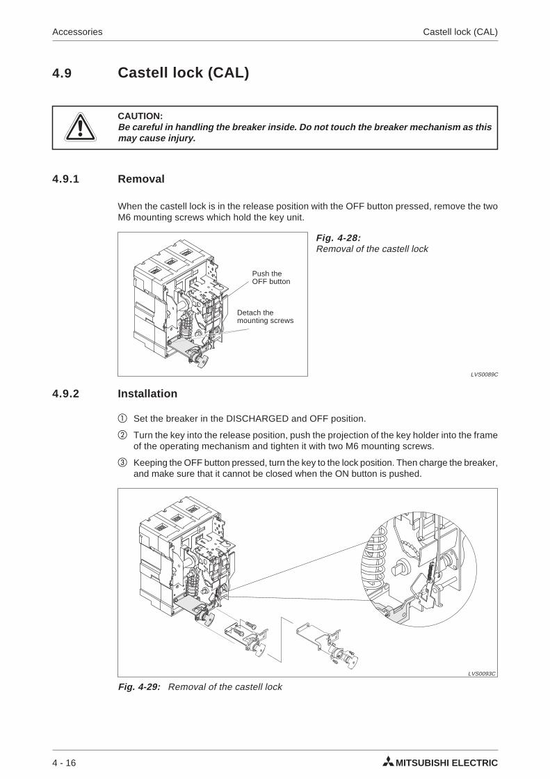
4.9 Castell lock (CAL)
ECAUTION:Be careful in handling the breaker inside. Do not touch the breaker mechanism as thismay cause injury.
4.9.1 Removal
When the castell lock is in the release position with the OFF button pressed, remove the twoM6 mounting screws which hold the key unit.
4.9.2 Installation
Set the breaker in the DISCHARGED and OFF position.
Turn the key into the release position, push the projection of the key holder into the frameof the operating mechanism and tighten it with two M6 mounting screws.
Keeping the OFF button pressed, turn the key to the lock position. Then charge the breaker,and make sure that it cannot be closed when the ON button is pushed.
4 - 16 MITSUBISHI ELECTRIC
Accessories Castell lock (CAL)
Fig. 4-28:Removal of the castell lock
LVS0089C
Detach themounting screws
Push theOFF button
Fig. 4-29: Removal of the castell lock
LVS0093C
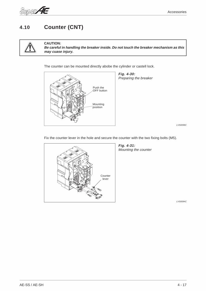
4.10 Counter (CNT)
ECAUTION:Be careful in handling the breaker inside. Do not touch the breaker mechanism as thismay cuase injury.
The counter can be mounted directly abobe the cylinder or castell lock.
Fix the counter lever in the hole and secure the counter with the two fixing bolts (M5).
AE-SS / AE-SH 4 - 17
Accessories
Fig. 4-30:Preparing the breaker
LVS0099C
Mountingposition
Push theOFF button
Fig. 4-31:Mounting the counter
LVS0094C
Counterlever
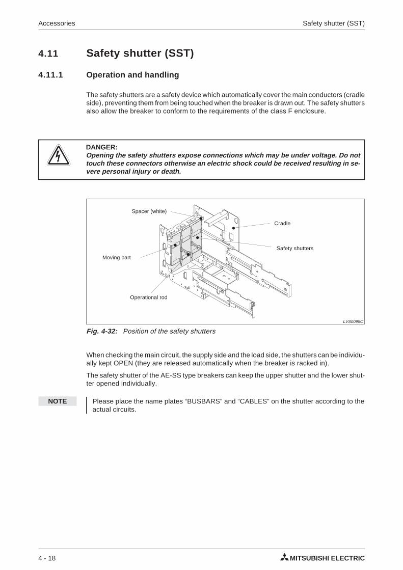
4.11 Safety shutter (SST)
4.11.1 Operation and handling
The safety shutters are a safety device which automatically cover the main conductors (cradleside), preventing them from being touched when the breaker is drawn out. The safety shuttersalso allow the breaker to conform to the requirements of the class F enclosure.
PDANGER:Opening the safety shutters expose connections which may be under voltage. Do nottouch these connectors otherwise an electric shock could be received resulting in se-vere personal injury or death.
When checking the main circuit, the supply side and the load side, the shutters can be individu-ally kept OPEN (they are released automatically when the breaker is racked in).
The safety shutter of the AE-SS type breakers can keep the upper shutter and the lower shut-ter opened individually.
NOTE Please place the name plates “BUSBARS” and “CABLES” on the shutter according to theactual circuits.
4 - 18 MITSUBISHI ELECTRIC
Accessories Safety shutter (SST)
Fig. 4-32: Position of the safety shutters
LVS0095C
Moving part
Operational rod
Safety shutters
Cradle
Spacer (white)
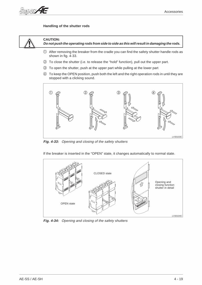
Handling of the shutter rods
ECAUTION:Do not push the operating rods from side to side as this will result in damaging the rods.
After removing the breaker from the cradle you can find the safety shutter handle rods asshown in fig. 4-33.
To close the shutter (i.e. to release the “hold” function), pull out the upper part.
To open the shutter, push at the upper part while pulling at the lower part
To keep the OPEN position, push both the left and the right operation rods in until they arestopped with a clicking sound.
If the breaker is inserted in the “OPEN” state, it changes automatically to normal state.
AE-SS / AE-SH 4 - 19
Accessories
Fig. 4-33: Opening and closing of the safety shutters
LVS0103C
Fig. 4-34: Opening and closing of the safety shutters
LVS0104C
CLOSED state
OPEN state
Opening andclosing functionshutter in detail
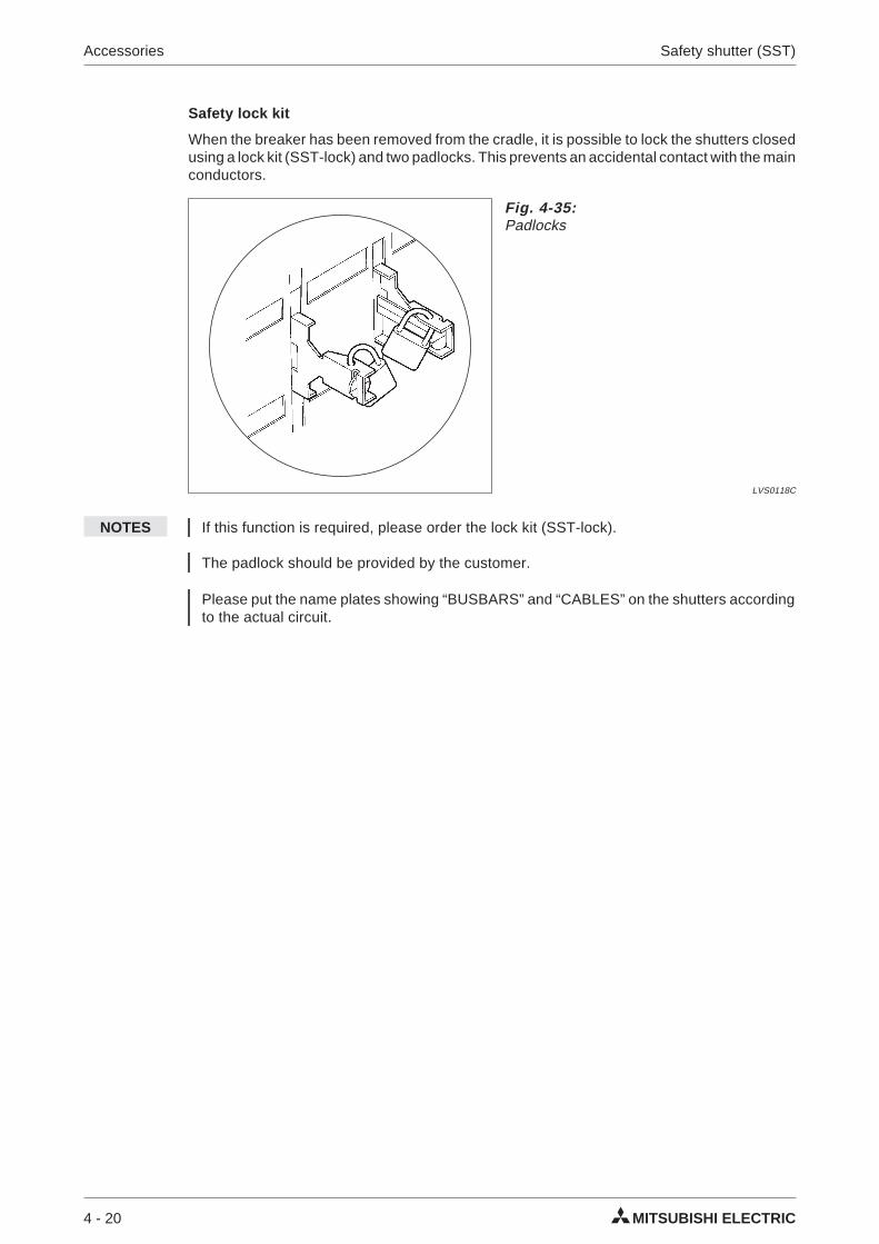
Safety lock kit
When the breaker has been removed from the cradle, it is possible to lock the shutters closedusing a lock kit (SST-lock) and two padlocks. This prevents an accidental contact with the mainconductors.
NOTES If this function is required, please order the lock kit (SST-lock).
The padlock should be provided by the customer.
Please put the name plates showing “BUSBARS” and “CABLES” on the shutters accordingto the actual circuit.
4 - 20 MITSUBISHI ELECTRIC
Accessories Safety shutter (SST)
Fig. 4-35:Padlocks
LVS0118C
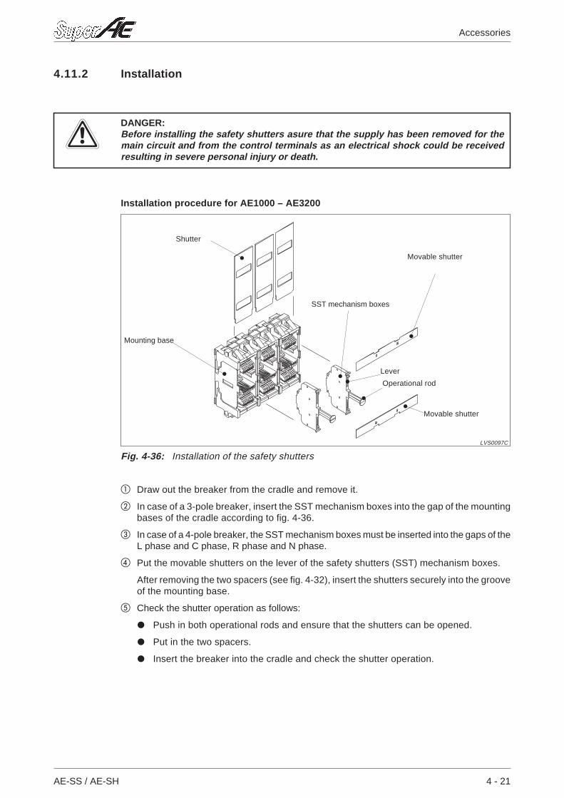
4.11.2 Installation
EDANGER:Before installing the safety shutters asure that the supply has been removed for themain circuit and from the control terminals as an electrical shock could be receivedresulting in severe personal injury or death.
Installation procedure for AE1000 – AE3200
Draw out the breaker from the cradle and remove it.
In case of a 3-pole breaker, insert the SST mechanism boxes into the gap of the mountingbases of the cradle according to fig. 4-36.
In case of a 4-pole breaker, the SST mechanism boxes must be inserted into the gaps of theL phase and C phase, R phase and N phase.
Put the movable shutters on the lever of the safety shutters (SST) mechanism boxes.
After removing the two spacers (see fig. 4-32), insert the shutters securely into the grooveof the mounting base.
Check the shutter operation as follows:
Push in both operational rods and ensure that the shutters can be opened.
Put in the two spacers.
Insert the breaker into the cradle and check the shutter operation.
AE-SS / AE-SH 4 - 21
Accessories
Fig. 4-36: Installation of the safety shutters
LVS0097C
Lever
Mounting base
SST mechanism boxes
Shutter
Movable shutter
Operational rod
Movable shutter
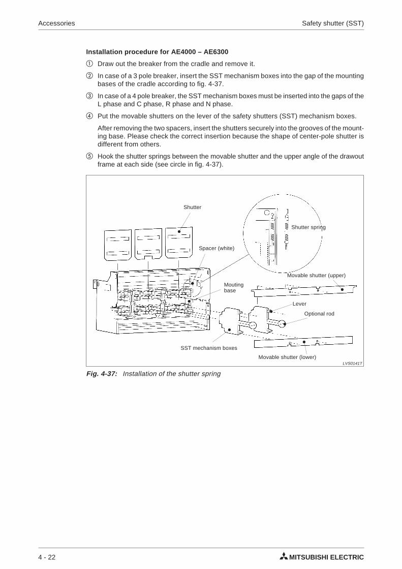
Installation procedure for AE4000 – AE6300
Draw out the breaker from the cradle and remove it.
In case of a 3 pole breaker, insert the SST mechanism boxes into the gap of the mountingbases of the cradle according to fig. 4-37.
In case of a 4 pole breaker, the SST mechanism boxes must be inserted into the gaps of theL phase and C phase, R phase and N phase.
Put the movable shutters on the lever of the safety shutters (SST) mechanism boxes.
After removing the two spacers, insert the shutters securely into the grooves of the mount-ing base. Please check the correct insertion because the shape of center-pole shutter isdifferent from others.
Hook the shutter springs between the movable shutter and the upper angle of the drawoutframe at each side (see circle in fig. 4-37).
4 - 22 MITSUBISHI ELECTRIC
Accessories Safety shutter (SST)
Fig. 4-37: Installation of the shutter spring
LVS0141T
Spacer (white)
Shutter
Optional rod
Movable shutter (upper)
Shutter spring
SST mechanism boxes
Lever
Movable shutter (lower)
Moutingbase
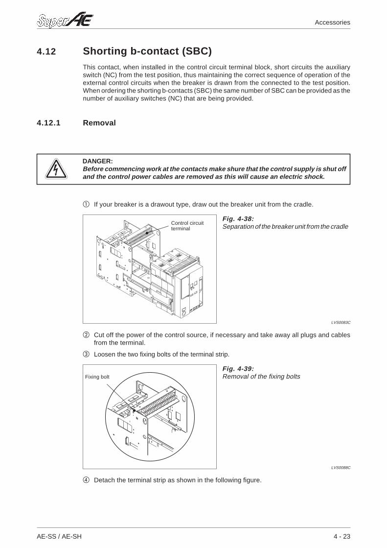
4.12 Shorting b-contact (SBC)This contact, when installed in the control circuit terminal block, short circuits the auxiliaryswitch (NC) from the test position, thus maintaining the correct sequence of operation of theexternal control circuits when the breaker is drawn from the connected to the test position.When ordering the shorting b-contacts (SBC) the same number of SBC can be provided as thenumber of auxiliary switches (NC) that are being provided.
4.12.1 Removal
PDANGER:Before commencing work at the contacts make shure that the control supply is shut offand the control power cables are removed as this will cause an electric shock.
If your breaker is a drawout type, draw out the breaker unit from the cradle.
Cut off the power of the control source, if necessary and take away all plugs and cablesfrom the terminal.
Loosen the two fixing bolts of the terminal strip.
Detach the terminal strip as shown in the following figure.
AE-SS / AE-SH 4 - 23
Accessories
Fig. 4-38:Separation of the breaker unit from the cradle
LVS0083C
Control circuitterminal
Fig. 4-39:Removal of the fixing bolts
LVS0088C
Fixing bolt
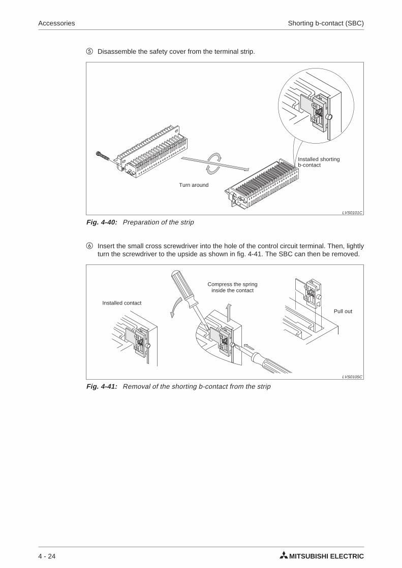
Disassemble the safety cover from the terminal strip.
Insert the small cross screwdriver into the hole of the control circuit terminal. Then, lightlyturn the screwdriver to the upside as shown in fig. 4-41. The SBC can then be removed.
4 - 24 MITSUBISHI ELECTRIC
Accessories Shorting b-contact (SBC)
Fig. 4-40: Preparation of the strip
LVS0101C
Installed shortingb-contact
Turn around
Fig. 4-41: Removal of the shorting b-contact from the strip
LVS0105C
Compress the springinside the contact
Pull out
Installed contact
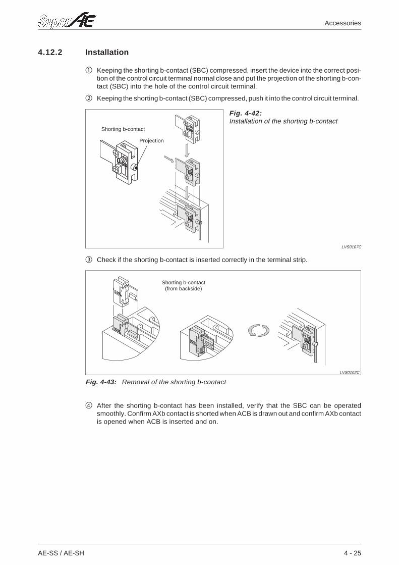
4.12.2 Installation
Keeping the shorting b-contact (SBC) compressed, insert the device into the correct posi-tion of the control circuit terminal normal close and put the projection of the shorting b-con-tact (SBC) into the hole of the control circuit terminal.
Keeping the shorting b-contact (SBC) compressed, push it into the control circuit terminal.
Check if the shorting b-contact is inserted correctly in the terminal strip.
After the shorting b-contact has been installed, verify that the SBC can be operatedsmoothly. Confirm AXb contact is shorted when ACB is drawn out and confirm AXb contactis opened when ACB is inserted and on.
AE-SS / AE-SH 4 - 25
Accessories
Fig. 4-42:Installation of the shorting b-contact
LVS0107C
Shorting b-contact
Projection
Fig. 4-43: Removal of the shorting b-contact
LVS0102C
Shorting b-contact(from backside)
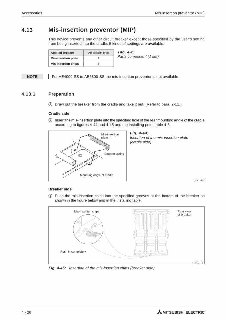
4.13 Mis-insertion preventor (MIP)This device prevents any other circuit breaker except those specified by the user’s settingfrom being inserted into the cradle. 5 kinds of settings are available.
NOTE For AE4000-SS to AE6300-SS the mis-insertion preventor is not available.
4.13.1 Preparation
Draw out the breaker from the cradle and take it out. (Refer to para. 2-11.)
Cradle side
Insert the mis-insertion plate into the specified hole of the rear mounting angle of the cradleaccording to figures 4-44 and 4-45 and the installing point table 4-3.
Breaker side
Push the mis-insertion chips into the specified grooves at the bottom of the breaker asshown in the figure below and in the installing table.
4 - 26 MITSUBISHI ELECTRIC
Accessories Mis-insertion preventor (MIP)
Applied breaker AE-SS/SH type
Mis-insertion plate 1
Mis-insertion chips 5
Tab. 4-2:Parts component (1 set)
Fig. 4-44:Insertion of the mis-insertion plate(cradle side)
LVS0108C
Mis-insertionplate
Stopper spring
Mounting angle of cradle
Fig. 4-45: Insertion of the mis-insertion chips (breaker side)
LVS0110C
Push in completely
Rear viewof breaker
Mis-insertion chips
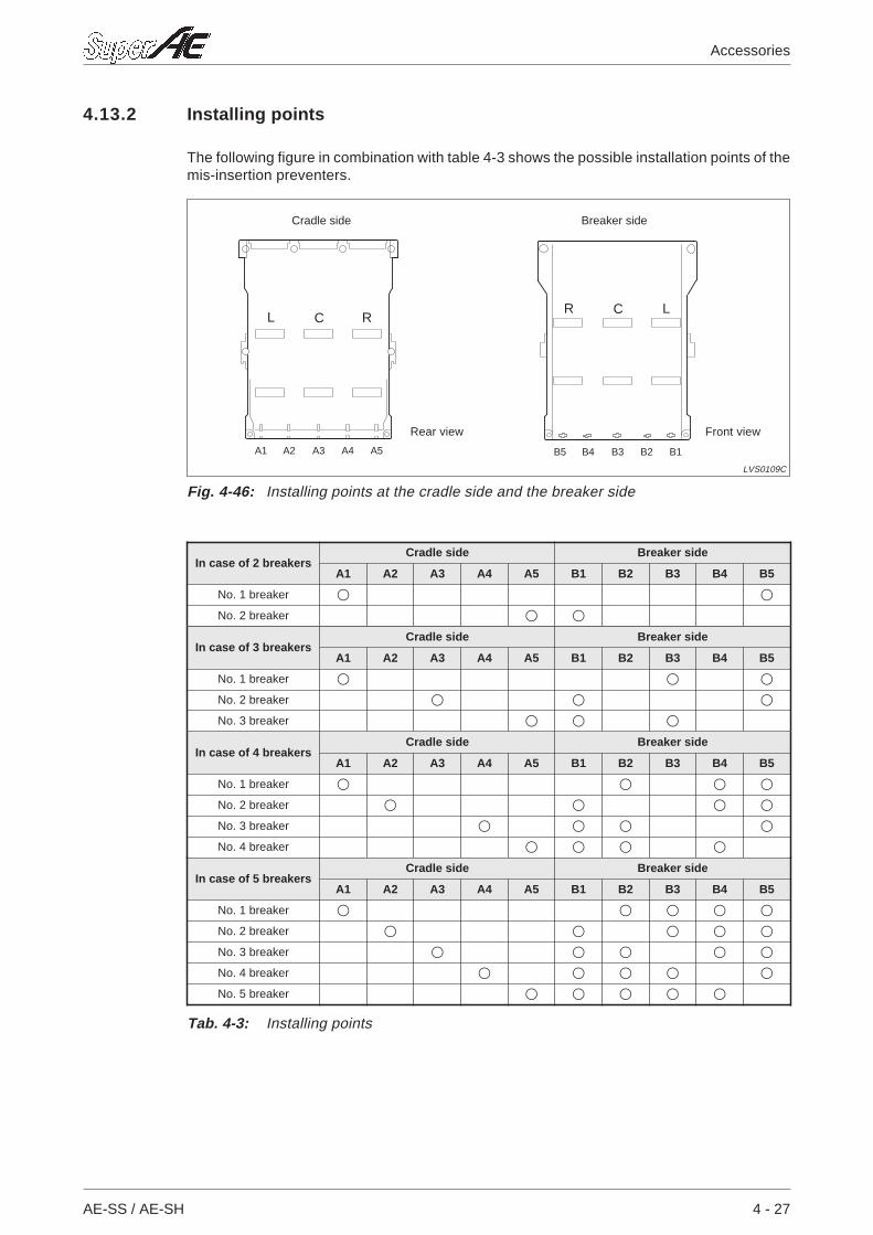
4.13.2 Installing points
The following figure in combination with table 4-3 shows the possible installation points of themis-insertion preventers.
AE-SS / AE-SH 4 - 27
Accessories
A1 B5A2 B4A3 B3A4 B2A5 B1
RCLR C L
Fig. 4-46: Installing points at the cradle side and the breaker side
LVS0109C
Front viewRear view
Cradle side Breaker side
In case of 2 breakersCradle side Breaker side
A1 A2 A3 A4 A5 B1 B2 B3 B4 B5
No. 1 breaker
No. 2 breaker
In case of 3 breakersCradle side Breaker side
A1 A2 A3 A4 A5 B1 B2 B3 B4 B5
No. 1 breaker
No. 2 breaker
No. 3 breaker
In case of 4 breakersCradle side Breaker side
A1 A2 A3 A4 A5 B1 B2 B3 B4 B5
No. 1 breaker
No. 2 breaker
No. 3 breaker
No. 4 breaker
In case of 5 breakersCradle side Breaker side
A1 A2 A3 A4 A5 B1 B2 B3 B4 B5
No. 1 breaker
No. 2 breaker
No. 3 breaker
No. 4 breaker
No. 5 breaker
Tab. 4-3: Installing points
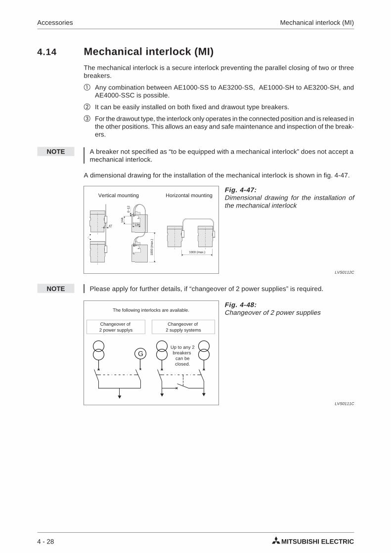
4.14 Mechanical interlock (MI)The mechanical interlock is a secure interlock preventing the parallel closing of two or threebreakers.
Any combination between AE1000-SS to AE3200-SS, AE1000-SH to AE3200-SH, andAE4000-SSC is possible.
It can be easily installed on both fixed and drawout type breakers.
For the drawout type, the interlock only operates in the connected position and is released inthe other positions. This allows an easy and safe maintenance and inspection of the break-ers.
NOTE A breaker not specified as “to be equipped with a mechanical interlock” does not accept amechanical interlock.
A dimensional drawing for the installation of the mechanical interlock is shown in fig. 4-47.
NOTE Please apply for further details, if “changeover of 2 power supplies” is required.
4 - 28 MITSUBISHI ELECTRIC
Accessories Mechanical interlock (MI)
47 134
144
0~12
1000
(max
.)
1000 (max.)
Fig. 4-47:Dimensional drawing for the installation ofthe mechanical interlock
LVS0112C
Vertical mounting Horizontal mounting
G
Fig. 4-48:Changeover of 2 power supplies
LVS0111C
The following interlocks are available.
Up to any 2breakers
can beclosed.
Changeover of2 power supplys
Changeover of2 supply systems
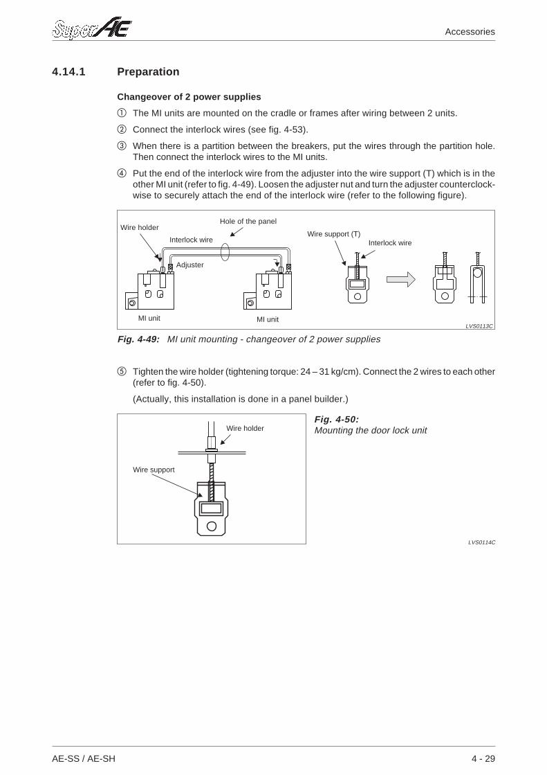
4.14.1 Preparation
Changeover of 2 power supplies
The MI units are mounted on the cradle or frames after wiring between 2 units.
Connect the interlock wires (see fig. 4-53).
When there is a partition between the breakers, put the wires through the partition hole.Then connect the interlock wires to the MI units.
Put the end of the interlock wire from the adjuster into the wire support (T) which is in theother MI unit (refer to fig. 4-49). Loosen the adjuster nut and turn the adjuster counterclock-wise to securely attach the end of the interlock wire (refer to the following figure).
Tighten the wire holder (tightening torque: 24 – 31 kg/cm). Connect the 2 wires to each other(refer to fig. 4-50).
(Actually, this installation is done in a panel builder.)
AE-SS / AE-SH 4 - 29
Accessories
Fig. 4-49: MI unit mounting - changeover of 2 power supplies
LVS0113CMI unit MI unit
Wire holderWire support (T)
Interlock wire Interlock wire
Adjuster
Hole of the panel
Fig. 4-50:Mounting the door lock unit
LVS0114C
Wire holder
Wire support
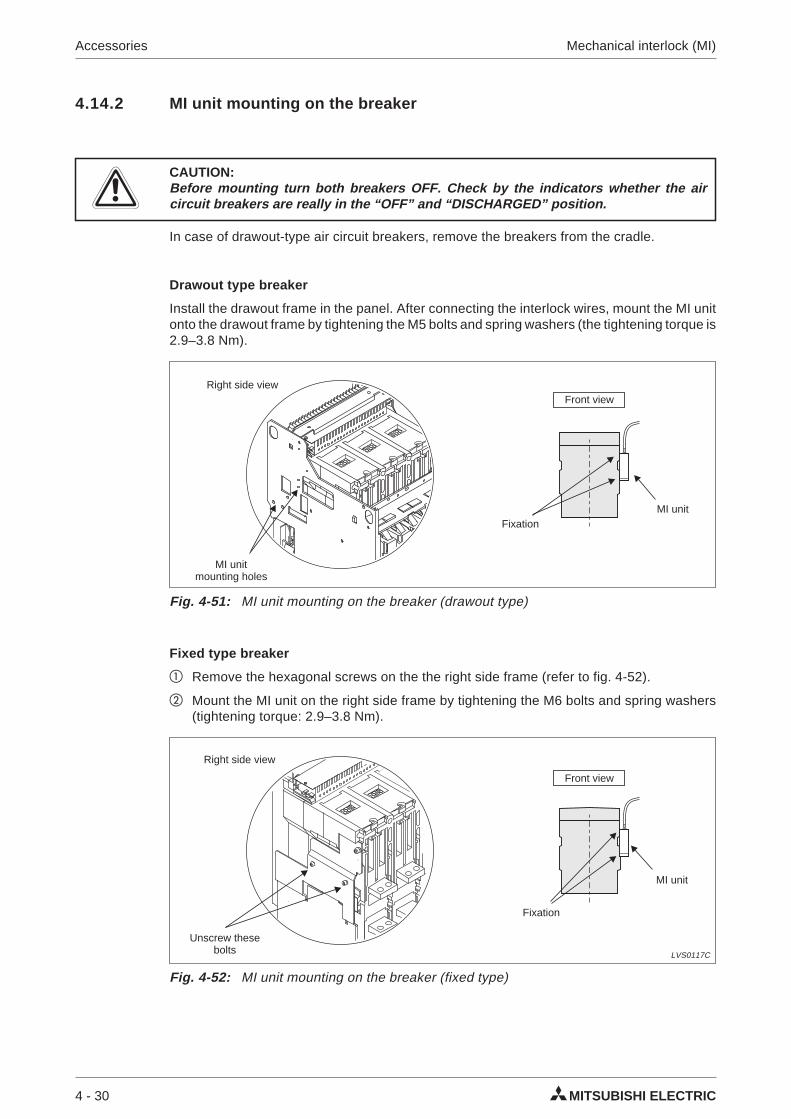
4.14.2 MI unit mounting on the breaker
ECAUTION:Before mounting turn both breakers OFF. Check by the indicators whether the aircircuit breakers are really in the “OFF” and “DISCHARGED” position.
In case of drawout-type air circuit breakers, remove the breakers from the cradle.
Drawout type breaker
Install the drawout frame in the panel. After connecting the interlock wires, mount the MI unitonto the drawout frame by tightening the M5 bolts and spring washers (the tightening torque is2.9–3.8 Nm).
Fixed type breaker
Remove the hexagonal screws on the the right side frame (refer to fig. 4-52).
Mount the MI unit on the right side frame by tightening the M6 bolts and spring washers(tightening torque: 2.9–3.8 Nm).
4 - 30 MITSUBISHI ELECTRIC
Accessories Mechanical interlock (MI)
Fig. 4-51: MI unit mounting on the breaker (drawout type)
Right side view
MI unitmounting holes
Front view
MI unitFixation
Fig. 4-52: MI unit mounting on the breaker (fixed type)
LVS0117C
MI unit
Unscrew thesebolts
Right side view
Fixation
Front view
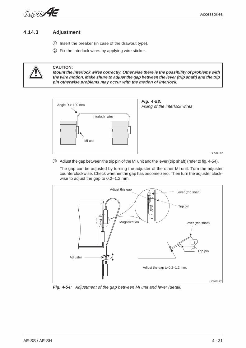
4.14.3 Adjustment
Insert the breaker (in case of the drawout type).
Fix the interlock wires by applying wire sticker.
ECAUTION:Mount the interlock wires correctly. Otherwise there is the possibility of problems withthe wire motion. Make shure to adjust the gap between the lever (trip shaft) and the trippin otherwise problems may occur with the motion of interlock.
Adjust the gap between the trip pin of the MI unit and the lever (trip shaft) (refer to fig. 4-54).
The gap can be adjusted by turning the adjuster of the other MI unit. Turn the adjustercounterclockwise. Check whether the gap has become zero. Then turn the adjuster clock-wise to adjust the gap to 0.2–1.2 mm.
AE-SS / AE-SH 4 - 31
Accessories
Fig. 4-53:Fixing of the interlock wires
LVS0115C
MI unit
Interlock wire
Angle R > 100 mm
Fig. 4-54: Adjustment of the gap between MI unit and lever (detail)
LVS0119C
Magnification
Trip pin
Adjust the gap to 0.2–1.2 mm.
Trip pin
Lever (trip shaft)
Adjuster
Lever (trip shaft)Adjust this gap
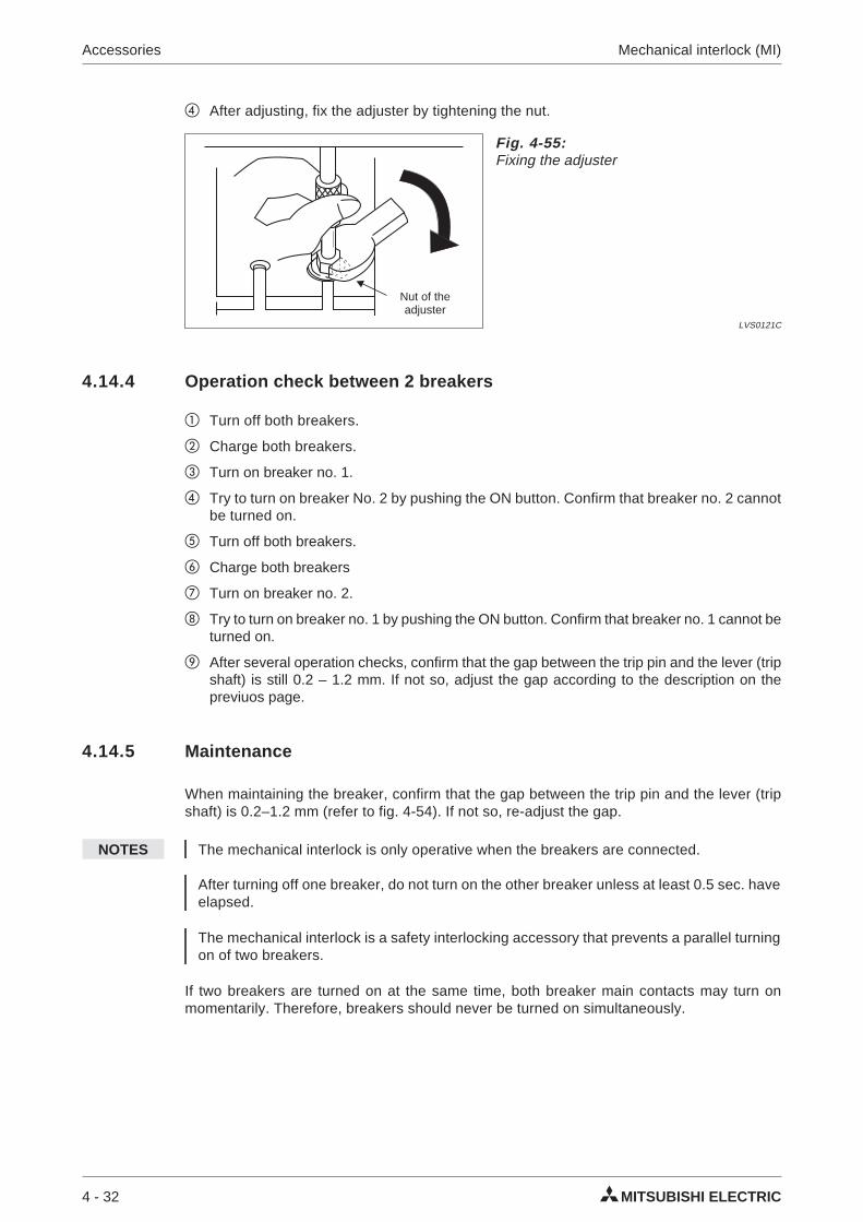
After adjusting, fix the adjuster by tightening the nut.
4.14.4 Operation check between 2 breakers
Turn off both breakers.
Charge both breakers.
Turn on breaker no. 1.
Try to turn on breaker No. 2 by pushing the ON button. Confirm that breaker no. 2 cannotbe turned on.
Turn off both breakers.
Charge both breakers
Turn on breaker no. 2.
Try to turn on breaker no. 1 by pushing the ON button. Confirm that breaker no. 1 cannot beturned on.
After several operation checks, confirm that the gap between the trip pin and the lever (tripshaft) is still 0.2 – 1.2 mm. If not so, adjust the gap according to the description on thepreviuos page.
4.14.5 Maintenance
When maintaining the breaker, confirm that the gap between the trip pin and the lever (tripshaft) is 0.2–1.2 mm (refer to fig. 4-54). If not so, re-adjust the gap.
NOTES The mechanical interlock is only operative when the breakers are connected.
After turning off one breaker, do not turn on the other breaker unless at least 0.5 sec. haveelapsed.
The mechanical interlock is a safety interlocking accessory that prevents a parallel turningon of two breakers.
If two breakers are turned on at the same time, both breaker main contacts may turn onmomentarily. Therefore, breakers should never be turned on simultaneously.
4 - 32 MITSUBISHI ELECTRIC
Accessories Mechanical interlock (MI)
Fig. 4-55:Fixing the adjuster
LVS0121C
Nut of theadjuster
4.15 Door interlock (DI)The door interlock is a safety device that allows the panel door to open only when the breakeris turned OFF: This interlock system features an interlock wire which interlocks the DI unit onthe breaker’s side with the door lock unit. Thus, the breaker can be installed in any positionwithin a specified area. Follow the instructions given below when installing this device.
4.15.1 DI unit mounting (installation of DI unit)
ECAUTION:Before mounting turn the breaker OFF. Check by the indicator whether the air circuitbreaker is in the “OFF” and “DISCHARGED” position.
In case of drawout-type air circuit breakers, remove the breakers from the cradle.
Drawout type breaker
Install the drawout frame in the panel. After connecting the interlock wires, mount the DI unitonto the drawout frame by tightening the M5 bolts and spring washers (the tightening torque is2.9–3.8 Nm).
AE-SS / AE-SH 4 - 33
Accessories
Fig. 4-56: DI unit mounting on the breaker (drawout type)LVS0116C
Right side view
DI unitmounting holes
Front view
DI unitFixation
Fixed type breaker
Remove the hexagonal screws on the the right side frame (refer to fig. 4-57).
Mount the DI unit on the right side frame by tightening the M6 bolts and spring washers(tightening torque: 2.9–3.8 Nm).
4 - 34 MITSUBISHI ELECTRIC
Accessories Door interlock (DI)
Fig. 4-57: DI unit mounting on the breaker (fixed type)
LVS0117C
DI unit
Unscrew thesebolts
Right side view
Fixation
Front view
4.15.2 Door lock unit mounting
Mount the door lock unit at a suitable place for door locking in the panel by using 2 M5 x 14screws (refer to fig. 4-58 as an example).
NOTE As the door hook is not included in this accessory, it has to be provided by the customer.
AE-SS / AE-SH 4 - 35
Accessories
106
56,5
22,5
20
3
1~3 mm
Fig. 4-58: Example for mounting the door lock
LVS0122C
View A
Mounting frame
Door lock unit
Door hook1–3 mm
Panel doorPanel enclosure
Door openDoor hook (thickness: 3 mm)
M5 x 14SW-PW-P
screw
120
70
62
5,5
53,5
5,5
16 1624 36,5 16 1624
36,5
91
Fig. 4-59: Dimensions for unit mounting on the surface (in mm)
LVS0123C
Mounting on the vertical surfaceRemove the mounting frame
Mounting on the horizontal frame
Put the end of the interlock wire from the adjuster into the wire support which is situated inthe door lock unit.
As the door lock unit has 2 wire supports, any connection (vertical or horizontal) can bechosen (see fig. 4-60).
Loosen the adjuster nut and turn the adjuster counterclockwise to securely attach the end ofthe interlock wire.
Tighten the wire holder (tightening torque: 2.4 – 3.1 Nm; refer to fig. 4-61).
4 - 36 MITSUBISHI ELECTRIC
Accessories Door interlock (DI)
~
~
Fig. 4-60: Installation of the interlock wire
LVS0127C
Put the end of the interlockwire into the wire support
Vertical connection
Wire support (horizontal)
Wire support(vertical)
Horizontalconnection
~
~ Fig. 4-61:Tightening of the wire holder
LVS0124C
Wireholder
Wire holder
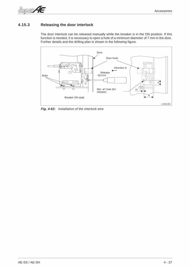
4.15.3 Releasing the door interlock
The door interlock can be released manually while the breaker is in the ON position. If thisfunction is needed, it is necessary to open a hole of a minimum diameter of 7 mm in the door.Further details and the drilling plan is shown in the following figure.
AE-SS / AE-SH 4 - 37
Accessories
~
20
40
(5)
Fig. 4-62: Installation of the interlock wire
LVS0128C
Breaker ON state
Door
Door hook
ReleaseBolts
Min. ø7 hole (forrelease)
Direction A
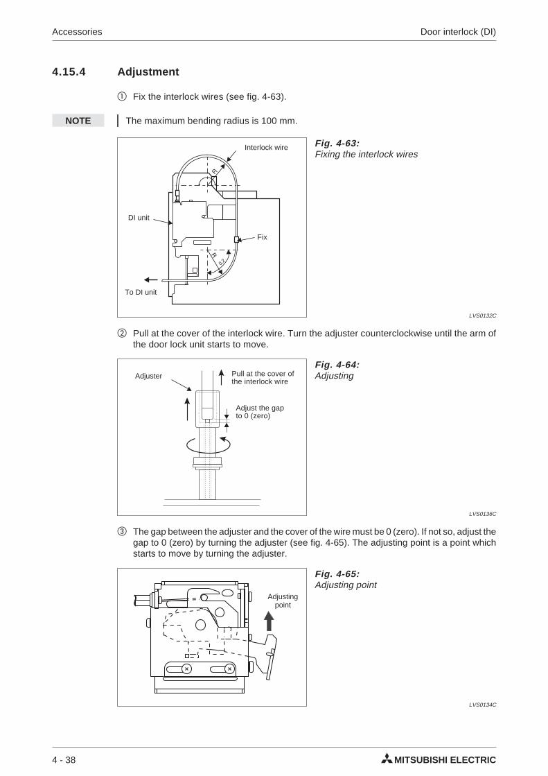
4.15.4 Adjustment
Fix the interlock wires (see fig. 4-63).
NOTE The maximum bending radius is 100 mm.
Pull at the cover of the interlock wire. Turn the adjuster counterclockwise until the arm ofthe door lock unit starts to move.
The gap between the adjuster and the cover of the wire must be 0 (zero). If not so, adjust thegap to 0 (zero) by turning the adjuster (see fig. 4-65). The adjusting point is a point whichstarts to move by turning the adjuster.
4 - 38 MITSUBISHI ELECTRIC
Accessories Door interlock (DI)
R
R
0,2
Fig. 4-63:Fixing the interlock wires
LVS0132C
Interlock wire
DI unit
Fix
To DI unit
Fig. 4-64:Adjusting
LVS0136C
Pull at the cover ofthe interlock wire
Adjuster
Adjust the gapto 0 (zero)
~
Fig. 4-65:Adjusting point
LVS0134C
Adjustingpoint
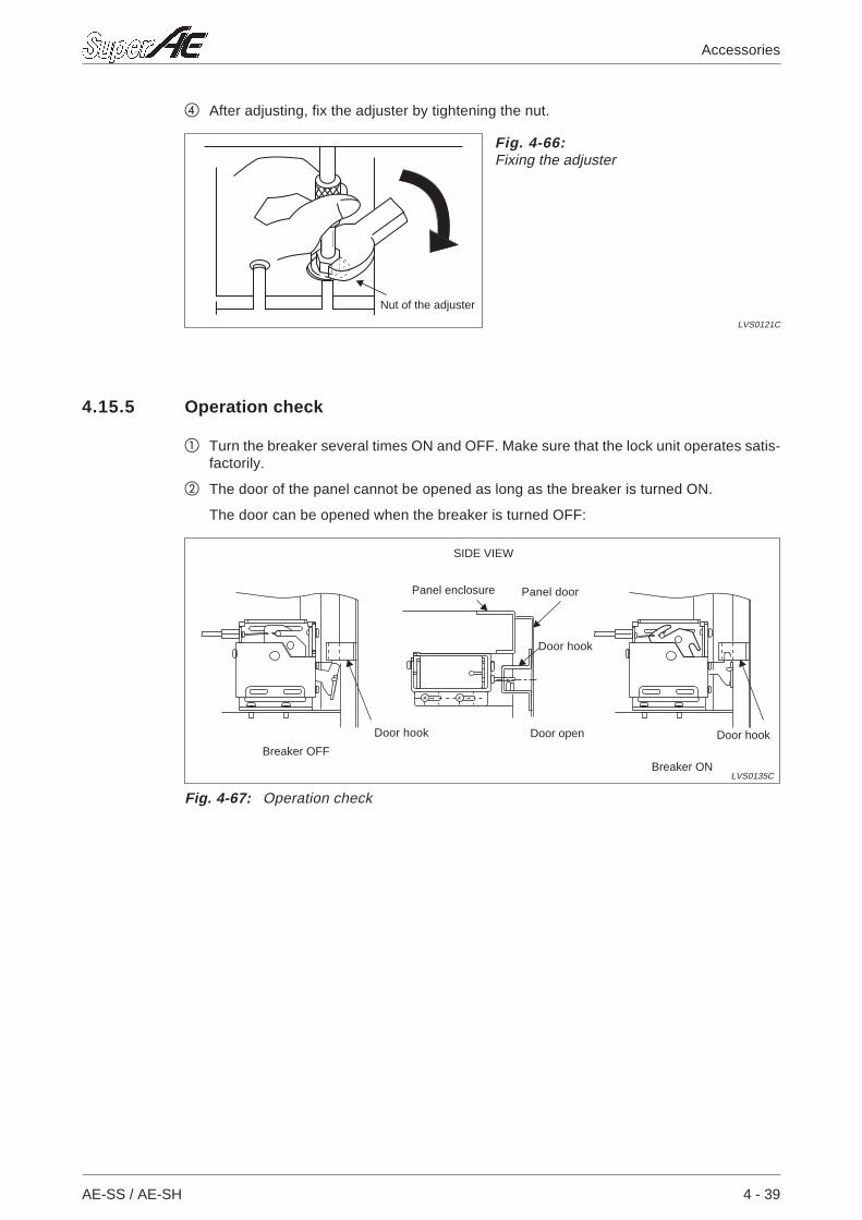
After adjusting, fix the adjuster by tightening the nut.
4.15.5 Operation check
Turn the breaker several times ON and OFF. Make sure that the lock unit operates satis-factorily.
The door of the panel cannot be opened as long as the breaker is turned ON.
The door can be opened when the breaker is turned OFF:
AE-SS / AE-SH 4 - 39
Accessories
Fig. 4-66:Fixing the adjuster
LVS0121C
Nut of the adjuster
~ ~
Fig. 4-67: Operation check
LVS0135C
SIDE VIEW
Breaker OFF
Door hook
Panel doorPanel enclosure
Door openDoor hook
Breaker ON
Door hook
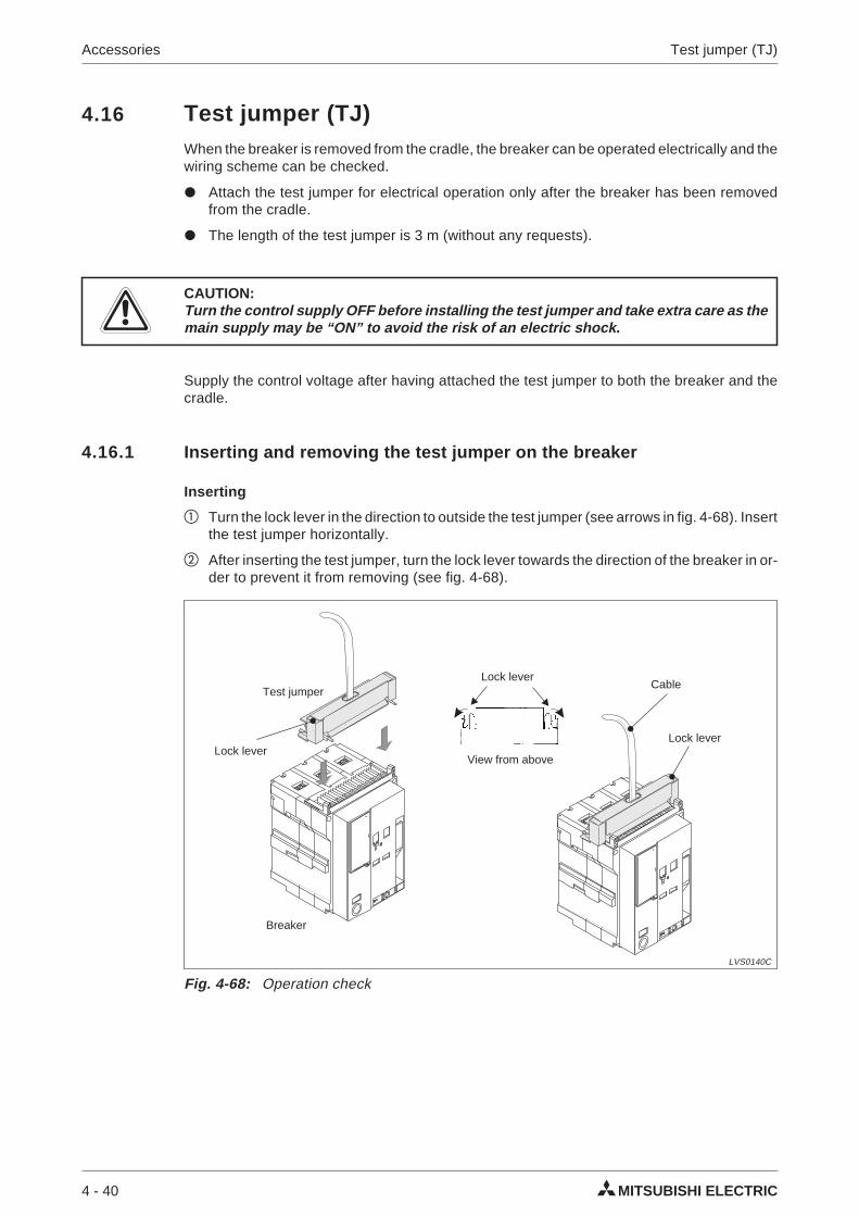
4.16 Test jumper (TJ)When the breaker is removed from the cradle, the breaker can be operated electrically and thewiring scheme can be checked.
Attach the test jumper for electrical operation only after the breaker has been removedfrom the cradle.
The length of the test jumper is 3 m (without any requests).
ECAUTION:Turn the control supply OFF before installing the test jumper and take extra care as themain supply may be “ON” to avoid the risk of an electric shock.
Supply the control voltage after having attached the test jumper to both the breaker and thecradle.
4.16.1 Inserting and removing the test jumper on the breaker
Inserting
Turn the lock lever in the direction to outside the test jumper (see arrows in fig. 4-68). Insertthe test jumper horizontally.
After inserting the test jumper, turn the lock lever towards the direction of the breaker in or-der to prevent it from removing (see fig. 4-68).
4 - 40 MITSUBISHI ELECTRIC
Accessories Test jumper (TJ)
Fig. 4-68: Operation check
LVS0140C
Lock lever
Cable
Lock lever
Breaker
Test jumper
View from above
Lock lever
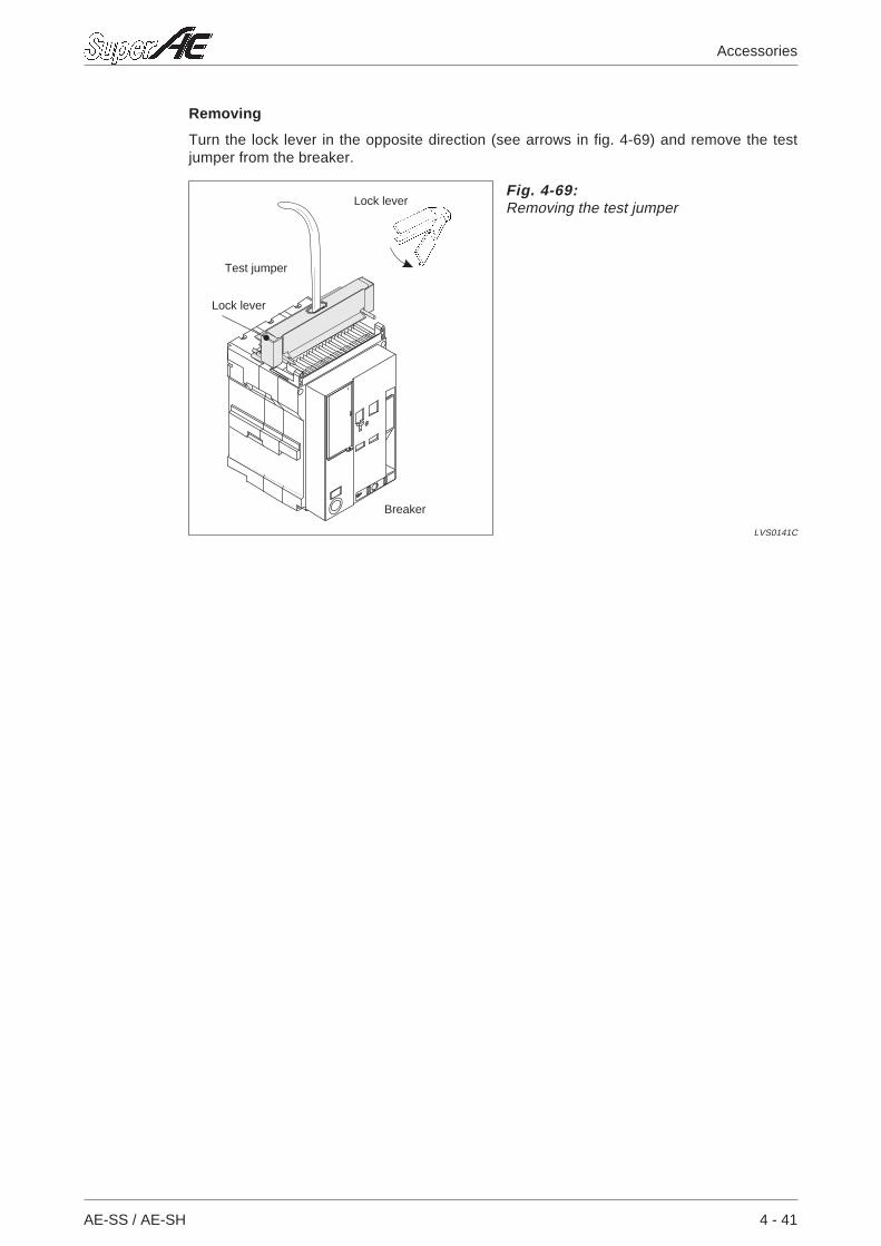
Removing
Turn the lock lever in the opposite direction (see arrows in fig. 4-69) and remove the testjumper from the breaker.
AE-SS / AE-SH 4 - 41
Accessories
Fig. 4-69:Removing the test jumper
LVS0141C
Lock lever
Lock lever
Breaker
Test jumper
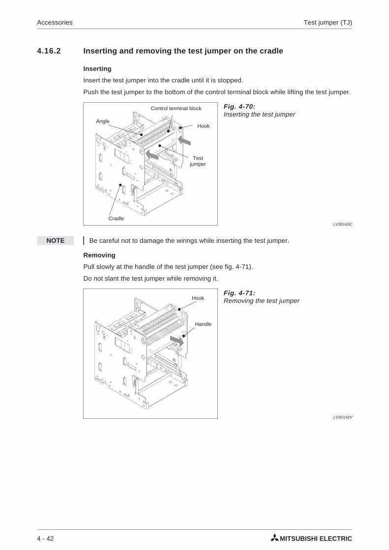
4.16.2 Inserting and removing the test jumper on the cradle
Inserting
Insert the test jumper into the cradle until it is stopped.
Push the test jumper to the bottom of the control terminal block while lifting the test jumper.
NOTE Be careful not to damage the wirings while inserting the test jumper.
Removing
Pull slowly at the handle of the test jumper (see fig. 4-71).
Do not slant the test jumper while removing it.
4 - 42 MITSUBISHI ELECTRIC
Accessories Test jumper (TJ)
Fig. 4-70:Inserting the test jumper
LVS0143CCradle
Hook
Testjumper
Angle
Control terminal block
Fig. 4-71:Removing the test jumper
LVS0142V
Handle
Hook
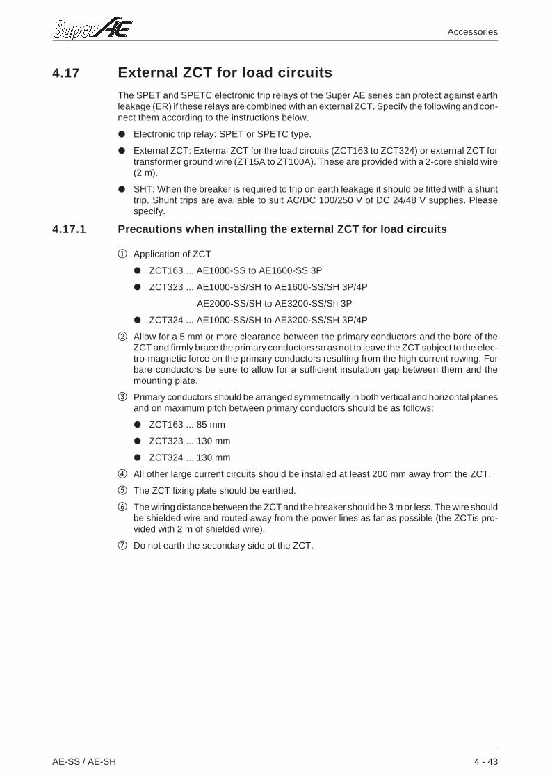
4.17 External ZCT for load circuitsThe SPET and SPETC electronic trip relays of the Super AE series can protect against earthleakage (ER) if these relays are combined with an external ZCT. Specify the following and con-nect them according to the instructions below.
Electronic trip relay: SPET or SPETC type.
External ZCT: External ZCT for the load circuits (ZCT163 to ZCT324) or external ZCT fortransformer ground wire (ZT15A to ZT100A). These are provided with a 2-core shield wire(2 m).
SHT: When the breaker is required to trip on earth leakage it should be fitted with a shunttrip. Shunt trips are available to suit AC/DC 100/250 V of DC 24/48 V supplies. Pleasespecify.
4.17.1 Precautions when installing the external ZCT for load circuits
Application of ZCT
ZCT163 ... AE1000-SS to AE1600-SS 3P
ZCT323 ... AE1000-SS/SH to AE1600-SS/SH 3P/4P
AE2000-SS/SH to AE3200-SS/Sh 3P
ZCT324 ... AE1000-SS/SH to AE3200-SS/SH 3P/4P
Allow for a 5 mm or more clearance between the primary conductors and the bore of theZCT and firmly brace the primary conductors so as not to leave the ZCT subject to the elec-tro-magnetic force on the primary conductors resulting from the high current rowing. Forbare conductors be sure to allow for a sufficient insulation gap between them and themounting plate.
Primary conductors should be arranged symmetrically in both vertical and horizontal planesand on maximum pitch between primary conductors should be as follows:
ZCT163 ... 85 mm
ZCT323 ... 130 mm
ZCT324 ... 130 mm
All other large current circuits should be installed at least 200 mm away from the ZCT.
The ZCT fixing plate should be earthed.
The wiring distance between the ZCT and the breaker should be 3 m or less. The wire shouldbe shielded wire and routed away from the power lines as far as possible (the ZCTis pro-vided with 2 m of shielded wire).
Do not earth the secondary side ot the ZCT.
AE-SS / AE-SH 4 - 43
Accessories
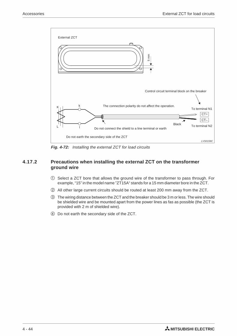
4.17.2 Precautions when installing the external ZCT on the transformerground wire
Select a ZCT bore that allows the ground wire of the transformer to pass through. Forexample, “15” in the model name ”ZT15A“ stands for a 15 mm diameter bore in the ZCT.
All other large current circuits should be routed at least 200 mm away from the ZCT.
The wiring distance between the ZCT and the breaker should be 3 m or less. The wire shouldbe shielded wire and be mounted apart from the power lines as fas as possible (the ZCT isprovided with 2 m of shielded wire).
Do not earth the secondary side of the ZCT.
4 - 44 MITSUBISHI ELECTRIC
Accessories External ZCT for load circuits
CT–
CT+
k
l
K
L
Fig. 4-72: Installing the external ZCT for load circuits
LVS0159C
Do not connect the shield to a line terminal or earth
Control circuit terminal block on the breaker
To terminal N1The connection polarity do not affect the operation.
Do not earth the secondary side of the ZCT
Black To terminal N2
5m
m
External ZCT
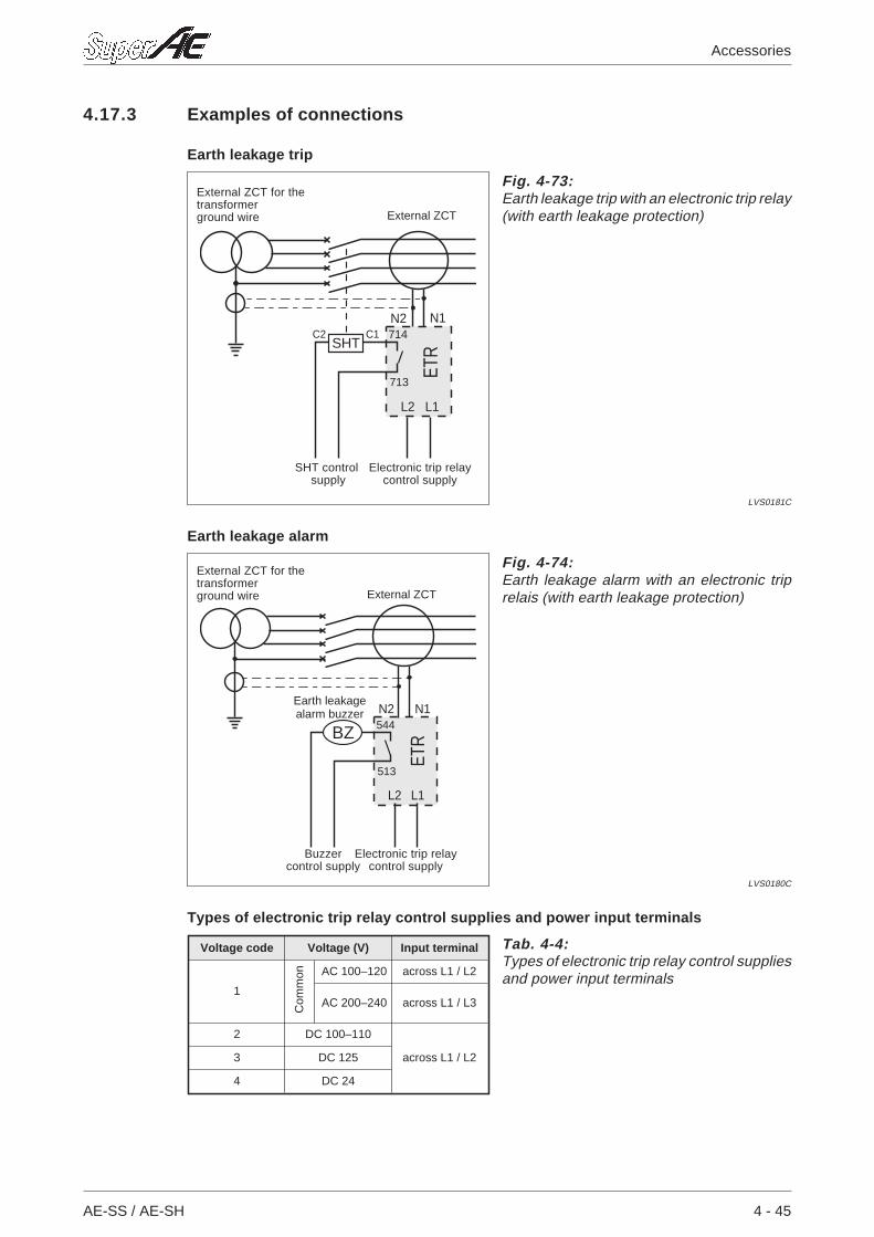
4.17.3 Examples of connections
Earth leakage trip
Earth leakage alarm
Types of electronic trip relay control supplies and power input terminals
AE-SS / AE-SH 4 - 45
Accessories
ETR
N2
L2
C2 C1N1
L1
SHT
713
714
Fig. 4-73:Earth leakage trip with an electronic trip relay(with earth leakage protection)
LVS0181C
Electronic trip relaycontrol supply
External ZCT
External ZCT for thetransformerground wire
SHT controlsupply
ETRBZ
N2 N1
L1
513
544
L2
Fig. 4-74:Earth leakage alarm with an electronic triprelais (with earth leakage protection)
LVS0180C
Electronic trip relaycontrol supply
External ZCT
External ZCT for thetransformerground wire
Buzzercontrol supply
Earth leakagealarm buzzer
Voltage code Voltage (V) Input terminal
1
AC 100–120 across L1 / L2
AC 200–240 across L1 / L3
2 DC 100–110
across L1 / L23 DC 125
4 DC 24
Tab. 4-4:Types of electronic trip relay control suppliesand power input terminals
Com
mon
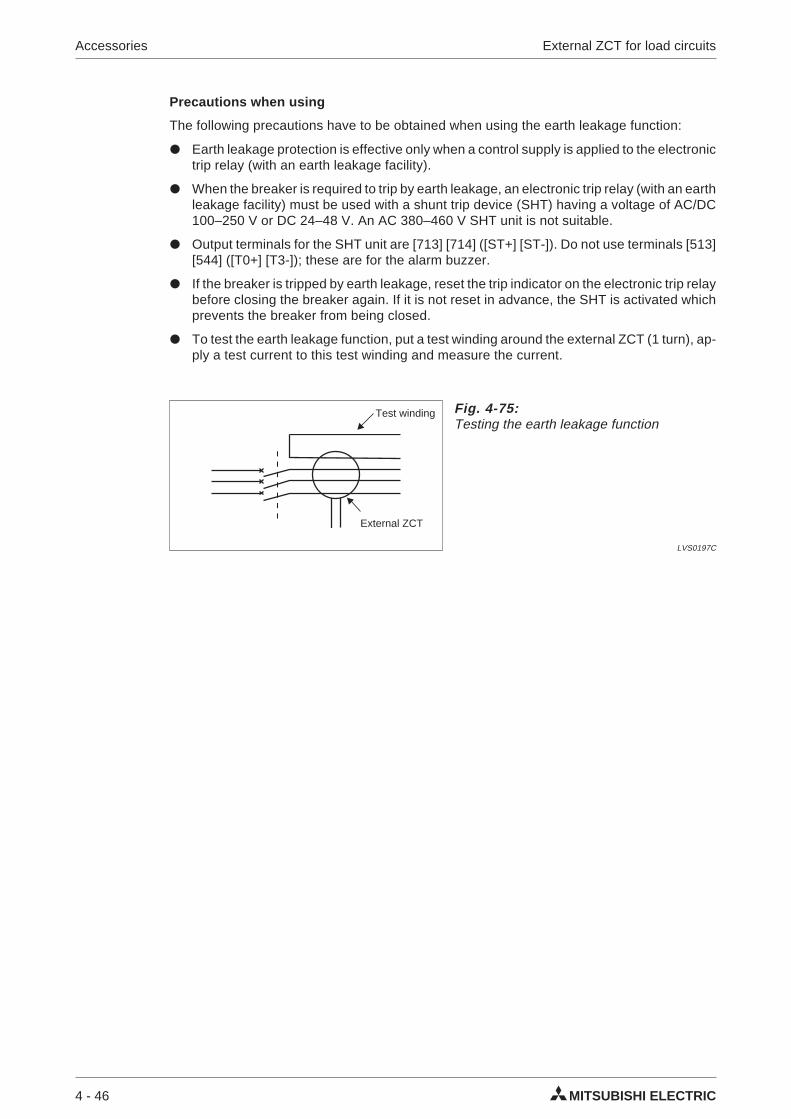
Precautions when using
The following precautions have to be obtained when using the earth leakage function:
Earth leakage protection is effective only when a control supply is applied to the electronictrip relay (with an earth leakage facility).
When the breaker is required to trip by earth leakage, an electronic trip relay (with an earthleakage facility) must be used with a shunt trip device (SHT) having a voltage of AC/DC100–250 V or DC 24–48 V. An AC 380–460 V SHT unit is not suitable.
Output terminals for the SHT unit are [713] [714] ([ST+] [ST-]). Do not use terminals [513][544] ([T0+] [T3-]); these are for the alarm buzzer.
If the breaker is tripped by earth leakage, reset the trip indicator on the electronic trip relaybefore closing the breaker again. If it is not reset in advance, the SHT is activated whichprevents the breaker from being closed.
To test the earth leakage function, put a test winding around the external ZCT (1 turn), ap-ply a test current to this test winding and measure the current.
4 - 46 MITSUBISHI ELECTRIC
Accessories External ZCT for load circuits
Fig. 4-75:Testing the earth leakage function
LVS0197C
Test winding
External ZCT
4.18 Push-button coverThis provides protection to the ON and OFF push-buttons against inadvertent operation. Toopen or close the breaker, push up the cover for the push-button required and press thispush-button. A padlock facility is available (the padlock has to be provided by the customer)which prevents manual operation from the front side of the breaker.
4.18.1 Installation
Place the button covers and the button cover frame over the push-buttons as shown in thefollowing fig. 4-76.
Mount the button cover on the AE-SS cover by tighteing the tapping screw (tighteningtorque: 1.2–1.5 Nm).
NOTE Apply bonding agent to the top of the screw, if a locking of the screw is required.
For securing the button cover a standard padlock can be used.
AE-SS / AE-SH 4 - 47
Accessories
DISCHARGED
OFF
Fig. 4-76:Installation of the push-button covers
LVS0150C
Tappingscrew
1.2–1.5 Nm
Fig. 4-77:Applying the padlock
LVS0151C
Padlock
Push downthe cover.
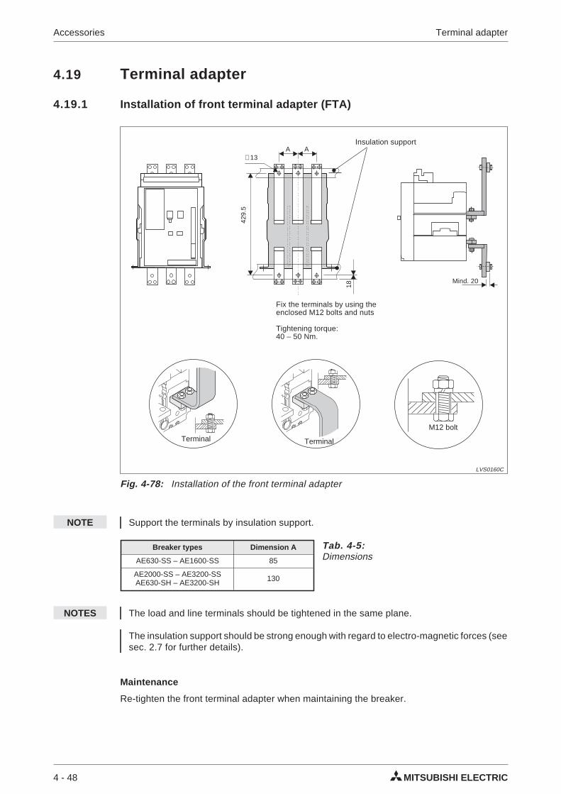
4.19 Terminal adapter
4.19.1 Installation of front terminal adapter (FTA)
NOTE Support the terminals by insulation support.
NOTES The load and line terminals should be tightened in the same plane.
The insulation support should be strong enough with regard to electro-magnetic forces (seesec. 2.7 for further details).
Maintenance
Re-tighten the front terminal adapter when maintaining the breaker.
4 - 48 MITSUBISHI ELECTRIC
Accessories Terminal adapter
∅ 13
Fig. 4-78: Installation of the front terminal adapter
LVS0160C
Insulation support
Fix the terminals by using theenclosed M12 bolts and nuts
Tightening torque:40 – 50 Nm.
429.
5
18
Mind. 20
A A
M12 bolt
Terminal Terminal
Breaker types Dimension A
AE630-SS – AE1600-SS 85
AE2000-SS – AE3200-SSAE630-SH – AE3200-SH 130
Tab. 4-5:Dimensions
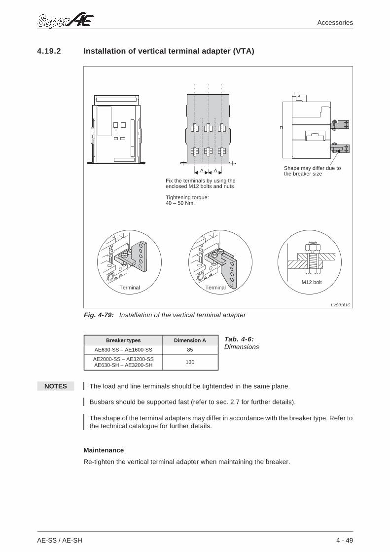
4.19.2 Installation of vertical terminal adapter (VTA)
NOTES The load and line terminals should be tightended in the same plane.
Busbars should be supported fast (refer to sec. 2.7 for further details).
The shape of the terminal adapters may differ in accordance with the breaker type. Refer tothe technical catalogue for further details.
Maintenance
Re-tighten the vertical terminal adapter when maintaining the breaker.
AE-SS / AE-SH 4 - 49
Accessories
Fix the terminals by using theenclosed M12 bolts and nuts
Tightening torque:40 – 50 Nm.
Fig. 4-79: Installation of the vertical terminal adapter
LVS0161C
TerminalM12 bolt
AA Shape may differ due tothe breaker size
Terminal
Breaker types Dimension A
AE630-SS – AE1600-SS 85
AE2000-SS – AE3200-SSAE630-SH – AE3200-SH 130
Tab. 4-6:Dimensions
4 - 50 MITSUBISHI ELECTRIC
Accessories Terminal adapter
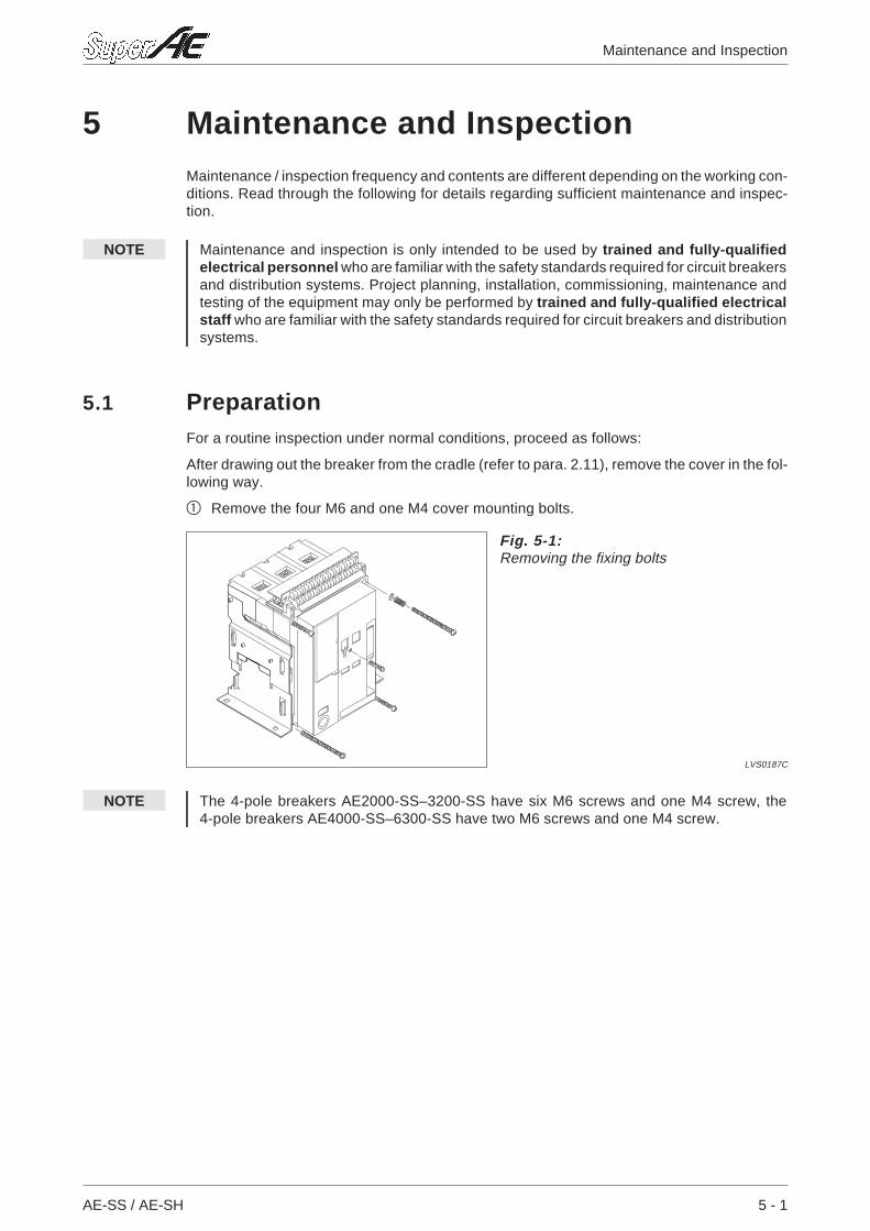
5 Maintenance and InspectionMaintenance / inspection frequency and contents are different depending on the working con-ditions. Read through the following for details regarding sufficient maintenance and inspec-tion.
NOTE Maintenance and inspection is only intended to be used by trained and fully-qualifiedelectrical personnel who are familiar with the safety standards required for circuit breakersand distribution systems. Project planning, installation, commissioning, maintenance andtesting of the equipment may only be performed by trained and fully-qualified electricalstaff who are familiar with the safety standards required for circuit breakers and distributionsystems.
5.1 PreparationFor a routine inspection under normal conditions, proceed as follows:
After drawing out the breaker from the cradle (refer to para. 2.11), remove the cover in the fol-lowing way.
Remove the four M6 and one M4 cover mounting bolts.
NOTE The 4-pole breakers AE2000-SS–3200-SS have six M6 screws and one M4 screw, the4-pole breakers AE4000-SS–6300-SS have two M6 screws and one M4 screw.
AE-SS / AE-SH 5 - 1
Maintenance and Inspection
Fig. 5-1:Removing the fixing bolts
LVS0187C
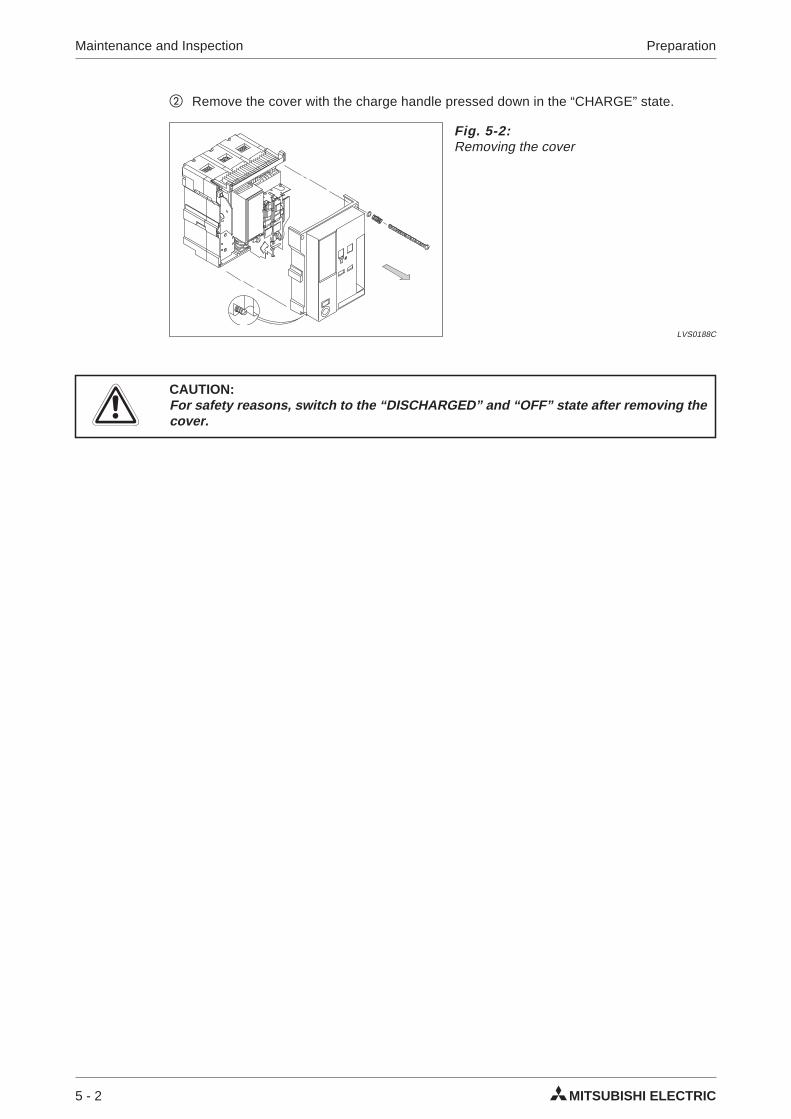
Remove the cover with the charge handle pressed down in the “CHARGE” state.
ECAUTION:For safety reasons, switch to the “DISCHARGED” and “OFF” state after removing thecover.
5 - 2 MITSUBISHI ELECTRIC
Maintenance and Inspection Preparation
Fig. 5-2:Removing the cover
LVS0188C
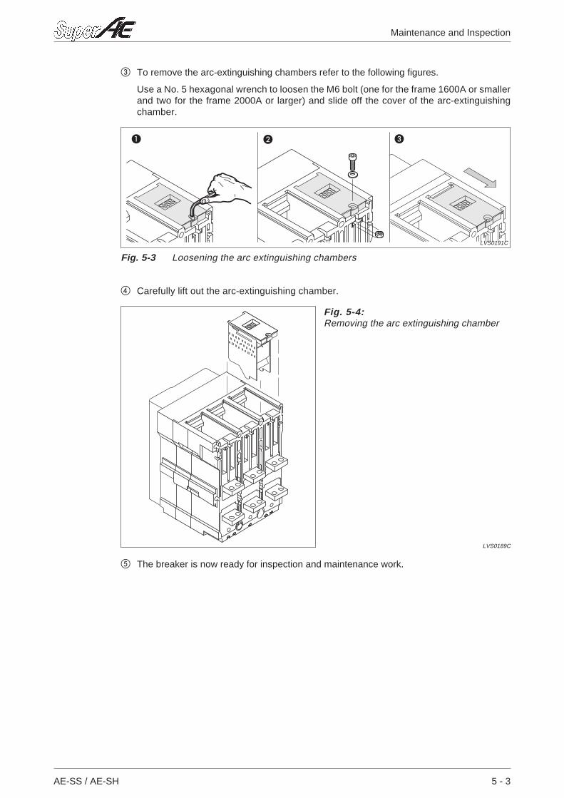
To remove the arc-extinguishing chambers refer to the following figures.
Use a No. 5 hexagonal wrench to loosen the M6 bolt (one for the frame 1600A or smallerand two for the frame 2000A or larger) and slide off the cover of the arc-extinguishingchamber.
Carefully lift out the arc-extinguishing chamber.
The breaker is now ready for inspection and maintenance work.
AE-SS / AE-SH 5 - 3
Maintenance and Inspection
Fig. 5-4:Removing the arc extinguishing chamber
LVS0189C
Fig. 5-3 Loosening the arc extinguishing chambers
LVS0191C
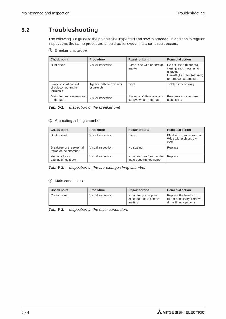
5.2 TroubleshootingThe following is a guide to the points to be inspected and how to proceed. In addition to regularinspections the same procedure should be followed, if a short circuit occurs.
Breaker unit proper
Arc-extinguishing chamber
Main conductors
5 - 4 MITSUBISHI ELECTRIC
Maintenance and Inspection Troubleshooting
Check point Procedure Repair criteria Remedial action
Dust or dirt Visual inspection Clean, and with no foreignmatter
Do not use a thinner toclean plastic material asa cover.Use ethyl alcohol (ethanol)to remove extreme dirt
Looseness of controlcircuit contact mainterminals
Tighten with screwdriveror wrench
Tight Tighten if necessary
Distortion, excessive wearor damage Visual inspection Absence of distortion, ex-
cessive wear or damageRemove cause and re-place parts
Tab. 5-1: Inspection of the breaker unit
Check point Procedure Repair criteria Remedial action
Soot or dust Visual inspection Clean Blast with compressed air.Wipe with a clean, drycloth
Breakage of the externalframe of the chamber
Visual inspection No scaling Replace
Melting of arc-extinguishing plate
Visual inspection No more than 5 mm of theplate edge melted away
Replace
Tab. 5-2: Inspection of the arc-extinguishing chamber
Check point Procedure Repair criteria Remedial action
Contact wear Visual inspection No underlying copperexposed due to contactmelting
Replace the breaker.(If not necessary, removedirt with sandpaper.)
Tab. 5-3: Inspection of the main conductors
5.3 Guidelines for inspections and replacement
5.3.1 Introduction
ACB’s should be periodically inspected
to detect anomalous parts at an early stage
to maintain the performance of the ACB through timely renewal of consumable and de-grading parts
to prevent accidents that may arise from the end of the lifetime of the equipment.
MITSUBISHI ELECTRIC suggests the following guidelines for inspection and renewals, fre-quency of inspections and inspection details. Please read these upon of the equipment.
NOTE Maintenance and inspection is only intended to be used by trained and fully-qualifiedelectrical personnel who are familiar with the safety standards required for circuit breakersand distribution systems. Project planning, installation, commissioning, maintenance andtesting of the equipment may only be performed by trained and fully-qualified electricalstaff who are familiar with the safety standards required for circuit breakers and distributionsystems.
5.3.2 Inspections and renewals according to period and environment of usage
AE-SS / AE-SH 5 - 5
Maintenance and Inspection
Degree of usage Environment Specific examples Guidlinesfor inspection
Guidelinesfor renewal
Generalusageenvironments
1 Location where the air isalways clean and dry
Dustproof andairconditioned electricrooms, etc.
Once every2~3 years
Within approx.15 years
2 Indoor locations with littledust, etc.Locations withoutcorrosiove gases
Distribution panels inboxes and distributionpanels in individual electricrooms that are notdustproof andair-conditioned
Poorenvironments
1 Locations with salinity,high temperature andgases such as sulphurdioxide and hydrogensulphide
Geothermal power plants,waste water, treatmentplants, iron mills, paperfactories, pulp factories,etc.
Once a year Within approx.7 years
2 Locations with especiallysevere corrosive gas anddust conditions and wherehumans cannot stay for along period of time
Chemical factories,quarries, mining areas,etc.
Once everyhalf a year
Within approx.5 years
Tab.5-4: Inspections and renewals according to period and environment of usage
5.3.3 Inspections and replacement according to number of operation cycles
5 - 6 MITSUBISHI ELECTRIC
Maintenance and Inspection Guidelines for inspections and replacement
Breaker
Guidelines forinspection Limit of number of operation cycles with rated current
Operation cycles Operation cycles
with ratedcurrent
withoutload per hour with rated
currentwithout
load totalwith 6x
rated cur-rent
AE1000 -SSevery 500
every 200020
5000
10000 10000 12
AE1250-SS
AE1600-SS
every 300AE2000-SS1500
AE2500-SS
AE3200-SS every 100 10 1000
AE4000-SSA 3P every 100 every 1000 20
500
5000 5000 6
AE4000-SSA 4P every 50 every 400
10
4000 4000
3
AE4000-SSC
every 50
every 1000 5000 5000
AE4000-SS
every 400 2000 2000AE5000-SS
AE6300-SS
AE1000-SHevery 500
every 200020
5000
10000 10000 12
AE1250-SH
AE1600-SH
every 300
2000
AE2000-SH1500
AE2500-SH
AE3200-SH every 100 10 1000
Tab. 5-5: Inspections and renewals according to number of operation cycles
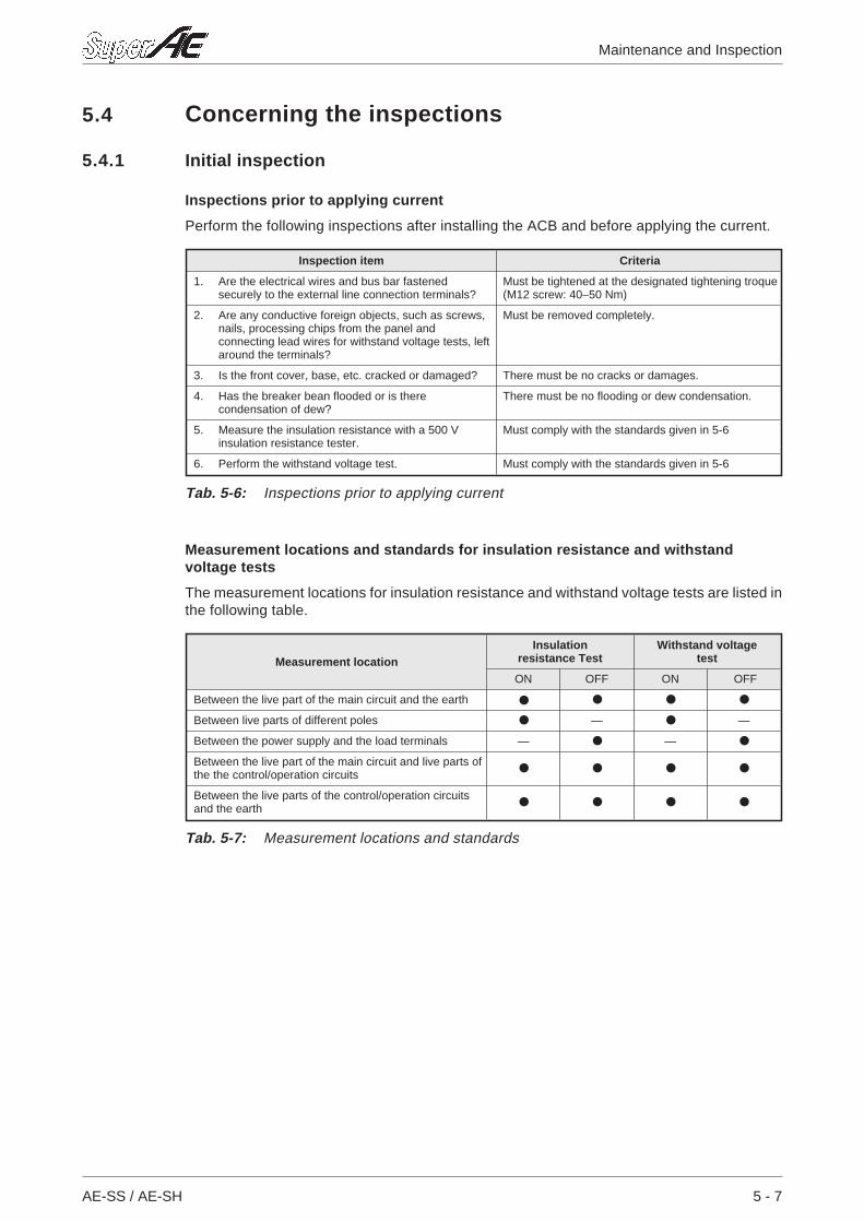
5.4 Concerning the inspections
5.4.1 Initial inspection
Inspections prior to applying current
Perform the following inspections after installing the ACB and before applying the current.
Measurement locations and standards for insulation resistance and withstandvoltage tests
The measurement locations for insulation resistance and withstand voltage tests are listed inthe following table.
AE-SS / AE-SH 5 - 7
Maintenance and Inspection
Inspection item Criteria
1. Are the electrical wires and bus bar fastenedsecurely to the external line connection terminals?
Must be tightened at the designated tightening troque(M12 screw: 40–50 Nm)
2. Are any conductive foreign objects, such as screws,nails, processing chips from the panel andconnecting lead wires for withstand voltage tests, leftaround the terminals?
Must be removed completely.
3. Is the front cover, base, etc. cracked or damaged? There must be no cracks or damages.
4. Has the breaker bean flooded or is therecondensation of dew?
There must be no flooding or dew condensation.
5. Measure the insulation resistance with a 500 Vinsulation resistance tester.
Must comply with the standards given in 5-6
6. Perform the withstand voltage test. Must comply with the standards given in 5-6
Tab. 5-6: Inspections prior to applying current
Measurement locationInsulation
resistance TestWithstand voltage
test
ON OFF ON OFF
Between the live part of the main circuit and the earth
Between live parts of different poles — —
Between the power supply and the load terminals — —
Between the live part of the main circuit and live parts ofthe the control/operation circuits
Between the live parts of the control/operation circuitsand the earth
Tab. 5-7: Measurement locations and standards

Standards for insulation resistance and withstand voltage tests
Insulation ResistanceTest: Must be no less than 5MΩ(must be no less than 100 MΩ for the ACB alone).
Withstand Voltage Test: Between the live part of the main circuit and the earth:3500 V
Between live parts of different poles:3500 V
Between the power supply and the load terminals:3500 V
Between the live part of the main circuit and thelive parts of the control/operation ciruits:3500 V
Between the live parts of the control/operation circuitsand the earth:2000 V (is not, according to the indication on the nameplate)
ECAUTION:In the case of dielectric check of panel board, remove the control source wires of UVTcontroller, otherwise UVT controller may be broken.
5 - 8 MITSUBISHI ELECTRIC
Maintenance and Inspection Concerning the inspections
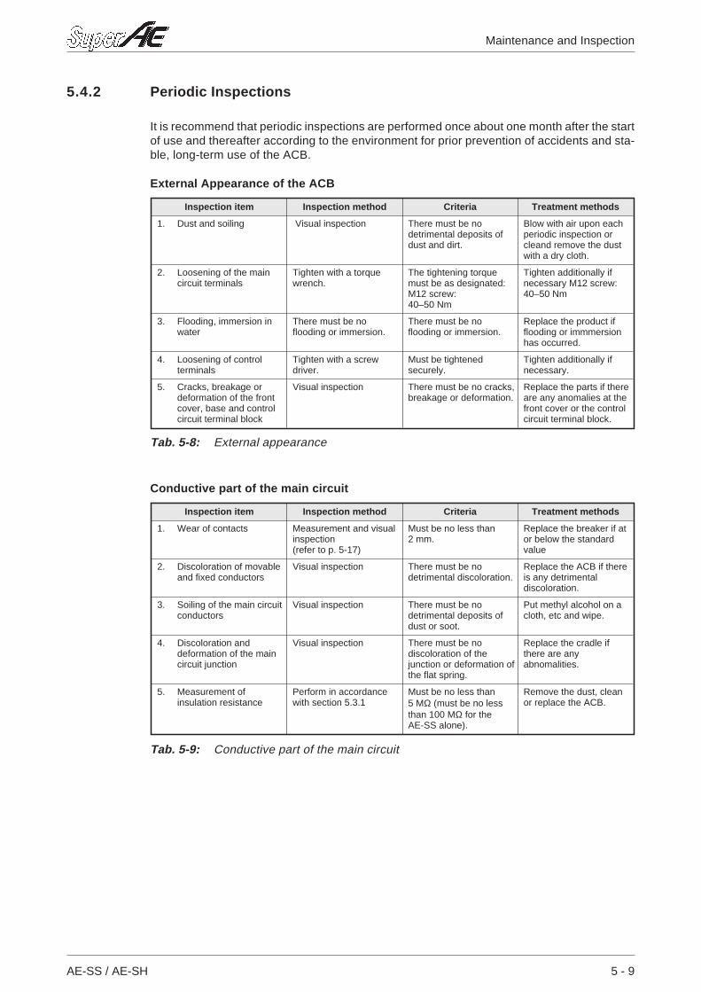
5.4.2 Periodic Inspections
It is recommend that periodic inspections are performed once about one month after the startof use and thereafter according to the environment for prior prevention of accidents and sta-ble, long-term use of the ACB.
External Appearance of the ACB
Conductive part of the main circuit
AE-SS / AE-SH 5 - 9
Maintenance and Inspection
Inspection item Inspection method Criteria Treatment methods
1. Dust and soiling Visual inspection There must be nodetrimental deposits ofdust and dirt.
Blow with air upon eachperiodic inspection orcleand remove the dustwith a dry cloth.
2. Loosening of the maincircuit terminals
Tighten with a torquewrench.
The tightening torquemust be as designated:M12 screw:40–50 Nm
Tighten additionally ifnecessary M12 screw:40–50 Nm
3. Flooding, immersion inwater
There must be noflooding or immersion.
There must be noflooding or immersion.
Replace the product ifflooding or immmersionhas occurred.
4. Loosening of controlterminals
Tighten with a screwdriver.
Must be tightenedsecurely.
Tighten additionally ifnecessary.
5. Cracks, breakage ordeformation of the frontcover, base and controlcircuit terminal block
Visual inspection There must be no cracks,breakage or deformation.
Replace the parts if thereare any anomalies at thefront cover or the controlcircuit terminal block.
Tab. 5-8: External appearance
Inspection item Inspection method Criteria Treatment methods
1. Wear of contacts Measurement and visualinspection(refer to p. 5-17)
Must be no less than2 mm.
Replace the breaker if ator below the standardvalue
2. Discoloration of movableand fixed conductors
Visual inspection There must be nodetrimental discoloration.
Replace the ACB if thereis any detrimentaldiscoloration.
3. Soiling of the main circuitconductors
Visual inspection There must be nodetrimental deposits ofdust or soot.
Put methyl alcohol on acloth, etc and wipe.
4. Discoloration anddeformation of the maincircuit junction
Visual inspection There must be nodiscoloration of thejunction or deformation ofthe flat spring.
Replace the cradle ifthere are anyabnomalities.
5. Measurement ofinsulation resistance
Perform in accordancewith section 5.3.1
Must be no less than5 MΩ (must be no lessthan 100 MΩ for theAE-SS alone).
Remove the dust, cleanor replace the ACB.
Tab. 5-9: Conductive part of the main circuit
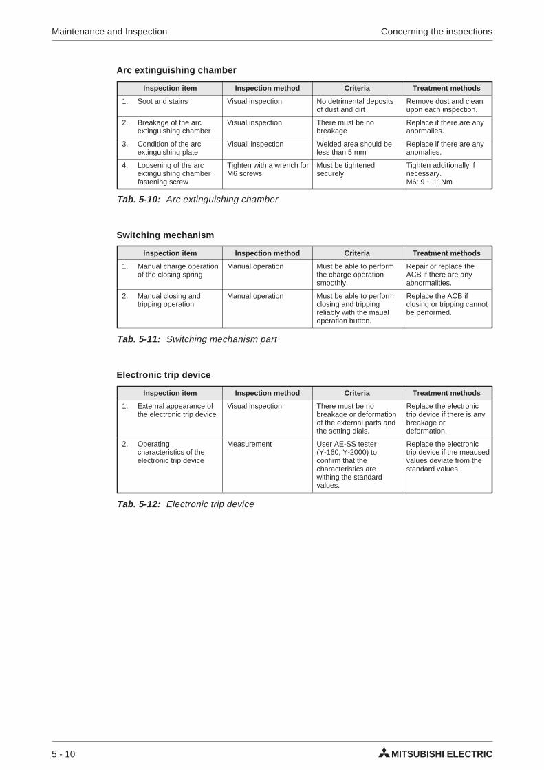
Arc extinguishing chamber
Switching mechanism
Electronic trip device
5 - 10 MITSUBISHI ELECTRIC
Maintenance and Inspection Concerning the inspections
Inspection item Inspection method Criteria Treatment methods
1. Soot and stains Visual inspection No detrimental depositsof dust and dirt
Remove dust and cleanupon each inspection.
2. Breakage of the arcextinguishing chamber
Visual inspection There must be nobreakage
Replace if there are anyanormalies.
3. Condition of the arcextinguishing plate
Visuall inspection Welded area should beless than 5 mm
Replace if there are anyanomalies.
4. Loosening of the arcextinguishing chamberfastening screw
Tighten with a wrench forM6 screws.
Must be tightenedsecurely.
Tighten additionally ifnecessary.M6: 9 ~ 11Nm
Tab. 5-10: Arc extinguishing chamber
Inspection item Inspection method Criteria Treatment methods
1. Manual charge operationof the closing spring
Manual operation Must be able to performthe charge operationsmoothly.
Repair or replace theACB if there are anyabnormalities.
2. Manual closing andtripping operation
Manual operation Must be able to performclosing and trippingreliably with the maualoperation button.
Replace the ACB ifclosing or tripping cannotbe performed.
Tab. 5-11: Switching mechanism part
Inspection item Inspection method Criteria Treatment methods
1. External appearance ofthe electronic trip device
Visual inspection There must be nobreakage or deformationof the external parts andthe setting dials.
Replace the electronictrip device if there is anybreakage ordeformation.
2. Operatingcharacteristics of theelectronic trip device
Measurement User AE-SS tester(Y-160, Y-2000) toconfirm that thecharacteristics arewithing the standardvalues.
Replace the electronictrip device if the meausedvalues deviate from thestandard values.
Tab. 5-12: Electronic trip device
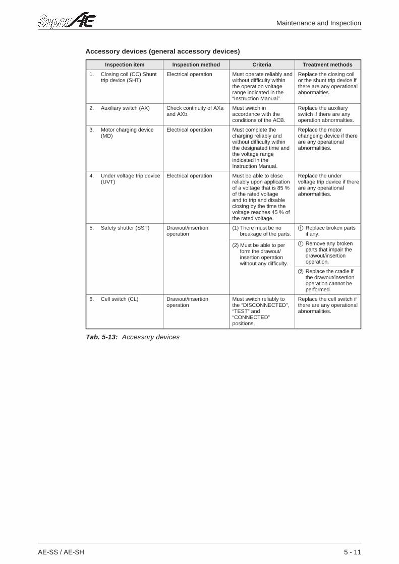
Accessory devices (general accessory devices)
AE-SS / AE-SH 5 - 11
Maintenance and Inspection
Inspection item Inspection method Criteria Treatment methods
1. Closing coil (CC) Shunttrip device (SHT)
Electrical operation Must operate reliably andwithout difficulty withinthe operation voltagerange indicated in the“Instruction Manual”.
Replace the closing coilor the shunt trip device ifthere are any operationalabnormalties.
2. Auxiliary switch (AX) Check continuity of AXaand AXb.
Must switch inaccordance with theconditions of the ACB.
Replace the auxiliaryswitch if there are anyoperation abnormalties.
3. Motor charging device(MD)
Electrical operation Must complete thecharging reliably andwithout difficulty withinthe designated time andthe voltage rangeindicated in theInstruction Manual.
Replace the motorchangeing device if thereare any operationalabnormalities.
4. Under voltage trip device(UVT)
Electrical operation Must be able to closereliably upon applicationof a voltage that is 85 %of the rated voltageand to trip and disableclosing by the time thevoltage reaches 45 % ofthe rated voltage.
Replace the undervoltage trip device if thereare any operationalabnormalities.
5. Safety shutter (SST) Drawout/insertionoperation
(1) There must be nobreakage of the parts.
Replace broken partsif any.
(2) Must be able to perform the drawout/insertion operationwithout any difficulty.
Remove any brokenparts that impair thedrawout/insertionoperation.
Replace the cradle ifthe drawout/insertionoperation cannot beperformed.
6. Cell switch (CL) Drawout/insertionoperation
Must switch reliably tothe “DISCONNECTED”,“TEST” and“CONNECTED”positions.
Replace the cell switch ifthere are any operationalabnormalities.
Tab. 5-13: Accessory devices
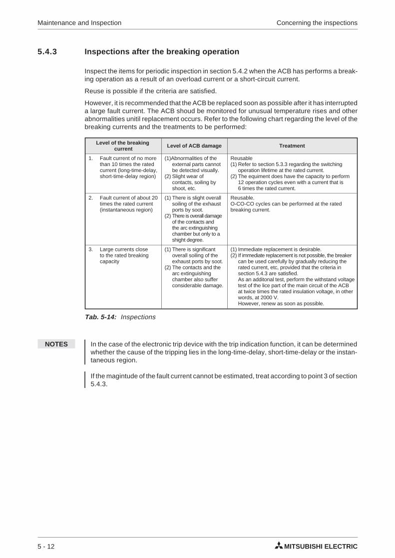
5.4.3 Inspections after the breaking operation
Inspect the items for periodic inspection in section 5.4.2 when the ACB has performs a break-ing operation as a result of an overload current or a short-circuit current.
Reuse is possible if the criteria are satisfied.
However, it is recommended that the ACB be replaced soon as possible after it has interrupteda large fault current. The ACB shoud be monitored for unusual temperature rises and otherabnormalities unitil replacement occurs. Refer to the following chart regarding the level of thebreaking currents and the treatments to be performed:
NOTES In the case of the electronic trip device with the trip indication function, it can be determinedwhether the cause of the tripping lies in the long-time-delay, short-time-delay or the instan-taneous region.
If the magintude of the fault current cannot be estimated, treat according to point 3 of section5.4.3.
5 - 12 MITSUBISHI ELECTRIC
Maintenance and Inspection Concerning the inspections
Level of the breakingcurrent Level of ACB damage Treatment
1. Fault current of no morethan 10 times the ratedcurrent (long-time-delay,short-time-delay region)
(1)Abnormalities of theexternal parts cannotbe detected visually.
(2) Slight wear ofcontacts, soiling byshoot, etc.
Reusable(1) Refer to section 5.3.3 regarding the switching
operation lifetime at the rated current.(2) The equiment does have the capacity to perform
12 operation cycles even with a current that is6 times the rated current.
2. Fault current of about 20times the rated current(instantaneous region)
(1) There is slight overallsoiling of the exhaustports by soot.
(2) There is overall damageof the contacts andthe arc extinguishingchamber but only to ashight degree.
Reusable.O-CO-CO cycles can be performed at the ratedbreaking current.
3. Large currents closeto the rated breakingcapacity
(1) There is significantoverall soiling of theexhaust ports by soot.
(2) The contacts and thearc extinguishingchamber also sufferconsiderable damage.
(1) Immediate replacement is desirable.(2) If immediate replacement is not possible, the breaker
can be used carefully by gradually reducing therated current, etc, provided that the criteria insection 5.4.3 are satisfied.As an additonal test, perform the withstand voltagetest of the lice part of the main circuit of the ACBat twice times the rated insulation voltage, in otherwords, at 2000 V.However, renew as soon as possible.
Tab. 5-14: Inspections
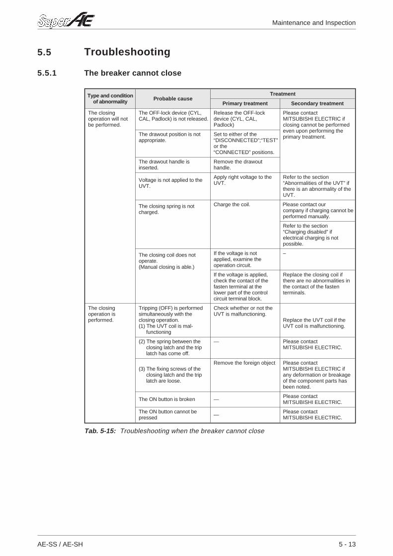
5.5 Troubleshooting
5.5.1 The breaker cannot close
AE-SS / AE-SH 5 - 13
Maintenance and Inspection
Type and conditionof abnormality Probable cause
Treatment
Primary treatment Secondary treatment
The closingoperation will notbe performed.
The OFF-lock device (CYL,CAL, Padlock) is not released.
Release the OFF-lockdevice (CYL, CAL,Padlock)
Please contactMITSUBISHI ELECTRIC ifclosing cannot be performedeven upon performing theprimary treatment.The drawout position is not
appropriate.Set to either of the“DISCONNECTED”;“TEST”or the“CONNECTED” positions.
The drawout handle isinserted.
Remove the drawouthandle.
Voltage is not applied to theUVT.
Apply right voltage to theUVT.
Refer to the section“Abnormalities of the UVT” ifthere is an abnormality of theUVT.
The closing spring is notcharged.
Charge the coil. Please contact ourcompany if charging cannot beperformed manually.
Refer to the section“Charging disabled” ifelectrical charging is notpossible.
The closing coil does notoperate.(Manual closing is able.)
If the voltage is notapplied, examine theoperation circuit.
–
If the voltage is applied,check the contact of thefasten terminal at thelower part of the controlcircuit terminal block.
Replace the closing coil ifthere are no abnormalities inthe contact of the fastenterminals.
The closingoperation isperformed.
Tripping (OFF) is performedsimultaneously with theclosing operation.(1) The UVT coil is mal-
functioning
Check whether or not theUVT is malfunctioning.
Replace the UVT coil if theUVT coil is malfunctioning.
(2) The spring between theclosing latch and the triplatch has come off.
— Please contactMITSUBISHI ELECTRIC.
(3) The fixing screws of theclosing latch and the triplatch are loose.
Remove the foreign object Please contactMITSUBISHI ELECTRIC ifany deformation or breakageof the component parts hasbeen noted.
The ON button is broken — Please contactMITSUBISHI ELECTRIC.
The ON button cannot bepressed — Please contact
MITSUBISHI ELECTRIC.
Tab. 5-15: Troubleshooting when the breaker cannot close
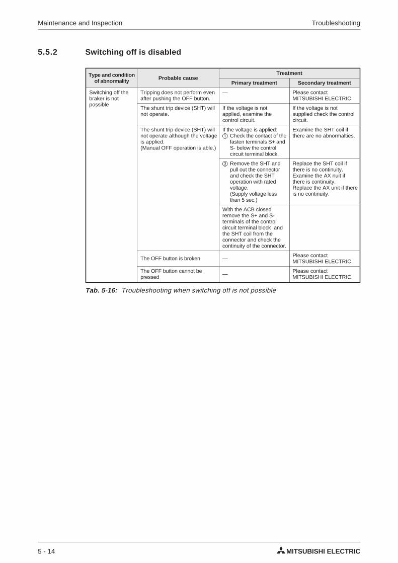
5.5.2 Switching off is disabled
5 - 14 MITSUBISHI ELECTRIC
Maintenance and Inspection Troubleshooting
Type and conditionof abnormality Probable cause
Treatment
Primary treatment Secondary treatment
Switching off thebraker is notpossible
Tripping does not perform evenafter pushing the OFF button.
— Please contactMITSUBISHI ELECTRIC.
The shunt trip device (SHT) willnot operate.
If the voltage is notapplied, examine thecontrol circuit.
If the voltage is notsupplied check the controlcircuit.
The shunt trip device (SHT) willnot operate although the voltageis applied.(Manual OFF operation is able.)
If the voltage is applied: Check the contact of the
fasten terminals S+ andS- below the controlcircuit terminal block.
Examine the SHT coil ifthere are no abnormalties.
Remove the SHT andpull out the connectorand check the SHToperation with ratedvoltage.(Supply voltage lessthan 5 sec.)
Replace the SHT coil ifthere is no continuity.Examine the AX nuit ifthere is continuity.Replace the AX unit if thereis no continuity.
With the ACB closedremove the S+ and S-terminals of the controlcircuit terminal block andthe SHT coil from theconnector and check thecontinuity of the connector.
The OFF button is broken — Please contactMITSUBISHI ELECTRIC.
The OFF button cannot bepressed — Please contact
MITSUBISHI ELECTRIC.
Tab. 5-16: Troubleshooting when switching off is not possible
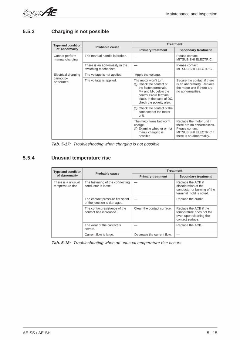
5.5.3 Charging is not possible
5.5.4 Unusual temperature rise
AE-SS / AE-SH 5 - 15
Maintenance and Inspection
Type and conditionof abnormality Probable cause
Treatment
Primary treatment Secondary treatment
Cannot performmanual charging.
The manual handle is broken. — Please contactMITSUBISHI ELECTRIC.
There is an abnormality in theswitching mechanism.
— Please contactMITSUBISHI ELECTRIC.
Electrical chargingcannot beperformed.
The voltage is not applied. Apply the voltage. —
The voltage is applied. The motor won´t turn. Check the contact of
the fasten terminals,M+ and M-, below thecontrol circuit terminalblock. In the case of DC,check the polarity also.
Secure the contact if thereis an abnormality. Replacethe motor unit if there areno abnormalities.
Check the contact of theconnector of the motorunit.
The motor turns but won´tcharge. Examine whether or not
manul charging ispossible
Replace the motor unit ifthere are no abnormalities.Please contactMITSUBISHI ELECTRIC ifthere is an abnormality.
Tab. 5-17: Troubleshooting when charging is not possible
Type and conditionof abnormality Probable cause
Treatment
Primary treatment Secondary treatment
There is a unusualtemperature rise
The fastening of the connectingconductor is loose.
— Replace the ACB ifdiscoloration of theconductor or burning of theterminal mold is noted.
The contact pressure flat sprintof the junction is damaged.
— Replace the cradle.
The contact resistance of thecontact has increased.
Clean the contact surface. Replace the ACB if thetemperature does not falleven upon cleaning thecontact surface.
The wear of the contact issevere.
— Replace the ACB.
Current flow is large. Decrease the current flow. —
Tab. 5-18: Troubleshooting when an unusual temperature rise occurs
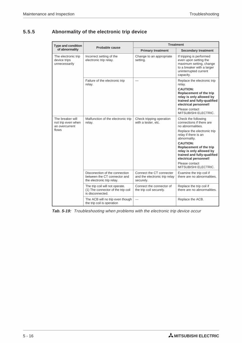
5.5.5 Abnormality of the electronic trip device
5 - 16 MITSUBISHI ELECTRIC
Maintenance and Inspection Troubleshooting
Type and conditionof abnormality Probable cause
Treatment
Primary treatment Secondary treatment
The electronic tripdevice tripsunnecessarily
Incorrect setting of theelectronic trip relay.
Change to an appropriatesetting.
If tripping is performedeven upon setting themaximum setting, changeto a breaker with a largeruninterrupted currentcapacity.
Failure of the electronic triprelay.
— Replace the electronic triprelay.
CAUTION:Replacement of the triprelay is only allowed bytrained and fully-qualifiedelectrical personnel!Please contactMITSUBISHI ELECTRIC.
The breaker willnot trip even whenan overcurrentflows
Malfunction of the electronic triprelay.
Check tripping operationwith a tester, etc.
Check the followingconnections if there areno abnormalities.
Replace the electronic triprelay if there is anabnormality.
CAUTION:Replacement of the triprelay is only allowed bytrained and fully-qualifiedelectrical personnel!Please contactMITSUBISHI ELECTRIC.
Disconection of the connectionbetween the CT connector andthe electronic trip relay.
Connect the CT connecterand the electronic trip relaysecurely.
Examine the trip coil ifthere are no abnormalities.
The trip coil will not operate.(1) The connector of the trip coilis disconnected.
Connect the connector ofthe trip coil securely.
Replace the trip coil ifthere are no abnormalities.
The ACB will no trip even thoughthe trip coil is operation
— Replace the ACB.
Tab. 5-19: Troubleshooting when problems with the electronic trip device occur
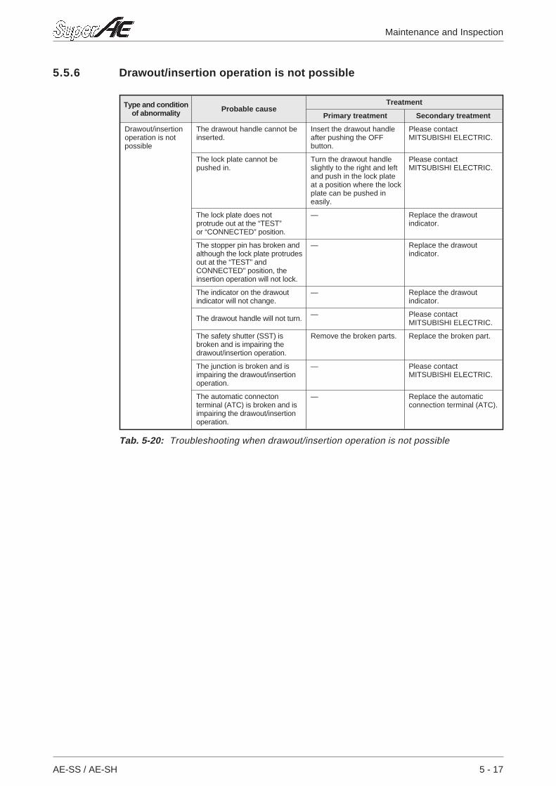
5.5.6 Drawout/insertion operation is not possible
AE-SS / AE-SH 5 - 17
Maintenance and Inspection
Type and conditionof abnormality Probable cause
Treatment
Primary treatment Secondary treatment
Drawout/insertionoperation is notpossible
The drawout handle cannot beinserted.
Insert the drawout handleafter pushing the OFFbutton.
Please contactMITSUBISHI ELECTRIC.
The lock plate cannot bepushed in.
Turn the drawout handleslightly to the right and leftand push in the lock plateat a position where the lockplate can be pushed ineasily.
Please contactMITSUBISHI ELECTRIC.
The lock plate does notprotrude out at the “TEST”or “CONNECTED” position.
— Replace the drawoutindicator.
The stopper pin has broken andalthough the lock plate protrudesout at the “TEST” andCONNECTED" position, theinsertion operation will not lock.
— Replace the drawoutindicator.
The indicator on the drawoutindicator will not change.
— Replace the drawoutindicator.
The drawout handle will not turn. — Please contactMITSUBISHI ELECTRIC.
The safety shutter (SST) isbroken and is impairing thedrawout/insertion operation.
Remove the broken parts. Replace the broken part.
The junction is broken and isimpairing the drawout/insertionoperation.
— Please contactMITSUBISHI ELECTRIC.
The automatic connectonterminal (ATC) is broken and isimpairing the drawout/insertionoperation.
— Replace the automaticconnection terminal (ATC).
Tab. 5-20: Troubleshooting when drawout/insertion operation is not possible
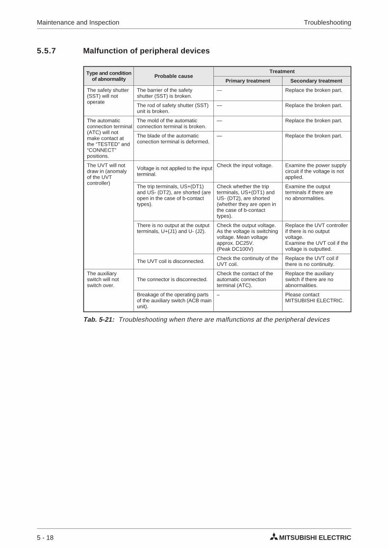
5.5.7 Malfunction of peripheral devices
5 - 18 MITSUBISHI ELECTRIC
Maintenance and Inspection Troubleshooting
Type and conditionof abnormality Probable cause
Treatment
Primary treatment Secondary treatment
The safety shutter(SST) will notoperate
The barrier of the safetyshutter (SST) is broken.
— Replace the broken part.
The rod of safety shutter (SST)unit is broken.
— Replace the broken part.
The automaticconnection terminal(ATC) will notmake contact atthe “TESTED” and“CONNECT”positions.
The mold of the automaticconnection terminal is broken.
— Replace the broken part.
The blade of the automaticconection terminal is deformed.
— Replace the broken part.
The UVT will notdraw in (anomalyof the UVTcontroller)
Voltage is not applied to the inputterminal.
Check the input voltage. Examine the power supplycircuit if the voltage is notapplied.
The trip terminals, US+(DT1)and US- (DT2), are shorted (areopen in the case of b-contacttypes).
Check whether the tripterminals, US+(DT1) andUS- (DT2), are shorted(whether they are open inthe case of b-contacttypes).
Examine the outputterminals if there areno abnormalities.
There is no output at the outputterminals, U+(J1) and U- (J2).
Check the output voltage.As the voltage is switchingvoltage. Mean voltageapprox. DC25V.(Peak DC100V)
Replace the UVT controllerif there is no outputvoltage.Examine the UVT coil if thevoltage is outputted.
The UVT coil is disconnected. Check the continuity of theUVT coil.
Replace the UVT coil ifthere is no continuity.
The auxiliaryswitch will notswitch over.
The connector is disconnected.Check the contact of theautomatic connectionterminal (ATC).
Replace the auxiliaryswitch if there are noabnormalities.
Breakage of the operating partsof the auxiliary switch (ACB mainunit).
– Please contactMITSUBISHI ELECTRIC.
Tab. 5-21: Troubleshooting when there are malfunctions at the peripheral devices
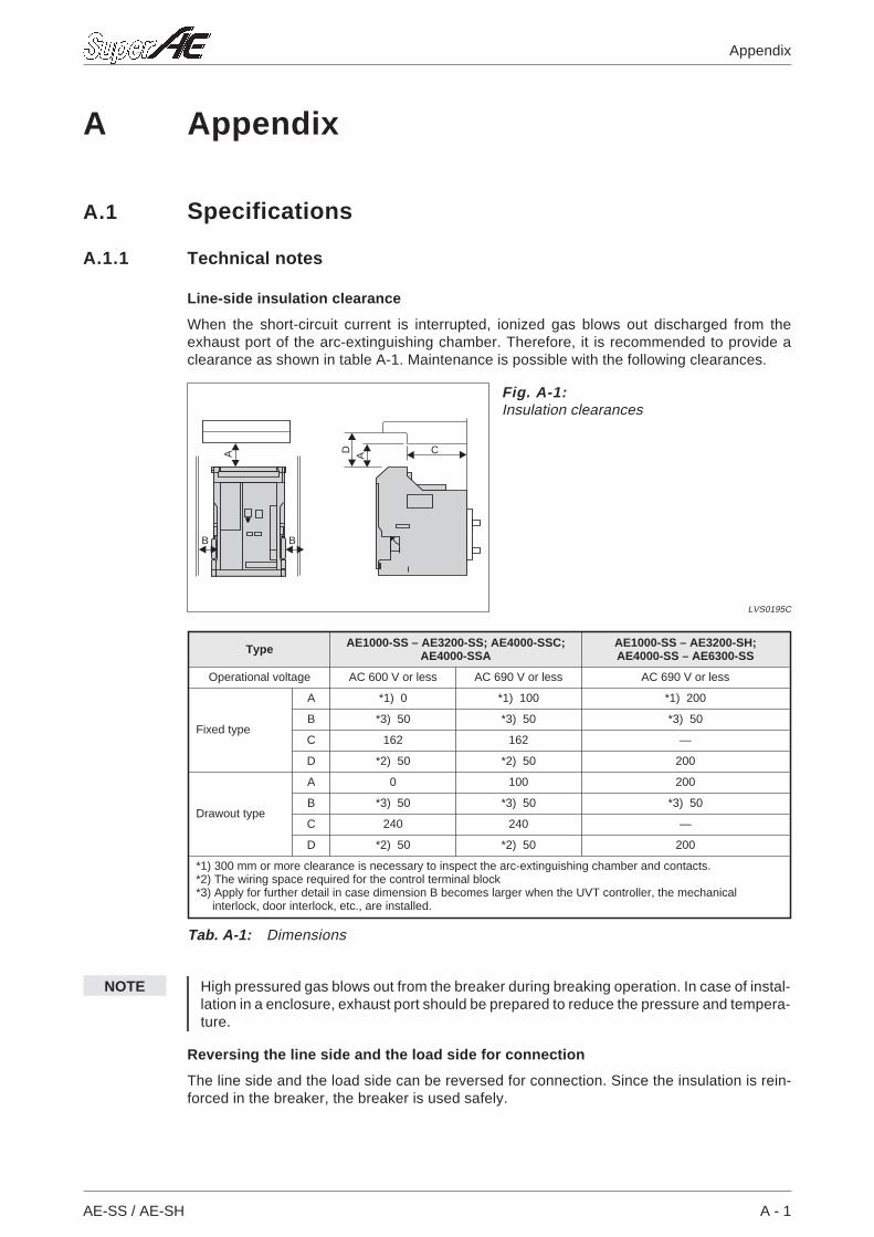
A Appendix
A.1 Specifications
A.1.1 Technical notes
Line-side insulation clearance
When the short-circuit current is interrupted, ionized gas blows out discharged from theexhaust port of the arc-extinguishing chamber. Therefore, it is recommended to provide aclearance as shown in table A-1. Maintenance is possible with the following clearances.
NOTE High pressured gas blows out from the breaker during breaking operation. In case of instal-lation in a enclosure, exhaust port should be prepared to reduce the pressure and tempera-ture.
Reversing the line side and the load side for connection
The line side and the load side can be reversed for connection. Since the insulation is rein-forced in the breaker, the breaker is used safely.
AE-SS / AE-SH A - 1
Appendix
BB
A CD A
Fig. A-1:Insulation clearances
LVS0195C
Type AE1000-SS – AE3200-SS; AE4000-SSC;AE4000-SSA
AE1000-SS – AE3200-SH;AE4000-SS – AE6300-SS
Operational voltage AC 600 V or less AC 690 V or less AC 690 V or less
Fixed type
A *1) 0 *1) 100 *1) 200
B *3) 50 *3) 50 *3) 50
C 162 162 —
D *2) 50 *2) 50 200
Drawout type
A 0 100 200
B *3) 50 *3) 50 *3) 50
C 240 240 —
D *2) 50 *2) 50 200
*1) 300 mm or more clearance is necessary to inspect the arc-extinguishing chamber and contacts.*2) The wiring space required for the control terminal block*3) Apply for further detail in case dimension B becomes larger when the UVT controller, the mechanical
interlock, door interlock, etc., are installed.
Tab. A-1: Dimensions
A.2 Operating conditions
A.2.1 Normal operating conditions
If the following normal standard working conditions are all met under ordinary conditions, theAE series air circuit breaker may be used unless otherwise specified.
Ambient air temperature
A range of max. +40°C to min. -5°C is recommended. However, the average over 24 hoursmust not exceed +35°C.
Altitude
2,000 m or less
Environmental conditions
The air must be clean, and the relative humidity should be 85 % or less at a maximum of +40 °C. 90% or less is acceptable at +20 °C.
Installation conditions
When installing the AE series air circuit breaker, refer to the installation instructions in the cata-logue and in the instruction manual.
A.2.2 Special operating conditions
In case of special operating conditions, modified air circuit breakers are available. Pleasespecify when ordering.
Special ambient temperature
If the ambient temperature exceeds +40 °C, the uninterrupted current rating will be reduced.The reduction value is given in tab. A-3.
Special environmental conditions
If the breaker is used at high termperatures and / or high humidity, the insulation durability andother electrical / mechanical features may deteriorate. Therefore, the breaker should be spe-cially treated. Moisture fungus treatment with increased corrosion-resistance is recom-mended.
Since some parts may pose problems due to corrosion in an environment where corrosive gasresults from corrosion, the increased extra-corrosion proof specification is recommended.
Special altitude
If the breaker is used at an altitude of 2,000 m or higher, the heat radiation rate is reduceddecreasing the operating voltage rating, continuous current capacity and breaking capacity.Moreover, the durability of the insulation is decreased owing to the atmospheric pressure.Apply for further details.
A - 2 MITSUBISHI ELECTRIC
Appendix Operating conditions
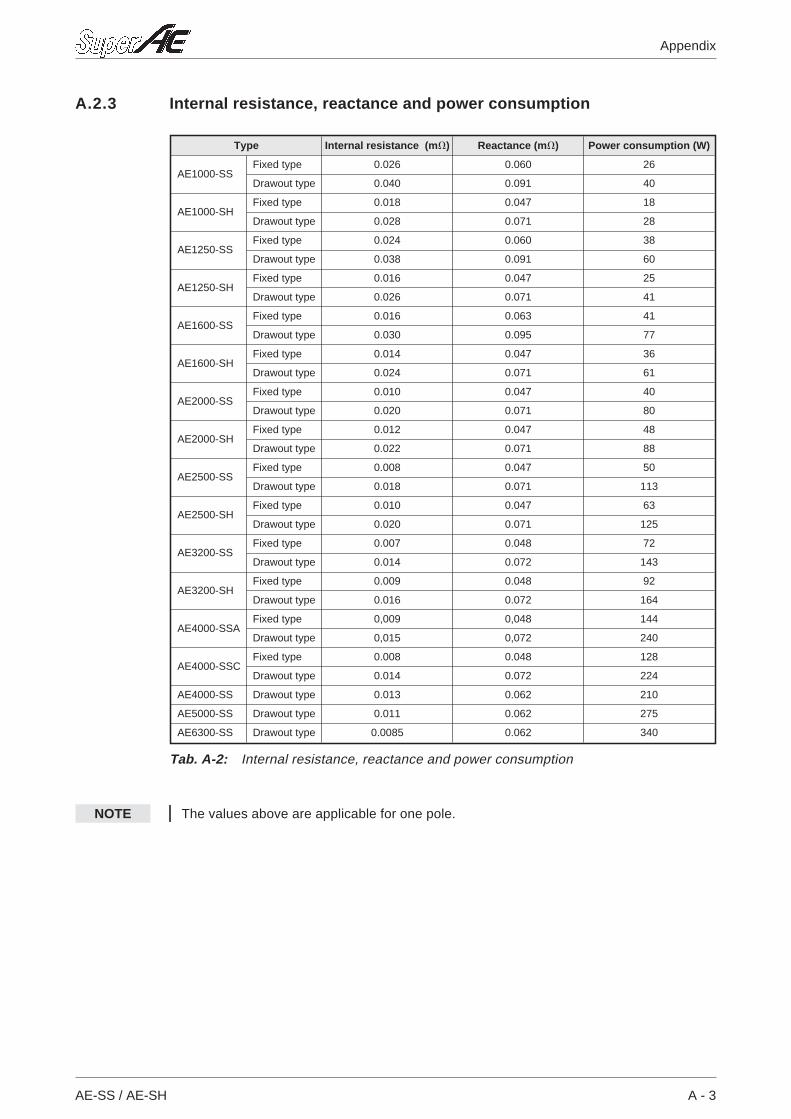
A.2.3 Internal resistance, reactance and power consumption
NOTE The values above are applicable for one pole.
AE-SS / AE-SH A - 3
Appendix
Type Internal resistance (m) Reactance (m) Power consumption (W)
AE1000-SSFixed type 0.026 0.060 26
Drawout type 0.040 0.091 40
AE1000-SHFixed type 0.018 0.047 18
Drawout type 0.028 0.071 28
AE1250-SSFixed type 0.024 0.060 38
Drawout type 0.038 0.091 60
AE1250-SHFixed type 0.016 0.047 25
Drawout type 0.026 0.071 41
AE1600-SSFixed type 0.016 0.063 41
Drawout type 0.030 0.095 77
AE1600-SHFixed type 0.014 0.047 36
Drawout type 0.024 0.071 61
AE2000-SSFixed type 0.010 0.047 40
Drawout type 0.020 0.071 80
AE2000-SHFixed type 0.012 0.047 48
Drawout type 0.022 0.071 88
AE2500-SSFixed type 0.008 0.047 50
Drawout type 0.018 0.071 113
AE2500-SHFixed type 0.010 0.047 63
Drawout type 0.020 0.071 125
AE3200-SSFixed type 0.007 0.048 72
Drawout type 0.014 0.072 143
AE3200-SHFixed type 0.009 0.048 92
Drawout type 0.016 0.072 164
AE4000-SSAFixed type 0,009 0,048 144
Drawout type 0,015 0,072 240
AE4000-SSCFixed type 0.008 0.048 128
Drawout type 0.014 0.072 224
AE4000-SS Drawout type 0.013 0.062 210
AE5000-SS Drawout type 0.011 0.062 275
AE6300-SS Drawout type 0.0085 0.062 340
Tab. A-2: Internal resistance, reactance and power consumption
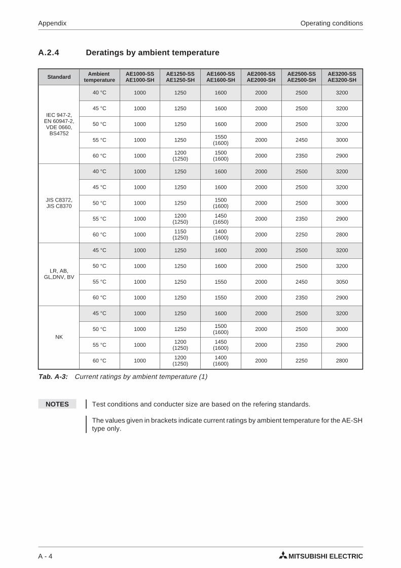
A.2.4 Deratings by ambient temperature
NOTES Test conditions and conducter size are based on the refering standards.
The values given in brackets indicate current ratings by ambient temperature for the AE-SHtype only.
A - 4 MITSUBISHI ELECTRIC
Appendix Operating conditions
Standard Ambienttemperature
AE1000-SSAE1000-SH
AE1250-SSAE1250-SH
AE1600-SSAE1600-SH
AE2000-SSAE2000-SH
AE2500-SSAE2500-SH
AE3200-SSAE3200-SH
IEC 947-2,EN 60947-2,VDE 0660,
BS4752
40 °C 1000 1250 1600 2000 2500 3200
45 °C 1000 1250 1600 2000 2500 3200
50 °C 1000 1250 1600 2000 2500 3200
55 °C 1000 1250 1550(1600) 2000 2450 3000
60 °C 1000 1200(1250)
1500(1600) 2000 2350 2900
JIS C8372,JIS C8370
40 °C 1000 1250 1600 2000 2500 3200
45 °C 1000 1250 1600 2000 2500 3200
50 °C 1000 1250 1500(1600) 2000 2500 3000
55 °C 1000 1200(1250)
1450(1650) 2000 2350 2900
60 °C 1000 1150(1250)
1400(1600) 2000 2250 2800
LR, AB,GL,DNV, BV
45 °C 1000 1250 1600 2000 2500 3200
50 °C 1000 1250 1600 2000 2500 3200
55 °C 1000 1250 1550 2000 2450 3050
60 °C 1000 1250 1550 2000 2350 2900
NK
45 °C 1000 1250 1600 2000 2500 3200
50 °C 1000 1250 1500(1600) 2000 2500 3000
55 °C 1000 1200(1250)
1450(1600) 2000 2350 2900
60 °C 1000 1200(1250)
1400(1600) 2000 2250 2800
Tab. A-3: Current ratings by ambient temperature (1)
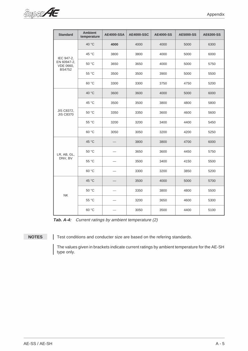
NOTES Test conditions and conducter size are based on the refering standards.
The values given in brackets indicate current ratings by ambient temperature for the AE-SHtype only.
AE-SS / AE-SH A - 5
Appendix
Standard Ambienttemperature AE4000-SSA AE4000-SSC AE4000-SS AE5000-SS AE6300-SS
IEC 947-2,EN 60947-2,VDE 0660,
BS4752
40 °C 4000 4000 4000 5000 6300
45 °C 3800 3800 4000 5000 6000
50 °C 3650 3650 4000 5000 5750
55 °C 3500 3500 3900 5000 5500
60 °C 3300 3300 3750 4750 5200
JIS C8372,JIS C8370
40 °C 3600 3600 4000 5000 6000
45 °C 3500 3500 3800 4800 5800
50 °C 3350 3350 3600 4600 5600
55 °C 3200 3200 3400 4400 5450
60 °C 3050 3050 3200 4200 5250
LR, AB, GL,DNV, BV
45 °C — 3800 3800 4700 6000
50 °C — 3650 3600 4450 5750
55 °C — 3500 3400 4150 5500
60 °C — 3300 3200 3850 5200
NK
45 °C — 3500 4000 5000 5700
50 °C — 3350 3800 4800 5500
55 °C — 3200 3650 4600 5300
60 °C — 3050 3500 4400 5100
Tab. A-4: Current ratings by ambient temperature (2)
A - 6 MITSUBISHI ELECTRIC
Appendix Operating conditions
A.3 Index
AE-SS / AE-SH A - 7
Appendix
INDEX
A
Accessories . . . . . . . . . . . . . . . . . . . . . . . . . . . 4-1
Advices for battery recycling. . . . . . . . . . . . . . 3-17
Auxiliary switch (AX) . . . . . . . . . . . . . . . . . . . . . 4-3
B
B type relay . . . . . . . . . . . . . . . . . . . . . . . . . . . . 3-8
C
Castell lock (CAL) . . . . . . . . . . . . . . . . . . . . . . 4-16
Cell switch (CL) . . . . . . . . . . . . . . . . . . . . . . . . 4-13
Characteristics setting. . . . . . . . . . . . . . . . . . . . 3-4
Charging operation . . . . . . . . . . . . . . . . . . . . . 2-25
Checking the trip characteristics. . . . . . . . . . . 3-14
Closing coil (CC) . . . . . . . . . . . . . . . . . . . . . . . . 4-6
Closing/opening operation . . . . . . . . . . . . . . . 2-27
Connections . . . . . . . . . . . . . . . . . . . . . . . . . . 2-18
Counter (CNT). . . . . . . . . . . . . . . . . . . . . . . . . 4-17
Cylinder lock (CYL) . . . . . . . . . . . . . . . . . . . . . 4-15
D
Dimensions . . . . . . . . . . . . . . . . . . . . . . . . . . . . 2-4
Door interlock (DI) . . . . . . . . . . . . . . . . . . . . . . 4-33
Drawout operation. . . . . . . . . . . . . . . . . . . . . . 2-29
E
Electrical operation . . . . . . . . . . . . . . . . . . . . . 2-28
Electromagnetic force . . . . . . . . . . . . . . . . . . . 2-20
Electronic trip relay . . . . . . . . . . . . . . . . . . . . . . 3-1
External view of breakers . . . . . . . . . . . . . . . . . 1-1
F
Field tester. . . . . . . . . . . . . . . . . . . . . . . . . . . . 3-14
Front terminal adapter (FTA) . . . . . . . . . . . . . 4-48
G
Guidelines for inspections. . . . . . . . . . . . . . . . . 5-5
H
Handling . . . . . . . . . . . . . . . . . . . . . . . . . . . . . . 2-2
I
Insert operation . . . . . . . . . . . . . . . . . . . . . . . . 2-30
Inspection . . . . . . . . . . . . . . . . . . . . . . . . . . . . . 5-1
Installation . . . . . . . . . . . . . . . . . . . . . . . . . . . . 2-13
Internal construction of breakers . . . . . . . . . . . 1-5
M
M type relay. . . . . . . . . . . . . . . . . . . . . . . . . . . . 3-6
Maintenance . . . . . . . . . . . . . . . . . . . . . . . . . . . 5-1
Manual operation . . . . . . . . . . . . . . . . . . . . . . 2-27
Mechanical interlock (MI) . . . . . . . . . . . . . . . . 4-28
Mis-insertion preventor (MIP) . . . . . . . . . . . . . 4-26
Motor charging device (MD) . . . . . . . . . . . . . . 4-10
O
Opening/closing operation . . . . . . . . . . . . . . . 2-27
Operating characteristics . . . . . . . . . . . . . . . . . 3-1
Operating conditions. . . . . . . . . . . . . . . . . . . . . A-2
Operating systems . . . . . . . . . . . . . . . . . . . . . 3-12
Operation. . . . . . . . . . . . . . . . . . . . . . . . . . . . . . 3-1
P
Push-button cover . . . . . . . . . . . . . . . . . . . . . . 4-47
S
S type relay . . . . . . . . . . . . . . . . . . . . . . . . . . . . 3-4
Safety lock kit . . . . . . . . . . . . . . . . . . . . . . . . . 4-20
Safety shutter (SST) . . . . . . . . . . . . . . . . . . . . 4-18
Setting example . . . . . . . . . . . . . . . . . . . . . . . 3-10
Shorting b-contact (SBC) . . . . . . . . . . . . . . . . 4-23
Shunt trip device (SHT). . . . . . . . . . . . . . . . . . . 4-5
Storage . . . . . . . . . . . . . . . . . . . . . . . . . . . . . . 2-12
A - 8 MITSUBISHI ELECTRIC
Appendix Index
T
Technical notes. . . . . . . . . . . . . . . . . . . . . . . . . A-1
Terminals. . . . . . . . . . . . . . . . . . . . . . . . . . . . . 2-24
Test jumper (TJ) . . . . . . . . . . . . . . . . . . . . . . . 4-40
Troubleshooting . . . . . . . . . . . . . . . . . . . . . . . 5-13
U
Undervoltage trip device (UVT) . . . . . . . . . . . . 4-7
Unpacking . . . . . . . . . . . . . . . . . . . . . . . . . . . . . 2-1
V
Vertical terminal adapter (VTA) . . . . . . . . . . . 4-49
W
Weight . . . . . . . . . . . . . . . . . . . . . . . . . . . . . . . 2-11
Wiring diagram . . . . . . . . . . . . . . . . . . . . . . . . 2-21
Y
Y-160 field tester . . . . . . . . . . . . . . . . . . . . . . . 3-15
Y-2000 field tester . . . . . . . . . . . . . . . . . . . . . . 3-18
Z
ZCT for load circuits/external . . . . . . . . . . . . . 4-43

MITSUBISHI ELECTRICGothaer Straße 8 Phone: +49 2102 486-7800 Fax: +49 2102 486-4069 www.mitsubishi-automation.deD-40880 Ratingen Hotline: +49 1805 000-765 [email protected] www.mitsubishi-automation.com
HEADQUARTERS
MITSUBISHI ELECTRIC EUROPEEUROPE B.V.German BranchGothaer Straße 8D-40880 RatingenPhone: 02102 / 486-0Fax: 02102 / 486-11 20e mail: [email protected] ELECTRIC FRANCEEUROPE B.V.25, Boulevard des BouvetsF-92741 Nanterre CedexPhone: +33 1 55 68 55 68Fax: +33 1 55 68 56 85e mail: [email protected] ELECTRIC ITALYEUROPE B.V.Italian BranchC.D. Colleoni - P. Perseo Ing. 2Via Paracelso 12I-20041 Agrate Brianza (MI)Phone: +39 (0) 39 / 60 53 1Fax: +39 (0) 39 / 60 53 312e mail: [email protected] ELECTRIC SPAINEUROPE B.V.Carretera de Rubí 76-80E-08190 Sant Cugat del Vallés(Barcelona)Phone: +34 9 3 / 565 3131Fax: +34 9 3 / 589 2948MITSUBISHI ELECTRIC UKEUROPE B.V.UK BranchTravellers LaneGB-Hatfield Herts. AL10 8 XBPhone: +44 (0) 1707 / 27 61 00Fax: +44 (0) 1707 / 27 86 95MITSUBISHI ELECTRIC JAPANCORPORATION8-12,1 chome, HARUMI CHUO-KU,Office Tower „Z“ 14 FTokyo 104-6212Phone: +81 3 6221 6060Fax: +81 3 6221 6075MITSUBISHI ELECTRIC USAAUTOMATION500 Corporate Woods ParkwayVernon Hills, Illinois 60061Phone: +1 (0) 847 / 478 21 00Fax: +1 (0) 847 / 478 22 83
EUROPEAN REPRESENTATIVES
Emac S.A. BELGIUMIndustrialaan 1B-1702 Groot-BijgaardenPhone: +32 (0) 2 / 481 02 11Fax: +32 (0) 2 / 481 03 01e mail: [email protected] CR d.o.o. CROATIADrvinje 63HR-10000 ZagrebPhone: +385 (0)1/ 36 67 140Fax: +385 (0)1/ 36 67 140e mail: —AutoCont . CZECHIAControl Systems s.r.oNemocnicni 12CZ-702 00 Ostrava 2Phone: +420 59 / 6152 111Fax: +420 59 / 6152 562e mail: [email protected] poulsen DENMARKindustri & automationGeminivej 32DK-2670 GrevePhone: +45 (0) 43 / 95 95 95Fax: +45 (0) 43 / 95 95 91e mail: [email protected] POWEL OY FINLANDBox 33FIN-04251 KeravaPhone: +358 (9) 274 6420Fax: +358 (9) 274 64141e mail: —Antonios Drepanias S.A. GREECE52, Arkadias Str.GR-12132 Peristeri, AthensPhone: +30 (10) 578 1599Fax: +30 (10) 578 1082e mail: [email protected] Automatika Kft. HUNGARY55, Harmat St.HU-1105 BudapestPhone: +36 (0)1 / 2605 602Fax: +36 (0)1 / 2605 602e mail: [email protected] ELECTRIC IRELANDEUROPE B.V. – Irish BranchWestgate Business ParkIRL-Dublin 24Phone: +353 (0) 1 / 419 88 00Fax: +353 (0) 1 / 419 88 90e mail: [email protected] UAB LITHUANIATinklu 29ALT-5300 PanevezysPhone: +370 (5) 582-728Fax: +370 (5) 582-729e mail: [email protected]
EUROPEAN REPRESENTATIVES
Imtech NETHERLANDSMarine & IndustrySluisjesdijk 155NL-3008 AB-RotterdamPhone: +31 (0) 10 / 487 19 11Fax: +31 (0) 10 / 487 16 92e mail: [email protected] AS NORWAYLeirvikasen 43BN-5020 BergenPhone: +47 55 50 60 00Fax: +47 55 50 60 01e mail: [email protected] Technology SP. z.o.o POLANDul. Sliczna 36PL-31-444 KrakówPhone: +48 (0) 12 / 632 28 85Fax: +48 (0) 12 / 632 47 82e mail: [email protected] Trading & Services srl ROMANIABd. Lacul Tei nr. 1 BRO-72301 Bucuresti 2Phone: +40 (0) 21 / 201 7147Fax: +40 (0) 21 / 201 7148e mail: [email protected] d.o.o. SLOVENIAStegne 11SI-1000 LjubljanaPhone: +386 (0) 1- 513 8100Fax: +386 (0) 1- 513 8170e mail: [email protected] Energy SWEDENComponents ABJärnvägsgatan 36S-434 24 KungsbackaPhone: +46 (0) 300 / 69 00 40Fax: +46 (0) 300 / 1 64 75e mail: [email protected] AG SWITZERLANDMühlentalstr. 136CH-8200 SchaffhausenPhone: +41 (0) 52 / 625 84 25Fax: +41 (0) 52 / 625 88 25e mail: [email protected] TURKEYDarülaceze Cad. No. 43 KAT. 2TR-80270 Okmeydani-IstanbulPhone: +90 (0) 212 / 320 1640Fax: +90 (0) 212 / 320 1649e mail: [email protected]
MIDDLE EAST REPRESENTATIVE
GINO INDUSTRIES LTD. ISRAEL26, Ophir streetIL-32235 HaifaPhone: +972 (0) 4 / 867 06 56Fax: +972 (0) 4 / 867 42 27e mail: [email protected]
EURASIAN REPRESENTATIVE
Avtomatika Sever RUSSIAKrapivnij Per. 5, Of. 402RUS-194044 St PetersburgPhone: +7 812 / 1183 238Fax: +7 812 / 3039 648e mail: [email protected] RUSSIAPromyshlennaya St. 42RUS-198099 St PetersburgPhone: +7 812 / 325 36 53Fax: +7 812 / 325 36 53e mail: [email protected] RUSSIARyazanskij Prospekt, 8a, Office 100RUS-109428 MoscowPhone: +7 095 / 232 - 0207Fax: +7 095 / 232 - 0327e mail: [email protected]
AFRICAN REPRESENTATIVE
CBI Ltd SOUTH AFRICAPrivate Bag 2016ZA-1600 IsandoPhone: +27 (0) 11 / 928 2000Fax: +27 (0) 11 / 392 2354e mail: [email protected]
LVS
-Prin
ted
inG
erm
any
12.0
2
MITSUBISHI ELECTRIC
INDUSTRIAL AUTOMATION