Embed Size (px)
Citation preview

NTIA REPORT 99-364
Lower Mississippi RiverVTS Frequency Survey
Robert L. SoleBrent Bedford
U.S. DEPARTMENT OF COMMERCEWilliam Daley, Secretary
Larry Irving, Assistant Secretaryfor Communications and Information
June 1999

This Page Intentionally Left Blank
This Page Intentionally Left Blank

ii
Executive Summary
The maritime mobile frequency band supports maritime communications worldwide. Appendix 18 of theITU Radio Regulations (RR) defines the channels of the maritime mobile service. These channels support a varietyof communication functions including: public correspondence, intership and ship-to-coast, coast- to-ship, portoperations, calling and various safety purposes. Safety functions include distress, search and rescue, ship movement,navigation (bridge-to-bridge) communications, and maritime safety information broadcasts. One type of service thatcan enhance these functions is called a Vessel Traffic Service (VTS). The VTS will enable ships and shore stationsto automatically transmit and receive information between themselves in coastal and port areas and inlandwaterways. Ships will also be able to automatically exchange information on the high seas. The ships and shorestations will be able to exchange data on ship size, speed, location, heading, cargo and other pertinent information,such as navigation hazards and pollution spills.
The Coast Guard plans to operate an Automatic Independent Surveillance (AIS) digital selective calling(DSC) based transponder system as part of the Ports and Waterways Safety System (PAWWS) in the lowerMississippi River. The service area for this Vessel Traffic Service (VTS) system ranges from a 20 mile radiusaround the sea buoy located at the mouth of the Southwest Pass entrance of the Mississippi River, to river mile 255above Baton Rogue.
In a VTS area served by a shore side monitor, the system requires at least one dedicated duplex marineVHF channel for digital data transmissions. One frequency of the duplex pair is used for transponder-to-basestation communications and is known as the A side of the channel. The other frequency of the duplex pair is usedfor base station-to-transponder communications and is known as the B side of the channel. Large VTS areas suchas the lower Mississippi River will require additional duplex channels for signal coverage and some type offrequency re-use plan. In areas not served by a VTS shore based monitor, a simplex channel is used for ship-to-ship operations. A report published by NTIA which has been coordinated with the maritime community, NTIA TR-343 “Assessment of Compatibility Between 25 and 12.5 kHz Channelized Marine VHF Radios” concludedthat a VTS like system could operate on interstitial channels as long as it was assigned frequencies in coordinatedareas, such as duplex channels allocated to public correspondence services. However, additional studies performedby NTIA for the Coast Guard and Radio Technical Commission for Maritime Services (RTCM) SpecialCommittee (SC)-117 have shown that the maritime mobile VHF band in the New Orleans is shared with numerousland mobile transmitters and NOAA VHF weather broadcasts. These transmitters are known to cause interferencein some VHF marine radios and may also interfere with AIS operations.
Therefore, to ensure that the VTS AIS system operates with a minimal amount of RF interference on itsVHF data links, the Coast Guard requested that NTIA survey the duplex public correspondence channels and theinterstitial channels between them for interference and evaluate their potential to be used as AIS data channels. Inaddition, the interstitial channels on the edge of the public correspondence channels were monitored for interference.Personnel from NTIA and the Institute of Telecommunication Sciences (ITS) performed shipboard tests August10-14, 1998 and shore based tests September 5-9, 1998 to complete these tasks.
The evaluation of the channels potential for use as AIS data channels was based on SINAD histographsand SINAD maps that were produced based on data collected during the tests. The histographs and SINAD mapsof the interstitial channels show that they have potential for use as AIS data channels. However, additional testsshould be conducted with crystal filters installed at each shore station which will provide the base stations receiver

iii
additional protection from adjacent channel radio operations. NTIA recommends that the Coast Guard develop a strategy for planning and coordinating, the use of the
interstitial and public correspondence channels for AIS operations, with the auction winners in each district that theCoast Guard intends to operate a VTS system. Furthermore, channels that are identified as possible VTS channelsshould be dedicated to AIS operations and not be shared with any other types of services or functions so that theVTS system can operate with a minimal amount of RF interference to enhance its safety and reliability.

iv
Table of Contents
Section 1. Introduction 1.1 Background . . . . . . . . . . . . . . . . . . . . . . . . . . . . . . . . . . . . . . . . . . . . . . . . . . . . . . . . 1-1 1.2 Test Objectives . . . . . . . . . . . . . . . . . . . . . . . . . . . . . . . . . . . . . . . . . . . . . . . . . . . . . 1-2 1.3 Test Procedures . . . . . . . . . . . . . . . . . . . . . . . . . . . . . . . . . . . . . . . . . . . . . . . . . . . . . 1-2 1.3.1 Ship Receive . . . . . . . . . . . . . . . . . . . . . . . . . . . . . . . . . . . . . . . . . . . . . . . . . . . . 1-3 1.3.2 Base Receive . . . . . . . . . . . . . . . . . . . . . . . . . . . . . . . . . . . . . . . . . . . . . . . . . . . . 1-5 Section 2. Test Results 2.1 Ship Receive Interstitial Channel Histographs . . . . . . . . . . . . . . . . . . . . . . . . . . . . 2-1 2.2 Base Receive Interstitial Channel Histographs . . . . . . . . . . . . . . . . . . . . . . . . . . . . 2-5 2.3 Ship Receive Interstitial Channel SINAD Maps . . . . . . . . . . . . . . . . . . . . . . . . . . . 2-7
Section 3 Conclusions and Recommendations . . . . . . . . . . . . . . . . . . . . . . . . . . . . . . . . . . 3-1
Appendix A: Ship Receive Interstitial Channel Histographs . . . . . . . . . . . . . . . . . . . . . . . A-1
Appendix B: Ship Receive Interstitial Channel SINAD Maps . . . . . . . . . . . . . . . . . . . . . . B-1
Appendix C: Base Receive Interstitial Channel Histographs . . . . . . . . . . . . . . . . . . . . . . . C-1

This Page Intentionally Left Blank
This Page Intentionally Left Blank

1-1
SECTION 1INTRODUCTION
1.1 BackgroundThe Coast Guard plans to operate an Automatic Independent Surveillance (AIS) Digital Selective Calling
(DSC) based transponder system as part of the Ports and Waterways Safety System (PAWWS) in the lowerMississippi River. The service area for this Vessel Traffic Service (VTS) system ranges from a 20 mile radiusaround the sea buoy located at the mouth of the Southwest Pass entrance of the Mississippi River to a point 20miles above Baton Rogue. The implementation of this system in the lower Mississippi river requires at least twodedicated duplex marine VHF channels for its operation with a channel re-use plan. The channels will be used totransmit digital data to/from transponder units and five base stations. These channels are needed to provide signalcoverage for ship-to-shore and shore-to-ship communications throughout the VTS operating area, including thoseareas not served by a shore side monitor for ship-to-ship operations. A VTS center located in New Orleans willcoordinate the flow of data to/from the base stations and display vessel information to Coast Guard watch standers.
The Coast Guard has obtained frequency assignments for five duplex channel pairs for use as AIS datachannels and five assignments for voice channels. However, the frequency pairs of the channel assignments usedfor the ship-to-shore and shore-to-ship duplex data channels are not in conformance with Appendix 18 of the ITURadio Regulations. Furthermore, the ship-to-shore side of the data channels are accessible by mariners for voicecommunications. Voice communications on both the ship-to-shore and shore-to-ship side of the data channels aredisruptive to AIS data transmissions. The data links will have a higher data packet throughput if the channels arenot accessible by mariners for voice communications and are not shared with other services. The interstitial channelslocated between the public correspondence channels are attractive for AIS operations for those reasons. They are“new” channels in the VHF band with a limited number of assignments on them.
A report published by NTIA which has been coordinated with the maritime community, NTIA TR-343“Assessment of Compatibility Between 25 and 12.5 kHz Channelized Marine VHF Radios” concluded thata VTS like system could operate on interstitial channels as long as it was assigned frequencies in coordinated areas,such as duplex channels allocated to public correspondence services. In the US duplex public correspondencechannels are licensed by the FCC to operate on marine channels 24, 25, 26, 27, 28, 84, 85, 86, and 87. Theinterstitial duplex channels are identified as 224, 225, 226, 227, 284, 285, 286, and 287. The border interstitialchannels are identified as 283 and 228. The FCC has auctioned channels 24 to 28 and the interstitial channels 224to 287.
The transponder transmit frequencies are identified as the “A” side of the duplex channel and are used forship-to-shore communications. The base stations transmit frequencies are identified as the “B” side of the duplexchannel and are used for shore-to-ship communications. The frequencies of these channels are shown in Table 1-1.A diagram of the system is shown in Figure 1-1.

1-2

1-3
Table 1-1Duplex Channel Frequencies
Duplex Transponder Base StationChannel Designation Transmit Frequency Transmit Frequency
(MHz) (MHz)A Side B Side
283 157.1875 161.7875 24 157.2000 161.8000
224 157.2125 161.8125 84 157.2250 161.8250 284 157.2375 161.8375 25 157.2500 161.8500 225 157.2625 161.8625 85 157.2750 161.8750 285 157.2875 161.8875 26 157.3000 161.9000 226 157.3125 161.9125 86 157.3250 161.9250 286 157.3375 161.9375 27 157.3500 161.9500 227 157.3625 161.9625 87 157.3750 161.9750 287 157.3875 161.9875 28 157.4000 162.0000
228 157.4125 162.0125
1.2 IntroductionNTIA TR-343 identified duplex interstitial channels as possible candidate frequencies for AIS data
channels. However, additional studies performed by NTIA for the Coast Guard have shown that the maritime VHFband in the New Orleans area is shared with land mobile transmitters operating under FCC Parts 22 and 90 Title47 Code of Federal Regulations. There are also high powered NOAA VHF weather broadcasts in the VTS servicearea. These transmitters generate interference in maritime VHF radio receivers operating in the New Orleans andBaton Rouge areas. This interference reduces the capability of the mariners to use channels in the band for theircommunication and safety functions. These same transmitters may also cause interference in the AIS transponderand base station receivers that operate in the band. Therefore, the AIS data channels should be carefully chosenso that the VTS transponders and base stations can operate with a minimal amount of radio interference. To helpchoose the AIS data channels, the Coast Guard requested that NTIA and ITS survey the A and B sides of thepublic correspondence channels and associated interstitial channels for interference and evaluate their potential usefor AIS operations. The interstitial channels that border the public correspondence channels were also monitoredfor interference. The methods and test set-ups that were used to accomplish these tasks are described in thesection 1.3 of this report.
1.3 Test ProceduresThe transponder receive side of each channel shown in Table 1-1 was monitored for interference onboard
a Coast Guard Auxiliary vessel during the week of August 10-14, 1998. The test area encompassed the length ofthe Mississippi river from the sea buoy at Southwest Pass to river mile 255 above Baton Rouge, Louisiana. Thechannels were monitored for interference with a fixed mount VHF radio that can operate its receiver in local and

1-4
distance modes. The sensitivity of the receiver for a 20 dB SINAD in local mode is about -107 dBm and in distancemode is about -117 dBm. The speed of the ship was kept under 15 mph so that the distance between consecutivemeasurements on the same frequency would be under 1 mile. A spectrum analyzer was also used during these teststo observe and record the electromagnetic environment.
The base station receive side of each channel shown in Table 1-1 was monitored for interference at eachof the five communication tower sites during October 5-9, 1998. This testing utilized the system receive antennalocated on the tower and the same fixed mount VHF radio that was used on the ship. However, because it wasanticipated that the base station receiver would not operate in local mode, measurements were only made with theVHF radio receiver set to distance mode.
1.3.1 Ship Receive Test ProceduresThe test set-up used to survey the transponder receive side of the channels in Table 1-1 is shown below
in Figure 1-1. It was computer controlled and sequentially monitored the B side of each channel for interferenceby measuring the radio receiver’s SINAD as the ship traversed the river. A DGPS receiver was used to note thelocation on the river where the SINAD measurement was made.
Figure 1-1Shipboard Test Set-up
The following steps were used to survey the selected channels for interference on the Mississippi River.
1. The equipment in Figure 1-1 was installed on the Coast Guard Auxiliary vessel.
2. The computer tuned the radio and test set to the selected channel via the serial port and IEEE 488 interface. Thecomputer also set the radio receiver to distance or local mode. Coax cable was used to connect a 10 foot whipantenna mounted on the flying bridge of the ship to the input of the first coupler.
3. The RF power output of the test set (which also functioned as the signal generator) was set by the computer toproduce a 20 dB SINAD without interference being present for the selected frequency. The modulating signal was

1-5
Figure 1-2Base Receive Test Set-up
a 1 kHz tone adjusted in amplitude to produce a 3 kHz signal deviation for 25 kHz channels and 2 kHz forinterstitial channels. The RF power was adjusted to produce a 20 dB SINAD for each channel when the step wasrepeated. The required RF power output for each channel’s 20 dB SINAD, for local and distance mode, waspreviously measured in the laboratory and stored in the computer.
4. The computer read the receiver SINAD value as measured by the test set with the ship’s antenna connected intothe circuit and the ship’s location using the DGPS receiver. The following parameters were recorded by thecomputer into a data file: channel #, SINAD, time, and location. If the SINAD was below 14 dB or more than 15minutes elapsed since the last spectrum sweep then, in addition to the above mentioned data, the computer alsoinstructed the spectrum analyzer to sweep the 150-168 MHz band and record the power and frequency of theemitters that were present.
5. The computer set the receiver to local mode and steps 3 and 4 were repeated.
6 The computer set the receiver to the next channel (listed in Table 1-1) and steps 2 through 5 were repeated.The measurements were conducted from 7:00 am to 6:00 p.m. to coincide with the peak land mobile
transmitter activity.
1.3.2 Base Receive Test ProceduresThe A side of the channels in Table 1-1 were monitored for interference using the test set-up shown in
Figure 1-2. The procedures used for this test set-up are outlined in the following paragraphs. In this test set-up, thebandpass filter of the RF cabinet at each communications site was used as a pre-selector for the DSC-500 radiothat was used for SINAD measurements.
The following steps were used to monitor the selected channels for interference at the base stations.
1. The equipment in Figure 1-2 was placed inside the communications equipment building at each high site.

1-6
2. The computer tuned the radio and the test set to the selected channel. The test set also functioned as the desiredsignal generator. The computer set the radio receiver to distance mode. Coax cable was used to connect the outputof the RF cabinet band pass filter to the input of the RF combiner.
3. The RF power output of the test set, which was connected to the other port of the RF combiner, was set by thecomputer to produce a 21 dB SINAD for the selected frequency without interference being present. Themodulating signal was a 1 kHz tone adjusted in amplitude to produce a 3 kHz signal deviation for 25 kHz channelsand 2 kHz for interstitial channels. The RF power was adjusted to produce a 21 dB SINAD for each channel whenthe step was repeated. The required RF power output for each channel’s 21 dB SINAD was previously measuredin the laboratory and stored in the computer.
4. The communications site antenna was connected into the circuit and the computer read the receiver SINADvalue as measured by the test set. The SINAD measurement was then stored in a data file. The channel wasmonitored for fifteen minutes. 5 The computer set the receiver to the next channel in Table 1-1 and steps three and four were repeated.
The measurements were conducted from 7:00 am to 6:00 p.m. to coincide with the peak land mobiletransmitter activity.

2-1
SECTION 2TEST RESULTS
2. Test ResultsSINAD histographs and SINAD maps have been produced based on the data collected during the tests.
Appendix A contains histographs for the ship receive side of each interstitial channel in Table 1-1 for the mobilereceiver operating in local and distance mode. Appendix B contains the SINAD maps for the transponder receive(B sides) of channels 228 and 283 for local and distance mode operation. Appendix C contains histographs for thebase station receive side of each interstitial channel in Table 1-1.
The system will most likely use interstitial channels for data communications once it achieves operationalstatus, therefore histographs and SINAD maps for the 25 kHz duplex channels shown in Table 1-1 are not includedin this report. However, data for the 25 kHz channels is archived and histographs and SINAD maps of the channelscan be produced if the need arises.
2.1 SINAD Histographs SINAD histographs can be used to determine which channels would be appropriate choices for AIS
services . They are a graphical representation of the percentage of time versus SINAD dB value. Histographs witha greater distribution of SINAD measurements to higher dB values for a higher percentage of time indicate that thechannel is less likely to have interference present and therefore be a good choice for AIS operations. Histographsthat show the major portions of the SINAD distributions above 16 dB indicate that the channel has good potentialfor AIS operations.
2.1 Ship Receive HistographsThe ship receive histographs give an indication of how well the B side of the channel would function as the
communications link from the base station to the transponder. Ship receive side histographs that show a highdistribution of SINAD values to high values for a greater percentage of time means that the transponder should beable to respond to base station commands and receive relayed text/data messages when using that side of thechannel.
Histographs of the ship receive side of interstitial channels 228 and 283 with the receiver set to local anddistance modes are shown below in Figures 2-1 through and 2-4. They are a summary of the SINADmeasurements that were taken as the ship traversed the length of the VTS service. SINAD measurements ofspecific segments of the river are represented by the SINAD maps shown in Appendix B.
The histographs for all of the interstitial channels in Table 1-1 are shown in Appendix A.
2-2
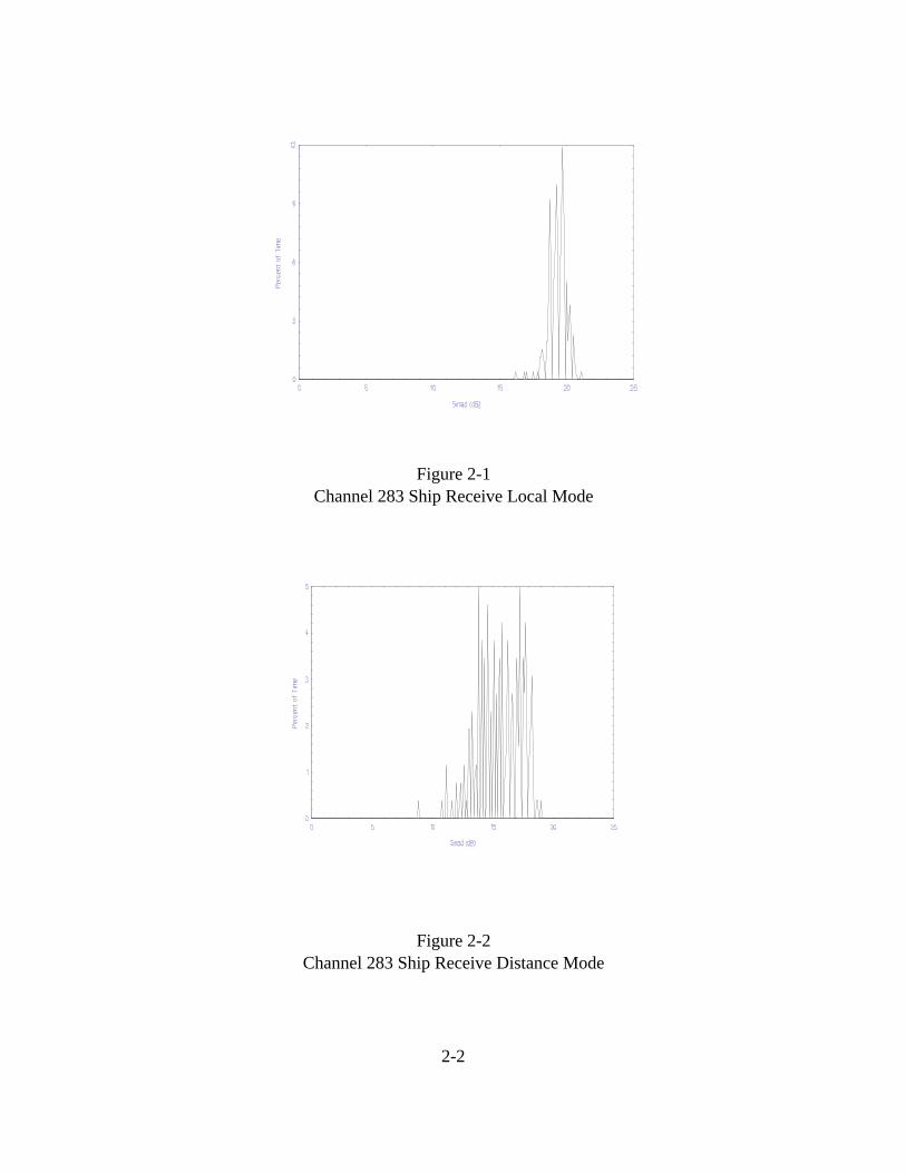
Figure 2-1Channel 283 Ship Receive Local Mode
Figure 2-2Channel 283 Ship Receive Distance Mode

2-3
Figure 2-3Channel 228 Ship Receive Local Mode
Figure 2-4Channel 228 Ship Receive Distance Mode

2-4
Figures 2-1 and 2-2 show that ship receive side of channel 283 may be a good choice for AIS operations.In local mode the major portion of the SINAD distributions are within the 17-21 dB range and for distance modethe major distribution is in the 14-18 dB range. Figures 2-3 and 2-4 show that the ship receive side of channel 228may also be a good choice for AIS operations for the same reasons. In local mode the major portion of the SINADdistribution is in the 19-22 dB range and 14-18 dB in distance mode. The system should have a high data/messagethroughput from the base station to the transponder using the B side of these channels because the SINAD valuesare generally above 16 dB with the receiver operating in local and distance mode. Therefore the base station totransponder link would function well on the B sides of channels 283 and 228 if the transponder receiver wereoperated in distance mode or local mode.
Reviewing the histographs in Appendix A of all the ship receive sides of the interstitial channels andcomparing the distribution of their SINAD measurements, it can be seen that the deviation of the SINADdistributions between the B sides of the interstitial channels is not significant. The major portion of the SINADdistributions for the B sides of the interstitial channels are in the 13-17 dB range for distance mode and 18-21 dBin local mode. Therefore, the B side of each channel has the potential to be used as an AIS data channel for thebase station to transponder link.
2.1 Base Receive HistographsHistographs of the base receive side of the channels give an indication of how well the A side of the channel
would function as the link from the transponder to the base station. Histographs of the base receive sides of thechannels with a greater distribution of SINAD measurements above 16 dB means that the base station should beable to receive a high percentage of the transponder position reports and text messages using that channel.Histographs of the base receive side of the channels with a greater distribution of SINAD measurements to lowvalues means that interference on this side of the duplex channel could disrupt the communications link from thetransponders to base stations, causing the base station receiver to miss transponder position reports, text messages,and command acknowledgments.
Histographs of the base receive sides of the interstitial channels in Appendix C are a combination of themeasurements taken at the five communication sites for each frequency represented as one graph. The histographswere prepared this way because three of the five sites will use one frequency and the other two sites will use theother one. Data is available to produce histographs for all channels at each site. For example, the histograph forthe base receive side of channel 283 shown below in Figure 2-5 was made from measurements taken of the A sideof that channel at each site averaged together. This histograph can be used to evaluate the potential for the basereceive side of the channel 283 for AIS operations throughout the entire VTS service area. The histographs for thebase receive sides of channels 228 and 283 are shown below in Figures 2-5 and 2-6. Histographs for the basereceive side of these channels were made only in distance mode. It is not anticipated that the base station receiverwill operate in local mode.

2-5
Figure 2-5Channel 283 Base Receive Histograph
Figure 2-6Channel 228 Base Receive Histograph
Figures 2-5 and 2-6 show that the A side of channels 283 and 228 should be further investigated forsuitability as the link from the transponders to the base stations. The addition of crystal filters, which would beinstalled at each base station for each operational frequency, would give the base station receiver additionalprotection against adjacent tuned transmitters. The additional protection should shift the SINAD distribution tohigher values for a greater percentage of time which would make the channel more attractive for AIS data ship-to-shore channel operations.

2-6
However it should be noted that this only applies to the interstitial channels. The crystal filters would notoffer any protection against on-tune transmitters. Marine VHF radios, at this time, do not allow operators to tuneto interstitial channels. Therefore, on-tune voice interference from marine VHF radios should not be a problem onthis side of the data channel if it is operating on interstitial channels, unlike the channels that are currently being used.
2.1 Ship Receive SINAD MapsSINAD maps for the ship receive side of the interstitial channels were produced based on the SINAD
measurements taken on the river. A DGPS receiver was used to note the location of the vessel on the river wheneach SINAD measurement was made. By combining the ship’s location and the SINAD measurement along withthe channel designation, color coded maps of the B side of each interstitial channel were made. Each measurementpoint is a segment on the river. The maps can be used to evaluate the B side of each interstitial channels potentialfor use as the base station to transponder link for AIS operations. In addition, the maps can be used as a tool topredict possible interference for specific locations on the river and how well the receiver would operate in local anddistance mode. The maps are color coded to represent SINAD levels as shown below in Table 2-1. Also includedin the table is an estimation of the message throughput for that SINAD level. As Table 2-1 indicates, violet is thebest color. Segments of the river that are colored violet should have above a 90 percent message throughput fromthe base station to the transponder for a ship operating in that part of the river.
Table 2-1
SINAD Value (dB) Color Message Throughput
0-3.9 red not functional4-7.9 yellow #30 % 8-11.9 green #70 % 12-15.9 blue #80 %<16 violet $90 %
SINAD maps for the ship receive sides of channels 228 and 283 for the receiver operating in local anddistance modes are shown in Appendix B. The map for the receiver operating in distance mode on channel 228(see pages B-2 to B-4) shows that many segments of the river are colored blue and green near New Orleans andBaton Rouge with one yellow segment near downtown Baton Rouge. This indicates that the receiver wasexperiencing a moderate amount of interference in the New Orleans and Baton Rouge areas on channel 228 inthose segments of the river while it was operating in distance mode. This interference may cause the AIStransponder only to receive about 70 percent of the base station commands and other ships broadcasts if it wereoperating on that channel in those sections of the river. The map also shows that the river has mostly violet coloredsegments down river from New Orleans which indicates that the interference is significantly less in those segmentsof the river and that the transponder should receive almost all of the base station commands. With the receiver setto local mode for channel 228 (see pages B-5 to B-7), all but two segments of the river are colored violet. Thisindicates that if the AIS transponder were operated in local mode while using channel 228 that the interferenceshould not affect its ability to receive base station commands and re-broadcasted ships position reports throughthe entire VTS service area.

2-7
The map for the receiver operating in distance mode on channel 283 (see pages B-8 to B-10) shows thatmost of the segments of the river are colored blue near New Orleans and Baton Rouge with mostly violet segmentspast New Orleans. There are a few green segments in the New Orleans and Baton Rouge areas. This indicates thatthe receiver was experiencing some interference in the New Orleans and Baton Rouge areas on channel 283 inthose segments of the river. The interference may cause the AIS transponder to miss a few of the base stationcommands and re-broadcasted ship’s position data.
The map for channel 283 in distance mode also shows that the river has mostly violet colored segmentsdown river from New Orleans with one green segment near Pilot town. This indicates that the interference shouldnot cause the transponder to miss receiving base station commands and ships position reports in those segmentsof the river. With the receiver set to local mode for channel 283 (see pages B-11 to B-13), all but two segmentsof the river are colored violet. Those two segments are colored gray meaning that no measured data was collectedfor those segments. This indicates that if the AIS transponder were operated in local mode while using channel 283that the interference should not affect its ability to receive base station commands and re-broadcasted ships positionreports through the entire VTS service area.
Overall, for the receiver operating in distance mode, channel 283 shows better promise for AIS operations.It has more segments of the river colored violet than channel 228 which indicates that the interference has less ofan effect on that channel. In local mode operation, the two channels are equal with respect to possible use as AISdata channels. Both channels show violet segments of the river from Baton Rouge to the sea buoy indicating thatthe interference should not affect base station to transponder communications. However, operation of thetransponders in local mode assumes that the base station transmitters have sufficient signal coverage for a highmessage throughput.

This Page Intentionally Left Blank
This Page Intentionally Left Blank

3-1
SECTION 3CONCLUSIONS AND RECOMMENDATIONS
The following conclusions can be drawn based on the results of these tests:
1. Histographs of the ship receive sides of the interstitial channels between the public correspondencechannels show a high distribution of SINAD values above 16 dB, which indicates that the B sides of the interstitialchannels have the potential for use as AIS data channels for shore-to-ship communications in the lower MississippiRiver vessel traffic service area.
2. The distribution of the SINAD measurements for the ship receive interstitial channel histographs wasgreatest when the receiver was operated in local mode.
3. Histographs of the base receive sides of the interstitial channels between the public correspondencechannels show some SINAD distributions above 16 dB. These results indicate that, pending additional testing withcrystal filters, the A sides of the interstitial channels have the potential for use as AIS data channels for ship-to-shore communications in the lower Mississippi River vessel traffic service area.
4. SINAD maps of the ship receive side of the interstitial channels 228 and 283 shows that if thetransponder is operated in distance mode while using those channels, that RF interference in the New Orleans andBaton Rouge areas of the river may reduce the ability of the transponder to receive base station commands, textmessages, and other transponders relayed position reports. This interference would have the same effect if thetransponder were using the interstitial channels between the public correspondence channels as well.
5. SINAD maps of the ship receive side of the interstitial channels 228 and 283 shows that if thetransponder is operated in local mode while using those channels, that the RF interference to transponders in theNew Orleans and Baton Rouge areas of the river should be greatly reduced. This would also apply if thetransponder were using the interstitial channels between the public correspondence channels as well.
NTIA recommends that when the Coast Guard chooses duplex AIS data channels they:
1. Develop a strategy for planning and coordinating the use of the interstitial channels, located between thepublic coast station channels, for AIS data channels with the auction winners in each district that the Coast Guardintends to operate a VTS.
2. Select candidates for AIS data channels that could be dedicated to AIS operations and not be sharedwith any other types of services or functions, so that the VTS system operates with a minimal amount of RFinterference and its safety and reliability is enhanced.

3-2
3. Further investigate the interstitial channels potential for use as AIS data channels in the lower MississippiRiver vessel traffic service area through additional testing with crystal filters (tuned to the appropriate channels)installed at the base stations before the operational channels are chosen.
4. Choose AIS data channels and a re-use plan that limits the exposure of the transponder receiver toNOAA VHF weather broadcasts in Baton Rouge, New Orleans, and Buras. Transponders used in those sectorsof the VTSA should be operated on channels that have the greatest frequency separation between the NOAAweather broadcasts and the shore-to-ship side of the data channel.
5. Operate the AIS transponder receiver in local mode at all times, if there is sufficient desired signal coverage.

Appendix AShip Receive Interstitial Channel
SINAD Histographs

A-2
Figure A-1Channel 283 Local Mode
Figure A-2Channel 283 Distance Mode

A-3
Figure A-3Channel 224 Local Mode
Figure A-4Channel 224 Distance Mode

A-4
Figure A-5Channel 284 Local Mode
Figure A-6Channel 284 Distance Mode

A-5
Figure A-7Channel 225 Local Mode
Figure A-8Channel 225 Distance Mode

A-6
Figure A-9Channel 285 Local Mode
Figure A-10Channel 285 Distance Mode

A-7
Figure A-11Channel 226 Local Mode
Figure A-12Channel 226 Distance Mode

A-8
Figure A-13Channel 286 Local Mode
Figure A-14Channel 286 Distance Mode

A-9
Figure A-15Channel 227 Local Mode
Figure A-16Channel 227 Distance Mode

A-10
Figure A-17Channel 287 Local Mode
Figure A-18Channel 287 Distance Mode

A-11
Figure A-19Channel 228 Local Mode
Figure A-20Channel 228 Distance Mode

This Page Intentionally Left Blank
This Page Intentionally Left Blank

B-1
Appendix BShip Receive SINAD Maps
Each color corresponds to a SINAD value for that segment of the river.

B-2
Channel 228 Ship Receive Distance Mode

B-3
Channel 228 Ship Receive Distance Mode

B-4
Channel 228 Ship Receive Distance Mode

B-5
Channel 228 Ship Receive local Mode

B-6
Channel 228 Ship Receive local Mode

B-7
Channel 228 Ship Receive local Mode

B-8
Channel 283 Ship Receive Distance Mode

B-9
Channel 283 Ship Receive Distance Mode

B-10
Channel 283 Ship Receive Distance Mode

B-11
Channel 283 Ship Receive Local Mode

B-12
Channel 283 Ship Receive Local Mode

B-13
Channel 283 Ship Receive Local Mode

This Page Intentionally Left Blank
This Page Intentionally Left Blank

C-1
Appendix CBase Receive Interstitial Channel
SINAD Histographs
The Histographs for the base receive interstitial channels are based on the combined measurementsat each communication high site.

C-2
Figure C-1Channel 224 Base Receive
Figure C-2Channel 284 Base Receive

C-3
Figure C-3Channel 225 Base Receive
Figure C-4Channel 285 Base Receive

C-4
Figure C-5Channel 226 Base Receive
Figure C-6Channel 286 Base Receive

C-5
Figure C-7Channel 227 Base Receive
Figure C-8Channel 287 Base Receive

C-6
Figure C-9Channel 228 Base Receive
Figure C-10Channel 283 Base Receive


![Administering Cisco VTS · admin@VTS-A:~$ sudo su [sudo] password for admin: Step2 SourcetheVTSenvironment. root@VTS-A:# source /etc/profile.d/ncs.sh Step3 VerifyVTSstatus. root@VTS-A:#](https://img.pdfslide.net/doc/110x75/5ec8e3d704a90406890d6ec6/administering-cisco-vts-adminvts-a-sudo-su-sudo-password-for-admin-step2.jpg)