1
burner base. Converting the Bake Burner 1. Remove oven racks and oven support. 2. Remove oven bottom. 3. Remove screws securing bake igniter to bake burner. 4. Remove screws securing bake burner shield to oven burner box. 5. Remove screws securing bake burner to oven burner box. 6. Loosen air shutter screw and adjust opening on burner to 3/8” and tighten air shutter screw. 7. Remove orifice by turning counterclockwise and replace with orifice from bag labeled 1.68. Important: The orifice tip must be located 3/16” inside the burner for proper gas mixture and combustion. The depth of the orifice can be adjusted by turning the orifice counterclockwise (more depth) or clockwise (less depth). Reverse procedure as needed to reassemble. Converting the Broil Burner 1. Remove the screws (4) from the broiler baffle. 2. Carefully remove the broiler burner Note: Pay close attention to the igniter wire while removing the broiler burner. 3. Disconnect the igniter wire. 4. Use a 1/2” wrench to remove the broiler burner natural gas orifice hood and replace with LP broiler burner hood # 1.03. 5. Reinstall the converted broiler burner by first firmly attaching the igniter wire. 6. Reposition the broiler burner in its original position. 7. Replace the four screws into the broiler baffle. Air Shutter Settings for Broiler Burner 1. Use a screwdriver to loosen the air shutter screw. 2. Adjust the air shutters for LP gas by rotating the shutter to the fully open position. Your final settings may vary. 3. Retighten the air shutter screw. Bake and broiler flame must be checked with the door closed to properly check flame characteristics. 4. Turn on the gas. 5. Turn on the electricity. 6. Retighten the air shutter screw. 7. Turn on the bake and broiler burner. 8. As you watch the flame with the oven door closed, check the following through the oven door window: a. If the flames are yellow, open the air shutter more. b. If the flames blow away or flutter from the burner, close the air shutter more. 9. Open the oven door and check the inner cone of the bake and broiler burner flame. It should be approximately 1/2” to 3/4” long for the bake and broil burners. The combustion quality of the burner flames needs to be determined visually. With LP gas, some yellow tipping on the outer cones is normal. 10. When all adjustments are made and the results are satisfactory then replace the oven bottom cover. In some cases, foreign particles in the gas line may cause an orange flame at first but this will soon disappear. Note: To convert the oven back to Natural gas, reverse the instructions given for making the LP gas adjustments. Note: When the LP/Propane conversion is finished, complete the enclosed conversion label and place it next to the rating label. LP Conversion Kit Instructions (cont.) WARNING If you attempt to measure the inner cone of the flame, please use caution as burns could result. F21302A EN (041014) VIKING RANGE, LLC 111 Front Street • Greenwood, Mississippi 38930 USA • (662) 455-1200 The pressure regulator and the burner orifices are set for Natural gas. To use Liquid Propane gas, the regulator and burner orifices must be converted. To convert the range to LP gas, follow these instructions: 1. Disconnect all electrical power at the main circuit breaker or fuse box. 2. Shut off the gas supply to the range by closing the manual shut-off valve. Converting the Pressure Regulator 1. Locate the pressure regulator which can be found on the back of the range on the right hand side if facing the back of the range. 2. Unscrew the hex nut cap from the top of the regulator. 3. Unsnap the plastic plunger from the hex nut. 4. Reverse the plunger and reinstall onto the hex nut by pressing firmly. Note: Plunger is marked “Nat” and “LP”. Converted fuel type will be shown on the lower portion of the plunger. Converting the Surface Burners 1. Remove the top grates, burner caps, and burner heads. 2. Using a 9/32” or 7 mm nut driver remove the top burner orifices. These may be accessed through the opening in the burner base. Note: Save these orifices for future conversion back to Natural gas, if required. 3. Locate the proper LP surface burner orifices included with the kit according to the chart below. 4. Install the orifices in their correct location. To prevent leakage, make sure the orifice spuds are securely screwed into the WARNING The conversion must be performed by a qualified installer or gas supplier in accordance with the manufacturer’s instructions and all codes and requirements of the authority having jurisdiction. Failure to follow ALL instructions could result in serious injury or property damage. The qualified agency performing this work assumes responsibility for this conversion. Burner BTU Rate Orifice Size Left front (dual) High Low 15,800 1,000 1.09 0.33 Left rear 6,500 0.79 Center 8,000 0.87 Right front 15,000 1.19 Right rear 11,000 1.01 Bake 30,000 1.68 Broil 14,500 1.03 LP Conversion Kit Instructions for D3/3 Series Gas Self Clean and Dual Fuel Range Burner BTU Rate Orifice Size Left front 15,800 1.19 Left rear 6,500 0.79 Center 8,000 0.87 Right front 15,000 1.19 Right rear 11,000 1.01 Bake 30,000 1.68 Broil 14,500 1.03 D3 300 Series

LP Conversion Kit Instructions for D3/3 Series Gas Self ... · LP Conversion Kit Instructions for D3/3 Series Gas Self Clean and Dual Fuel Range Burner BTU Rate Orifice Size Left

  • Upload
    ngocong

  • View
    220

  • Download
    0

Embed Size (px)

Citation preview

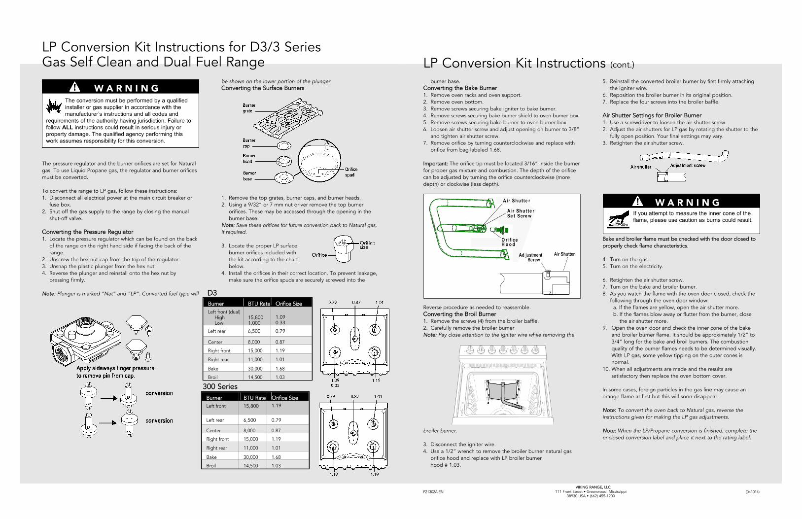
burner base.Converting the Bake Burner1. Remove oven racks and oven support.2. Remove oven bottom.3. Remove screws securing bake igniter to bake burner.4. Remove screws securing bake burner shield to oven burner box.5. Remove screws securing bake burner to oven burner box.6. Loosen air shutter screw and adjust opening on burner to 3/8”

and tighten air shutter screw.7. Remove orifice by turning counterclockwise and replace with

orifice from bag labeled 1.68.

Important: The orifice tip must be located 3/16” inside the burnerfor proper gas mixture and combustion. The depth of the orificecan be adjusted by turning the orifice counterclockwise (moredepth) or clockwise (less depth).

Reverse procedure as needed to reassemble.Converting the Broil Burner1. Remove the screws (4) from the broiler baffle.2. Carefully remove the broiler burnerNote: Pay close attention to the igniter wire while removing the

broiler burner.

3. Disconnect the igniter wire.4. Use a 1/2” wrench to remove the broiler burner natural gas

orifice hood and replace with LP broiler burnerhood # 1.03.

5. Reinstall the converted broiler burner by first firmly attachingthe igniter wire.

6. Reposition the broiler burner in its original position.7. Replace the four screws into the broiler baffle.

Air Shutter Settings for Broiler Burner1. Use a screwdriver to loosen the air shutter screw.2. Adjust the air shutters for LP gas by rotating the shutter to the

fully open position. Your final settings may vary.3. Retighten the air shutter screw.

Bake and broiler flame must be checked with the door closed toproperly check flame characteristics.

4. Turn on the gas.5. Turn on the electricity.

6. Retighten the air shutter screw.7. Turn on the bake and broiler burner.8. As you watch the flame with the oven door closed, check the

following through the oven door window:a. If the flames are yellow, open the air shutter more.b. If the flames blow away or flutter from the burner, close

the air shutter more.9. Open the oven door and check the inner cone of the bake

and broiler burner flame. It should be approximately 1/2” to3/4” long for the bake and broil burners. The combustionquality of the burner flames needs to be determined visually.With LP gas, some yellow tipping on the outer cones isnormal.

10. When all adjustments are made and the results aresatisfactory then replace the oven bottom cover.

In some cases, foreign particles in the gas line may cause anorange flame at first but this will soon disappear.

Note: To convert the oven back to Natural gas, reverse theinstructions given for making the LP gas adjustments.

Note: When the LP/Propane conversion is finished, complete theenclosed conversion label and place it next to the rating label.

LP Conversion Kit Instructions (cont.)

W A R N I N GIf you attempt to measure the inner cone of theflame, please use caution as burns could result.

F21302A EN (041014)VIKING RANGE, LLC

111 Front Street • Greenwood, Mississippi38930 USA • (662) 455-1200

The pressure regulator and the burner orifices are set for Naturalgas. To use Liquid Propane gas, the regulator and burner orificesmust be converted.

To convert the range to LP gas, follow these instructions:1. Disconnect all electrical power at the main circuit breaker or

fuse box.2. Shut off the gas supply to the range by closing the manual

shut-off valve.

Converting the Pressure Regulator1. Locate the pressure regulator which can be found on the back

of the range on the right hand side if facing the back of therange.

2. Unscrew the hex nut cap from the top of the regulator.3. Unsnap the plastic plunger from the hex nut.4. Reverse the plunger and reinstall onto the hex nut by

pressing firmly.

Note: Plunger is marked “Nat” and “LP”. Converted fuel type will

be shown on the lower portion of the plunger.Converting the Surface Burners

1. Remove the top grates, burner caps, and burner heads.2. Using a 9/32” or 7 mm nut driver remove the top burner

orifices. These may be accessed through the opening in theburner base.

Note: Save these orifices for future conversion back to Natural gas,if required.

3. Locate the proper LP surfaceburner orifices included withthe kit according to the chartbelow.

4. Install the orifices in their correct location. To prevent leakage,make sure the orifice spuds are securely screwed into the

W A R N I N GThe conversion must be performed by a qualifiedinstaller or gas supplier in accordance with themanufacturer’s instructions and all codes and

requirements of the authority having jurisdiction. Failure tofollow ALL instructions could result in serious injury orproperty damage. The qualified agency performing thiswork assumes responsibility for this conversion.

Burner BTU Rate Orifice SizeLeft front (dual)

HighLow

15,8001,000

1.090.33

Left rear 6,500 0.79

Center 8,000 0.87

Right front 15,000 1.19

Right rear 11,000 1.01

Bake 30,000 1.68

Broil 14,500 1.03

LP Conversion Kit Instructions for D3/3 Series Gas Self Clean and Dual Fuel Range

Burner BTU Rate Orifice SizeLeft front 15,800 1.19

Left rear 6,500 0.79

Center 8,000 0.87

Right front 15,000 1.19

Right rear 11,000 1.01

Bake 30,000 1.68

Broil 14,500 1.03

D3

300 Series