Embed Size (px)
Citation preview

LP Dimming Panels
® SPECIF ICAT ION SUBMITTAL Page
Job Name:
Job Number:
Model Numbers:
GRAFIK Systems® Power Equipment
369344c 1 04.28.2014
LP Dimming PanelsLP dimming panels are ideal for projects with many small loads. Each panel provides power and dimming for up to 32 dimming legs.
Features• Works directly with incandescent, magnetic
low‑voltage, and neon/cold cathode lighting, as well as Lutron® TuWire® fluorescent dimming ballasts.
• Works with electronic low‑voltage lighting via power interfaces.
• Works with 3‑wire AC motors through motor modules.• Panels are prewired — just bring in feed and load
wiring.• Surface or recess mount between 16 in (40 cm)
center‑to‑center studs.
Models available with:• 120 V~, 220–240 V~ (non CE), or 230 V~ (CE) input
power.• 1–8 dimming modules for 4–32 dimming legs.• Different feed types and breakers.
LP Dimming Panels work with:• GRX‑4000 control units.• GRAFIK 5000TM, GRAFIK 6000®, and GRAFIK 7000TM
systems.• GP dimming panels and XP switching panels.• DMX512 dimming systems via the 2LinkTM option.• Quantum® systems.
Mini LP Dimming PanelLP1/4 – LP3/12
Standard‑Size LP Dimming PanelLP4/28 – LP8/32

LP Dimming Panels
® SPECIF ICAT ION SUBMITTAL Page
Job Name:
Job Number:
Model Numbers:
GRAFIK Systems® Power Equipment
369344c 2 04.28.2014
Dimming Modules*• Each dimming module can handle a fully loaded
electrical circuit, up to four dimming legs per module.
Maximum RatingsVoltage Capacity per
Dimming ModuleCapacity per Dimming Leg
120 V~ 16 A 16 A220–240 V~ (non‑CE) 16 A 16 A230 V~ (CE) 13 A 10 A
• RTISSTM filter circuit technology compensates for incoming line voltage variations: No visible flicker with +/−2% change in RMS voltage/cycle and +−2% Hz change in frequency/second.
Wiring• Internal: Prewired by Lutron.• System communications: Low‑Voltage
IEC PELV/ NEC® Class 2 wiring connects dimming panels to other components.
• Line (mains) voltage: Feed and load wiring only. No other wiring or assembly required.
SetupCircuit selector electronically assigns dimming legs to zones and sources; permits reassignment of zones and sources without rewiring.
Physical Design• Enclosure: NEMA‑Type 1, IP‑20 protection; 16 U.S.
gauge steel. Indoor use only.• Weight: 27 lb (13 kg) for Mini LP, 63 lb (29 kg) for
Standard‑Size LP.• Seismic Certification Limits: SDS = 2.5 g, z/h = 1.0,
IP = 1.5. Contact Lutron for details.
Mounting• Surface mount or recess mount between 16 in (40 cm)
studs. • Allow space for ventilating.
Environment32–104 °F (0–40 °C). Relative humidity less than 90%, non‑condensing.
* For more information on load ratings, please refer to Application Note #201 at www.lutron.com/TechnicalDocumentLibrary/048‑201.pdf
Specifications
Standards (120 V~ panels only)• UL Listed (Reference: UL File 42071).• Complies with CSA, NOM, or CE (where appropriate.
Contact Lutron for listing details on custom panels).• Seismic certified panels can be provided upon
request. Contact Lutron for details.
Power• Input power: 120 V~, 220–240 V~ (non CE), and
230 V~ (CE). All voltages 50/60 Hz, phase‑to‑neutral.• Branch circuit breakers (AIC ratings):
– 120 V~ 10,000 A– 220–240 V~ 6000 A– 230 V~ (CE) 6000 A
• Lighting strike protection: Meets ANSI/IEEE standard 62.41‑1980. Can withstand voltage surges of up to 6000 V~ and current surges of up to 3000 A.
• 10‑year power failure memory: Automatically restores lighting to scene selected prior to power interruption.
Short-Circuit Current Ratings (other ratings available)Panel Type Voltage Standard SCCR RatingLP Main Lug Panels (all sizes)
120 V~ 25,000 A
Sources/Load TypesOperates these sources with a smooth, continuous Square Law dimming curve or in a full‑conduction, non‑dim state:
• Incandescent (Tungsten)/Halogen.• Magnetic Low‑Voltage transformer.• Lutron® Tu‑Wire® electronic fluorescent dimming
ballasts.• Neon/Cold Cathode.
Operates these sources via power interfaces:• Electronic Low‑Voltage transformer via dedicated
internal dimming modules or external power interfaces.
• Lutron® electronic fluorescent dimming ballasts via external power interfaces.
• Operates HID sources in a full conduction, non‑dim state.

LP Dimming Panels
® SPECIF ICAT ION SUBMITTAL Page
Job Name:
Job Number:
Model Numbers:
GRAFIK Systems® Power Equipment
369344c 3 04.28.2014
How to Build an LP Dimming Panel Model Number
Prefix• LP: Dimming Panel
Number of Dimming Modules• Indicates number of dimming modules in the panel. Also indicates number of full load circuits.
Number of Dimming Legs• Indicates number of dimming legs in the panel. Each module has four dimming legs.
Voltage• 120: 120 V~• 230: 230 V~ (CE)• 240: 220–240 V~ (non‑CE)
Feed Type• 2: 1‑phase 2‑wire• 3: 1‑phase 3‑wire (split‑phase)• 4: 3‑phase 4‑wire
Panel Feed• ML: Main Lugs only• Mxx: Main Breaker with xx = breaker size in Amps (custom panel option)• IS: Isolation Switch (CE/non‑CE only)
Branch Circuit Breaker Rating• 20: 20 A branch circuit breakers (120 V~ only)• 15: 15 A branch circuit breakers (120 V~ only)• 13: 13 A branch circuit breakers (230 V~ CE only)• 16: 16 A branch circuit breakers (240 V~ non‑CE only)
Custom Panel Suffix• CGP number indicates specific characteristics of a customized panel.
Prefix Number of
Dimming Modules
Number of
Dimming Legs
Voltage Feed Type
Panel Feed
Branch Circuit
Breaker Rating
Custom Panel Suffix
L P 7 / 2 8 – 1 2 0 4 M L – 2 0 – C G P _ _ _

LP Dimming Panels
® SPECIF ICAT ION SUBMITTAL Page
Job Name:
Job Number:
Model Numbers:
GRAFIK Systems® Power Equipment
369344c 4 04.28.2014
ModelsOnly standard panels listed. Consult Lutron for further options.
Mini LP Dimming Panels
120 V~ PowerNumber Of Dimming Modules
Number Of Dimming Legs
Feed Type
Maximum Feed
Panel Feed
LP1 4 1Ø 2W 20 A
15 A or 20 A1 branch circuit breakers
LP2 81Ø 2W 40 A1Ø 3W 20 A
LP3 12
1Ø 2W 40 A1Ø 3W 40 A3Ø 4W 20 A
1 20/16A, 15/12A continuous load rating.
220–240 V~ (non-CE) PowerNumber Of Dimming Modules
Number Of Dimming Legs
Feed Type
Maximum Feed
Panel Feed
LP1 4 1Ø 2W 16 A16 A branch circuit breakers
LP2 8 1Ø 2W 32 A
LP3 121Ø 2W 48 A3Ø 4W 16 A
230 V~ (CE) PowerNumber Of Dimming Modules
Number Of Dimming Legs
Feed Type
Maximum Feed
Panel Feed
LP1 4 1Ø 2W 13 A13 A branch circuit breakers
LP2 8 1Ø 2W 26 A
LP3 121Ø 2W 39 A3Ø 4W 13 A
Wire Sizes
Feed WiringPower (Hot/Live) connects directly to branch circuit breakers:
• 120 V~: 14 AWG to 10 AWG (2.0 mm2 to 4.0 mm2)• 220–240 V~ (non‑CE): 18 AWG to 4 AWG (1.0 mm2 to 25 mm2)• 230 V~ (CE): 18 AWG to 4 AWG (1.0 mm2 to 25 mm2)
Neutral connects to neutral lug:• 120 V~: 14 AWG to 2/0 AWG (2.0 mm2 to 70 mm2)• 220–240 V~: 14 AWG to 8 AWG (2.0 mm2 to 6.0 mm2)• 230 V~ (CE): 14 AWG to 8 AWG (2.0 mm2 to 6.0 mm2)
Load Wiring• All Models: 14 AWG to 10 AWG (2.0 mm2 to 4.0 mm2)

LP Dimming Panels
® SPECIF ICAT ION SUBMITTAL Page
Job Name:
Job Number:
Model Numbers:
GRAFIK Systems® Power Equipment
369344c 5 04.28.2014
Models (continued)
Only standard panels listed. Consult Lutron for further options.
Standard-size LP Dimming Panels
120 V~ PowerNumber Of Dimming Modules
Number Of Dimming Legs
Feed Type
Maximum Feed
Panel Feed
Branch Circuit Breakers
LP4 16 3Ø 4W 175 A
Main lugs only 15 A or 20 A1
LP5 20 3Ø 4W 175 ALP6 24 3Ø 4W 175 ALP7 28 3Ø 4W 175 ALP8 32 3Ø 4W 175 A
1 20/16A, 15/12A continuous load rating.
220–240 V~ (non-CE) PowerNumber Of Dimming Modules
Number Of Dimming Legs
Feed Type
Maximum Feed
Panel Feed
Branch Circuit Breakers
LP4 16 3Ø 4W 125 A
Isolation switch only
16 A
LP5 20 3Ø 4W 125 ALP6 24 3Ø 4W 125 ALP7 28 3Ø 4W 125 ALP8 32 3Ø 4W 125 A
230 V~ (CE) PowerNumber Of Dimming Modules
Number Of Dimming Legs
Feed Type
Maximum Feed
Panel Feed
Branch Circuit Breakers
LP4 16 3Ø 4W 125 A
Isolation switch only
13 A
LP5 20 3Ø 4W 125 ALP6 24 3Ø 4W 125 ALP7 28 3Ø 4W 125 ALP8 32 3Ø 4W 125 A
Wire Sizes
Feed Wiring to Main Lugs (120 V~ Only):• Power (Hot/Live): (3) 14 AWG to 2/0 AWG (2.0 mm2 to 70 mm2)• Neutral: (1) 14 AWG to 2/0 AWG (2.0 mm2 to 70 mm2)
Feed Wiring to Isolation Switch (CE/non‑CE only):• Power (Hot/Live): (3) 2.5 mm2 to 35 mm2
• Neutral: (1) 2.5 mm2 to 35 mm2
Load Wiring• All Models: 14 AWG to 10 AWG (2.0 mm2 to 4.0 mm2)

LP Dimming Panels
® SPECIF ICAT ION SUBMITTAL Page
Job Name:
Job Number:
Model Numbers:
GRAFIK Systems® Power Equipment
369344c 6 04.28.2014
DimensionsAll dimensions shown as: in (mm)
Mini LP Dimming PanelsTop View
14.38(365.25)
Bottom View
4.09 (103.84)
Right Side View
4.14 (105.36)
0.15 (3.81)Left Side View
24.00(609.6)
Front View15.875
(403.23)
15.13(384.3)
21.50(546.1)
24.50(622.3)
2.21 (56.05)
2.21 (56.05)
1.34 (33.94) 8.00(203.20)
10.75(273.05)
Cover
LP Dimming Panels
® SPECIF ICAT ION SUBMITTAL Page
Job Name:
Job Number:
Model Numbers:
GRAFIK Systems® Power Equipment
369344c 7 04.28.2014
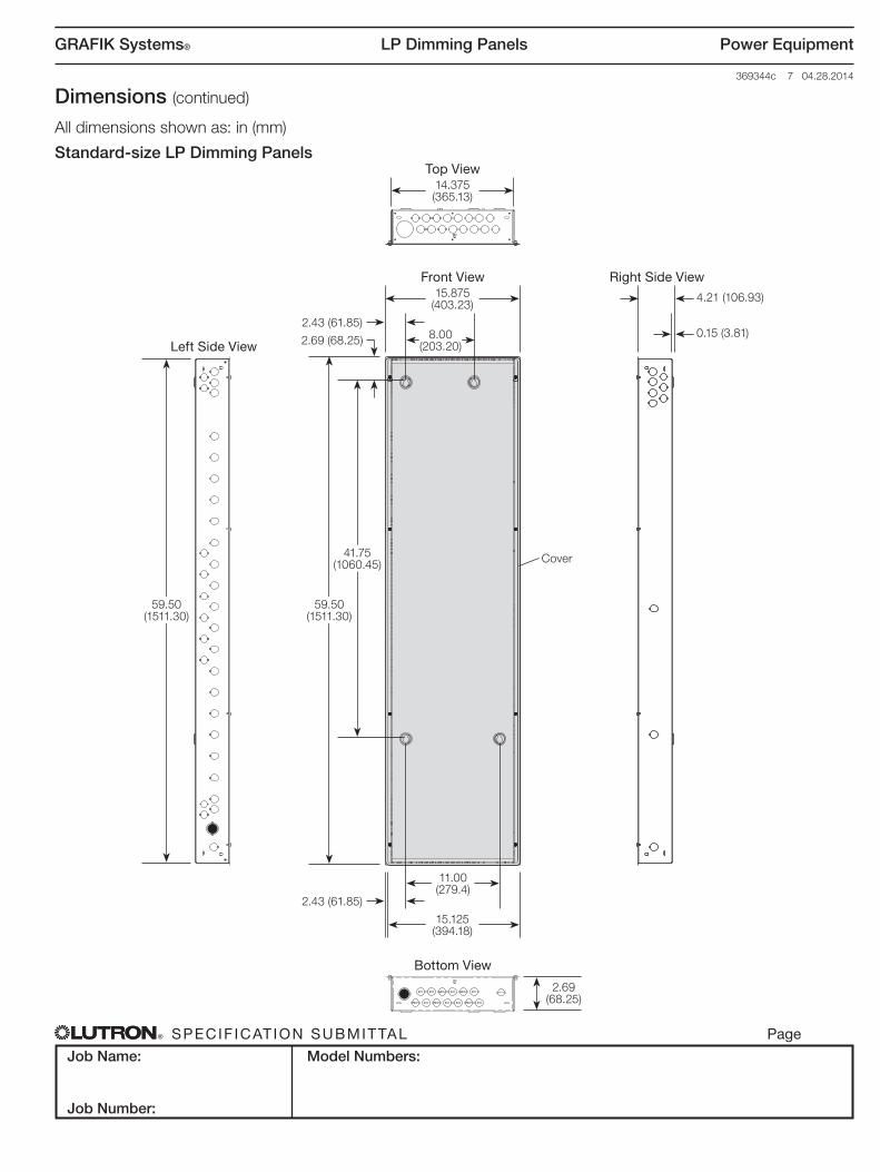
Dimensions (continued)
All dimensions shown as: in (mm)
Standard-size LP Dimming PanelsTop View
14.375(365.13)
Bottom View
2.69 (68.25)
Front View15.875
(403.23)
15.125(394.18)
41.75(1060.45)
59.50(1511.30)
2.43 (61.85)
2.43 (61.85)
2.69 (68.25) 8.00(203.20)
11.00(279.4)
Right Side View
4.21 (106.93)
0.15 (3.81)Left Side View
59.50(1511.30)
Cover

LP Dimming Panels
® SPECIF ICAT ION SUBMITTAL Page
Job Name:
Job Number:
Model Numbers:
GRAFIK Systems® Power Equipment
369344c 8 04.28.2014
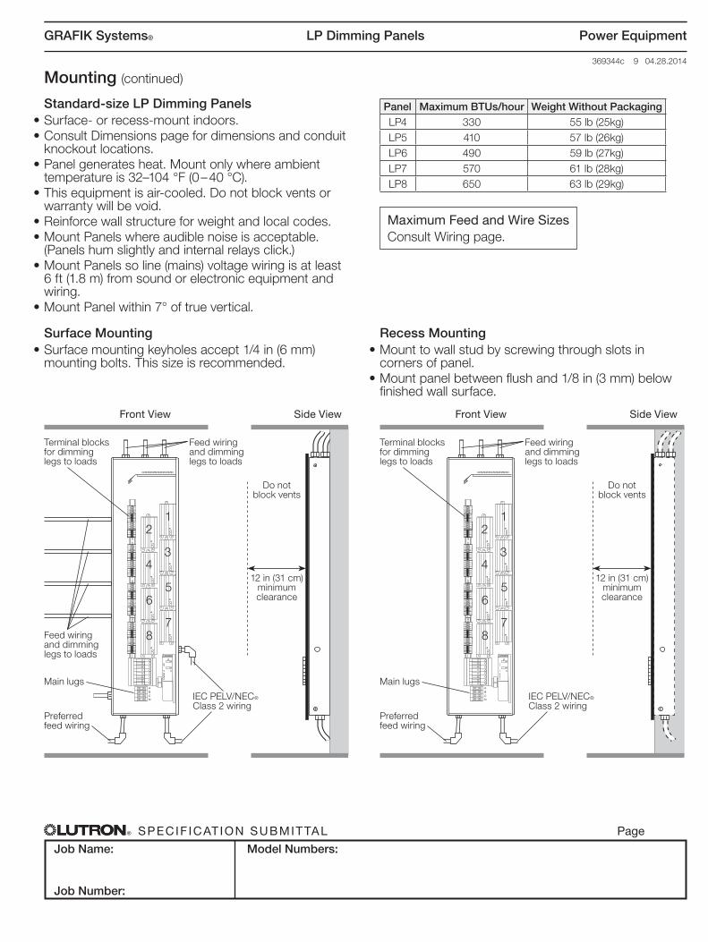
Recess Mounting• Mount to wall stud by screwing through slots in
corners of panel.• Mount panel between flush and 1/8 in (3 mm) below
finished wall surface.
Mounting
Mini LP Dimming Panels• Surface‑ or recess‑mount indoors. • Consult Dimensions page for dimensions and conduit
knockout locations.• Panel generates heat. Mount only where ambient
temperature is 32–104 °F (0 – 40 °C).• This equipment is air‑cooled. Do not block vents or
warranty will be void.• Mount Panels where audible noise is acceptable.
(Panels hum slightly and internal relays click.)• Mount Panels so line (mains) voltage wiring is at least
6 ft (1.8 m) from sound or electronic equipment and wiring.
• Mount Panel within 7° of true vertical.
Surface Mounting• Surface mounting keyholes accept 1/4 in (6 mm)
mounting bolts. This size is recommended.
Maximum Feed and Wire SizesConsult Wiring page.
Panel Maximum BTUs/hour Weight Without PackagingLP1 90 33 lb (15kg)LP2 170 35 lb (16kg)LP3 250 37 lb (17kg)
N
Front View Side View
Feed wiring and dimming legs to loads
Branch circuit breakers
Feed wiring and dimming legs to loads
IEC PELV/NEC® Class 2 wiring
Do not block vents
12 in (31 cm) minimum clearance
Terminal blocks for dimming legs to loads
N
Front View Side View
Branch circuit breakers
Feed wiring and dimming legs to loads
Feed wiring and dimming legs to loads
IEC PELV/NEC® Class 2 wiring
Do not block vents
12 in (31 cm) minimum clearance
Terminal blocks for dimming legs to loads
LP Dimming Panels
® SPECIF ICAT ION SUBMITTAL Page
Job Name:
Job Number:
Model Numbers:
GRAFIK Systems® Power Equipment
369344c 9 04.28.2014
Recess Mounting• Mount to wall stud by screwing through slots in
corners of panel.• Mount panel between flush and 1/8 in (3 mm) below
finished wall surface.
Mounting (continued)
Standard-size LP Dimming Panels• Surface‑ or recess‑mount indoors. • Consult Dimensions page for dimensions and conduit
knockout locations.• Panel generates heat. Mount only where ambient
temperature is 32–104 °F (0 – 40 °C).• This equipment is air‑cooled. Do not block vents or
warranty will be void.• Reinforce wall structure for weight and local codes.• Mount Panels where audible noise is acceptable.
(Panels hum slightly and internal relays click.)• Mount Panels so line (mains) voltage wiring is at least
6 ft (1.8 m) from sound or electronic equipment and wiring.
• Mount Panel within 7° of true vertical.
Surface Mounting• Surface mounting keyholes accept 1/4 in (6 mm)
mounting bolts. This size is recommended.
Maximum Feed and Wire SizesConsult Wiring page.
Panel Maximum BTUs/hour Weight Without PackagingLP4 330 55 lb (25kg)LP5 410 57 lb (26kg)LP6 490 59 lb (27kg)LP7 570 61 lb (28kg)LP8 650 63 lb (29kg)
12
43
56
87
ABCN
Front View Side View
Feed wiring and dimming legs to loads
Feed wiring and dimming legs to loads
Preferred feed wiring
IEC PELV/NEC® Class 2 wiring
Main lugs
Do not block vents
12 in (31 cm) minimum clearance
Terminal blocks for dimming legs to loads
12
43
56
87
ABCN
Front View Side View
Feed wiring and dimming legs to loads
Preferred feed wiring
IEC PELV/NEC® Class 2 wiring
Main lugs
Do not block vents
12 in (31 cm) minimum clearance
Terminal blocks for dimming legs to loads
LP Dimming Panels
® SPECIF ICAT ION SUBMITTAL Page
Job Name:
Job Number:
Model Numbers:
GRAFIK Systems® Power Equipment
369344c 10 04.28.2014
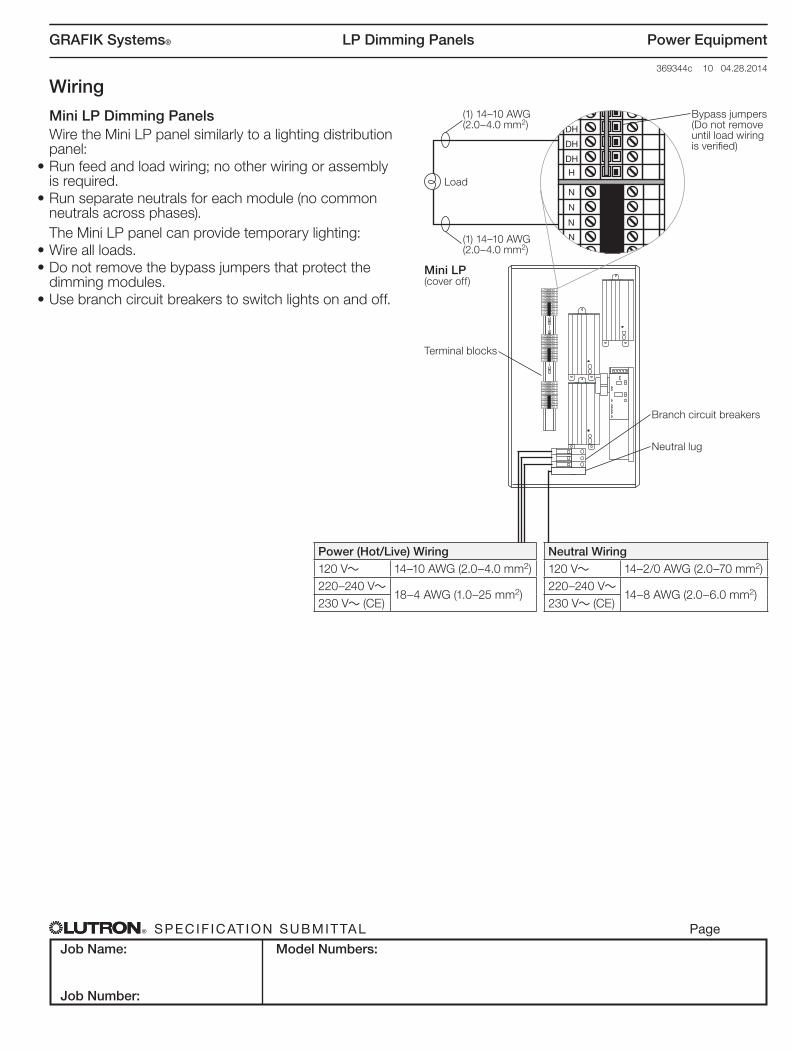
Wiring
Mini LP Dimming PanelsWire the Mini LP panel similarly to a lighting distribution panel:
• Run feed and load wiring; no other wiring or assembly is required.
• Run separate neutrals for each module (no common neutrals across phases).The Mini LP panel can provide temporary lighting:
• Wire all loads.• Do not remove the bypass jumpers that protect the
dimming modules.• Use branch circuit breakers to switch lights on and off.
N
N
DH
H
DH
N
DH
DH
N
N
N
N
DH
H
DH
N
DH
DH
N
N
N
N
DH
H
DH
N
DH
DH
N
N
N
N
DH
H
DH
N
DH
DH
N
N
Bypass jumpers (Do not remove until load wiring is verified)
Mini LP(cover off)
Terminal blocks
Branch circuit breakers
Neutral lug
(1) 14–10 AWG (2.0–4.0 mm2)
(1) 14–10 AWG (2.0–4.0 mm2)
Load
Power (Hot/Live) Wiring120 V~ 14–10 AWG (2.0–4.0 mm2)220–240 V~
18–4 AWG (1.0–25 mm2)230 V~ (CE)
Neutral Wiring120 V~ 14–2/0 AWG (2.0–70 mm2)220–240 V~
14–8 AWG (2.0–6.0 mm2)230 V~ (CE)
LP Dimming Panels
® SPECIF ICAT ION SUBMITTAL Page
Job Name:
Job Number:
Model Numbers:
GRAFIK Systems® Power Equipment
369344c 11 04.28.2014
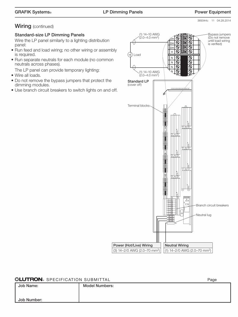
Wiring (continued)
Standard-size LP Dimming PanelsWire the LP panel similarly to a lighting distribution panel:
• Run feed and load wiring; no other wiring or assembly is required.
• Run separate neutrals for each module (no common neutrals across phases).The LP panel can provide temporary lighting:
• Wire all loads.• Do not remove the bypass jumpers that protect the
dimming modules.• Use branch circuit breakers to switch lights on and off.
N
N
DH
H
DH
N
DH
DH
N
N
N
N
N
DH
H
DH
N
DH
DH
N
N
N
N
DH
H
DH
N
DH
DH
N
N
N
N
DH
H
DH
N
DH
DH
N
N
N
N
DH
H
DH
N
DH
DH
N
N
N
N
DH
H
DH
N
DH
DH
N
N
N
N
DH
H
DH
N
DH
DH
N
N
N
N
DH
H
DH
N
DH
DH
N
N
N
N
DH
H
DH
N
DH
DH
N
N
Power (Hot/Live) Wiring(3) 14–2/0 AWG (2.0–70 mm2)
Neutral Wiring(1) 14–2/0 AWG (2.0–70 mm2)
Bypass jumpers (Do not remove until load wiring is verified)
Standard LP(cover off)
Terminal blocks
Branch circuit breakers
Neutral lug
(1) 14–10 AWG (2.0–4.0 mm2)
(1) 14–10 AWG (2.0–4.0 mm2)
Load
LP Dimming Panels
® SPECIF ICAT ION SUBMITTAL Page
Job Name:
Job Number:
Model Numbers:
GRAFIK Systems® Power Equipment
369344c 12 04.28.2014
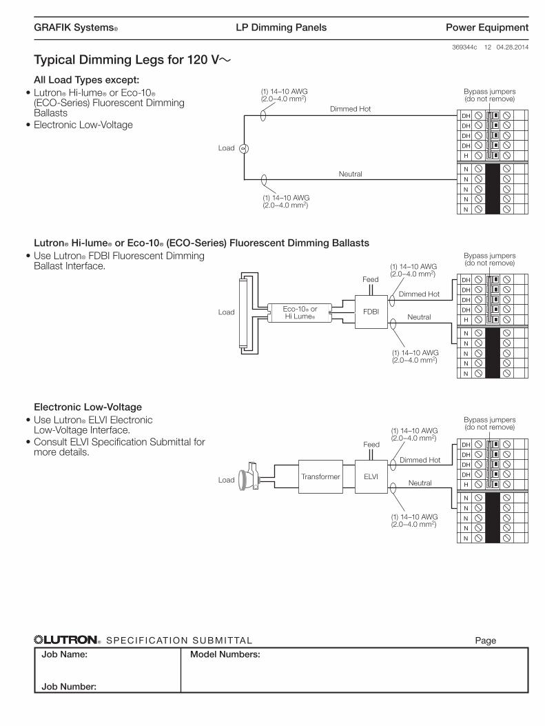
Electronic Low-Voltage• Use Lutron® ELVI Electronic
Low‑Voltage Interface.• Consult ELVI Specification Submittal for
more details.
N
N
DH
H
DH
N
DH
DH
N
N
TransformerLoad
Bypass jumpers (do not remove)
Dimmed Hot
NeutralELVI
Feed
(1) 14–10 AWG (2.0–4.0 mm2)
(1) 14–10 AWG (2.0–4.0 mm2)
Typical Dimming Legs for 120 V~
All Load Types except:• Lutron® Hi‑lume® or Eco‑10®
(ECO‑Series) Fluorescent Dimming Ballasts
• Electronic Low‑Voltage
N
N
DH
H
DH
N
DH
DH
N
N
Load
Bypass jumpers (do not remove)
Dimmed Hot
Neutral
(1) 14–10 AWG (2.0–4.0 mm2)
(1) 14–10 AWG (2.0–4.0 mm2)
Lutron® Hi-lume® or Eco-10® (ECO-Series) Fluorescent Dimming Ballasts• Use Lutron® FDBI Fluorescent Dimming
Ballast Interface.
N
N
DH
H
DH
N
DH
DH
N
N
Eco‑10® or Hi Lume®
Load
Bypass jumpers (do not remove)
Dimmed Hot
NeutralFDBI
Feed
(1) 14–10 AWG (2.0–4.0 mm2)
(1) 14–10 AWG (2.0–4.0 mm2)

LP Dimming Panels
® SPECIF ICAT ION SUBMITTAL Page
Job Name:
Job Number:
Model Numbers:
GRAFIK Systems® Power Equipment
369344c 13 04.28.2014
Typical Dimming Legs for 220 to 240 V~ (non CE)
All Load Types except:• Lutron® Hi‑lume® or Eco‑10®
(ECO‑Series) Fluorescent Dimming Ballasts
• Electronic Low‑Voltage
N
N
DL
L
DL
N
DL
DL
N
N
Load
Bypass jumpers (do not remove)
Dimmed Live
Neutral
(1) 14–10 AWG (2.0–4.0 mm2)
(1) 14–10 AWG (2.0–4.0 mm2)
Electronic Low-Voltage• Use Lutron® ELVI Electronic
Low‑Voltage Interface.• Consult ELVI Specification Submittal for
more details.
N
N
DL
L
DL
N
DL
DL
N
N
TransformerLoad
Bypass jumpers (do not remove)
Dimmed Live
NeutralELVI
Feed
(1) 14–10 AWG (2.0–4.0 mm2)
(1) 14–10 AWG (2.0–4.0 mm2)
Lutron® Hi-lume® or Eco-10® (ECO-Series) Fluorescent Dimming Ballasts• Use Lutron® FDBI Fluorescent Dimming
Ballast Interface.
N
N
DL
L
DL
N
DL
DL
N
N
Eco‑10® or Hi Lume®
Load
Bypass jumpers (do not remove)
Dimmed Live
NeutralFDBI
Feed
(1) 14–10 AWG (2.0–4.0 mm2)
(1) 14–10 AWG (2.0–4.0 mm2)

LP Dimming Panels
® SPECIF ICAT ION SUBMITTAL Page
Job Name:
Job Number:
Model Numbers:
GRAFIK Systems® Power Equipment
369344c 14 04.28.2014
Typical Dimming Legs for 230 V~ (CE)
All Load Types except:• Lutron® Hi‑lume® or Eco‑10®
(ECO‑Series) Fluorescent Dimming Ballasts
• Electronic Low‑Voltage
N
N
DL
L
DL
N
DL
DL
N
N
Load
Bypass jumpers (do not remove)
Dimmed Live
Neutral
(1) 14–10 AWG (2.0–4.0 mm2)
(1) 14–10 AWG (2.0–4.0 mm2)
Electronic Low-Voltage• Use Lutron® ELVI Electronic
Low‑Voltage Interface.
N
N
DL
L
DL
N
DL
DL
N
N
TransformerLoad
Bypass jumpers (do not remove)
Dimmed Live
NeutralELVI
Feed
(1) 14–10 AWG (2.0–4.0 mm2)
(1) 14–10 AWG (2.0–4.0 mm2)
LP Dimming Panels
® SPECIF ICAT ION SUBMITTAL Page
Job Name:
Job Number:
Model Numbers:
GRAFIK Systems® Power Equipment
369344c 15 04.28.2014369‑344A‑15 11.03.10
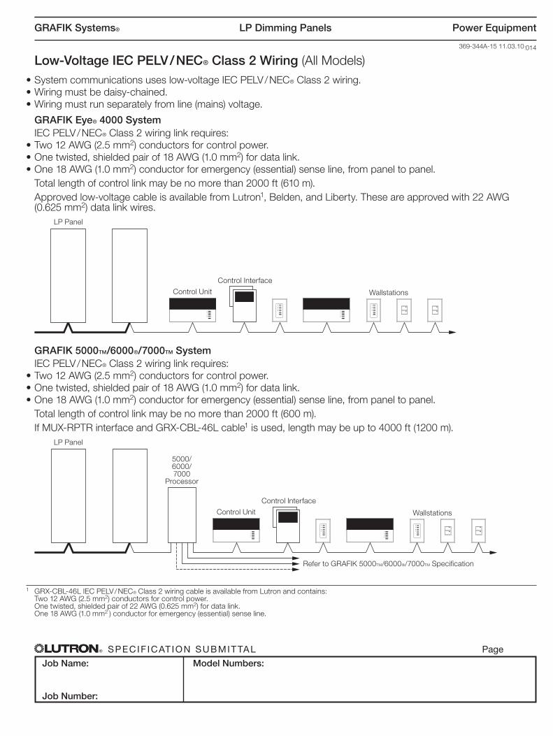
Low-Voltage IEC PELV / NEC® Class 2 Wiring (All Models)• System communications uses low‑voltage IEC PELV / NEC® Class 2 wiring. • Wiring must be daisy‑chained.• Wiring must run separately from line (mains) voltage.
GRAFIK Eye® 4000 SystemIEC PELV / NEC® Class 2 wiring link requires:
• Two 12 AWG (2.5 mm2) conductors for control power.• One twisted, shielded pair of 18 AWG (1.0 mm2) for data link.• One 18 AWG (1.0 mm2) conductor for emergency (essential) sense line, from panel to panel.
Total length of control link may be no more than 2000 ft (610 m).Approved low‑voltage cable is available from Lutron1, Belden, and Liberty. These are approved with 22 AWG (0.625 mm2) data link wires.
GRAFIK 5000TM/6000®/7000TM SystemIEC PELV / NEC® Class 2 wiring link requires:
• Two 12 AWG (2.5 mm2) conductors for control power.• One twisted, shielded pair of 18 AWG (1.0 mm2) for data link.• One 18 AWG (1.0 mm2) conductor for emergency (essential) sense line, from panel to panel.
Total length of control link may be no more than 2000 ft (600 m).If MUX‑RPTR interface and GRX‑CBL‑46L cable1 is used, length may be up to 4000 ft (1200 m).
1 GRX‑CBL‑46L IEC PELV / NEC® Class 2 wiring cable is available from Lutron and contains: Two 12 AWG (2.5 mm2) conductors for control power. One twisted, shielded pair of 22 AWG (0.625 mm2) for data link. One 18 AWG (1.0 mm2 ) conductor for emergency (essential) sense line.
LP Panel
Control Unit
Control Interface
Wallstations
LP Panel
5000/ 6000/ 7000
Processor
Refer to GRAFIK 5000TM/6000®/7000TM Specification
Control Unit
Control Interface
Wallstations
LP Dimming Panels
® SPECIF ICAT ION SUBMITTAL Page
Job Name:
Job Number:
Model Numbers:
GRAFIK Systems® Power Equipment
369344c 16 04.28.2014
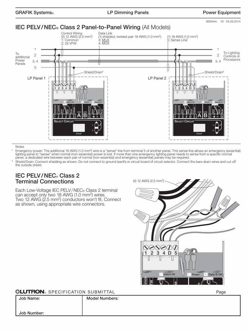
Notes* Emergency power: The additional 18 AWG (1.0 mm2) wire is a “sense” line from terminal 5 of another panel. This sense line allows an emergency (essential)
lighting panel to “sense” when normal (non‑essential) power is lost. If more than one emergency lighting panel needs to sense from a specific normal panel, a dedicated wire between each pair of normal (non‑essential) and emergency (essential) panels may be required.
† Shield/Drain: Connect shielding as shown. Do not connect to ground (earth) or circuit board of circuit selector. Connect the bare drain wires and cut off the outside shield.
IEC PELV / NEC® Class 2 Terminal ConnectionsEach Low‑Voltage IEC PELV / NEC® Class 2 terminal can accept only two 18 AWG (1.0 mm2) wires. Two 12 AWG (2.5 mm2) conductors won’t fit. Connect as shown, using appropriate wire connectors.
SELECT CIRCUIT
2
1
Circuit
Data A OK Power
1 2 3 4 5D
Co
mm
on
24V
FW
MU
X
MU
X
Dra
inS
ense
1 2 3 4 D 5
Data B OK
B Co
mm
Dra
in
MU
X
MU
X
C D
Link
ALink
IEC PELV / NEC® Class 2 Panel-to-Panel Wiring (All Models)
SELECT CIRCUIT
Data A OK Power Data B OK
1 2 3 4 D 5
1 2 3 4 D 5 C D
Co
mm
on
Co
mm
on
+24
VF
W
Sen
se
MU
X
MU
X
Dra
in
Dra
in
MU
X
MU
X
Circuit
1
2
Link
ALink
BSELECT CIRCUIT
Data A OK Power Data B OK
1 2 3 4 D 5
1 2 3 4 D 5 C D
Co
mm
on
Co
mm
on
+24
VF
W
Sen
se
MU
X
MU
X
Dra
in
Dra
in
MU
X
MU
X
Circuit
1
2
Link
ALink
B
Control Wiring(2) 12 AWG (2.5 mm2)1: Common2: 24 VFW
To additional Power Panels
LP Panel 1 LP Panel 2
To Lighting Controls or Processors
Shield/Drain† Shield/Drain†
(1) 18 AWG (1.0 mm2)5: Sense Line1
Data Link(1) shielded, twisted pair 18 AWG (1.0 mm2)3: MUX4: MUX
1
2
3, 4
5
1
2
3, 4
(4) 12 AWG (2.5 mm2)
LP Dimming Panels
® SPECIF ICAT ION SUBMITTAL Page
Job Name:
Job Number:
Model Numbers:
GRAFIK Systems® Power Equipment
369344c 17 04.28.2014
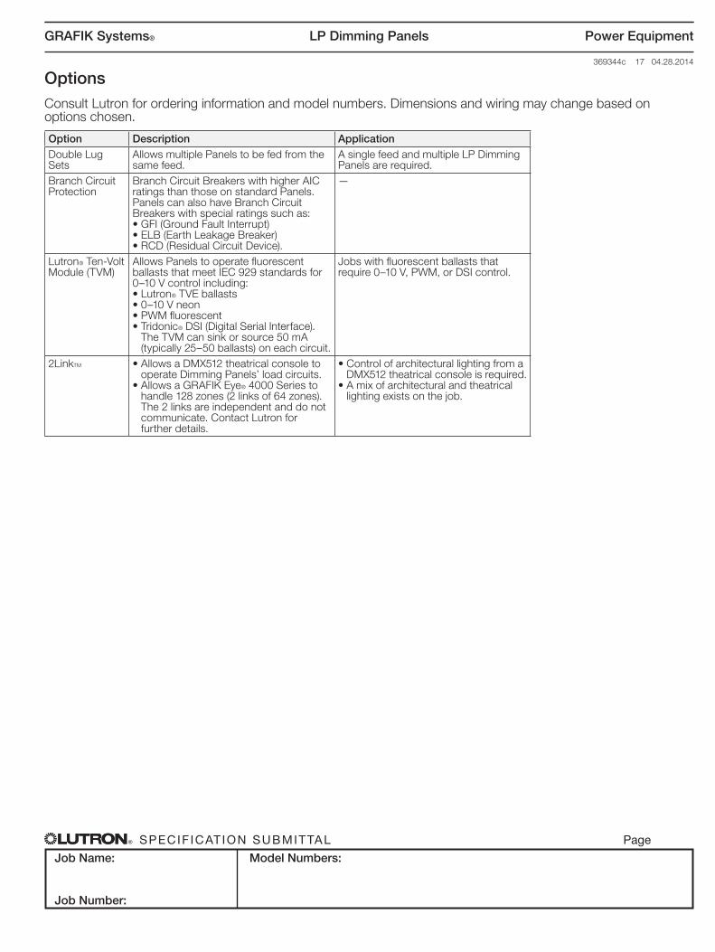
OptionsConsult Lutron for ordering information and model numbers. Dimensions and wiring may change based on options chosen.
Option Description ApplicationDouble Lug Sets
Allows multiple Panels to be fed from the same feed.
A single feed and multiple LP Dimming Panels are required.
Branch Circuit Protection
Branch Circuit Breakers with higher AIC ratings than those on standard Panels.Panels can also have Branch Circuit Breakers with special ratings such as:• GFI (Ground Fault Interrupt)• ELB (Earth Leakage Breaker)• RCD (Residual Circuit Device).
—
Lutron® Ten‑Volt Module (TVM)
Allows Panels to operate fluorescent ballasts that meet IEC 929 standards for 0–10 V control including:• Lutron® TVE ballasts• 0–10 V neon• PWM fluorescent• Tridonic® DSI (Digital Serial Interface).
The TVM can sink or source 50 mA (typically 25–50 ballasts) on each circuit.
Jobs with fluorescent ballasts that require 0–10 V, PWM, or DSI control.
2LinkTM • Allows a DMX512 theatrical console to operate Dimming Panels’ load circuits.
• Allows a GRAFIK Eye® 4000 Series to handle 128 zones (2 links of 64 zones). The 2 links are independent and do not communicate. Contact Lutron for further details.
• Control of architectural lighting from a DMX512 theatrical console is required.
• A mix of architectural and theatrical lighting exists on the job.