Embed Size (px)
Citation preview
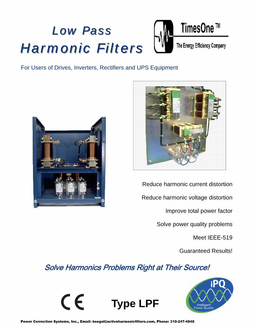
Low PassLow Pass
Harmonic FiltersHarmonic FiltersFor Users of Drives, Inverters, Rectifiers and UPS Equipment
Reduce harmonic current distortion
Reduce harmonic voltage distortion
Improve total power factor
Solve power quality problems
Meet IEEE-519
Guaranteed Results!
Solve Harmonics Problems Right at Their Source!
Type LPF

2
About Harmonics and IEEE—519
Sources of Harmonics i i
il
l
Problems Caused by Harmonics Effects of the di elevated true rms (Trms) current and
All together, increased burden on
as reduced equipment life. i
i i li i Al
energy. In many cases, may
IEEE - STD - 519 imi i i ic
neighboring facilities, IEEE-std-519 In 1992
l
i The following chart icurrent (ISC) to the maximum demand load current (IL i
Connection (PCC).
Optional Locations for Mitigation Equipment
lyi i ilother l li
Solve Harmonics Right at Their Source TIMES ONE ™
i i l i l itii
well as upstream. i
the typical limi ill l
Comprehensive Facility Analysis Available TIMES ONE ™ i i
i i
(6-pulse rectifier)
ISC / IL h < 11 11<h<17 17<h<23 23<h<35 35 < h TDD-I
< 20 5%
8%
12%
15%
20%
In recent years, t has become apparent that power electron cs equipment is contributing to power system voltage distortion. These energy saving and power reliability products such as adjustable speed motor drives (ASD), and uninterrupt ble power supplies (UPS) do not draw current in the norma continuous and sinusoidal manner, but instead take discontinuous gulps of current. ASDs and UPSs often convert three phase AC input voltage to DC through the use of a ful wave bridge rectifier consisting of six diodes (6-pulse rectifier). The pulsed current waveforms associated with six pulse rectifiers, contain not only a 60hz component but also multiple higher frequencies called harmonics.
storted current included high peak current, reduced total power factor. this means lower system efficiency, electrical equipment such as transformers, possible equipment malfunction or interference, as well
When one or more loads in a facil ty cause harmonic current distortion, the system voltage and current will also become distorted, and have an impact on other loads connected to the same power source. Facility managers have noticed that harmonics can have an adverse effect on equipment life. Elevated Trms current increases the I squared R losses which cause increased equipment heating , reducing the life of motors and transformers. When the continuous operating temperature of this equ pment is increased by only 10 degrees Celsius, t’s fe expectancy decreases as much as f fty percent. though you are employing energy saving equipment, you will not achieve the maximum energy savings due to the consumption of wasteful harmonic
these same pieces of equipment intended to increase the reliability of the power supplied to their loads, actually create power quality problems for other pieces of equipment supplied from the same voltage source.
To min ze the mpact of facil ty harmondistortion on the utility power system and on
was developed and published in 1982. it was updated and re-published. This standard provides recommended limits for totaharmonic voltage and current distortion as well as for indiv dual harmonic currents.
indicates the limits for current distortion imposed by this standard based upon the ratio of available short c rcuit ). This analysis is typically performed at the point where a facil ty power system is
connected to the electric utility power system. This point is referred to as the Point of Common Coupling or Point of Common
The objective of the standard can be met by applying harmonic mitigation equipment either at the PCC or at appropriate points downstream from the PCC. App ng harmon c f ters near the PCC improves the power quality for all points upstream. The utility and
facilities connected to the same utility feed receive the benefit of improved power qua ity, but your faci ty does not.
offers a full range of solutions for harmonic distortion. Our Low Pass Harmonic Filter is the ideal solution for minimizing harmonics r ght at the indiv dual loads. This removes harmonics from al po nts up stream of these oads. When harmonic m gation equipment is applied close to the indiv dual harmonic producing loads, the power quality can be improved throughout the facility as
For the purpose of improving the internal power quality, IEEE-std-519, 10.1 states that “within an industrial plant, the PCC is the point between the non-linear load and other loads.” When the PCC is considered at an indiv dual piece of equipment,
ts for harmonic current distort on are 8%, 12% or 15%. When you apply our Low Pass Harmonic Filter to an individual load or group of loads, the harmonic current distortion will typica y be reduced to 5% or ess.
can also perform a comprehensive facility analys s for you. Typically we’ll work directly from your s ngle line diagram with consideration for any existing problems and your des red power quality objectives. We’ll recommend the best technical and economical solution that will meet your objectives. Your potential benefits nclude: increased equipment life, reduced power losses, improved equipment operation, reduced equipment down time, and ultimately — increased productivity and operating profits.
Input current waveform
4.0 2.0 1.5 0.6 0.3
20 < 50 7.0 3.5 2.5 1.0 0.5
50 < 100 10.0 4.5 4.0 1.5 0.7
100 < 1000 12.0 5.5 5.0 2.0 1.0
1000 up 15.0 7.0 6.0 2.5 1.4

3
Solve Harmonics Problems at Their Source!
Get these Benefits ... Reduce transformer and motor temperature
= Extend equipment life
Reduce true rms and peak current = Eliminate disruptions caused by nuisance
fuse and circuit breaker operation
Reduce KVA demand = More power from existing power sources
Reduce facility power loss = Energy cost savings
Eliminate equipment interference = Improve equipment operation
Improve total power factor = Reduce KVA consumption
Improve productivity and profits!
TIMES ONE ™ LPF Harmonic Filters
• Harmonic current distortion
• Harmonic voltage distortion
• Transformer over-loading
• Transformer over-heating
• Motor over-heating
•
• Nuisance circuit breaker tripping
•
•
• Capacitor failure
Problems Solved by Type
Nuisance fuse blowing
Low total power factor
Equipment interference
LPF Maximizes the Power Available from Transformers and Generators Harmonics increase the KVA burden on transformers and Power Source Capacity Available generators. The higher the when all loads are Non-Linear harmonic distortion, the higher 100% the true rms current and KVA demand. 80%
TIMES ONE ™ Low Pass
Cap
acity
60% Harmonic Filters will help you to get the most out of existing transformers and generators.
40%
20%By reducing harmonic current distortion to extremely low levels, 0% current and KVA demand of existing 1.50% 3.00% 5.00% 6.25% loads are both reduced, freeing
Transformer Impedance up capacity in your existing transformers or generators. No Filter With Filter Since harmonic distortion reduces the total power factor, it causes energy efficiency to suffer and reduces the available capacity of power sources such as transformers, generators and conductors. As the percentage of nonlinear load on a transformer increases, its available KVA capacity decreases.
Note: Type LPF harmonic filters meet the requirements of UL-508, IEEE-519, IEEE-1531 and the CE Low Voltage Directive. Design engineering and production are performed in a facility that is currently registered to ISO-9001:2000 by UL.

4
Low Pass Harmonic Filter Performance
TIMES ONE ™ three
Input Stage
Shunt Stage
Low Pass Harmonic Filters (LPF) offer stages of filtering that nearly eliminate the harmonics
normally produced by three phase equipment using six pulse rectifiers. Our LPF is intended for adjustable speed drives, uninterruptible power supplies, and other rectifier controls, with any source impedance.
The purpose of this stage is to isolate the LPF from other harmonics sources connected to the same power source, prevent power system resonance and to provide series impedance that will reduce the spectrum of harmonics produced by the load. This stage also protects the load against voltage transients.
Output Stage The output stage contains a precise amount of impedance that supplements the input stage impedance to minimize the amount of harmonics produced by the load. It also reduces the harmonic burden placed on the shunt stage, and prevents resonance between the shunt stage and the load.
The shunt stage absorbs residual harmonics remaining after both the input and output stages have played their roles in reducing load harmonics. Our basic three stage filter design achieves anti-resonance operation of our shunt stage.
Three Stages of Harmonic Filtering The input current waveform is a primary indicator of the relative harmonic current distortion. The nearer to a sine wave, the less distortion. The worst case scenario is when the power source impedance is low (ie: 1% or less). This results in very high distortion, increased true rms current and very high peak current.
The waveforms below illustrate the typical waveform to be expected for a VFD connected directly to the line with a source impedance of 1%, with a 5% impedance reactor, and with the TIMES ONE ™Low Pass Harmonic Filter. Notice that the LPF improves the current waveform to nearly a sine wave.
Actual Waveform Measurements
)
with
Motor drive (VFD) with Low Pass Filter (LPFActual THD-I = 4.72% (Nearly a sine wave)
Motor drive, no filter, with line reactor 5% effective impedance Actual THD-I = 35.2%
Motor drive, no filter, and 0.5% effective
source impedance Actual THD-I = 99.9%
TIMES ONE ™ Low Pass HarmonicComparison of residual harmonics for a drive with and without
0% 5 7 11 13 17
Wi
Wi
Harmonic Spectrum
spectrum for a 6-pulse
of 1% relative to the drive KVA rating.
Type LPF harmonic filters
20%
40%
60%
80%
100%
Fund Harmonic
THD
-I
thout LPF
th LPF
This is an actual harmonic
drive (VFD), operating at full load, and having an effective source impedance
achieve less than 5% Total harmonic current distortion.

5 Superior Performance by Design
TIMES ONE ™ Type LPF Harmonic Filters perform better because our LPF is designed for real life applications with virtually any source impedance. Furthermore, our reactors and capacitors have unique characteristics that enable our filter to achieve maximum reduction of harmonics.
Proprietary Reactor Design Reactors have a major influence over the performance of harmonic filters. Optimum performance of any harmonic filter demands accurate and balanced phase to phase inductance in all three reactor coils. Additionally, both power loss and life expectancy are affected by the reactor’s ability to handle harmonics with minimal power loss.
Reactors used in TIMES ONE ™ Type LPF filters have inductance balanced within1% to 3% between all three phases, (competitive products can be 5 to 15%). Our reactors are constructed with exclusive PolyGapTM core construction which strategically distributes the air gap into numerous tiny air gaps placed at precise locations within the core. PolyGapTM core construction achieves balanced phase inductance with negligible gap (fringing) losses and virtually eliminates stray magnetic flux. Reactors used as part of the shunt stage include an over temperature switch that may be used to send an alarm in the event the filter has been inadvertently overloaded. Reactors used in TIMES ONE ™ Type LPF filters are tested with actual harmonics currents and are UL component recognized.
Exclusive Capacitor Design Capacitors are the heart of any harmonic filter. Traditionally, they have been the first items to fail in a filter because their life is adversely affected by temperature, terminal voltage, and the true rms current that flows due to both fundamental and harmonic currents. TIMES ONE ™ capacitors are specially designed and constructed for harmonic filter applications. They are designed with a physical geometry optimizes dissipation of heat in order to achieve the lowest possible internal temperature. Although our capacitors are designed for operation at temperatures up to 85 degrees Celcius, the normal operating temperature of our Type LPF filters is much lower resulting in life expectancy as high as 1,000,000 hours of operation (at 40C). Capacitors used in TIMES ONE ™ Type LPF filters are UL component recognized.
UPS,
Three Stage FilterTIMES ONE ™
Our filters are engi
tering
TIMES ONE ™
Type LPF filters provide three stages of filtering to perform wide band attenuation of normal harmonic frequencies associated with balanced three phase loads that use 6-pulse rectifiers (such as adjustable speed drives, frequency converters, etc.). For properly selected and applied LPF filters, the total harmonic current distortion at the filter input terminals will normally be 5% THD-I or less and will always be 8% THD-I or less. The distortion at the utility metering point can be well under 5% THD-I when other linear loads are operating. Actual distortion levels may increase slightly for unbalanced line voltage and when voltage distortion is caused by other loads.
combines the highest grade reactors and capacitors into a three stage filter that performs wide band filtering of virtually all harmonic frequencies produced by a typical 6-pulse rectifier. neered to deliver the highest performance in the most rigorous of applications. Our three stage approach to fil
enables our filter to be used on virtually any drive or UPS using 6-pulse rectification, whether supplied from a transformer, generator or distributed generation power source (inverter). Our LPF filters are suitable for :
Diode converter with or without internal inductance SCR converter with or without internal inductance Constant torque applications Variable torque applications Non-Linear loads supplied form inverter power sources
Other filters may look similar, but lack the exclusive design characteristics, construction techniques and overall performance of our reactors and capacitors. While others may use less series inductance, in the interest of lowering their costs, puts the ideal inductance into each filter in order to achieve superior performance over the entire load range and enabling our Type LPF filter to be used with virtually any power source.

6
Performance Specifications
The key benefit of the Low Pass Harmonic Filter (LPF) is low residual harmonic current distortion with good voltage regulation. Each is fully described in the following graphs. The LPF is suitable for use with any source impedance (no need to add more reactors to meet a minimum impedance level). Residual distortion and output voltage will both vary with effective source impedance (%Zeff) as shown.
Current Distortion % Harmonic Current Distortion vs. %Zeff The chart to the left
illustrates the typical current distortion
0
1
2
3
4
5
6 loading conditions.
These distortion levels can be achieved wi l conditions and have
life applications
voltage distortion
Actual distortion
% T
HD
-I
0.25% Zeff 2% Zeff 5% Zeff
expected at various
th idea
been attained in real
where supply voltages were balanced and power system
was minimal.
may be higher if voltage is unbalanced or distorted, and for applications other than 6-pulse
% % % % % % 0%% % %5 .5 30 .5 .55 0 75 .5
12 7 62 7 102 53 8% LOAD voltage source
converters.
100%75%50%25%0%
/
Vout vs Vin vs. %Zeff
0.900 0.920 0.940 0.960 0.980 1.000 1.020 1.040 1.060
87.5% 62.5% 37.5% 12.5% % LOAD
Vout
Vin
0.25% Zeff 2% Zeff 5% Zeff
Voltage Regulation TIMES ONE ™ Low Pass Harmonic Filters perform with very good regulation of output voltage. The highest output voltage will be experienced at no load conditions, and the lowest output voltage will be at full load.
The typical range of voltage will be within +/- 5% of system voltage. As illustrated in the chart to the right, actual voltage can vary slightly based upon the effective source impedance.
System Voltage:
)
General Specifications: (For use at input to 6-pulse rectifier type VFD or UPS)
Rated Voltage +/- 10% System Frequency: Rated Frequency +/- 1 Hz Maximum Current: Rated Current (continuousTemporary Overload: 150% x Rated Current (one minute) Minimum Impedance: Suitable for use with any source impedance Harmonic Distortion: 5% Typical Total Harmonic Current Distortion
8% THD-I Guaranteed, 5% TDD Guaranteed.

7 Selection is easy! Type LPF filters are suitable for 6-pulse rectified, non-linear loads only. LPF filters are not intended for use with linear loads. Select the appropriate LPF based on your application type.
Variable Torque: (Fans and pumps operated by variable frequency drives) Determine the total load (horsepower, KW or current) rating. Select the appropriate filter based on either HP, KW or full load current.
Constant Torque: (Non-fan and pump applications)Determine the maximum current (ampere) requirement. Select the appropriate filter based on the maximum required current in amperes. Example: a 100HP, 124FLA motor drive, to be operated temporarily at 130% over current requires a filter rated for at least 161 amps (proper selection is LPF 125 - 480N1).
Other electrical ratings: Consult factory for other frequency, voltage or current ratings.
SCR Phase Control applications: Consult factory.
Medium Voltage Filters: Consult factory.
Other special requirements: Contact factory.
open Type LPF products are available
l
Floor
Wall
Choose from a wide variety of industrial enclosure styles including Nema 1, Nema 3R, Nema 12, panel (chassis) or loose components for your own panel assembly. with enclosures that are suitable for either wall mounting or floor standing
Open Pane
Nema 1
Standing
Nema 12
Mount Nema 1 or 12 Industrial Enclosure
Optional Enclosure Styles

8 440 - 480 Volt, 60Hz Selection Table
HP KW Max Load Amps
Catalog Number
Watts Loss
Efficiency %
2 1.5 4 LPF 2 - 480 N1 80 94.6
4 3 6.6 LPF 4 - 480 N1 131 95.6
5 3.7 8.0 LPF 5 - 480 N1 131 96.5
7.5 5.5 12.8 LPF 7.5 - 480 N1 192 96.5
10 7.5 19 LPF 10 - 480 N1 252 96.6
15 11 24 LPF 15 - 480 N1 283 97.4
20 15 31 LPF 20 - 480 N1 314 97.9
25 18.5 39 LPF 25 - 480 N1 375 97.9
30 22 48 LPF 30 - 480 N1 416 98.1
40 30 61 LPF 40 - 480 N1 458 98.4
50 37 72 LPF 50 - 480 N1 500 98.6
60 45 84 LPF 60 - 480 N1 562 98.7
75 55 102 LPF 75 - 480 N1 645 98.8
100 75 138 LPF 100 - 480 N1 810 98.9
125 93 175 LPF 125 - 480 N1 1005 98.9
150 112 210 LPF 150 - 480 N1 1190 98.9
200 150 286 LPF 200 - 480 N1 1410 99.0
250 186 334 LPF 250 - 480 N1 1520 99.1
300 225 406 LPF 300 - 480 N1 1830 99.1
350 261 478 LPF 350 - 480 N1 2050 99.1
400 300 550 LPF 400 - 480 N1 2380 99.2
450 335 619 LPF 450 - 480 N1 2650 99.2
500 373 667 LPF 500 - 480 N1 2900 99.2
•
•
•
•
• Others as required.
Standard Modifications Available: Capacitor cut-out contactor Filter bypass system VFD & filter combined bypass system Hybrid filters with PFC

9
Low Pass Harmonic Filter with
Current sensing relay and
i
output circui l
Capacitor cut-out contactor
Open Panel type with current sensing relay and capacitor cut-out contactor. This version can improve power factor at light load and at no-load conditions. The capacitor cut-out modification utilizes an adjustable current sensing relay to mon tor output circuit current and to disconnect the capacitor when
t current falls be ow a pre-set level.
TIMES ONE ™ Low Pass Harmonic Filters are supplied with field wiring terminal blocks for easy connection of customer input and output wiring.
HP KW Max
Number Watts
%
1 .75 5.2 61 91.8 1.5 1.1 7.8 81 92.7 2 1.5 10.3 111 92.6 3 2.2 12.5 111 94.9 4 3 17.7 142 95.2 6 4.5 26 192 95.7
7.5 5.5 34 263 95.2 15 11 52 373 96.6 20 15 69 367 97.5 25 18.5 86 459 97.5 30 22 103 500 97.7 35 26 129 577 97.7 45 33 164 669 97.9 55 41 190 691 98.3 70 52 242 824 98.4 90 67 311 97.0 115 85 388 98.6 135 100 448 98.7 190 141 603 98.8
HP KW Max
Number Watts
%
1 .75 4.5 61 91.8 1.5 1.1 6.9 81 92.6 2 1.5 9.1 111 92.6 3 2.2 10.8 111 94.9 5 3.7 15.2 141 96.1
7.5 5.5 22.7 192 96.5 10 7.5 30 262 96.5 15 11 45 372 96.6 20 15 60 384 97.4 25 18.5 75 455 97.5 30 22 91 496 97.7 40 30 113 578 98.0 50 37 144 670 98.1 60 45 166 692 98.4 75 55 212 825 98.5 100 75 272 98.6 120 90 341 98.7 150 110 394 98.8 200 150 530 98.8
Load Amps
Catalog Loss
Efficiency
LPF 1 - 208 N1 LPF 1.5 -208 N1 LPF 2 -208 N1 LPF 3 -208 N1 LPF 4 -208 N1 LPF 6 -208 N1
LPF 7.5 - 080 N1 LPF 15 -208 N1 LPF 20 - 208 N1 LPF 25 - 208 N1 LPF 30 - 208N1 LPF 35 - 208N1 LPF 45 - 208 N1 LPF 55 - 208 N1 LPF 70 - 208 N1 LPF 90 - 208 N1 1018
LPF 115 - 208 N1 1153 LPF 135 - 208 N1 1287 LPF 190 - 208 N1 1668
208 Volt, 60Hz Selection Table
Load Amps
Catalog Loss
Efficiency
LPF 1 - 240 N1 LPF 1.5 -240 N1 LPF 2 -240 N1 LPF 3 -240 N1 LPF 5 -240 N1
LPF 7.5 -240 N1 LPF 10 - 240 N1 LPF 15 –240 N1 LPF 20 - 240 N1 LPF 25 - 240 N1 LPF 30 - 240N1 LPF 40 - 240N1 LPF 50 - 240 N1 LPF 60 - 240 N1 LPF 75 - 240 N1
LPF 100 - 240 N1 1010 LPF 120 - 240 N1 1154 LPF 150 - 240 N1 1290 LPF 200 - 240 N1 1670
220 - 240 Volt, 60Hz Selection Table
Customized filters available: TIMES ONE ™ can customize any harmonic filter to meet your exact needs. Typical options include power quality meter, filter bypass, capacitor cutout contactor, hybrid filter/power factor system.

10 380 - 415 Volt, 50Hz Selection Table
HP KW Max Load Amps
Catalog Number
Watts Loss
Efficiency %
2 1.5 4 LPF 2 - 400 N1 81 94.6
4 2.2 6.6 LPF 4 - 400 N1 121 94.5
5 3.7 11 LPF 5 - 400 N1 191 94.8
7.5 5.5 14 LPF 7.5 - 400 N1 212 96.1
10 7.5 19 LPF 10 - 400 N1 242 96.7
15 11 24 LPF 15 - 400 N1 303 97.2
20 15 31 LPF 20 - 400 N1 373 97.5
25 18.5 48 LPF 25 - 400 N1 414 97.7
30 22 61 LPF 30 - 400 N1 435 98.0
40 30 72 LPF 40 - 400 N1 526 98.2
50 37 84 LPF 50 - 400 N1 578 98.4
60 45 102 LPF 60 - 400 N1 682 98.4
75 55 138 LPF 75 - 400 N1 815 98.5
100 75 175 LPF 100 - 400 N1 1010 98.6
125 93 210 LPF 125 - 400 N1 1215 98.6
167 125 286 LPF 167 - 400 N1 1404 98.8
200 150 334 LPF 200 - 400 N1 1570 98.9
250 185 406 LPF 250 - 400 N1 1890 98.9
300 225 478 LPF 300 - 400 N1 2060 99.0
350 260 550 LPF 350 - 400 N1 2450 99.0
itor output circui
•
•
•
•
• Others as required.
Open Panel type with current sensing relay and capacitor cut-out contactor. This version can improve power factor at light load and at no-load conditions. The capacitor cut-out modification utilizes an adjustable current sensing relay to mon
t current and to disconnect the capacitor when output circuit current falls below a pre-set level.
Standard Modifications Available: Capacitor cut-out contactor Filter bypass system VFD & filter combined bypass system
Hybrid filters with PFC

11
equipment malfunction or failure.
TIMES ONE ™ your facility.
tion to meet your power quality objectives.
technologies. TIMES ONE ™
loads. Some loads may need nothing at all, while for other loads we will recommend
quality at the lowest cost.
There is no single solution that does it all. That’s why TIMES ONE ™ offers the most
power quality.
Comprehensive Solutions for Facility Power Quality Improvement Facility power quality can degrade as non-linear loads (UPS, VFD, rectifiers, inverters, PCs, etc) are connected to a facility power system. Harmonics from each individual load have a cumulative effect on power system distortion and may cause unwanted interactions between various pieces of power electronic equipment as well as
can help you to restore and maintain high quality electrical power within Based on our analysis of your single line diagrams, power quality data,
and your power quality disturbance history, we’ll recommend the most economical solu
Due to the variety of load types and ratings within a typical facility, the comprehensive approach to power quality generally requires the use of multiple harmonic mitigation
will examine the effects of individual non-linear loads on your overall power system quality and select the ideal technology for each of the major
the best economical solution that will enable us to achieve the desired facility power
complete range of harmonic mitigation technology, as demonstrated by the chart above. We can apply the right solution at the right location to meet your budget for facility

12
TIMES ONE ™ - for the right solution to Power Quality! Harmonic Filters
Power Factor Improvement VAR Compensation
Low, Medium & High Voltage equipment available!