Embed Size (px)
Citation preview
LPRF Board APIReference Manual
JN-RM-2003
Revision 2.4
31 October 2016
LPRF Board APIReference Manual
2 © NXP Laboratories UK 2016 JN-RM-2003 v2.4
LPRF Board APIReference Manual
Contents
Preface 7Organisation 7
Conventions 7
Acronyms and Abbreviations 8
Related Documents 8
Support Resources 8
Trademarks 8
1. Introduction 91.1 Software Installation 9
1.2 Board Types 9
1.3 API Organisation and Location 10
2. Light Sensor Functions 11vALSreset 12
vALSstartReadChannel 13
u16ALSreadChannelResult 14
vALSpowerDown 15
3. Temperature/Humidity Sensor Functions 17vHTSreset 18
vHTSstartReadTemp 19
u16HTSreadTempResult 20
vHTSstartReadHumidity 21
u16HTSreadHumidityResult 22
4. LED Functions 234.1 General LED Functions 23
vLedInitRfd 24
vLedInitFfd 25
vLedControl 26
4.2 RGB and White LED Functions (DR1175 only) 27bRGB_LED_Enable 28
bRGB_LED_Disable 29
bRGB_LED_SetLevel 30
bRGB_LED_On 31
bRGB_LED_Off 32
bRGB_LED_SetGroupLevel 33
bPCA9634_Init 34
JN-RM-2003 v2.4 © NXP Laboratories UK 2016 3
Contents
bPCA9634_SetChannelLevel 35
bPCA9634_SetGroupLevel 36
bWhite_LED_Enable 37
bWhite_LED_Disable 38
bWhite_LED_SetLevel 39
bWhite_LED_On 40
bWhite_LED_Off 41
5. Button Functions 43vButtonInitRfd 44
vButtonInitFfd 45
u8ButtonReadRfd 46
u8ButtonReadFfd 47
6. LCD Screen Functions 496.1 LCD Screen and Data Display 49
6.1.1 Shadow Memory 50
6.1.2 LCD Font 50
6.1.3 LCD Bitmaps 50
6.2 Functions 52vLcdResetDefault 53
vLcdReset 54
vLcdStop 55
vLcdClear 56
vLcdWriteText 57
vLcdWriteTextRightJustified 58
vLcdWriteInvertedText 59
vLcdWriteBitmap 60
vLcdPlotPoint 61
bLcdGetPixel 62
vLcdDrawLine 63
vLcdDrawCircle 64
vLcdFloodFill 65
vLcdRefreshAll 66
vLcdRefreshArea 67
vLcdContrastLevel 68
u8LcdCalcContrastLevel 69
vLcdBackLightEnable 70
vLcdGrabSpiBus 71
vLcdFreeSpiBus 72
vLcdPowerOff 73
vLcdPowerSavingMode 74
vLcdButtonInit 75
u8LcdButtonRead 76
4 © NXP Laboratories UK 2016 JN-RM-2003 v2.4
LPRF Board APIReference Manual
7. Generic Board (DR1199) Functions 77bPotEnable 78
u16ReadPotValue 79
bPotDisable 80
vGenericButtonInit 81
u8GenericButtonRead 82
vGenericLEDInit 83
vGenericLEDSetOutput 84
JN-RM-2003 v2.4 © NXP Laboratories UK 2016 5

Contents
6 © NXP Laboratories UK 2016 JN-RM-2003 v2.4
LPRF Board APIReference Manual
Preface
This manual provides a detailed reference for the NXP Low-Power Radio Frequency (LPRF) Board Application Programming Interface (API), which can be used by an application to interact with the resources of the boards supplied in NXP JN51xx development kits, evaluation kits and expansion kits. The LPRF Board API consists of C functions that can be used in an application that runs on a JN516x or JN517x wireless microcontroller which resides on a module attached to the board.
Organisation
This manual consists of 7 chapters, as follows:
Chapter 1 introduces the LPRF Board API.
Chapter 2 describes the functions for controlling the light sensor on the Lighting/Sensor Expansion Board.
Chapter 3 describes the functions for controlling the temperature and humidity sensors on the Lighting/Sensor Expansion Board.
Chapter 4 describes the functions for controlling the LEDs on various boards.
Chapter 5 describes the functions for controlling the general-purpose buttons on the Carrier Boards.
Chapter 6 describes the functions for controlling the LCD panel on the LCD Expansion Boards.
Chapter 7 describes the functions for controlling the potentiometer, buttons and LEDs on the Generic Expansion Board.
Conventions
Files, folders, functions and parameter types are represented in bold type.
Function parameters are represented in italics type.
Code fragments are represented in the Courier New typeface.
This is a Tip. It indicates useful or practical information.
This is a Note. It highlights important additional information.
JN-RM-2003 v2.4 © NXP Laboratories UK 2016 7
Preface
Acronyms and Abbreviations
API Application Programming Interface
FFD Full Function Device
LED Light Emitting Diode
LCD Liquid Crystal Display
LPRF Low-Power Radio Frequency
PAN Personal Area Network
PWM Pulse Width Modulation
RFD Reduced Function Device
SDK Software Developer’s Kit
Related Documents
JN-UG-3087 JN516x Integrated Peripherals API User Guide
JN-UG-3118 JN517x Integrated Peripherals API User Guide
JN-UG-3108 JN516x-EK004 Evaluation Kit User Guide
JN-UG-3121 JN517x-DK005 Development Kit User Guide
JN-RD-6036 Carrier and Expansion Boards Reference Design
Support Resources
To access online support resources such as SDKs, Application Notes and User Guides, visit the Wireless Connectivity area of the NXP web site:
www.nxp.com/products/interface-and-connectivity/wireless-connectivity
All NXP resources referred to in this manual can be found at the above address, unless otherwise stated.
Trademarks
All trademarks are the property of their respective owners.
This is a Caution. It warns of situations that may result in equipment malfunction or damage.
8 © NXP Laboratories UK 2016 JN-RM-2003 v2.4
LPRF Board APIReference Manual
1. Introduction
The Low-Power Radio Frequency (LPRF) Board Application Programming Interface (API) contains C functions that can be used by an application which runs on a board from an NXP JN51xx development kit, evaluation kit or expansion kit, in order to interact with the on-board resources (e.g. temperature sensor, buttons, LEDs). The API can be used with a board equipped with a JN516x or JN517x microcontroller.
The LPRF Board API provides a thin layer above the registers used to control the board components. Several register accesses are encapsulated into a single function call. The API therefore allows use of the on-board components without a detailed knowledge of their operation.
1.1 Software Installation
The LPRF Board API is supplied in the NXP Software Developer’s Kits (SDKs) for the JN51xx devices - for example, the JN517x ZigBee 3.0 SDK (JN-SW-4270). The LPRF Board API is therefore installed as part of the SDK installation.
Separate header files are provided for different groups of functions in the LPRF Board API. The relevant header files are referenced in the remaining chapters of this manual.
1.2 Board Types
NXP boards of the following types can be used with the Board API:
DR1174 Carrier Board fitted with a JN516x module and one of:
DR1175 Lighting/Sensor Expansion Board
DR1199 Generic Expansion Board
DR1215/DR1201* LCD Expansion Board
OM15028 Carrier Board fitted with a JN517x module and one of:
DR1175 Lighting/Sensor Expansion Board
DR1199 Generic Expansion Board
DR1215/DR1201* LCD Expansion Board
* The LCD Expansion Board DR1215 replaced DR1201, but both are now discontinued. However, the Board API still supports both boards.
Note: This manual does not describe the API for interacting with features found on the JN51xx chip itself (such as the UARTs and DACs). The API for interfacing with the on-chip resources is detailed in the appropriate Integrated Peripheral API User Guide: JN-UG-3087 for JN516x and JN-UG-3118 for JN517x.
JN-RM-2003 v2.4 © NXP Laboratories UK 2016 9
Chapter 1Introduction
The board hardware is fully detailed in the Carrier and Expansion Boards Reference Design (JN-RD-6036). The User Guides for the development/evaluation kits also contain useful information about the boards - see “Related Documents” on page 8.
1.3 API Organisation and Location
The functions of the LPRF Board API are divided into groups which are described in separate chapters of this manual - they are:
Light Sensor Functions (Chapter 2)
Temperature and Humidity Sensor Functions (Chapter 3)
LED Functions (Chapter 4)
Button Functions (Chapter 5)
LCD Screen Functions (Chapter 6)
Generic Expansion Board (DR1199) Functions (Chapter 7)
The relevant header files for the functions are referenced at the start of each chapter. They can be found in the following location:
The LPRF Board API header files for the ‘DK4’ type boards (e.g. DR1174) are located in:
.../Platform/DK4/Include
The LPRF Board API header files for the ‘DK5’ type boards (e.g. OM15028) are located in:
.../Platform/DK5/Include
This directory and its contents are only available in SDKs for the JN517x devices (with part numbers of the form JN-SW-42xx).
Header files that contain functions common to all boards are located in:
.../Platform/Common/Include
Note: The DR1174 Carrier Board is a ‘DK4’ generation board and the OM15028 Carrier Board is a ‘DK5’ generation board.
Note: In the JN516x and JN517x SDKs, the source code for the LPRF Board API is provided. This can be used as an illustration of how to interact with the JN516x/7x on-chip peripherals using functions of the Integrated Peripherals API.
10 © NXP Laboratories UK 2016 JN-RM-2003 v2.4
LPRF Board APIReference Manual
2. Light Sensor Functions
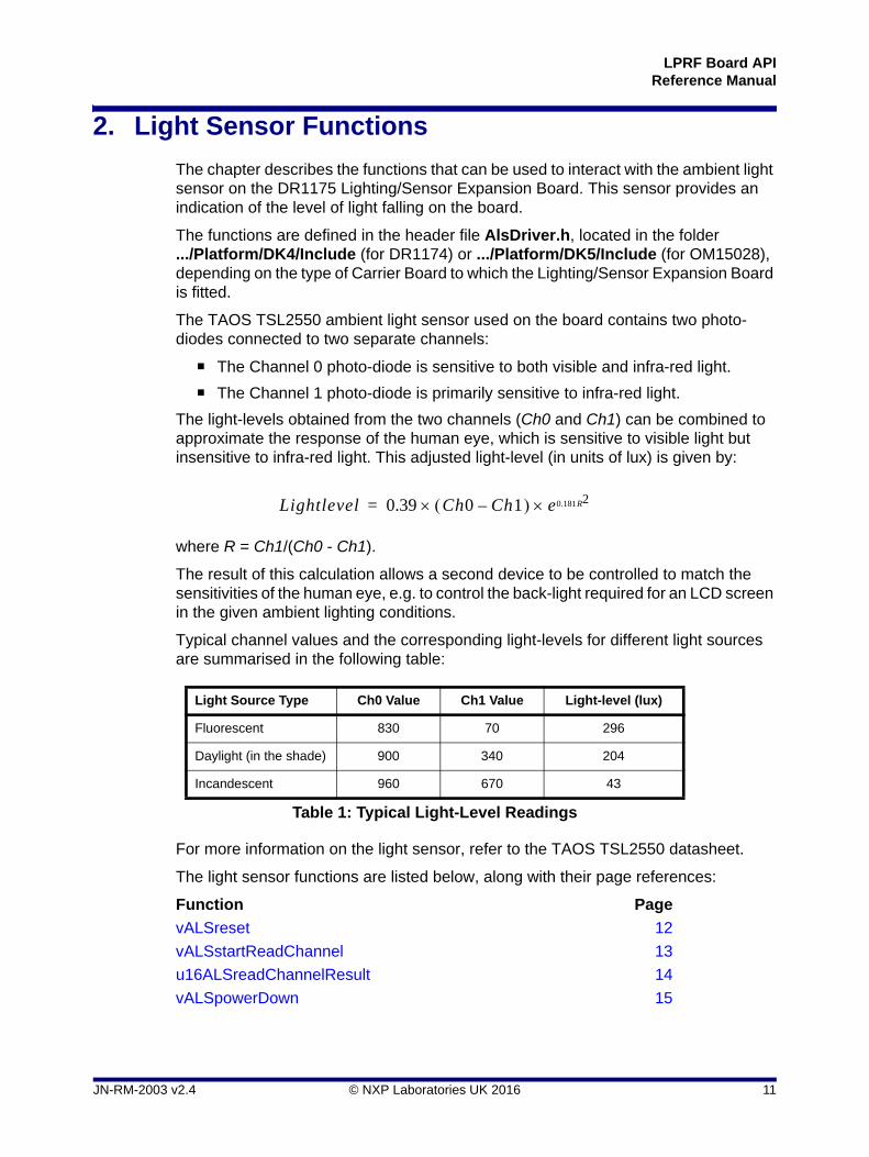
The chapter describes the functions that can be used to interact with the ambient light sensor on the DR1175 Lighting/Sensor Expansion Board. This sensor provides an indication of the level of light falling on the board.
The functions are defined in the header file AlsDriver.h, located in the folder .../Platform/DK4/Include (for DR1174) or .../Platform/DK5/Include (for OM15028), depending on the type of Carrier Board to which the Lighting/Sensor Expansion Board is fitted.
The TAOS TSL2550 ambient light sensor used on the board contains two photo-diodes connected to two separate channels:
The Channel 0 photo-diode is sensitive to both visible and infra-red light.
The Channel 1 photo-diode is primarily sensitive to infra-red light.
The light-levels obtained from the two channels (Ch0 and Ch1) can be combined to approximate the response of the human eye, which is sensitive to visible light but insensitive to infra-red light. This adjusted light-level (in units of lux) is given by:
where R = Ch1/(Ch0 - Ch1).
The result of this calculation allows a second device to be controlled to match the sensitivities of the human eye, e.g. to control the back-light required for an LCD screen in the given ambient lighting conditions.
Typical channel values and the corresponding light-levels for different light sources are summarised in the following table:
For more information on the light sensor, refer to the TAOS TSL2550 datasheet.
The light sensor functions are listed below, along with their page references:
Function Page
vALSreset 12
vALSstartReadChannel 13
u16ALSreadChannelResult 14
vALSpowerDown 15
Light Source Type Ch0 Value Ch1 Value Light-level (lux)
Fluorescent 830 70 296
Daylight (in the shade) 900 340 204
Incandescent 960 670 43
Table 1: Typical Light-Level Readings
Lightlevel 0.39 Ch0 Ch1– e 20.181R=
JN-RM-2003 v2.4 © NXP Laboratories UK 2016 11
Chapter 2Light Sensor Functions
vALSreset
Description
This function is used to initialise the ambient light sensor and must be called before using any other light sensor function.
Parameters
None
Returns
None
void vALSreset(void);
12 © NXP Laboratories UK 2016 JN-RM-2003 v2.4
LPRF Board APIReference Manual
vALSstartReadChannel
Description
This function can be used to initiate a read on one of the two channels (Channel 0 or Channel 1) of the ambient light sensor.
The result from the initiated read can be obtained by calling the function u16ALSreadChannelResult().
Parameters
u8Channel Channel to be read:
0 - Channel 01 - Channel 1
Returns
None
void vALSstartReadChannel(uint8 u8Channel);
Tip: In the Home Sensor Demonstration applications (supplied with some evaluation kits and available as Application Notes), only Channel 0 is used and after the first call to this function, the device continually restarts conversions (so there is no need to call it again).
JN-RM-2003 v2.4 © NXP Laboratories UK 2016 13
Chapter 2Light Sensor Functions
u16ALSreadChannelResult
Description
This function can be used to obtain the result of the last read of the ambient light sensor initiated by vALSstartReadChannel().
The returned result is a value in the range 0 to 4015.
Parameters
None
Returns
Integer value in the range 0 to 4015
uint16 u16ALSreadChannelResultvoid);
Note: The results of consecutive reads of Channel 0 and Channel 1 can be used to estimate the visible light-level as perceived by the human eye. This calculation is shown at the beginning of this chapter.
14 © NXP Laboratories UK 2016 JN-RM-2003 v2.4
LPRF Board APIReference Manual
vALSpowerDown
Description
This function can be used to power down the ambient light sensor unit.
The function is helpful in minimising the current drawn by the board - for example, it should be called on a board which acts as an End Device before entering sleep mode.
Parameters
None
Returns
None
void vALSpowerDown(void);
JN-RM-2003 v2.4 © NXP Laboratories UK 2016 15
Chapter 2Light Sensor Functions
16 © NXP Laboratories UK 2016 JN-RM-2003 v2.4
LPRF Board APIReference Manual
3. Temperature/Humidity Sensor Functions
The chapter describes the functions that can be used to interact with the temperature and humidity sensors on the DR1175 Lighting/Sensor Expansion Board:
Temperature can be measured in the range 0 to 124oC.
Relative humidity can be measured in the range 0-100%.
These two measurements are actually provided by a single sensor unit on the board.
The functions are defined in the header file HtsDriver.h, located in the folder .../Platform/DK4/Include (for DR1174) or .../Platform/DK5/Include (for OM15028), depending on the type of Carrier Board to which the Lighting/Sensor Expansion Board is fitted.
The temperature and humidity sensor functions are listed below, along with their page references:
Function Page
vHTSreset 18
vHTSstartReadTemp 19
u16HTSreadTempResult 20
vHTSstartReadHumidity 21
u16HTSreadHumidityResult 22
JN-RM-2003 v2.4 © NXP Laboratories UK 2016 17
Chapter 3Temperature/Humidity Sensor Functions
vHTSreset
Description
This function is used to initialise the combined temperature and humidity sensor, and must be called before using any other temperature and humidity function.
Parameters
None
Returns
None
void vHTSreset(void);
18 © NXP Laboratories UK 2016 JN-RM-2003 v2.4
LPRF Board APIReference Manual
vHTSstartReadTemp
Description
This function can be used to initiate a read of the temperature sensor.
The result from the initiated read can be obtained by calling the function u16HTSreadTempResult().
Parameters
None
Returns
None
void vHTSstartReadTemp(void);
JN-RM-2003 v2.4 © NXP Laboratories UK 2016 19
Chapter 3Temperature/Humidity Sensor Functions
u16HTSreadTempResult
Description
This function can be used to obtain the result of the last read of the temperature sensor initiated by vHTSstartReadTemp().
u16HTSreadTempResult() blocks until the result is available.
The returned result is a value in the range 0 to 124oC.
Parameters
None
Returns
Integer value in the range 0 to 124
uint16 u16HTSreadTempResult(void);
20 © NXP Laboratories UK 2016 JN-RM-2003 v2.4
LPRF Board APIReference Manual
vHTSstartReadHumidity
Description
This function can be used to initiate a read of the relative humidity sensor.
The result from the initiated read can be obtained by calling the function u16HTSreadHumidityResult().
Parameters
None
Returns
None
void vHTSstartReadHumidity(void);
JN-RM-2003 v2.4 © NXP Laboratories UK 2016 21
Chapter 3Temperature/Humidity Sensor Functions
u16HTSreadHumidityResult
Description
This function can be used to obtain the result of the last read of the relative humidity sensor initiated by vHTSstartReadHumidity().
u16HTSreadHumidityResult() blocks until the result is available.
The returned result is a value in the range 0-100%.
Parameters
None
Returns
Integer value in the range 0 to 100
uint16 u16HTSreadHumidityResult(void);
22 © NXP Laboratories UK 2016 JN-RM-2003 v2.4
LPRF Board APIReference Manual
4. LED Functions
The chapter describes the functions that can be used to control LEDs on a board. There are functions for two categories of controllable LED:
General LEDs controlled via JN51xx DIOs
RGB LEDs controlled via PCA9634 LED driver chip (DR1175 board only)
White LED cluster (DR1175 board only)
The functions for the above two LED categories are described below in Section 4.1 and Section 4.2 respectively.
4.1 General LED Functions
The functions described in this section can be used to control general-purpose LEDs via JN51xx DIOs. The controllable LEDs are located on the Carrier Board, as follows:
On the DR1174 Carrier Board, they are LEDs D3 and D6
On the OM15028 Carrier Board, they are LEDs D2 and D3
The functions are defined in the header file LedControl.h, located in the folder .../Platform/DK4/Include (for DR1174) or .../Platform/DK5/Include (for OM15028).
The General LED functions are listed below, along with their page references:
Function Page
vLedInitRfd 24
vLedInitFfd 25
vLedControl 26
JN-RM-2003 v2.4 © NXP Laboratories UK 2016 23
Chapter 4LED Functions
vLedInitRfd
Description
This function is used to initialise the two controllable LEDs on a Carrier Board and must be called before attempting to control the LEDs.
Parameters
None
Returns
None
void vLedInitRfd(void);
Tip: Either vLedInitRfd() or vLedInitFfd() can be used, as these functions perform identical operations for the DR1175 and OM15028 Carrier Boards. The two functions have been retained in the Board API for backward compatibility with older boards.
24 © NXP Laboratories UK 2016 JN-RM-2003 v2.4
LPRF Board APIReference Manual
vLedInitFfd
Description
This function is used to initialise the two controllable LEDs on a Carrier Board that and must be called before attempting to control the LEDs.
Parameters
None
Returns
None
void vLedInitFfd(void);
Tip: Either vLedInitFfd() or vLedInitRfd() can be used, as these functions perform identical operations for the DR1175 and OM15028 Carrier Boards. The two functions have been retained in the Board API for backward compatibility with older boards.
JN-RM-2003 v2.4 © NXP Laboratories UK 2016 25
Chapter 4LED Functions
vLedControl
Description
This function can be used to control (illuminate or extinguish) an individual LED.
Before using this function, the LED initialisation function vLedInitFfd() or vLedInitRfd() must have been called.
Parameters
u8Led LED to be controlled:
0 - D3 (on DR1174) or D2 (on OM15028)1 - D6 (on DR1174) or D3 (on OM15028)
bOn Action to be applied to LED:
TRUE - illuminate LEDFALSE - extinguish LED
Returns
None
void vLedControl(uint8 u8Led, bool_t bOn);
26 © NXP Laboratories UK 2016 JN-RM-2003 v2.4
LPRF Board APIReference Manual
4.2 RGB and White LED Functions (DR1175 only)
The DR1175 Lighting/Sensor Expansion Board features a variable-intensity RGB LED cluster and a variable-intensity White LED cluster.
The RGB LEDs are driven from a PCA9634 LED driver chip on the board. This driver has 8 channels, where channels 0, 1 and 2 control the blue, green and red LEDs, respectively (the remaining 5 channels can be used to drive PWM outputs on the header CN6).
The White LEDs are driven from the JN516x or JN517x device using the on-chip PWM Timers.
Functions are provided that allow the RGB and White LEDs to be controlled from an application running on a JN516x or JN517x device on the board. These functions are defined in the header files LightingBoard.h and pca9634.h. Depending on the type of the underlying Carrier Board, these files are located in the folder .../Platform/DK4/Include (for DR1174) or .../Platform/DK5/Include (for OM15028).
The LED functions are listed below, along with their page references:
Function Page
bRGB_LED_Enable 28
bRGB_LED_Disable 29
bRGB_LED_SetLevel 30
bRGB_LED_On 31
bRGB_LED_Off 32
bRGB_LED_SetGroupLevel 33
bPCA9634_Init 34
bPCA9634_SetChannelLevel 35
bPCA9634_SetGroupLevel 36
bWhite_LED_Enable 37
bWhite_LED_Disable 38
bWhite_LED_SetLevel 39
bWhite_LED_On 40
bWhite_LED_Off 41
Caution: The LEDs on the DR1175 board are very bright at maximum intensity. To avoid damage to your eyes, do not look into them directly for an extended period of time.
JN-RM-2003 v2.4 © NXP Laboratories UK 2016 27
Chapter 4LED Functions
bRGB_LED_Enable
Description
This function is used to initialise the PCA9634 LED driver device.
This function must be called before using any of the other RGB LED functions.
Parameters
None
Returns
TRUE - driver successfully initialised
FALSE - driver failed to initialise
bool bRGB_LED_Enable(void);
28 © NXP Laboratories UK 2016 JN-RM-2003 v2.4
LPRF Board APIReference Manual
bRGB_LED_Disable
Description
This function is used to disable the PCA9634 LED driver device.
Parameters
None
Returns
TRUE - driver successfully disabled
FALSE - driver failed to disable
bool bRGB_LED_Disable(void);
JN-RM-2003 v2.4 © NXP Laboratories UK 2016 29
Chapter 4LED Functions
bRGB_LED_SetLevel
Description
This function can be used to set the RGB LED brightness level in the range 0 (dimmest) to 255 (brightest).
Parameters
u8RedLevel Red brightness level (0-255)
u8GreenLevel Green brightness level (0-255)
u8BlueLevel Blue brightness level (0-255)
Returns
TRUE - success
FALSE - fail
bool bRGB_LED_SetLevel(uint8 u8RedLevel,uint8 u8GreenLevel,uint8 u8BlueLevel);
30 © NXP Laboratories UK 2016 JN-RM-2003 v2.4
LPRF Board APIReference Manual
bRGB_LED_On
Description
This function can be used to switch on the RGB LEDs. The RGB LED brightness levels will be set to the values previously configured using bRGB_LED_SetLevel().
Parameters
None
Returns
TRUE - success
FALSE - fail
bool bRGB_LED_On(void);
JN-RM-2003 v2.4 © NXP Laboratories UK 2016 31
Chapter 4LED Functions
bRGB_LED_Off
Description
This function can be used to switch off the RGB LEDs.
Parameters
None
Returns
TRUE - success
FALSE - fail
bool bRGB_LED_Off(void);
32 © NXP Laboratories UK 2016 JN-RM-2003 v2.4
LPRF Board APIReference Manual
bRGB_LED_SetGroupLevel
Description
This function can be used to apply a global scaling factor (of less than or equal to 1) across all channels of the PCA9634 LED driver device on the DR1175 board. This allows the brightnesses of the LEDs of the RGB cluster to be scaled simultaneously by the same factor. The scaling factor parameter u8Level can be set to a value in the range 0 to 255. Once the function has been called, the brightness of each LED becomes u8Level/255 of its original brightness (the brightness with no global scaling factor applied). The default value of u8Level is 255, corresponding to full brightness. A factor of 0 will extinguish the LEDs.
This feature is useful when the LEDs of the RGB cluster are set to different brightness levels in order to achieve a certain colour. The function allows the brightness of the LED cluster to be adjusted without affecting this colour.
Note that when calling the function multiple times, on each occasion the scaling factor is applied to the original brightness levels of the LED cluster. For example, calling the function first with a scaling factor of 128 will result in a brightness reduction to approximately 50% of the original brightness. Then calling the function again with a scaling factor of 192 will result in a brightness increase to approximately 75% of the original brightness.
Also note that the scaling factor is applied to channels 3-7 of the PCA9634 driver device (that may drive PWM outputs on header CN6), as well as to channels 0-2 used for the RGB cluster.
Parameters
u8Level Brightness scaling factor in the range 0 to 255
Returns
TRUE - success
FALSE - fail
bool bRGB_LED_SetGroupLevel(uint8 u8Level);
JN-RM-2003 v2.4 © NXP Laboratories UK 2016 33

Chapter 4LED Functions
bPCA9634_Init
Description
This function is used to initialise the PCA9634 LED driver device and must be called before the RGB LED cluster on the DR1175 board can be controlled using any of the other RGB LED functions.
Parameters
None
Returns
One of:
TRUE - driver successfully initialised
FALSE - driver failed to initialise
bool bPCA9634_Init(void);
Note: The function bRGB_LED_Enable() is identical to bPCA9634_Init() and may be called instead of this one.
34 © NXP Laboratories UK 2016 JN-RM-2003 v2.4
LPRF Board APIReference Manual
bPCA9634_SetChannelLevel
Description
This function can be used to control one of the RGB LEDs on the DR1175 board by setting the brightness level for the LED, in the range 0 (dimmest) to 255 (brightest).
The function requires the relevant channel number for the LED, which must be 0 (blue), 1 (green) or 2 (red) for the RGB LED cluster. If another channel is specified (3-7) then the level of the relevant output will be set (if connected).
Parameters
u8Channel LED channel to be controlled, in the range 0-7 (where 0, 1, 2 correspond to the blue, green and red LEDs, respectively)
u8Level Brightness level to which specified LED is to be set, in the range 0-255
Returns
One of:
TRUE - brightness level successfully set
FALSE - brightness level not set
bool bPCA9634_SetChannelLevel(uint8 u8Channel, uint8 u8Level);
Note: The brightness level for the RGB channels may instead be set using a single call to function bRGB_LED_SetLevel().
JN-RM-2003 v2.4 © NXP Laboratories UK 2016 35
Chapter 4LED Functions
bPCA9634_SetGroupLevel
Description
This function can be used to apply a global scaling factor (of less than or equal to 1) across all channels of the PCA9634 LED driver device on the DR1175 board. This allows the brightnesses of the LEDs of the RGB cluster to be scaled simultaneously by the same factor. The scaling factor parameter u8Level can be set to a value in the range 0 to 255. Once the function has been called, the brightness of each LED becomes u8Level/255 of its original brightness (the brightness with no global scaling factor applied). The default value of u8Level is 255, corresponding to full brightness. A factor of 0 will extinguish the LEDs.
This feature is useful when the LEDs of the RGB cluster are set to different brightness levels in order to achieve a certain colour. The function allows the brightness of the LED cluster to be adjusted without affecting this colour.
Note that when calling the function multiple times, on each occasion the scaling factor is applied to the original brightness levels of the LED cluster. For example, calling the function first with a scaling factor of 128 will result in a brightness reduction to approximately 50% of the original brightness. Then calling the function again with a scaling factor of 192 will result in a brightness increase to approximately 75% of the original brightness.
Also note that the scaling factor is applied to channels 3-7 of the PCA9634 driver device (that may drive PWM outputs on header CN6), as well as to channels 0-2 used for the RGB cluster.
Parameters
u8Level Brightness scaling factor in the range 0 to 255
Returns
One of:
TRUE - scaling factor successfully applied
FALSE - scaling factor not applied
bool bPCA9634_SetGroupLevel(uint8 u8Level);
Note: The function bRGB_LED_SetGroupLevel() is identical to bPCA9634_SetGroupLevel() and may be called instead of this one.
36 © NXP Laboratories UK 2016 JN-RM-2003 v2.4
LPRF Board APIReference Manual
bWhite_LED_Enable
Description
This function is used to initialise the PWM Timers and DIO for driving the White LED cluster. This function must be called before using any other White LED cluster function.
Parameters
None
Returns
TRUE - success
FALSE - fail
bool bWhite_LED_Enable(void);
JN-RM-2003 v2.4 © NXP Laboratories UK 2016 37
Chapter 4LED Functions
bWhite_LED_Disable
Description
This function is used to disable control of the White LED cluster.
Parameters
None
Returns
TRUE - success
FALSE - fail
bool bWhite_LED_Disable(void);
38 © NXP Laboratories UK 2016 JN-RM-2003 v2.4
LPRF Board APIReference Manual
bWhite_LED_SetLevel
Description
This function can be used to set the White LED brightness level in the range 0 (dimmest) to 255 (brightest).
Parameters
u8BrightnessLevel Brightness level (0-255)
Returns
TRUE - success
FALSE - fail
bool bWhite_LED_SetLevel(uint8 u8BrightnessLevel);
JN-RM-2003 v2.4 © NXP Laboratories UK 2016 39
Chapter 4LED Functions
bWhite_LED_On
Description
This function can be used to switch on the White LED cluster. The White LED brightness level will be set to the value previously configured using bWhite_LED_SetLevel().
Parameters
None
Returns
TRUE - success
FALSE - fail
bool bWhite_LED_On(void);
40 © NXP Laboratories UK 2016 JN-RM-2003 v2.4
LPRF Board APIReference Manual
bWhite_LED_Off
Description
This function can be used to switch off the White LED cluster.
Parameters
None
Returns
TRUE - success
FALSE - fail
bool bWhite_LED_Off(void);
JN-RM-2003 v2.4 © NXP Laboratories UK 2016 41

Chapter 4LED Functions
42 © NXP Laboratories UK 2016 JN-RM-2003 v2.4
LPRF Board APIReference Manual
5. Button Functions
The chapter describes the functions that can be used to interact with a general-purpose button on a Carrier Board:
On DR1174, this button is SW1 but labelled DIO8 on the board
On OM15028, this button is SW2 but also labelled GPIO4 on the board
The above boards also have a reset button that cannot be accessed by these functions.
The functions are defined in the header file Button.h, located in the folder .../Platform/DK4/Include (for DR1174) or .../Platform/DK5/Include (for OM15028).
The button functions are listed below, along with their page references:
Function Page
vButtonInitRfd 44
vButtonInitFfd 45
u8ButtonReadRfd 46
u8ButtonReadFfd 47
Note: The four buttons SW1-SW4 on an LCD Expansion Board and on a Generic Expansion Board (which can be mounted on a carrier board) require their own sets of functions, which are detailed in Chapter 6 and Chapter 7 respectively.
JN-RM-2003 v2.4 © NXP Laboratories UK 2016 43
Chapter 5Button Functions
vButtonInitRfd
Description
This function is used to initialise the general-purpose button on a Carrier Board and must be called before attempting to access the button.
Parameters
None
Returns
None
void vButtonInitRfd(void);
Tip: Either vButtonInitRfd() or vButtonInitFfd() can be used, as these functions perform identical operations for the DR1175 and OM15028 Carrier Boards. The two functions have been retained in the Board API for backward compatibility with older boards.
Note: Different initialisation functions must be used for the four buttons on an LCD Expansion Board and Generic Expansion Board - these functions are vLcdButtonInit() and vGenericButtonInit(), described on pages 75 and 81 respectively.
44 © NXP Laboratories UK 2016 JN-RM-2003 v2.4
LPRF Board APIReference Manual
vButtonInitFfd
Description
This function is used to initialise the general-purpose button on a Carrier Board and must be called before attempting to access the button.
Parameters
None
Returns
None
void vButtonInitFfd(void);
Tip: Either vButtonInitFfd() or vButtonInitRfd() can be used, as these functions perform identical operations for the DR1175 and OM15028 Carrier Boards. The two functions have been retained in the Board API for backward compatibility with older boards.
Note: Different initialisation functions must be used for the four buttons on an LCD Expansion Board and Generic Expansion Board - these functions are vLcdButtonInit() and vGenericButtonInit(), described on pages 75 and 81 respectively.
JN-RM-2003 v2.4 © NXP Laboratories UK 2016 45
Chapter 5Button Functions
u8ButtonReadRfd
Description
This function can be used to obtain the current state of the general-purpose button on a Carrier Board (SW1/DIO8 on DR1174 or SW2/GPIO4 on OM15028).
The state (pressed or not pressed) of the button is returned in a single bitmap. To obtain the state of button, the returned bitmap must be logical-ANDed with the mask BUTTON_0_MASK. A non-zero result indicates that the button is pressed and a zero result indicates that it is not pressed.
Note that there is no de-bounce circuit or algorithm employed.
Before using this function, the button initialisation function vButtonInitFfd() or vButtonInitRfd() must have been called.
Parameters
None
Returns
Bitmap containing the state of the button (see above)
uint8 u8ButtonReadRfd(void);
Tip: Either u8ButtonReadRfd() or u8ButtonReadFfd() can be used, as these functions perform identical operations for the DR1175 and OM15028 Carrier Boards. The two functions have been retained in the Board API for backward compatibility with older boards.
46 © NXP Laboratories UK 2016 JN-RM-2003 v2.4
LPRF Board APIReference Manual
u8ButtonReadFfd
Description
This function can be used to obtain the current state of the general-purpose button on a Carrier Board (SW1/DIO8 on DR1174 or SW2/GPIO4 on OM15028).
The state (pressed or not pressed) of the button is returned in a single bitmap. To obtain the state of button, the returned bitmap must be logical-ANDed with the mask BUTTON_0_MASK. A non-zero result indicates that the button is pressed and a zero result indicates that it is not pressed.
Note that there is no de-bounce circuit or algorithm employed.
Before using this function, the button initialisation function vButtonInitFfd() or vButtonInitRfd() must have been called.
Parameters
None
Returns
Bitmap containing the state of the button (see above)
uint8 u8ButtonReadFfd(void);
Tip: Either u8ButtonReadFfd() or u8ButtonReadRfd() can be used, as these functions perform identical operations for the DR1175 and OM15028 Carrier Boards. The two functions have been retained in the Board API for backward compatibility with older boards.
JN-RM-2003 v2.4 © NXP Laboratories UK 2016 47

Chapter 5Button Functions
48 © NXP Laboratories UK 2016 JN-RM-2003 v2.4
LPRF Board APIReference Manual
6. LCD Screen Functions
The chapter describes the functions that can be used to interact with the LCD screen on a DR1201 or DR1215 LCD Expansion Board (both now discontinued).
The functions are defined in the header file LcdDriver.h, located in the folder .../Platform/DK4/Include (for DR1174) or .../Platform/DK5/Include (for OM15028), depending on the type of Carrier Board to which the LCD Expansion Board is fitted.
LCD screen functions that are common to all boards are defined in the header files LcdDraw.h and LcdExtras.h which are located in the folder .../Platform/Common/Include.
6.1 LCD Screen and Data Display
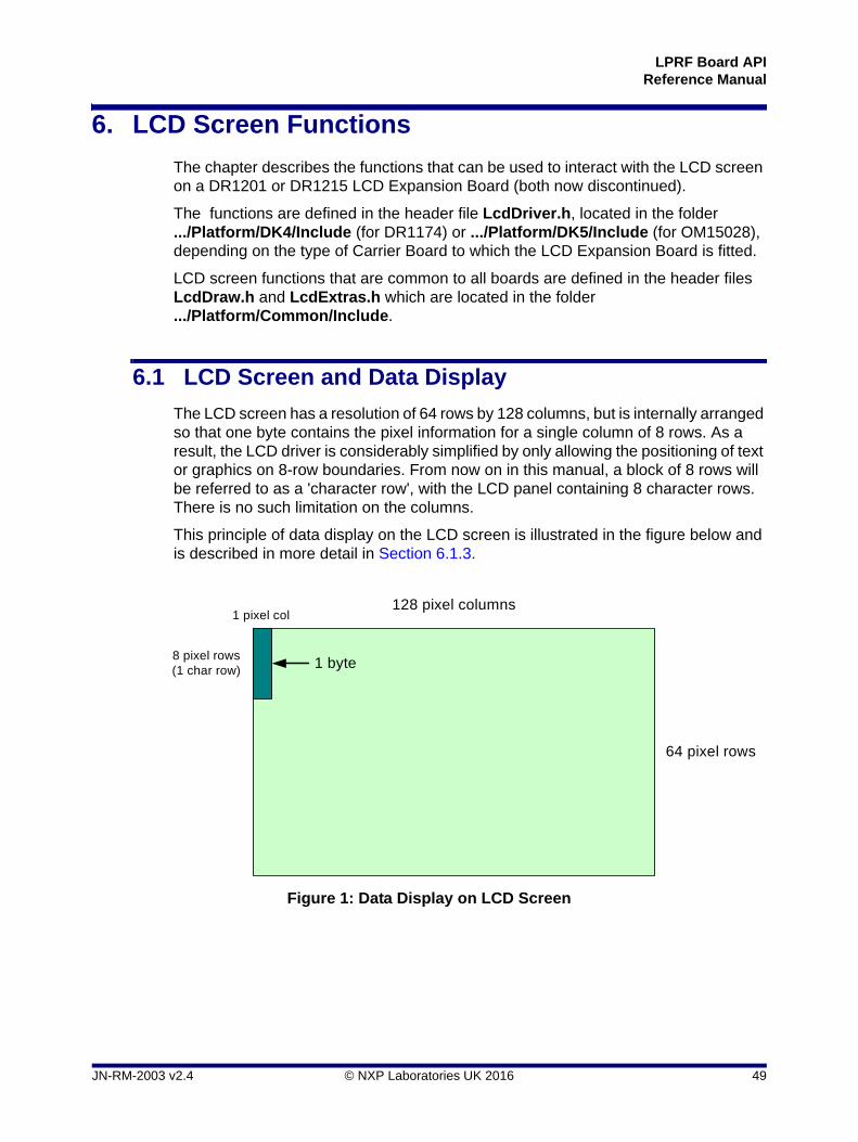
The LCD screen has a resolution of 64 rows by 128 columns, but is internally arranged so that one byte contains the pixel information for a single column of 8 rows. As a result, the LCD driver is considerably simplified by only allowing the positioning of text or graphics on 8-row boundaries. From now on in this manual, a block of 8 rows will be referred to as a 'character row', with the LCD panel containing 8 character rows. There is no such limitation on the columns.
This principle of data display on the LCD screen is illustrated in the figure below and is described in more detail in Section 6.1.3.
Figure 1: Data Display on LCD Screen
128 pixel columns
64 pixel rows
8 pixel rows(1 char row)
1 pixel col
1 byte
JN-RM-2003 v2.4 © NXP Laboratories UK 2016 49
Chapter 6LCD Screen Functions
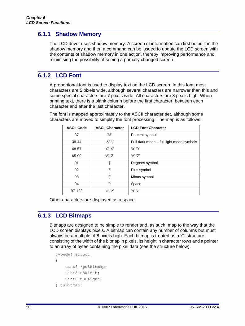
6.1.1 Shadow Memory
The LCD driver uses shadow memory. A screen of information can first be built in the shadow memory and then a command can be issued to update the LCD screen with the contents of shadow memory in one action, thereby improving performance and minimising the possibility of seeing a partially changed screen.
6.1.2 LCD Font
A proportional font is used to display text on the LCD screen. In this font, most characters are 5 pixels wide, although several characters are narrower than this and some special characters are 7 pixels wide. All characters are 8 pixels high. When printing text, there is a blank column before the first character, between each character and after the last character.
The font is mapped approximately to the ASCII character set, although some characters are moved to simplify the font processing. The map is as follows:
Other characters are displayed as a space.
6.1.3 LCD Bitmaps
Bitmaps are designed to be simple to render and, as such, map to the way that the LCD screen displays pixels. A bitmap can contain any number of columns but must always be a multiple of 8 pixels high. Each bitmap is treated as a 'C' structure consisting of the width of the bitmap in pixels, its height in character rows and a pointer to an array of bytes containing the pixel data (see the structure below).
typedef struct
{
uint8 *pu8Bitmap;
uint8 u8Width;
uint8 u8Height;
} tsBitmap;
ASCII Code ASCII Character LCD Font Character
37 ‘%’ Percent symbol
38-44 ‘&’-‘,’ Full dark moon – full light moon symbols
48-57 ‘0’-‘9’ ‘0’-‘9’
65-90 ‘A’-‘Z’ ‘A’-‘Z’
91 ‘[‘ Degrees symbol
92 ‘\’ Plus symbol
93 ‘]’ Minus symbol
94 ‘^’ Space
97-122 ‘a’-‘z’ ‘a’-‘z’
50 © NXP Laboratories UK 2016 JN-RM-2003 v2.4
LPRF Board APIReference Manual
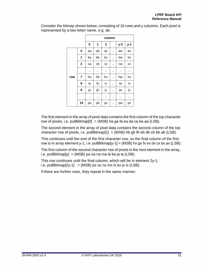
Consider the bitmap shown below, consisting of 16 rows and y columns. Each pixel is represented by a two-letter name, e.g. ab.
The first element in the array of pixel data contains the first column of the top character row of pixels, i.e. pu8Bitmap[0] = (MSB) ha ga fa ea da ca ba aa (LSB).
The second element in the array of pixel data contains the second column of the top character row of pixels, i.e. pu8Bitmap[1] = (MSB) hb gb fb eb db cb bb ab (LSB).
This continues until the end of the first character row, so the final column of the first row is in array element y-1, i.e. pu8Bitmap[y-1] = (MSB) hx gx fx ex dx cx bx ax (LSB).
The first column of the second character row of pixels is the next element in the array, i.e. pu8Bitmap[y] = (MSB) pa oa na ma la ka ja ia (LSB).
This row continues until the final column, which will be in element 2y-1, i.e. pu8Bitmap[2y-1] = (MSB) px ox nx mx lx kx jx ix (LSB).
If there are further rows, they repeat in the same manner.
column
0 1 2 y-2 y-1
row
0 aa ab ac .. aw ax
1 ba bb bc .. bw bx
2 ca cb cc .. cw cx
.. .. .. .. .. ..
7 ha hb hc .. hw hx
8 ia ib ic .. iw ix
9 ja jb jc .. jw jx
.. .. .. .. .. ..
15 pa pb pc .. pw px
JN-RM-2003 v2.4 © NXP Laboratories UK 2016 51
Chapter 6LCD Screen Functions
6.2 Functions
The LCD screen functions are listed below, along with their page references:
Function Page
vLcdResetDefault 53
vLcdReset 54
vLcdStop 55
vLcdClear 56
vLcdWriteText 57
vLcdWriteTextRightJustified 58
vLcdWriteInvertedText 59
vLcdWriteBitmap 60
vLcdPlotPoint 61
bLcdGetPixel 62
vLcdDrawLine 63
vLcdDrawCircle 64
vLcdFloodFill 65
vLcdRefreshAll 66
vLcdRefreshArea 67
vLcdContrastLevel 68
u8LcdCalcContrastLevel 69
vLcdBackLightEnable 70
vLcdGrabSpiBus 71
vLcdFreeSpiBus 72
vLcdPowerOff 73
vLcdPowerSavingMode 74
vLcdButtonInit 75
u8LcdButtonRead 76
Note: The above function set includes functions to interact with the four buttons (SW1-SW4) on an LCD Expansion Board. These buttons do not require the Button functions described in Chapter 5.
52 © NXP Laboratories UK 2016 JN-RM-2003 v2.4
LPRF Board APIReference Manual
vLcdResetDefault
Description
This function is used to initialise the LCD panel using default settings for bias and gain, which should give a good level of contrast. The LCD screen is also cleared.
Alternatively, the LCD panel can be initialised with custom settings for bias and gain using the function vLcdReset().
Parameters
None
Returns
None
void vLcdResetDefault(void);
JN-RM-2003 v2.4 © NXP Laboratories UK 2016 53
Chapter 6LCD Screen Functions
vLcdReset
Description
This function is used to initialise the LCD panel using the specified settings for bias and gain. The LCD screen is also cleared.
Alternatively, the LCD panel can be initialised with the default settings for bias and gain using the function vLcdResetDefault().
Parameters
u8Bias Bias value to use, in the range 0-3
u8Gain Gain value to use, in the range 0-3
Returns
None
void vLcdReset(uint8 u8Bias, uint8 u8Gain);
54 © NXP Laboratories UK 2016 JN-RM-2003 v2.4
LPRF Board APIReference Manual
vLcdStop
Description
This function can be used to power off the LCD screen. The function is normally only used before shutting down the Carrier Board, in order to allow the LCD screen to discharge itself properly.
Parameters
None
Returns
None
void vLcdStop(void);
JN-RM-2003 v2.4 © NXP Laboratories UK 2016 55
Chapter 6LCD Screen Functions
vLcdClear
Description
This function can be used to clear the shadow memory of any text or graphics. However, the function does not update the LCD screen itself.
To update the LCD screen from the shadow memory, you can use the function vLcdResfreshAll() or vLcdRefreshArea().
Parameters
None
Returns
None
void vLcdClear(void);
56 © NXP Laboratories UK 2016 JN-RM-2003 v2.4
LPRF Board APIReference Manual
vLcdWriteText
Description
This function can be used to write text to the shadow memory.
The text is left-justified, starting at the row and column specified. No attempt is made to prevent the text from spilling over the end of the specified row and if this occurs, the text will wrap around to the next row.
To update the LCD screen from the shadow memory, you can use the function vLcdResfreshAll() or vLcdRefreshArea().
Parameters
*pcString Null-terminated text string to display
u8Row Character row on which to display text (in the range 0-7)
u8Column Column in which to start displaying text (in the range 0-127)
Returns
None
void vLcdWriteText(char *pcString, uint8 u8Row, uint8 u8Column);
JN-RM-2003 v2.4 © NXP Laboratories UK 2016 57
Chapter 6LCD Screen Functions
vLcdWriteTextRightJustified
Description
This function can be used to write text to the shadow memory.
The text is right-justified, finishing at the row and column specified. No attempt is made to prevent the text from spilling over the start of the specified row and if this occurs, the text will wrap around to the previous row.
To update the LCD screen from the shadow memory, you can use the function vLcdResfreshAll() or vLcdRefreshArea().
Parameters
*pcString Null-terminated text string to display
u8Row Character row on which to display text (in the range 0-7)
u8Column Column in which to finish displaying text (in the range 0-127)
Returns
None
void vLcdWriteTextRightJustified(char *pcString, uint8 u8Row, uint8 u8EndColumn);
58 © NXP Laboratories UK 2016 JN-RM-2003 v2.4
LPRF Board APIReference Manual
vLcdWriteInvertedText
Description
This function can be used to write inverted text (pixel colours reversed) to the shadow memory.
The text is left-justified, starting at the row and column specified. No attempt is made to prevent the text from spilling over the end of the specified row and if this occurs, the text will wrap around to the next row.
To update the LCD screen from the shadow memory, you can use the function vLcdResfreshAll() or vLcdRefreshArea().
Parameters
*pcString Null-terminated text string to display
u8Row Character row on which to display text (in the range 0-7)
u8Column Column in which to start displaying text (in the range 0-127)
Returns
None
void vLcdWriteInvertedText(char *pcString, uint8 u8Row, uint8 u8Column);
JN-RM-2003 v2.4 © NXP Laboratories UK 2016 59
Chapter 6LCD Screen Functions
vLcdWriteBitmap
Description
This function can be used to put the specified bitmap into the shadow memory at the specified screen location. If the bitmap goes past the edge of the display area, it is truncated.
To update the LCD screen from the shadow memory, you can use the function vLcdResfreshAll() or vLcdRefreshArea().
Parameters
*psBitmap Pointer to structure containing bitmap information
u8LeftColumn Left-most column of bitmap (in the range 0-127)
u8TopRow First character row of bitmap (in the range 0-7)
Returns
None
void vLcdWriteBitmap(tsBitmap *psBitmap, uint8 u8LeftColumn, uint8 u8TopRow);
60 © NXP Laboratories UK 2016 JN-RM-2003 v2.4
LPRF Board APIReference Manual
vLcdPlotPoint
Description
This function can be used to plot a point in the shadow memory at the pixel with the specified screen coordinates (x,y). If either x or y is out of range, the pixel cannot be plotted.
To update the LCD screen from the shadow memory, you can use the function vLcdResfreshAll() or vLcdRefreshArea().
Parameters
u8X x-coordinate of pixel to be plotted (in the range 0-127)
u8Y y-coordinate of pixel to be plotted (in the range 0-63)
Returns
None
void vLcdPlotPoint(uint8 u8X, uint8 u8Y);
JN-RM-2003 v2.4 © NXP Laboratories UK 2016 61
Chapter 6LCD Screen Functions
bLcdGetPixel
Description
This function can be used to obtain the status of the pixel at the specified screen coordinates (x,y) in the shadow memory - that is, whether a point has been plotted at the pixel location. If either x or y is out of range, the function returns FALSE.
Parameters
u8X x-coordinate of pixel to be checked (in the range 0-127)
u8Y y-coordinate of pixel to be checked (in the range 0-63)
Returns
TRUE - point plotted at pixel location
FALSE - point not plotted at pixel location or invalid screen location specified
bool_t bLcdGetPixel(uint8 u8X, uint8 u8Y);
62 © NXP Laboratories UK 2016 JN-RM-2003 v2.4
LPRF Board APIReference Manual
vLcdDrawLine
Description
This function can be used to draw a straight line between two specified screen locations in the shadow memory.
The end-points of the line are specified in terms of coordinates (x1,y1) and (x2,y2). The line is clipped if either of these points lies outside the screen area.
To update the LCD screen from the shadow memory, you can use the function vLcdResfreshAll() or vLcdRefreshArea().
Parameters
u8x1 x-coordinate of first end-point of line (in the range 0-127)
u8y1 y-coordinate of first end-point of line (in the range 0-63)
u8x2 x-coordinate of second end-point of line (in the range 0-127)
u8y2 y-coordinate of second end-point of line (in the range 0-63)
Returns
None
void vLcdDrawLine(uint8 u8x1, uint8 u8y1, uint8 u8x2, uint8 u8y2);
JN-RM-2003 v2.4 © NXP Laboratories UK 2016 63
Chapter 6LCD Screen Functions
vLcdDrawCircle
Description
This function can be used to draw the circle with specified centre and radius in the shadow memory.
The centre of the circle is specified in terms of coordinates (Xc,Yc). The circle is clipped if any points on its circumference lie outside the screen area.
To update the LCD screen from the shadow memory, you can use the function vLcdResfreshAll() or vLcdRefreshArea().
Parameters
Xc x-coordinate of circle centre (in the range 0-127)
Yc y-coordinate of circle centre (in the range 0-63)
Radius Radius of circle, in pixels
Returns
None
void vLcdDrawCircle(int Xc, int Yc, int Radius);
64 © NXP Laboratories UK 2016 JN-RM-2003 v2.4
LPRF Board APIReference Manual
vLcdFloodFill
Description
This function can be used to perform a ‘flood fill’ of a screen region in shadow memory - that is, all pixels within the region will be plotted (black).
The region to be filled must have been pre-defined as a closed boundary - for example, a circle created using the vLcdDrawCircle() function. vLcdFloodFill() requires any starting point to be specified inside but not on the boundary. If the boundary is not closed, the fill will 'leak' and corrupt the display.
To update the LCD screen from the shadow memory, you can use the function vLcdResfreshAll() or vLcdRefreshArea().
Parameters
i32x x-coordinate of starting point (in the range 0-127)
i32y y-coordinate of starting point (in the range 0-63)
Returns
None
void vLcdFloodFill(int i32x, int i32y);
JN-RM-2003 v2.4 © NXP Laboratories UK 2016 65
Chapter 6LCD Screen Functions
vLcdRefreshAll
Description
This function can be used to copy the contents of shadow memory to the LCD panel and therefore to refresh the entire screen contents. This copy takes approximately 4.5 ms.
Alternatively, to update a rectangular portion of the LCD screen from the shadow memory, use the function vLcdRefreshArea().
Parameters
None
Returns
None
void vLcdRefreshAll(void);
66 © NXP Laboratories UK 2016 JN-RM-2003 v2.4
LPRF Board APIReference Manual
vLcdRefreshArea
Description
This function can be used to copy the contents of the specified rectangle in shadow memory to the appropriate part of the LCD screen without disturbing the rest of the display.
The rectangular screen area to refresh is specified in terms of the left-most column, the top row, the width and the height of the rectangle.
Alternatively, to update the entire LCD screen from shadow memory, use the function vLcdRefreshAll().
Parameters
u8LeftColumn Left-most column of rectangle (in the range 0-127)
u8TopRow First character row of rectangle (in the range 0-7)
u8Width Number of columns in width of rectangle (in the range 1-128)
u8Height Number of rows in height of rectangle (in the range 1-8)
Returns
None
void vLcdRefreshArea(uint8 u8LeftColumn, uint8 u8TopRow, uint8 u8Width, uint8 u8Height);
JN-RM-2003 v2.4 © NXP Laboratories UK 2016 67
Chapter 6LCD Screen Functions
vLcdContrastLevel
Description
This function can be used to control the contrast level of the LCD screen.
Parameters
u8Gain Contrast level (in the range 0-15 maximum)
Returns
None
void vLcdContrastLevel(uint8 u8Gain);
68 © NXP Laboratories UK 2016 JN-RM-2003 v2.4
LPRF Board APIReference Manual
u8LcdCalcContrastLevel
Description
This function can be used to calculate the correct contrast level required for the LCD screen. The correct LCD contrast level may then be subsequently set by using the return value of this function as the input paramater value in the call to function vLCDContrastLevel().
Parameters
None
Returns
Contrast level (in the range 0-15)
uint8 u8LcdCalcContrastLevel(void);
JN-RM-2003 v2.4 © NXP Laboratories UK 2016 69
Chapter 6LCD Screen Functions
vLcdBackLightEnable
Description
This function can be used to control the LCD back-light.
Parameters
u8Status 0 - Disable (switch off) the LCD back-light
1 - Enable (switch on) the LCD back-light
Note, all other values will have no effect.
Returns
None
void vLcdBackLightEnable(uint8 u8Status);
70 © NXP Laboratories UK 2016 JN-RM-2003 v2.4
LPRF Board APIReference Manual
vLcdGrabSpiBus
Description
This function can be used to take control of the SPI bus for the LCD panel.
Parameters
None
Returns
None
void vLcdGrabSpiBus(void);
JN-RM-2003 v2.4 © NXP Laboratories UK 2016 71
Chapter 6LCD Screen Functions
vLcdFreeSpiBus
Description
This function can be used to free control of the SPI bus for the LCD panel.
Parameters
None
Returns
None
void vLcdFreeSpiBus(void);
72 © NXP Laboratories UK 2016 JN-RM-2003 v2.4
LPRF Board APIReference Manual
vLcdPowerOff
Description
This function can be used to power off the LCD screen. The function is normally only used before shutting down the LCD screen of the LCD Expansion Board, in order to allow the LCD screen to discharge itself properly.
Parameters
None
Returns
None
void vLcdPowerOff(void);
JN-RM-2003 v2.4 © NXP Laboratories UK 2016 73
Chapter 6LCD Screen Functions
vLcdPowerSavingMode
Description
This function can be used to control the LCD screen power-saving mode.
Parameters
bSelectMode TRUE - Power-saving mode ON
FALSE - Power-saving mode OFF
Returns
None
void vLcdPowerSavingMode(bool_t bSelectMode);
74 © NXP Laboratories UK 2016 JN-RM-2003 v2.4
LPRF Board APIReference Manual
vLcdButtonInit
Description
This function can be used to initialise access to the four buttons (SW1-SW4) on the LCD Expansion Board (DR1215 or DR1201).
Parameters
None
Returns
None
void vLcdButtonInit(void);
Note: Access to the general-purpose button on the underlying Carrier Board (DR1174 or OM15028) can be initialised using the function vButtonInitFfd() or vButtonInitRfd(), described in Chapter 5.
JN-RM-2003 v2.4 © NXP Laboratories UK 2016 75
Chapter 6LCD Screen Functions
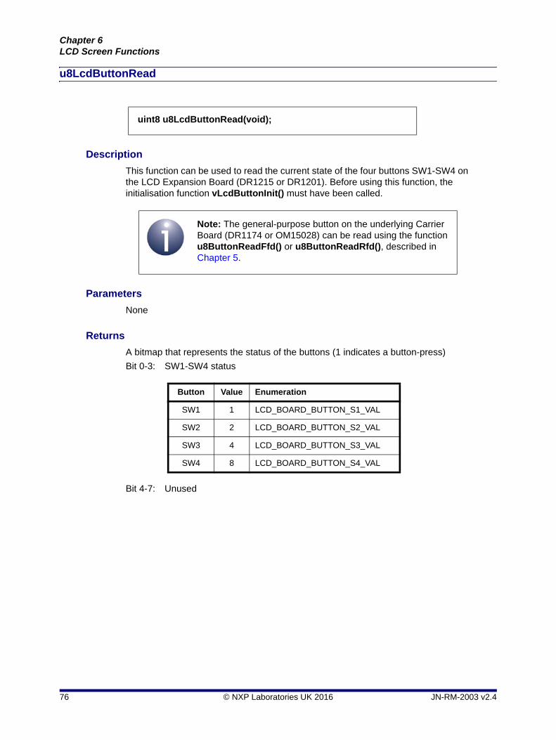
u8LcdButtonRead
Description
This function can be used to read the current state of the four buttons SW1-SW4 on the LCD Expansion Board (DR1215 or DR1201). Before using this function, the initialisation function vLcdButtonInit() must have been called.
Parameters
None
Returns
A bitmap that represents the status of the buttons (1 indicates a button-press)
Bit 0-3: SW1-SW4 status
Bit 4-7: Unused
uint8 u8LcdButtonRead(void);
Note: The general-purpose button on the underlying Carrier Board (DR1174 or OM15028) can be read using the function u8ButtonReadFfd() or u8ButtonReadRfd(), described in Chapter 5.
Button Value Enumeration
SW1 1 LCD_BOARD_BUTTON_S1_VAL
SW2 2 LCD_BOARD_BUTTON_S2_VAL
SW3 4 LCD_BOARD_BUTTON_S3_VAL
SW4 8 LCD_BOARD_BUTTON_S4_VAL
76 © NXP Laboratories UK 2016 JN-RM-2003 v2.4
LPRF Board APIReference Manual
7. Generic Board (DR1199) Functions
This chapter describes the functions that can be used to interact with the specific resources provided by the DR1199 Generic Expansion Board.
The Generic Expansion Board provides the following resources:
50kohm potentiometer (R4)
4 x push-button (SW1-SW4)
3 x LED (D1-D3)
The potentiometer is connected in series with a 33kohm resistor (R8) to form a potential divider between the supply and ground. The voltage across the potentiometer may be measured by the JN51xx device using the on-chip ADC.
It is possible to fit a fourth LED (D4) to the board, but for correct operation this will require removal of the fourth push button (SW4) because these components share the same IO pin.
The functions described in this chapter are provided to simplify the use of these hardware resources and resolve the device IO connections for this board - for example, SW1 on this board is not assigned to the same DIO pin as on the older DR1047 board.
The functions are defined in the header file GenericBoard.h, located in the folder .../Platform/DK4/Include (for DR1174) or .../Platform/DK5/Include (for OM15028), depending on the type of Carrier Board to which the Generic Expansion Board is fitted.
The functions are listed below, along with their page references:
Function Page
bPotEnable 78
u16ReadPotValue 79
bPotDisable 80
vGenericButtonInit 81
u8GenericButtonRead 82
vGenericLEDInit 83
vGenericLEDSetOutput 84
Note: The above function set includes functions to interact with the four buttons (SW1-SW4) on a Generic Expansion Board. These buttons do not require the Button functions described in Chapter 5.
JN-RM-2003 v2.4 © NXP Laboratories UK 2016 77
Chapter 7Generic Board (DR1199) Functions
bPotEnable
Description
This function is used to configure the IO and on-chip ADC for reading the voltage across the potentiometer on the Generic Expansion Board. This function should be called before using any other potentiometer function.
Parameters
None
Returns
TRUE - success
FALSE - fail
bool_t bPotEnable(void);
78 © NXP Laboratories UK 2016 JN-RM-2003 v2.4
LPRF Board APIReference Manual
u16ReadPotValue
Description
This function can be used to read the voltage across the potentiometer on the Generic Expansion Board as measured by the on-chip ADC.
Before using this function, the potentiometer initialisation function bPotEnable() must have been called.
Parameters
None
Returns
ADC reading of voltage measured across potentiometer (10-bit value for both JN516x and JN517x)
uint16 u16ReadPotValue(void);
JN-RM-2003 v2.4 © NXP Laboratories UK 2016 79
Chapter 7Generic Board (DR1199) Functions
bPotDisable
Description
This function can be used to disable the IO and on-chip ADC from reading the voltage across the potentiometer on the Generic Expansion Board.
Before using this function, the potentiometer initialisation function bPotEnable() must have been called.
Parameters
None
Returns
TRUE - success
FALSE - fail
bool_t bPotDisable(void);
80 © NXP Laboratories UK 2016 JN-RM-2003 v2.4
LPRF Board APIReference Manual
vGenericButtonInit
Description
This function is used to configure the IO for reading the status of the push-buttons on the Generic Expansion Board. This function should be called before using any other push-button function for this board.
Parameters
None
Returns
None
void vGenericButtonInit(void);
Note: Access to the general-purpose button on the underlying Carrier Board (DR1174 or OM15028) can be initialised using the function vButtonInitFfd() or vButtonInitRfd(), described in Chapter 5.
JN-RM-2003 v2.4 © NXP Laboratories UK 2016 81
Chapter 7Generic Board (DR1199) Functions
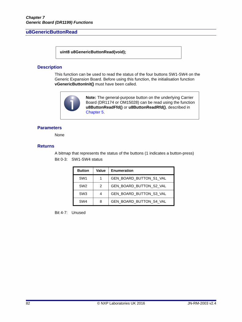
u8GenericButtonRead
Description
This function can be used to read the status of the four buttons SW1-SW4 on the Generic Expansion Board. Before using this function, the initialisation function vGenericButtonInit() must have been called.
Parameters
None
Returns
A bitmap that represents the status of the buttons (1 indicates a button-press)
Bit 0-3: SW1-SW4 status
Bit 4-7: Unused
uint8 u8GenericButtonRead(void);
Note: The general-purpose button on the underlying Carrier Board (DR1174 or OM15028) can be read using the function u8ButtonReadFfd() or u8ButtonReadRfd(), described in Chapter 5.
Button Value Enumeration
SW1 1 GEN_BOARD_BUTTON_S1_VAL
SW2 2 GEN_BOARD_BUTTON_S2_VAL
SW3 4 GEN_BOARD_BUTTON_S3_VAL
SW4 8 GEN_BOARD_BUTTON_S4_VAL
82 © NXP Laboratories UK 2016 JN-RM-2003 v2.4
LPRF Board APIReference Manual
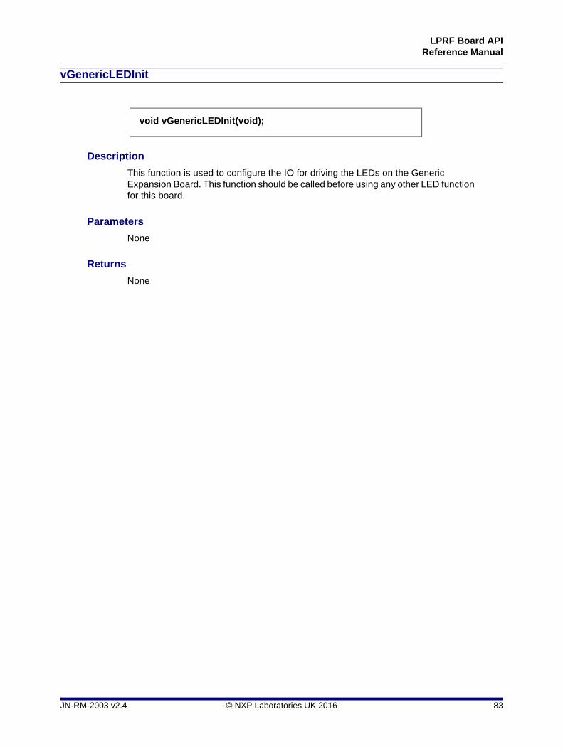
vGenericLEDInit
Description
This function is used to configure the IO for driving the LEDs on the Generic Expansion Board. This function should be called before using any other LED function for this board.
Parameters
None
Returns
None
void vGenericLEDInit(void);
JN-RM-2003 v2.4 © NXP Laboratories UK 2016 83
Chapter 7Generic Board (DR1199) Functions
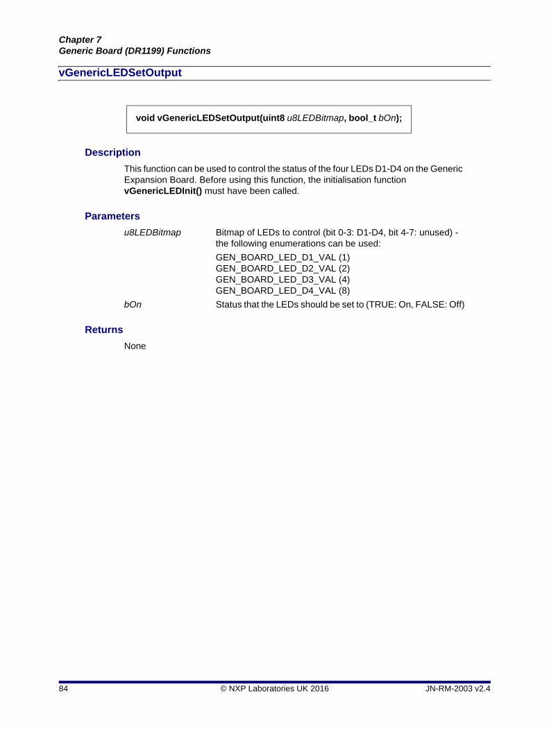
vGenericLEDSetOutput
Description
This function can be used to control the status of the four LEDs D1-D4 on the Generic Expansion Board. Before using this function, the initialisation function vGenericLEDInit() must have been called.
Parameters
u8LEDBitmap Bitmap of LEDs to control (bit 0-3: D1-D4, bit 4-7: unused) - the following enumerations can be used:
GEN_BOARD_LED_D1_VAL (1)GEN_BOARD_LED_D2_VAL (2)GEN_BOARD_LED_D3_VAL (4)GEN_BOARD_LED_D4_VAL (8)
bOn Status that the LEDs should be set to (TRUE: On, FALSE: Off)
Returns
None
void vGenericLEDSetOutput(uint8 u8LEDBitmap, bool_t bOn);
84 © NXP Laboratories UK 2016 JN-RM-2003 v2.4
LPRF Board APIReference Manual
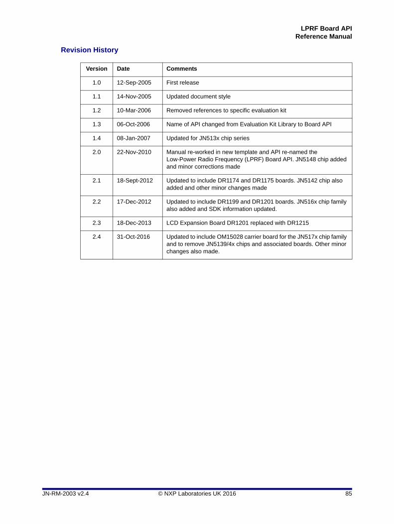
Revision History
Version Date Comments
1.0 12-Sep-2005 First release
1.1 14-Nov-2005 Updated document style
1.2 10-Mar-2006 Removed references to specific evaluation kit
1.3 06-Oct-2006 Name of API changed from Evaluation Kit Library to Board API
1.4 08-Jan-2007 Updated for JN513x chip series
2.0 22-Nov-2010 Manual re-worked in new template and API re-named the Low-Power Radio Frequency (LPRF) Board API. JN5148 chip added and minor corrections made
2.1 18-Sept-2012 Updated to include DR1174 and DR1175 boards. JN5142 chip also added and other minor changes made
2.2 17-Dec-2012 Updated to include DR1199 and DR1201 boards. JN516x chip family also added and SDK information updated.
2.3 18-Dec-2013 LCD Expansion Board DR1201 replaced with DR1215
2.4 31-Oct-2016 Updated to include OM15028 carrier board for the JN517x chip family and to remove JN5139/4x chips and associated boards. Other minor changes also made.
JN-RM-2003 v2.4 © NXP Laboratories UK 2016 85
LPRF Board APIReference Manual
Important Notice
Limited warranty and liability - Information in this document is believed to be accurate and reliable. However, NXP Semiconductors does not give any representations or warranties, expressed or implied, as to the accuracy or completeness of such information and shall have no liability for the consequences of use of such information. NXP Semiconductors takes no responsibility for the content in this document if provided by an information source outside of NXP Semiconductors.
In no event shall NXP Semiconductors be liable for any indirect, incidental, punitive, special or consequential damages (including - without limitation - lost profits, lost savings, business interruption, costs related to the removal or replacement of any products or rework charges) whether or not such damages are based on tort (including negligence), warranty, breach of contract or any other legal theory.
Notwithstanding any damages that customer might incur for any reason whatsoever, NXP Semiconductors' aggregate and cumulative liability towards customer for the products described herein shall be limited in accordance with the Terms and conditions of commercial sale of NXP Semiconductors.
Right to make changes - NXP Semiconductors reserves the right to make changes to information published in this document, including without limitation specifications and product descriptions, at any time and without notice. This document supersedes and replaces all information supplied prior to the publication hereof.
Suitability for use - NXP Semiconductors products are not designed, authorized or warranted to be suitable for use in life support, life-critical or safety-critical systems or equipment, nor in applications where failure or malfunction of an NXP Semiconductors product can reasonably be expected to result in personal injury, death or severe property or environmental damage. NXP Semiconductors and its suppliers accept no liability for inclusion and/or use of NXP Semiconductors products in such equipment or applications and therefore such inclusion and/or use is at the customer's own risk.
Applications - Applications that are described herein for any of these products are for illustrative purposes only. NXP Semiconductors makes no representation or warranty that such applications will be suitable for the specified use without further testing or modification.
Customers are responsible for the design and operation of their applications and products using NXP Semiconductors products, and NXP Semiconductors accepts no liability for any assistance with applications or customer product design. It is customer's sole responsibility to determine whether the NXP Semiconductors product is suitable and fit for the customer's applications and products planned, as well as for the planned application and use of customer's third party customer(s). Customers should provide appropriate design and operating safeguards to minimize the risks associated with their applications and products.
NXP Semiconductors does not accept any liability related to any default, damage, costs or problem which is based on any weakness or default in the customer's applications or products, or the application or use by customer's third party customer(s). Customer is responsible for doing all necessary testing for the customer's applications and products using NXP Semiconductors products in order to avoid a default of the applications and the products or of the application or use by customer's third party customer(s). NXP does not accept any liability in this respect.
Export control - This document as well as the item(s) described herein may be subject to export control regulations. Export might require a prior authorization from competent authorities.
NXP Semiconductors
For online support resources and contact details of your local NXP office or distributor, refer to:
www.nxp.com
86 © NXP Laboratories UK 2016 JN-RM-2003 v2.4