Embed Size (px)
Citation preview
Rev 409-06-2016 Page 1
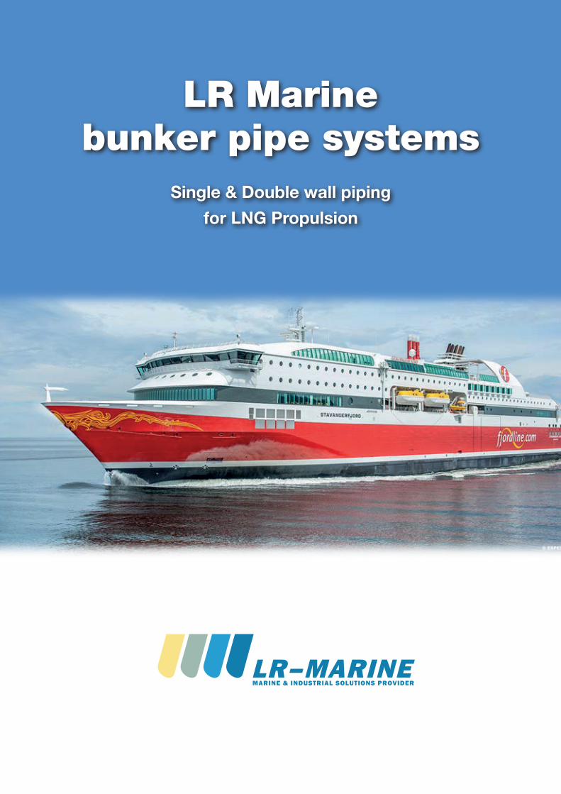
LR Marine bunker pipe systems Single & Double wall piping for LNG Propulsion
LR Marine bunker pipe systems
Single & Double wall piping for LNG Propulsion

2 2
Rev 409-06-2016 Page 4
LR Marine was founded in 2008 in Frederikshavn in Northern Jutland, in Denmark. The 5founders of the company comprises a team of highly qualified and dedicated profession-als offering a unique combination of technical insight, know how, project managementskills and years of experience within the field of marine and off shore operations.
LR Marine was established primarily to assume the sales responsibility for all LOGSTORMarine systems in Europe, and since January 1, 2012 the Geographical area has been ex-panded such that LR marine today is the worldwide exclusive distributor for LOGSTORMarine systems.
LR Marine operates worldwide via a network of specialized Marine agents and regularlyattends international exhibitions.
LR Marine is a total supplier of cost efficient, effective and sustainable solutions for ma-rine and off shore businesses.
LR Marine core business and primary activities are within the fields of:
- Pipe systems
- Pre-insulated pipe systems
- Machinery units / Skids
- Cryogenic Tank Insulation
- Service and installation
Since January 1, 2015 LR Marine has had the rights to the manufacturing know-how of the pre-insulated Marine piping systems and has acquired its own manufacturing facili-ties as well as using other sub-suppliers to produce the pre-insulated pipes per LR Marinespecifications. Type approvals from classification companies are also the property of LRMarine.
Since April 1, 2015 LR Marine has taken over the manufacturing facility in Wuxi, Shanghaiprovince China. This facility is primarily serving the vast new build market on the shipyards in China but can also serve the retro-fit market in the rest of the world.
LR Marine also operates mobile production units for the execution of large orders in re-mote places and where savings in logistics justifies it.
LR Marine remains to have its head quarter in Aalborg Denmark and operates the variousfacilities/sites from here
Introduction
Rev 409-06-2016 Page 5
The global shipping industry is facing challenges as International Marine Organization (IMO) has put in place restrictions on emissions from ships that has come into force in 2015 in the Emission Control Areas and 2020 for the rest of the world new. This legislation will significantly limit sulfur emissions from ships. LNG is a potential solution for meeting these requirements - it has virtually no sulfur content, and its combustion produces low NOx compared to fuel oil and marine diesel oil. LNG is not only clean-burning, but may have economic advantages - on a calorific value basis even high Asian LNG prices are lower than global bunker fuel prices. As a result there have been recent developments to promote use of LNG as a bunker fuel.
Using LNG as fuel will require modifications to the ship. In some cases it is possible to modify the fuel system using the same engine so the modifications are on the fuel tank system and fuel delivery system.
The LR MARINE Pre Insulated pipe system has successfully been delivered for Cryogenic pipe Insulation on 50+ LNG vessels so using the same system for LNG propulsion was obvious.
The primary benefit of LR Marine pre-insulated piping systems compared to conventional Cryogenic pipe insulation is that the system is a 100% waterproof bonded system, with no carrier pipe movements within the insulation system and total elimination of water ingress and mechanical wear. Due to the “Sandwich” construction, the complexity and the number of pipe supports can be significantly reduced and the supports are placed directly on the insulation jacket. Approximately 90% of the insulation is done in the LR MARINE factory reducing onsite work to only very few joints.
During the last few years, LR marine has been very active on many projects, which is currently under investigation here in Scandinavia either as new builds or as conversion from Marine Diesel Oil to Natural Gas propulsion. For this application we have several products.
LR Marine has been working with different Engine suppliers and the number of different piping systems required for any given project depends very much on individual project specific location of LNG storage tanks and pipe routing to the Engines.
LNG as fuel for ShipsLNG as fuel for Ships
32
Rev 409-06-2016 Page 4
LR Marine was founded in 2008 in Frederikshavn in Northern Jutland, in Denmark. The 5founders of the company comprises a team of highly qualified and dedicated profession-als offering a unique combination of technical insight, know how, project managementskills and years of experience within the field of marine and off shore operations.
LR Marine was established primarily to assume the sales responsibility for all LOGSTORMarine systems in Europe, and since January 1, 2012 the Geographical area has been ex-panded such that LR marine today is the worldwide exclusive distributor for LOGSTORMarine systems.
LR Marine operates worldwide via a network of specialized Marine agents and regularlyattends international exhibitions.
LR Marine is a total supplier of cost efficient, effective and sustainable solutions for ma-rine and off shore businesses.
LR Marine core business and primary activities are within the fields of:
- Pipe systems
- Pre-insulated pipe systems
- Machinery units / Skids
- Cryogenic Tank Insulation
- Service and installation
Since January 1, 2015 LR Marine has had the rights to the manufacturing know-how of the pre-insulated Marine piping systems and has acquired its own manufacturing facili-ties as well as using other sub-suppliers to produce the pre-insulated pipes per LR Marinespecifications. Type approvals from classification companies are also the property of LRMarine.
Since April 1, 2015 LR Marine has taken over the manufacturing facility in Wuxi, Shanghaiprovince China. This facility is primarily serving the vast new build market on the shipyards in China but can also serve the retro-fit market in the rest of the world.
LR Marine also operates mobile production units for the execution of large orders in re-mote places and where savings in logistics justifies it.
LR Marine remains to have its head quarter in Aalborg Denmark and operates the variousfacilities/sites from here
Introduction
Rev 409-06-2016 Page 5
The global shipping industry is facing challenges as International Marine Organization (IMO) has put in place restrictions on emissions from ships that has come into force in 2015 in the Emission Control Areas and 2020 for the rest of the world new. This legislation will significantly limit sulfur emissions from ships. LNG is a potential solution for meeting these requirements - it has virtually no sulfur content, and its combustion produces low NOx compared to fuel oil and marine diesel oil. LNG is not only clean-burning, but may have economic advantages - on a calorific value basis even high Asian LNG prices are lower than global bunker fuel prices. As a result there have been recent developments to promote use of LNG as a bunker fuel.
Using LNG as fuel will require modifications to the ship. In some cases it is possible to modify the fuel system using the same engine so the modifications are on the fuel tank system and fuel delivery system.
The LR MARINE Pre Insulated pipe system has successfully been delivered for Cryogenic pipe Insulation on 50+ LNG vessels so using the same system for LNG propulsion was obvious.
The primary benefit of LR Marine pre-insulated piping systems compared to conventional Cryogenic pipe insulation is that the system is a 100% waterproof bonded system, with no carrier pipe movements within the insulation system and total elimination of water ingress and mechanical wear. Due to the “Sandwich” construction, the complexity and the number of pipe supports can be significantly reduced and the supports are placed directly on the insulation jacket. Approximately 90% of the insulation is done in the LR MARINE factory reducing onsite work to only very few joints.
During the last few years, LR marine has been very active on many projects, which is currently under investigation here in Scandinavia either as new builds or as conversion from Marine Diesel Oil to Natural Gas propulsion. For this application we have several products.
LR Marine has been working with different Engine suppliers and the number of different piping systems required for any given project depends very much on individual project specific location of LNG storage tanks and pipe routing to the Engines.
LNG as fuel for ShipsLNG as fuel for Ships
3 Rev 409-06-2016 Page 6
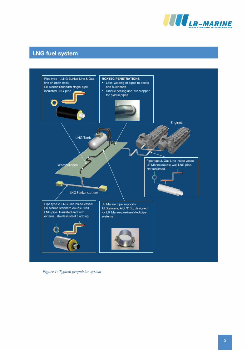
Figure 1: Typical propulsion system
LNG fuel systemLNG fuel system
LR MARINE has supplied Pre-Insulated Pipe systems to the most sophisticated LNG Carriers and
realized exceptional operational benefits
LR MARINE offers a Bunker pipe solution for every application
LNG Tank
Weatherdeck
LNG Bunker stations
Engines
Pipe type 2. LNG Line inside vesselLR Marine standard double wall LNG pipe Insulated. and with external stainless steel cladding
Pipe type 1. LNG Bunker Line & Gas line on open deckLR Marine Standard single pipeinsulated LNG pipe.
ROXTEC PENETRATIONS• Less welding of pipes to decks
and bulkheads• Unique sealing and fire stopper
for plastic pipes.
Pipe type 3. Gas Line inside vesselLR Marine double wall LNG pipe. Not Insulated.
LR Marine pipe supportsAll Stainless, AISI 316L, designed
for LR Marine pre- insulated pipe systems
LR-MARINE_12s_FOLDER_A4_30.10.15.indd 11 10/11/15 14.18
4 4
Rev 409-06-2016 Page 7
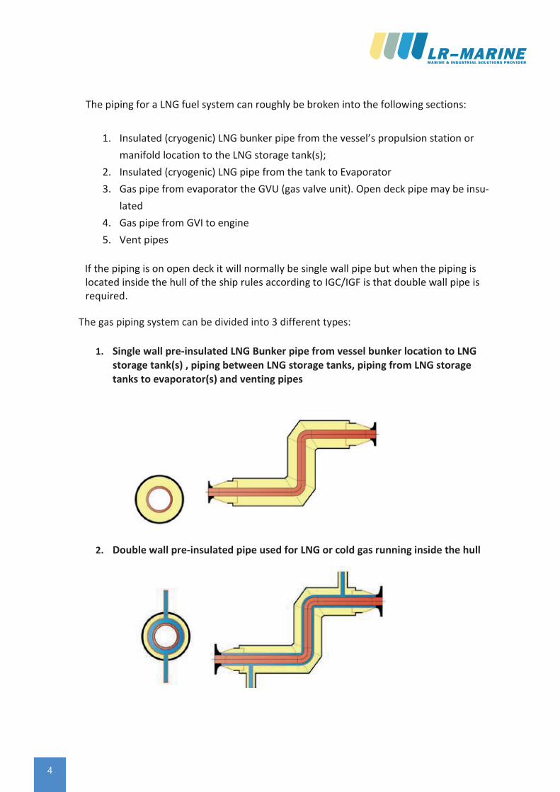
The piping for a LNG fuel system can roughly be broken into the following sections:
1. Insulated (cryogenic) LNG bunker pipe from the vessel’s propulsion station ormanifold location to the LNG storage tank(s);
2. Insulated (cryogenic) LNG pipe from the tank to Evaporator3. Gas pipe from evaporator the GVU (gas valve unit). Open deck pipe may be insu-
lated4. Gas pipe from GVI to engine5. Vent pipes
If the piping is on open deck it will normally be single wall pipe but when the piping is located inside the hull of the ship rules according to IGC/IGF is that double wall pipe is required.
Rev 409-06-2016 Page 6
Figure 1: Typical propulsion system
LNG fuel system
The gas piping system can be divided into 3 different types:
1. Single wall pre-insulated LNG Bunker pipe from vessel bunker location to LNGstorage tank(s) , piping between LNG storage tanks, piping from LNG storagetanks to evaporator(s) and venting pipes
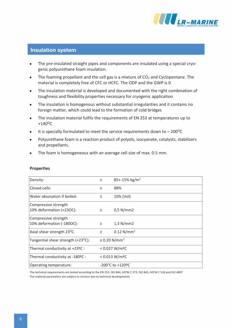
2. Double wall pre-insulated pipe used for LNG or cold gas running inside the hull

54
Rev 409-06-2016 Page 7
The piping for a LNG fuel system can roughly be broken into the following sections:
1. Insulated (cryogenic) LNG bunker pipe from the vessel’s propulsion station ormanifold location to the LNG storage tank(s);
2. Insulated (cryogenic) LNG pipe from the tank to Evaporator3. Gas pipe from evaporator the GVU (gas valve unit). Open deck pipe may be insu-
lated4. Gas pipe from GVI to engine5. Vent pipes
If the piping is on open deck it will normally be single wall pipe but when the piping is located inside the hull of the ship rules according to IGC/IGF is that double wall pipe is required.
Rev 409-06-2016 Page 6
Figure 1: Typical propulsion system
LNG fuel system
The gas piping system can be divided into 3 different types:
1. Single wall pre-insulated LNG Bunker pipe from vessel bunker location to LNGstorage tank(s) , piping between LNG storage tanks, piping from LNG storagetanks to evaporator(s) and venting pipes
2. Double wall pre-insulated pipe used for LNG or cold gas running inside the hull
5
Rev 409-06-2016 Page 8
The gas piping system can be divided into 3 different types:
1. Single wall pre-insulated LNG Bunker pipe from vessel bunker location to LNG storage tank(s) , piping between LNG storage tanks, piping from LNG storagetanks to evaporator(s) and venting pipes
2. Double wall pre-insulated pipe used for LNG or cold gas running inside the hull
Rev 409-06-2016 Page 9
3. Un-insulated double wall pipe used for ambient temperature gas running insidethe hull; typically the pipes going to the GVU and from GVU to engines
To qualify LR MARINE’s pre-insulated pipe systems for LNG applications, LR MA-RINE/LOGSTOR carried out an elaborate full scale test program at cryogenic tempera-tures.
The tests were made and documented by independent energy research institutes to ver-ify the properties needed for the cryogenic application:
- The mechanical test and thermal properties mentioned above were tested and verified over the full temperature range.
- The materials were cycled between ambient and cryogenic temperatures to verify the bond strength between PUR and carrier pipe.
- A full-scale test of a 4" and 20" pre-insulated pipe loop cycled between -196°C and +65°C supported by FEM analyses.
The test proved that even when cycled between cryogenic temperatures and ambient no cracks appeared. The test also demonstrated that the systems remains bonded (foam is bonded to the service pipe.
While attempting to make the test conditions as realistic as possible the real test has been the conditions under which pipes being in service since 2001 has been exposed to. LR Marine has supplied pipe insulation for LNG carriers since 2001 and we have no had one single cold spot appearing.
Qualification
6 6
Rev 409-06-2016 Page 11
• The pre-insulated straight pipes and components are insulated using a special cryo-genic polyurethane foam insulation.
• The foaming propellant and the cell gas is a mixture of CO2 and Cyclopentane. Thematerial is completely free of CFC or HCFC. The ODP and the GWP is 0
• The insulation material is developed and documented with the right combination oftoughness and flexibility properties necessary for cryogenic application
• The insulation is homogenous without substantial irregularities and it contains noforeign matter, which could lead to the formation of cold bridges
• The insulation material fulfils the requirements of EN 253 at temperatures up to+140OC
• It is specially formulated to meet the service requirements down to – 200OC
• Polyurethane foam is a reaction product of polyols, isocyanate, catalysts, stabilizersand propellants.
• The foam is homogeneous with an average cell size of max. 0.5 mm.
Properties
Density: ≥ 85+-15% kg/m3
Closed cells: ≥ 88%
Water absorption if boiled: ≤ 10% (Vol)
Compressive strength 10% deformation (+23OC): ≥ 0,5 N/mm2
Compressive strength 10% deformation (-180OC): ≥ 1,3 N/mm2
Axial shear strength 23OC ≥ 0.12 N/mm2
Tangential shear strength (+23OC): ≥ 0.20 N/mm2
Thermal conductivity at +23ºC : < 0.027 W/mºC
Thermal conductivity at -180ºC : < 0.013 W/mºC
Operating temperature: -200°C to +120ºC
The technical requirements are tested according to the EN 253, ISO 844, ASTM C 273, ISO 845, ASTM C 518 and ISO 4897 The material parameters are subject to revision due to technical developments.
Insulation system
Insulation system
76
Rev 409-06-2016 Page 11
• The pre-insulated straight pipes and components are insulated using a special cryo-genic polyurethane foam insulation.
• The foaming propellant and the cell gas is a mixture of CO2 and Cyclopentane. Thematerial is completely free of CFC or HCFC. The ODP and the GWP is 0
• The insulation material is developed and documented with the right combination oftoughness and flexibility properties necessary for cryogenic application
• The insulation is homogenous without substantial irregularities and it contains noforeign matter, which could lead to the formation of cold bridges
• The insulation material fulfils the requirements of EN 253 at temperatures up to+140OC
• It is specially formulated to meet the service requirements down to – 200OC
• Polyurethane foam is a reaction product of polyols, isocyanate, catalysts, stabilizersand propellants.
• The foam is homogeneous with an average cell size of max. 0.5 mm.
Properties
Density: ≥ 85+-15% kg/m3
Closed cells: ≥ 88%
Water absorption if boiled: ≤ 10% (Vol)
Compressive strength 10% deformation (+23OC): ≥ 0,5 N/mm2
Compressive strength 10% deformation (-180OC): ≥ 1,3 N/mm2
Axial shear strength 23OC ≥ 0.12 N/mm2
Tangential shear strength (+23OC): ≥ 0.20 N/mm2
Thermal conductivity at +23ºC : < 0.027 W/mºC
Thermal conductivity at -180ºC : < 0.013 W/mºC
Operating temperature: -200°C to +120ºC
The technical requirements are tested according to the EN 253, ISO 844, ASTM C 273, ISO 845, ASTM C 518 and ISO 4897 The material parameters are subject to revision due to technical developments.
Insulation system
Insulation system
7
Rev 409-06-2016 Page 12
Casing material (HDPE)
The casing on the PRE-INSULATED PIPE system is extruded from black coloured High Den-sity Polyethylene (HDPE). The HDPE materials used are chosen for their toughness and outstanding resistance against UV degradation, slow crack growth and rapid crack propa-gation. They are therefore well suited for service under as well tropical as arctic condition in a period exceeding 30 years.
Every pipe or fitting is delivered with a free media pipe end of 150-220mm. for welding
Casings in outer diameter up to 1400mm. are available
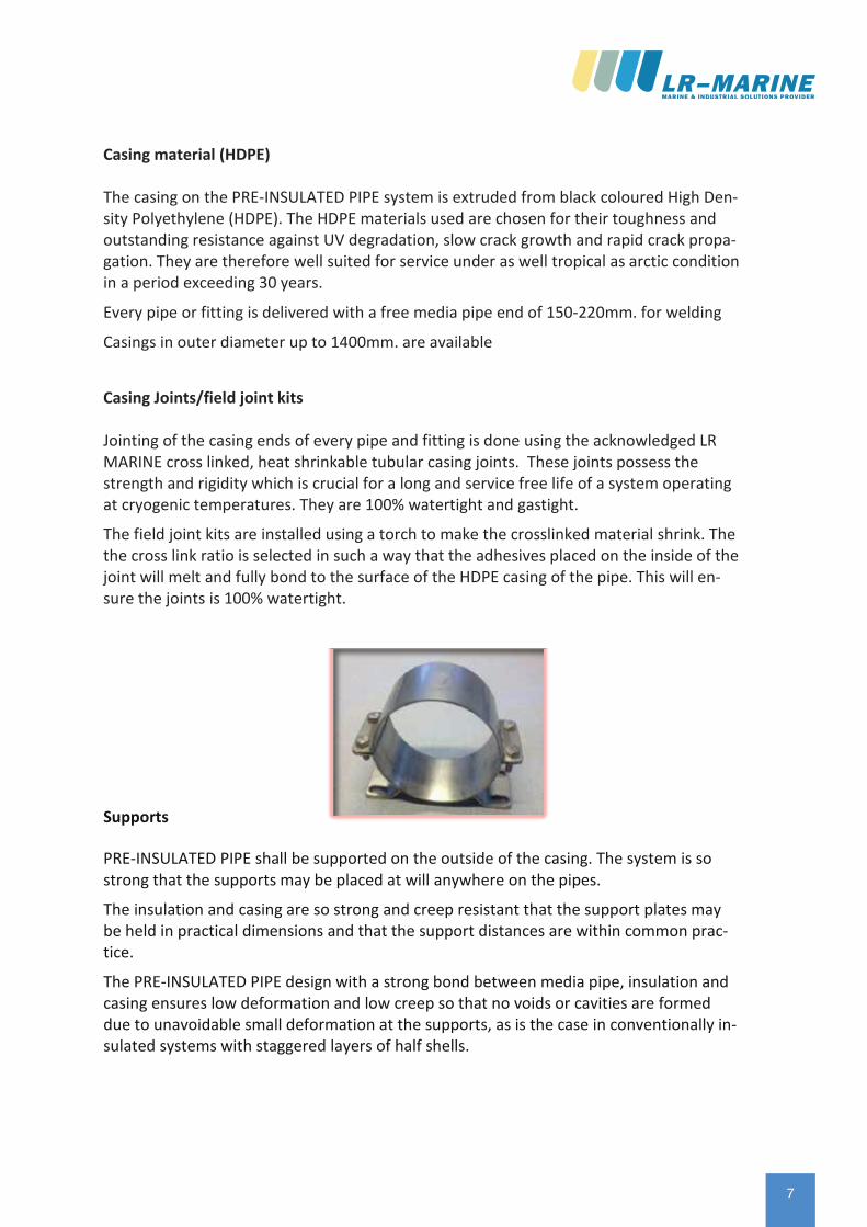
Casing Joints/field joint kits
Jointing of the casing ends of every pipe and fitting is done using the acknowledged LR MARINE cross linked, heat shrinkable tubular casing joints. These joints possess the strength and rigidity which is crucial for a long and service free life of a system operating at cryogenic temperatures. They are 100% watertight and gastight.
The field joint kits are installed using a torch to make the crosslinked material shrink. The the cross link ratio is selected in such a way that the adhesives placed on the inside of the joint will melt and fully bond to the surface of the HDPE casing of the pipe. This will en-sure the joints is 100% watertight.
Supports
PRE-INSULATED PIPE shall be supported on the outside of the casing. The system is so strong that the supports may be placed at will anywhere on the pipes.
The insulation and casing are so strong and creep resistant that the support plates may be held in practical dimensions and that the support distances are within common prac-tice.
The PRE-INSULATED PIPE design with a strong bond between media pipe, insulation and casing ensures low deformation and low creep so that no voids or cavities are formed due to unavoidable small deformation at the supports, as is the case in conventionally in-sulated systems with staggered layers of half shells.
8 8
Rev 409-06-2016 Page 13
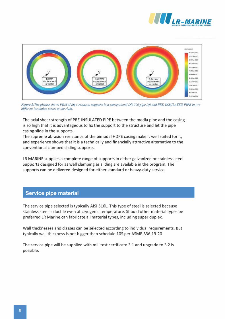
Figure 2:The picture shows FEM of the stresses at supports in a conventional DN 500 pipe left and PRE-INSULATED PIPE in two different insulation series at the right.
The axial shear strength of PRE-INSULATED PIPE between the media pipe and the casing is so high that it is advantageous to fix the support to the structure and let the pipe casing slide in the supports. The supreme abrasion resistance of the bimodal HDPE casing make it well suited for it, and experience shows that it is a technically and financially attractive alternative to the conventional clamped sliding supports.
LR MARINE supplies a complete range of supports in either galvanized or stainless steel. Supports designed for as well clamping as sliding are available in the program. The supports can be delivered designed for either standard or heavy-duty service.
The service pipe selected is typically AISI 316L. This type of steel is selected because stainless steel is ductile even at cryogenic temperature. Should other material types be preferred LR Marine can fabricate all material types, including super duplex.
Wall thicknesses and classes can be selected according to individual requirements. But typically wall thickness is not bigger than schedule 10S per ASME B36.19-20
The service pipe will be supplied with mill test certificate 3.1 and upgrade to 3.2 is possible.
Service pipe material
98
Rev 409-06-2016 Page 13
Figure 2:The picture shows FEM of the stresses at supports in a conventional DN 500 pipe left and PRE-INSULATED PIPE in two different insulation series at the right.
The axial shear strength of PRE-INSULATED PIPE between the media pipe and the casing is so high that it is advantageous to fix the support to the structure and let the pipe casing slide in the supports. The supreme abrasion resistance of the bimodal HDPE casing make it well suited for it, and experience shows that it is a technically and financially attractive alternative to the conventional clamped sliding supports.
LR MARINE supplies a complete range of supports in either galvanized or stainless steel. Supports designed for as well clamping as sliding are available in the program. The supports can be delivered designed for either standard or heavy-duty service.
The service pipe selected is typically AISI 316L. This type of steel is selected because stainless steel is ductile even at cryogenic temperature. Should other material types be preferred LR Marine can fabricate all material types, including super duplex.
Wall thicknesses and classes can be selected according to individual requirements. But typically wall thickness is not bigger than schedule 10S per ASME B36.19-20
The service pipe will be supplied with mill test certificate 3.1 and upgrade to 3.2 is possible.
Service pipe material
9
Rev 409-06-2016 Page 14
The service pipe selected is typically AISI 316L. This type of steel is selected becausestainless steel is ductile even at cryogenic temperature. Should other material types bepreferred LR Marine can fabricate all material types, including super duplex.
Wall thicknesses and classes can be selected according to individual requirements. But typically wall thickness is not bigger than schedule 10S per ASME B36.19-20
The service pipe will be supplied with mill test certificate 3.1 and upgrade to 3.2 ispossible.
Service pipe material
Rev 409-06-2016 Page 15
LR MARINE pipe insulation systems has standard type approval by DNV/GL, Lloyds and ABS for all applications on open deck and in cargo holds and we have recently conducted a series of test to get system approval for this specific system applied for LNG Bunker pipelines inside vessels from Bunker station to LNG Storage tanks. The LR Marine Bunker Line system has been applied and approved for the NB 87 M/S Stavangerfjord built at Bergen Group Fosen shipyard in Norway. The vessel started operation on July 14, 2013.
Responsibility of class Approval of individual propulsion systems lies with the shipyard but LR Marine shall obviously assist to gain necessary documentation to obtain approvals.
To obtain approval the piping system shall be well documented and the required documentation to get class approval can be obtained from LR Marine. The requirements may differ from one class society to another so you should contact LR Marine to assist with this well in advance.
Type approvalType approval
• Service pipe wall thicknesso The wall thickness is calculated through code requirements and depends
on type of material and if the pipe is welded or seamless. This is animportant point to note because seamless stainless steel pipes are bothexpensive and difficult to source so this must be agreed withclassification company at early stage.
• Service pipe routing in confined spaceo When routing the pipe through confines space/hull the room must be
vented with 30 air changes per hour or the pipe to be enclosed in asecondary conduit with air in between vented or pressurized using inertgas.
• Service pipe joint methodo Only but welding is allowed. Flanges can be used where butt welding is
not practical possible of units must be removed easily for maintenance• Pressure rating of conduit piping
o Conduit carrying the service pipe shall have same pressure rating as theservice pipe.
• Stress analysiso For pipes with design temperature lower than -110°C the pipe system
must be analyzed using computerized stress analysis method. Practicallythat means most piping systems must be analyzed since there is a risk ofhaving liquid gas (LNG) flowing through the pipe.
Class requirements
• Ventilationo Double wall pipes must be vented with 30 air changes per hour,
alternatively the annulus can be pressurized using inert gas and equippedwith a pressure sensor detection loss of pressure or increase of pressure.

10 10
Rev 409-06-2016 Page 16
Regardless what classification organization is used the requirements will be moreor less identical since the requirements derives from IMO’s international gascodes (IGC & IGF).
This catalogue is not capable of mentioning all the requirements from IMO or class society but here are some important point listed:
• Service pipe materialo Stainless steel is not directly mentioned but since this is the most
commonly available material it is usually used for this type of pipes• Service pipe qualification
o The service pipe material (and conduit) requirements are clearly definedand the test requirements are also clearly define. The test requirementsare too comprehensive to mention here but they will consist of Impact test Tensile strength
o The testing may not be carried out at manufacturer’s laboratory so thetime needed to get the material qualified should be considered. Some of the tests must be carried out at temperature lower than ambient and notall test facilities are having the equipment to do so.
• Service pipe wall thicknesso The wall thickness is calculated through code requirements and depends
on type of material and if the pipe is welded or seamless. This is animportant point to note because seamless stainless steel pipes are bothexpensive and difficult to source so this must be agreed withclassification company at early stage.
• Service pipe routing in confined spaceo When routing the pipe through confines space/hull the room must be
vented with 30 air changes per hour or the pipe to be enclosed in asecondary conduit with air in between vented or pressurized using inertgas.
• Service pipe joint methodo Only but welding is allowed. Flanges can be used where butt welding is
not practical possible of units must be removed easily for maintenance• Pressure rating of conduit piping
o Conduit carrying the service pipe shall have same pressure rating as theservice pipe.
• Stress analysis
Class requirements
Rev 409-06-2016 Page 17
• Protection against mechanical damageo Gas pipes led through ro-ro spaces, special category spaces and on open
decks shall be protected against mechanical damage. If the pipe is singlewall, which is typical on open deck the insulation LR Marine provides willprotect the pipe against both mechanical damage as well from corrosiondue to seawater exposure.
Often many points are agreed to on a project to project basis so the above is only part of the requirements.
Stainless steel has a much higher coefficient of expansion or contraction when compared to carbon steel. When cooled down to cryogenic temperature of -165°C at which the LNG is typically stored the pipe will contract approximately 3 mm per meter of pipe, so if the total pipe length is 100 meter the total contraction will be 300 mm. When deciding the pipe routing this has to be taken into consideration to ensure the pipe is not over stressed.
The insulation provided by LR Marine is bonded the surface of the service pipe. So the insulation will follow the movements of the pipe even at cryogenic temperature. Combine with a high compressive strength of the foam this allows us to place the pipe supports directly on the jacket avoiding the typical high density inserts usually used for cryogenic pipe supports.
The double pipe system is non bonded allowing the service pipe free movement. To ensure the service pipe remains centered LR Marine has designed a special spacing system utilizing custom built springs. This will allow the pipe to move both in straight and
in elbows.
Pipe movement
Regardless what classification organization is used the requirements will be more or less identical since the requirements derives from IMO’s international gas codes (IGC & IGF).
This catalogue is not capable of mentioning all the requirements from IMO or class society but here are some important point listed:
• Service pipe materialo Stainless steel is not directly mentioned but since this is the most
commonly available material it is usually used for this type of pipes• Service pipe qualification
o The service pipe material (and conduit) requirements are clearly definedand the test requirements are also clearly define. The test requirementsare too comprehensive to mention here but they will consist of Impact test Tensile strength
o The testing may not be carried out at manufacturer’s laboratory so thetime needed to get the material qualified should be considered. Some ofthe tests must be carried out at temperature lower than ambient and notall test facilities are having the equipment to do so.
Class requirements

1110
Rev 409-06-2016 Page 16
Regardless what classification organization is used the requirements will be moreor less identical since the requirements derives from IMO’s international gascodes (IGC & IGF).
This catalogue is not capable of mentioning all the requirements from IMO or class society but here are some important point listed:
• Service pipe materialo Stainless steel is not directly mentioned but since this is the most
commonly available material it is usually used for this type of pipes• Service pipe qualification
o The service pipe material (and conduit) requirements are clearly definedand the test requirements are also clearly define. The test requirementsare too comprehensive to mention here but they will consist of Impact test Tensile strength
o The testing may not be carried out at manufacturer’s laboratory so thetime needed to get the material qualified should be considered. Some of the tests must be carried out at temperature lower than ambient and notall test facilities are having the equipment to do so.
• Service pipe wall thicknesso The wall thickness is calculated through code requirements and depends
on type of material and if the pipe is welded or seamless. This is animportant point to note because seamless stainless steel pipes are bothexpensive and difficult to source so this must be agreed withclassification company at early stage.
• Service pipe routing in confined spaceo When routing the pipe through confines space/hull the room must be
vented with 30 air changes per hour or the pipe to be enclosed in asecondary conduit with air in between vented or pressurized using inertgas.
• Service pipe joint methodo Only but welding is allowed. Flanges can be used where butt welding is
not practical possible of units must be removed easily for maintenance• Pressure rating of conduit piping
o Conduit carrying the service pipe shall have same pressure rating as theservice pipe.
• Stress analysis
Class requirements
Rev 409-06-2016 Page 17
• Protection against mechanical damageo Gas pipes led through ro-ro spaces, special category spaces and on open
decks shall be protected against mechanical damage. If the pipe is singlewall, which is typical on open deck the insulation LR Marine provides willprotect the pipe against both mechanical damage as well from corrosiondue to seawater exposure.
Often many points are agreed to on a project to project basis so the above is only part of the requirements.
Stainless steel has a much higher coefficient of expansion or contraction when compared to carbon steel. When cooled down to cryogenic temperature of -165°C at which the LNG is typically stored the pipe will contract approximately 3 mm per meter of pipe, so if the total pipe length is 100 meter the total contraction will be 300 mm. When deciding the pipe routing this has to be taken into consideration to ensure the pipe is not over stressed.
The insulation provided by LR Marine is bonded the surface of the service pipe. So the insulation will follow the movements of the pipe even at cryogenic temperature. Combine with a high compressive strength of the foam this allows us to place the pipe supports directly on the jacket avoiding the typical high density inserts usually used for cryogenic pipe supports.
The double pipe system is non bonded allowing the service pipe free movement. To ensure the service pipe remains centered LR Marine has designed a special spacing system utilizing custom built springs. This will allow the pipe to move both in straight and
in elbows.
Pipe movement
Regardless what classification organization is used the requirements will be more or less identical since the requirements derives from IMO’s international gas codes (IGC & IGF).
This catalogue is not capable of mentioning all the requirements from IMO or class society but here are some important point listed:
• Service pipe materialo Stainless steel is not directly mentioned but since this is the most
commonly available material it is usually used for this type of pipes• Service pipe qualification
o The service pipe material (and conduit) requirements are clearly definedand the test requirements are also clearly define. The test requirementsare too comprehensive to mention here but they will consist of Impact test Tensile strength
o The testing may not be carried out at manufacturer’s laboratory so thetime needed to get the material qualified should be considered. Some ofthe tests must be carried out at temperature lower than ambient and notall test facilities are having the equipment to do so.
Class requirements
11
Rev 409-06-2016 Page 18
Stainless steel has a much higher coefficient of expansion or contraction when compared to carbon steel. When cooled down to cryogenic temperature of -165°C at which the LNGis typically stored the pipe will contract approximately 3 mm per meter of pipe, so if thetotal pipe length is 100 meter the total contraction will be 300 mm. When deciding thepipe routing this has to be taken into consideration to ensure the pipe is not overstressed.
The insulation provided by LR Marine is bonded the surface of the service pipe. So theinsulation will follow the movements of the pipe even at cryogenic temperature.Combine with a high compressive strength of the foam this allows us to place the pipesupports directly on the jacket avoiding the typical high density inserts usually used forcryogenic pipe supports.
The double pipe system is non bonded allowing the service pipe free movement. Toensure the service pipe remains centered LR Marine has designed a special spacingsystem utilizing custom built springs. This will allow the pipe to move both in straight and in elbows.
Pipe movement
Rev 409-06-2016 Page 19
Once the routing of the pipe system is frozen LR Marine will conduct a stress analysis. Depending on class requirements typically only pipes with an operating temperature below -110°C requires a stress analysis.
Stress analysis is a finite element analysis breaking the pipe system into small elements and analyzing them one by one to determine the stresses and strains in the pipe as well as the pipe movements. To do so the system must be described in 3D and the external loads applied.
LR Marine is using Caesar II software to analyze the pipe system. The output is stress and strain in all defined nodes and the movement in the nodes. LR Marine will ensure that the stresses and strains are well within code requirements and we shall ensure the movements of the system are acceptable.
The first task to do is to made a 3D routing of the piping system
Figure 3: typical 3D pipe routing
Stress analysisStress analysis
1212
Rev 409-06-2016 Page 20
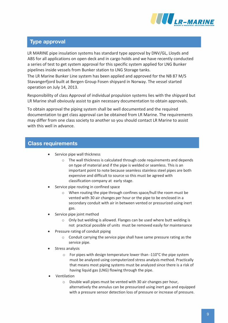
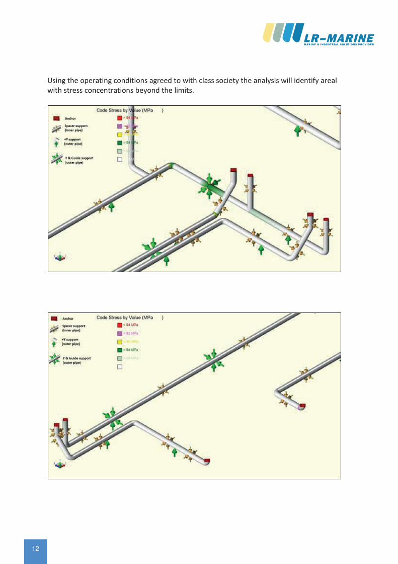
Using the operating conditions agreed to with class society the analysis will identify areal with stress concentrations beyond the limits.
1312
Rev 409-06-2016 Page 20
Using the operating conditions agreed to with class society the analysis will identify areal with stress concentrations beyond the limits.
13
Rev 409-06-2016 Page 20
Using the operating conditions agreed to with class society the analysis will identify arealwith stress concentrations beyond the limits.
Rev 409-06-2016 Page 21
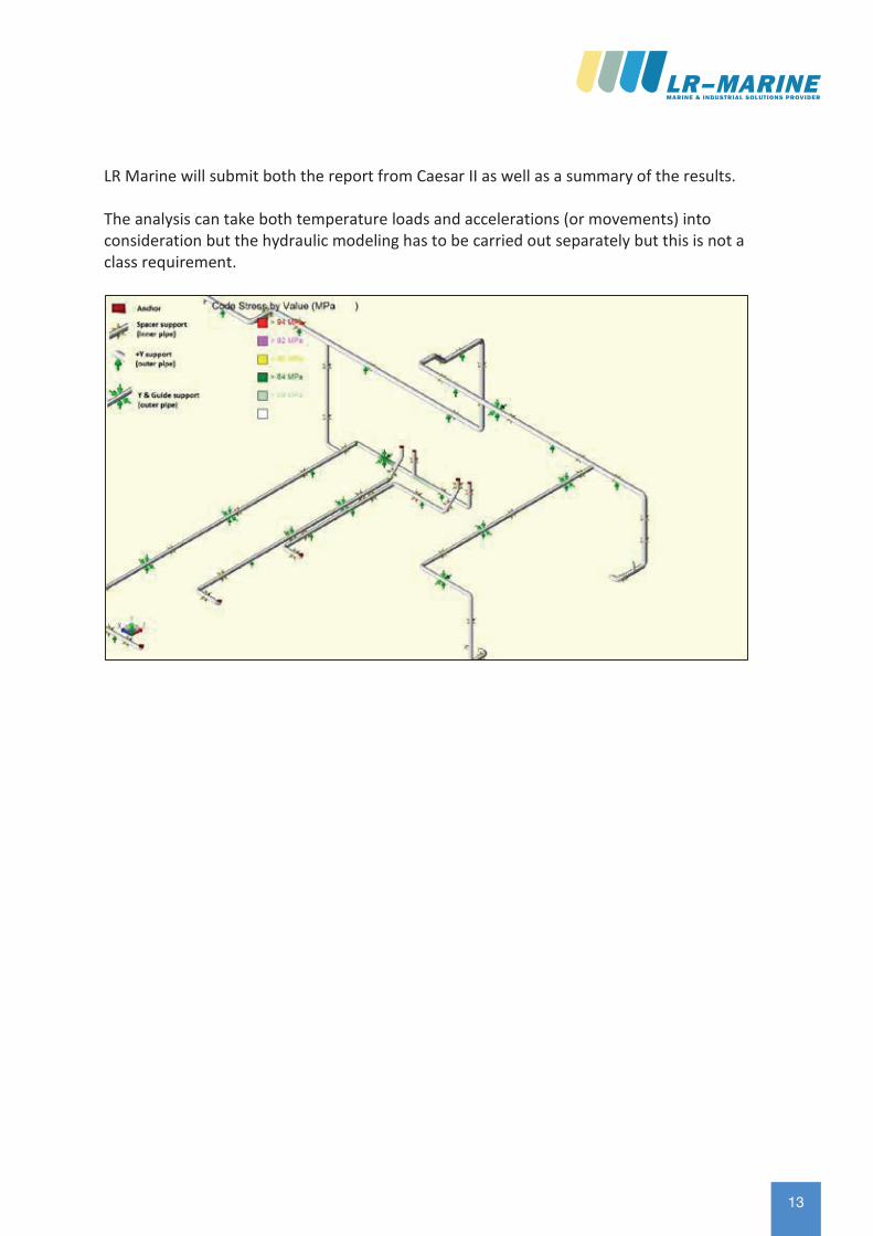
LR Marine will submit both the report from Caesar II as well as a summary of the results.
The analysis can take both temperature loads and accelerations (or movements) into consideration but the hydraulic modeling has to be carried out separately but this is not a class requirement.
1414
Rev 409-06-2016 Page 22
According to IMO regulations “Gas fuel piping should not pass through accommodation spaces, service spaces, or control stations. Gas fuel piping may pass through or extend into other spaces provided they fulfil one of the following
1. the gas fuel piping should be a double wall piping system with the gas fuel con-tained in the inner pipe. The space between the concentric pipes should be pres-surized with inert gas at a pressure greater than the gas fuel pressure. Suitablealarms should be provided to indicate a loss of inert gas pressure between thepipes; or
2. the gas fuel piping should be installed within a ventilated pipe or duct. The airspace between the gas fuel piping and inner wall of this pipe or duct should beequipped with mechanical exhaust ventilation having a capacity of at least 30 airchanges per hour.”
LR Marine can fabricate the pipe system according to the preference of the client how-ever the integration of alarm systems will not fall in our scope. The system can be deliv-ered with branches to allow venting using inert gas or a system that can be pressurized with an inert gas and fitted with pressure sensors detecting loss of pressure.
But if venting is selected it should be taken into consideration that if the service pipe is operated at cryogenic temperature any moisture introduced through the venting will condensate and turn into ice.
Venting optionsVenting options
The following section indicated the individual components in the piping system. However LR Marine does not supply the pipe system as “sticks and kits” but as a complete spool system. Using out vast experience we divide the system into spools to minimize the work at the shipyard and to reduce the risk of locking the pipe inappropriately. It is important that the pipe is allowed to move freely and the elbows allow this movement.
During installation LR Marine supervisor is overlooking the installation to ensure proper installation and that the components are placed in the right place.
Components description
1514
Rev 409-06-2016 Page 22
According to IMO regulations “Gas fuel piping should not pass through accommodation spaces, service spaces, or control stations. Gas fuel piping may pass through or extend into other spaces provided they fulfil one of the following
1. the gas fuel piping should be a double wall piping system with the gas fuel con-tained in the inner pipe. The space between the concentric pipes should be pres-surized with inert gas at a pressure greater than the gas fuel pressure. Suitablealarms should be provided to indicate a loss of inert gas pressure between thepipes; or
2. the gas fuel piping should be installed within a ventilated pipe or duct. The airspace between the gas fuel piping and inner wall of this pipe or duct should beequipped with mechanical exhaust ventilation having a capacity of at least 30 airchanges per hour.”
LR Marine can fabricate the pipe system according to the preference of the client how-ever the integration of alarm systems will not fall in our scope. The system can be deliv-ered with branches to allow venting using inert gas or a system that can be pressurized with an inert gas and fitted with pressure sensors detecting loss of pressure.
But if venting is selected it should be taken into consideration that if the service pipe is operated at cryogenic temperature any moisture introduced through the venting will condensate and turn into ice.
Venting optionsVenting options
The following section indicated the individual components in the piping system. However LR Marine does not supply the pipe system as “sticks and kits” but as a complete spool system. Using out vast experience we divide the system into spools to minimize the work at the shipyard and to reduce the risk of locking the pipe inappropriately. It is important that the pipe is allowed to move freely and the elbows allow this movement.
During installation LR Marine supervisor is overlooking the installation to ensure proper installation and that the components are placed in the right place.
Components description
15
Rev 409-06-2016 Page 24
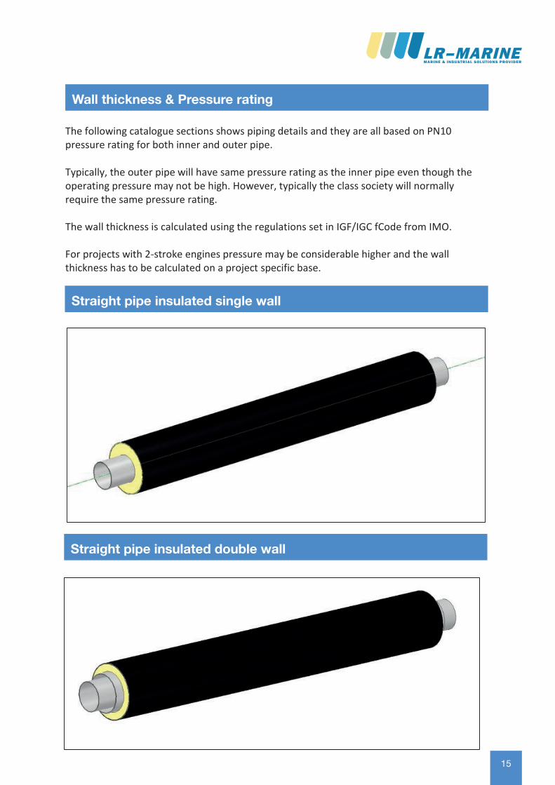
The following catalogue sections shows piping details and they are all based on PN10 pressure rating for both inner and outer pipe.
Typically, the outer pipe will have same pressure rating as the inner pipe even though the operating pressure may not be high. However, typically the class society will normally require the same pressure rating.
The wall thickness is calculated using the regulations set in IGF/IGC fCode from IMO.
For projects with 2-stroke engines pressure may be considerable higher and the wall thickness has to be calculated on a project specific base.
Wall thickness & Pressure ratingWall thickness & Pressure rating
Straight pipe insulated single wall
Straight pipe insulated double wall
16 16
Rev 409-06-2016 Page 26
Service pipe Conduit pipe HDPEjacket
U-value Weightpermeter
DN Inches OD [mm]
WT [mm]
DN Inches OD [mm]
WT [mm]
OD [mm]
[W/m2°C]
[kg]
15 ½ 21.3 2.0 40 1½ 48.3 2.0 160 0.286 6.1320 ¾ 26.9 2.0 50 2 60.3 2.0 160 0.323 6.9425 1 33.7 2.0 50 2 60.3 2.0 160 0.323 7.2832 1¼ 42.4 2.0 65 2½ 76,1 2.0 180 0.309 8.9140 1½ 48.3 2.0 65 2½ 76.1 2.0 180 0.309 9.2050 2 60.3 2.0 80 3 88.9 2.0 200 0.290 11.0565 2½ 76.1 2.0 100 4 114.3 2.0 225 0.294 13.9380 3 88.9 2.0 100 4 114.3 2.0 225 0.294 14.56100 4 114.3 2.0 125 5 139.7 2.0 250 0.298 17.98125 5 139.7 2.0 150 6 168.3 2.0 280 0.297 21.86150 6 168.3 2.0 200 8 219.1 2.0 355 0.245 29.72200 8 219.1 2.0 250 10 273.0 3.0 400 0.268 43.77250 10 273.0 3.0 300 12 323.9 3.0 450 0.275 59.86300 12 323.9 3.0 350 14 355.6 3.0 500 0.282 69.82
Pipes can be supplied in 6 meter lengths. Other lengths available upon request. Wall thickness for servicepipe may be project specific and selected to be thinner or thicker. The service pipe OD may also be supplied as metric.
Straight pipe insulated double wall
Rev 409-06-2016 Page 27
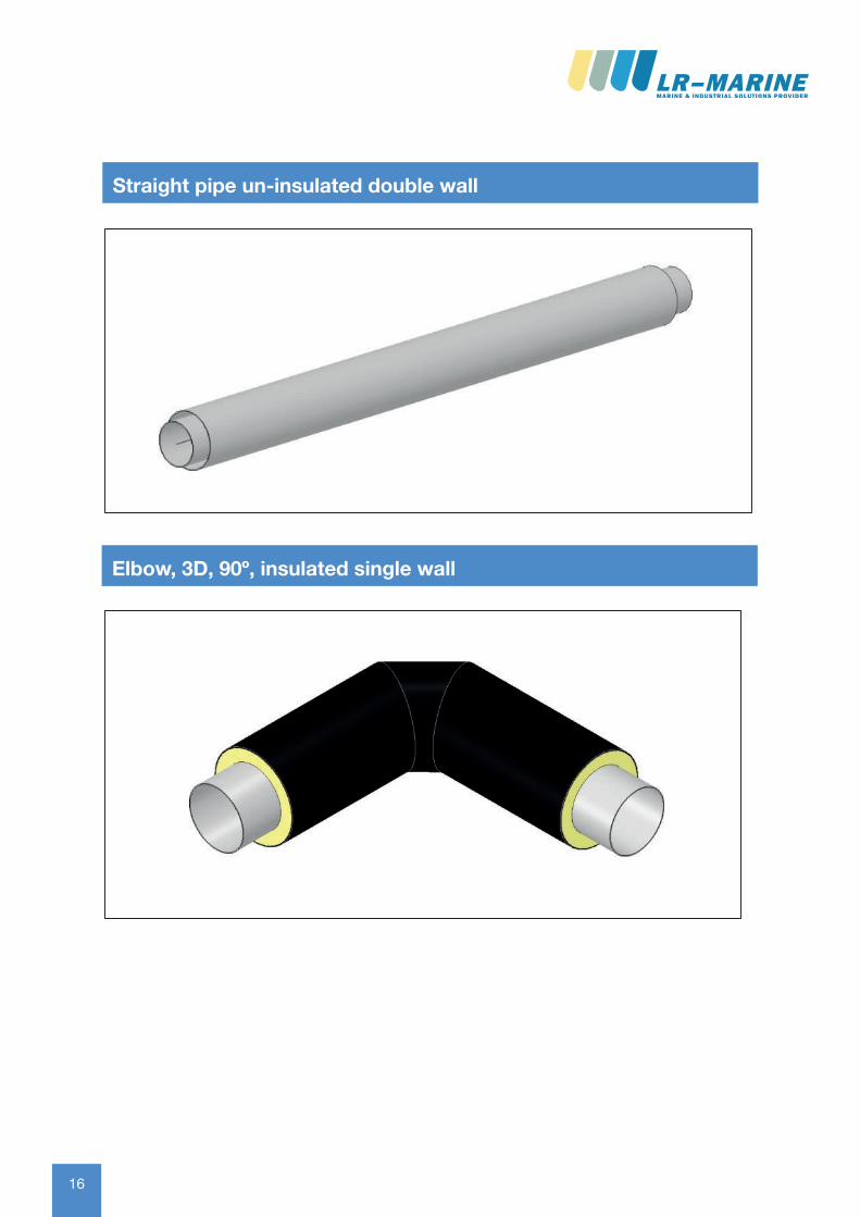
Straight pipe un-insulated double wallStraight pipe un-insulated double wall
Elbow, 3D, 90º, insulated single wall
1716
Rev 409-06-2016 Page 26
Service pipe Conduit pipe HDPEjacket
U-value Weightpermeter
DN Inches OD [mm]
WT [mm]
DN Inches OD [mm]
WT [mm]
OD [mm]
[W/m2°C]
[kg]
15 ½ 21.3 2.0 40 1½ 48.3 2.0 160 0.286 6.1320 ¾ 26.9 2.0 50 2 60.3 2.0 160 0.323 6.9425 1 33.7 2.0 50 2 60.3 2.0 160 0.323 7.2832 1¼ 42.4 2.0 65 2½ 76,1 2.0 180 0.309 8.9140 1½ 48.3 2.0 65 2½ 76.1 2.0 180 0.309 9.2050 2 60.3 2.0 80 3 88.9 2.0 200 0.290 11.0565 2½ 76.1 2.0 100 4 114.3 2.0 225 0.294 13.9380 3 88.9 2.0 100 4 114.3 2.0 225 0.294 14.56100 4 114.3 2.0 125 5 139.7 2.0 250 0.298 17.98125 5 139.7 2.0 150 6 168.3 2.0 280 0.297 21.86150 6 168.3 2.0 200 8 219.1 2.0 355 0.245 29.72200 8 219.1 2.0 250 10 273.0 3.0 400 0.268 43.77250 10 273.0 3.0 300 12 323.9 3.0 450 0.275 59.86300 12 323.9 3.0 350 14 355.6 3.0 500 0.282 69.82
Pipes can be supplied in 6 meter lengths. Other lengths available upon request. Wall thickness for servicepipe may be project specific and selected to be thinner or thicker. The service pipe OD may also be supplied as metric.
Straight pipe insulated double wall
Rev 409-06-2016 Page 27
Straight pipe un-insulated double wallStraight pipe un-insulated double wall
Elbow, 3D, 90º, insulated single wall
17
Rev 409-06-2016 Page 28
Service pipe HDPEjacket
U-value Weight per pcs.
DN Inches OD [mm] WT [mm] OD [mm] [W/m2°C] [kg]15 ½ 21.3 2.0 125 0.304 5.0520 ¾ 26.9 2.0 125 0.322 5.5925 1 33.7 2.0 125 0.347 6.2132 1¼ 42.4 2.0 140 0.328 7.7740 1½ 48.3 2.0 160 0.286 9.1550 2 60.3 2.0 160 0.323 10.1265 2½ 76.1 2.0 180 0.309 12.2580 3 88.9 2.0 200 0.290 14.37100 4 114.3 2.0 225 0.294 17.89125 5 139.7 2.0 250 0.298 21.50150 6 168.3 2.0 280 0.297 25.70200 8 219.1 2.0 355 0.245 35.29250 10 273.0 3.0 400 0.268 54.95300 12 323.9 3.0 450 0.275 70.21
Elbows have lengths of 1 by 1 meter. Other lengths available upon request. Wall thickness may be project specific and selected to be thinner or thicker. The pipe OD may also be supplied as metric.
Elbow, 3D, 90°, insulated single wall
Rev 409-06-2016 Page 29
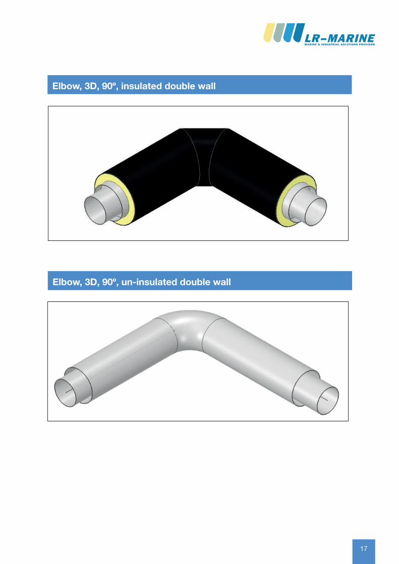
Elbow, 3D, 90°, insulated double wallElbow, 3D, 90º, insulated double wall
Elbow, 3D, 90º, un-insulated double wall

18 18
Rev 409-06-2016 Page 30
Service pipe Conduit pipe Weight per pcs.
DN Inches
OD [mm]
WT [mm]
DN Inches OD [mm]
WT [mm]
[kg]
15 ½ 21.3 2.0 40 1½ 48.3 2.0 3.4420 ¾ 26.9 2.0 50 2 60.3 2.0 4.3225 1 33.7 2.0 50 2 60.3 2.0 4.6532 1¼ 42.4 2.0 65 2½ 76,1 2.0 5.8640 1½ 48.3 2.0 65 2½ 76.1 2.0 6.1650 2 60.3 2.0 80 3 88.9 2.0 7.3865 2½ 76.1 2.0 100 4 114.3 2.0 9.4280 3 88.9 2.0 100 4 114.3 2.0 10.06100 4 114.3 2.0 125 5 139.7 2.0 12.57125 5 139.7 2.0 150 6 168.3 2.0 15.24150 6 168.3 2.0 200 8 219.1 2.0 19.17200 8 219.1 2.0 250 10 273.0 3.0 31.11250 10 273.0 3.0 300 12 323.9 3.0 44.31300 12 323.9 3.0 350 14 355.6 3.0 50.44
Elbows have lengths of 1 by 1 meter. Other lengths available upon request. Wall thickness may be project specific and selected to bethinner or thicker. The pipe OD may also be supplied as metric.
Elbow, 3D, 90°, un-insulated double wall
Rev 409-06-2016 Page 31
Reductions, concentric and eccentric, insulated single wall
Reductions, concentric and eccentric, insulated single wall
Figure 5 Concentric reducer Figure 4Excentric reducer
Reductions, concentric and eccentric, insulated double wall
Figure 6 Concentric reducer Figure 7 Eccentric reducer
Reductions, concentric and eccentric, un-insulated double wall

1918
Rev 409-06-2016 Page 30
Service pipe Conduit pipe Weight per pcs.
DN Inches
OD [mm]
WT [mm]
DN Inches OD [mm]
WT [mm]
[kg]
15 ½ 21.3 2.0 40 1½ 48.3 2.0 3.4420 ¾ 26.9 2.0 50 2 60.3 2.0 4.3225 1 33.7 2.0 50 2 60.3 2.0 4.6532 1¼ 42.4 2.0 65 2½ 76,1 2.0 5.8640 1½ 48.3 2.0 65 2½ 76.1 2.0 6.1650 2 60.3 2.0 80 3 88.9 2.0 7.3865 2½ 76.1 2.0 100 4 114.3 2.0 9.4280 3 88.9 2.0 100 4 114.3 2.0 10.06100 4 114.3 2.0 125 5 139.7 2.0 12.57125 5 139.7 2.0 150 6 168.3 2.0 15.24150 6 168.3 2.0 200 8 219.1 2.0 19.17200 8 219.1 2.0 250 10 273.0 3.0 31.11250 10 273.0 3.0 300 12 323.9 3.0 44.31300 12 323.9 3.0 350 14 355.6 3.0 50.44
Elbows have lengths of 1 by 1 meter. Other lengths available upon request. Wall thickness may be project specific and selected to bethinner or thicker. The pipe OD may also be supplied as metric.
Elbow, 3D, 90°, un-insulated double wall
Rev 409-06-2016 Page 31
Reductions, concentric and eccentric, insulated single wall
Reductions, concentric and eccentric, insulated single wall
Figure 5 Concentric reducer Figure 4Excentric reducer
Reductions, concentric and eccentric, insulated double wall
Figure 6 Concentric reducer Figure 7 Eccentric reducer
Reductions, concentric and eccentric, un-insulated double wall
19
Rev 409-06-2016 Page 34
Straight tee, insulated single wallStraight tee, insulated single wall
Straight tee, insulated double wall
2020
Rev 409-06-2016 Page 36
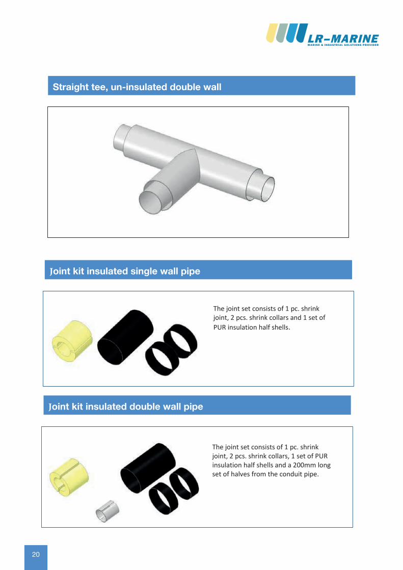
Straight tee, un-insulated double wallStraight tee, un-insulated double wall
The joint set consists of 1 pc. shrink joint, 2 pcs. shrink collars and 1 set of PUR insulation half shells.
Joint kit insulated single wall pipe
The joint set consists of 1 pc. shrink joint, 2 pcs. shrink collars, 1 set of PUR insulation half shells and a 200mm long set of halves from the conduit pipe.
Joint kit insulated double wall pipe
2120
Rev 409-06-2016 Page 36
Straight tee, un-insulated double wallStraight tee, un-insulated double wall
The joint set consists of 1 pc. shrink joint, 2 pcs. shrink collars and 1 set of PUR insulation half shells.
Joint kit insulated single wall pipe
The joint set consists of 1 pc. shrink joint, 2 pcs. shrink collars, 1 set of PUR insulation half shells and a 200mm long set of halves from the conduit pipe.
Joint kit insulated double wall pipe
21
Rev 409-06-2016 Page 42
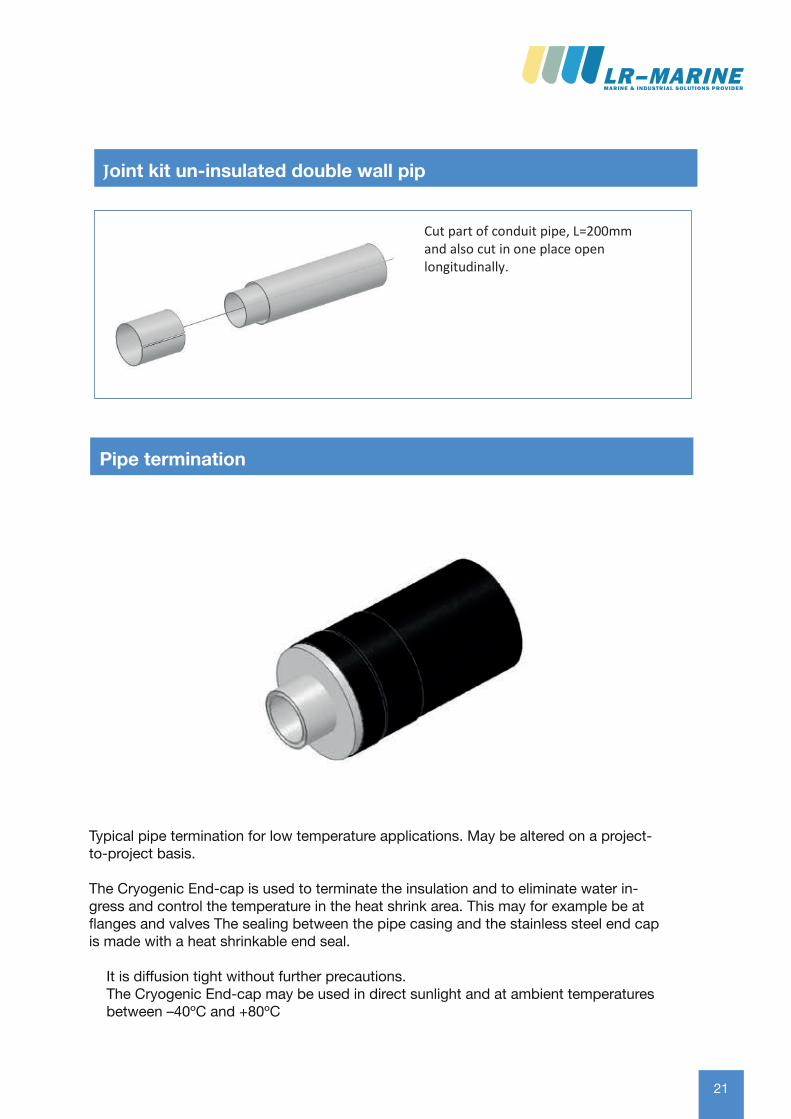
Cut part of conduit pipe, L=200mm and also cut in one place open longitudinally.
Installation of joint kit un-insulated double wall pipeJoint kit un-insulated double wall pip
Pipe termination
Typical pipe termination for low temperature applications. May be altered on a project-to-project basis.
The Cryogenic End-cap is used to terminate the insulation and to eliminate water in-gress and control the temperature in the heat shrink area. This may for example be at flanges and valves The sealing between the pipe casing and the stainless steel end cap is made with a heat shrinkable end seal.
It is diffusion tight without further precautions.The Cryogenic End-cap may be used in direct sunlight and at ambient temperatures between –40ºC and +80ºC
22 22
Rev 409-06-2016 Page 42
Cut part of conduit pipe, L=200mmand also cut in one place openlongitudinally.
Place part of conduit pipe onto oneconduit pipe end temporarily.
Weld service pipe together, and performx-ray and pressure testing.
Slide part of conduit pipe back to theopening and weld both longitudinallyand circularly.Perform x-ray and then pressure test the conduit pipe.
Installation of joint kit un-insulated double wall pipe
Rev 409-06-2016 Page 43
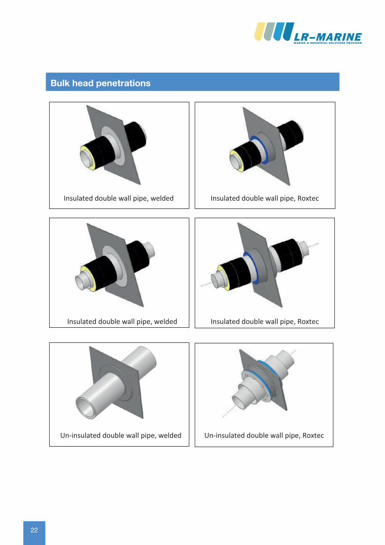
Insulated double wall pipe, welded Insulated double wall pipe, Roxtec
Insulated double wall pipe, welded Insulated double wall pipe, Roxtec
Un-insulated double wall pipe, welded Un-insulated double wall pipe, Roxtec
Bulk head penetrationsBulk head penetrations
2322
Rev 409-06-2016 Page 42
Cut part of conduit pipe, L=200mmand also cut in one place openlongitudinally.
Place part of conduit pipe onto oneconduit pipe end temporarily.
Weld service pipe together, and performx-ray and pressure testing.
Slide part of conduit pipe back to theopening and weld both longitudinallyand circularly.Perform x-ray and then pressure test the conduit pipe.
Installation of joint kit un-insulated double wall pipe
Rev 409-06-2016 Page 43
Insulated double wall pipe, welded Insulated double wall pipe, Roxtec
Insulated double wall pipe, welded Insulated double wall pipe, Roxtec
Un-insulated double wall pipe, welded Un-insulated double wall pipe, Roxtec
Bulk head penetrationsBulk head penetrations
23
Rev 409-06-2016 Page 46
Typical support. This varies from project to project and is not always in LR Marine scopeof supply
Pipe support, un-insulated pipe
Rev 409-06-2016 Page 47
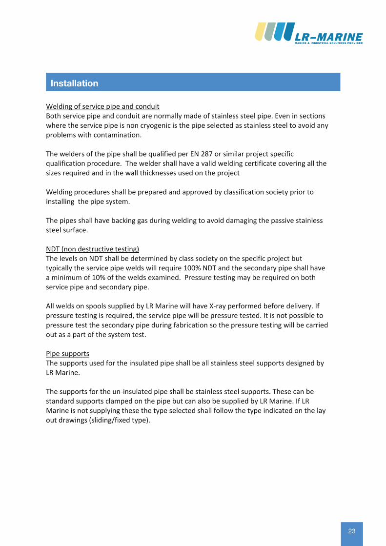
Welding of service pipe and conduit Both service pipe and conduit are normally made of stainless steel pipe. Even in sections where the service pipe is non cryogenic is the pipe selected as stainless steel to avoid any problems with contamination.
The welders of the pipe shall be qualified per EN 287 or similar project specific qualification procedure. The welder shall have a valid welding certificate covering all the sizes required and in the wall thicknesses used on the project
Welding procedures shall be prepared and approved by classification society prior to installing the pipe system.
The pipes shall have backing gas during welding to avoid damaging the passive stainless steel surface.
NDT (non destructive testing) The levels on NDT shall be determined by class society on the specific project but typically the service pipe welds will require 100% NDT and the secondary pipe shall have a minimum of 10% of the welds examined. Pressure testing may be required on both service pipe and secondary pipe.
All welds on spools supplied by LR Marine will have X-ray performed before delivery. If pressure testing is required, the service pipe will be pressure tested. It is not possible to pressure test the secondary pipe during fabrication so the pressure testing will be carried out as a part of the system test.
Pipe supports The supports used for the insulated pipe shall be all stainless steel supports designed by LR Marine.
The supports for the un-insulated pipe shall be stainless steel supports. These can be standard supports clamped on the pipe but can also be supplied by LR Marine. If LR Marine is not supplying these the type selected shall follow the type indicated on the lay out drawings (sliding/fixed type).
InstallationInstallation