Embed Size (px)
Citation preview
30
V8.
3 04
.201
5•S
ubje
ct to
mod
ifica
tion
Technical data
UL marked actuators is optional, please contact your local Sales Representative for details.
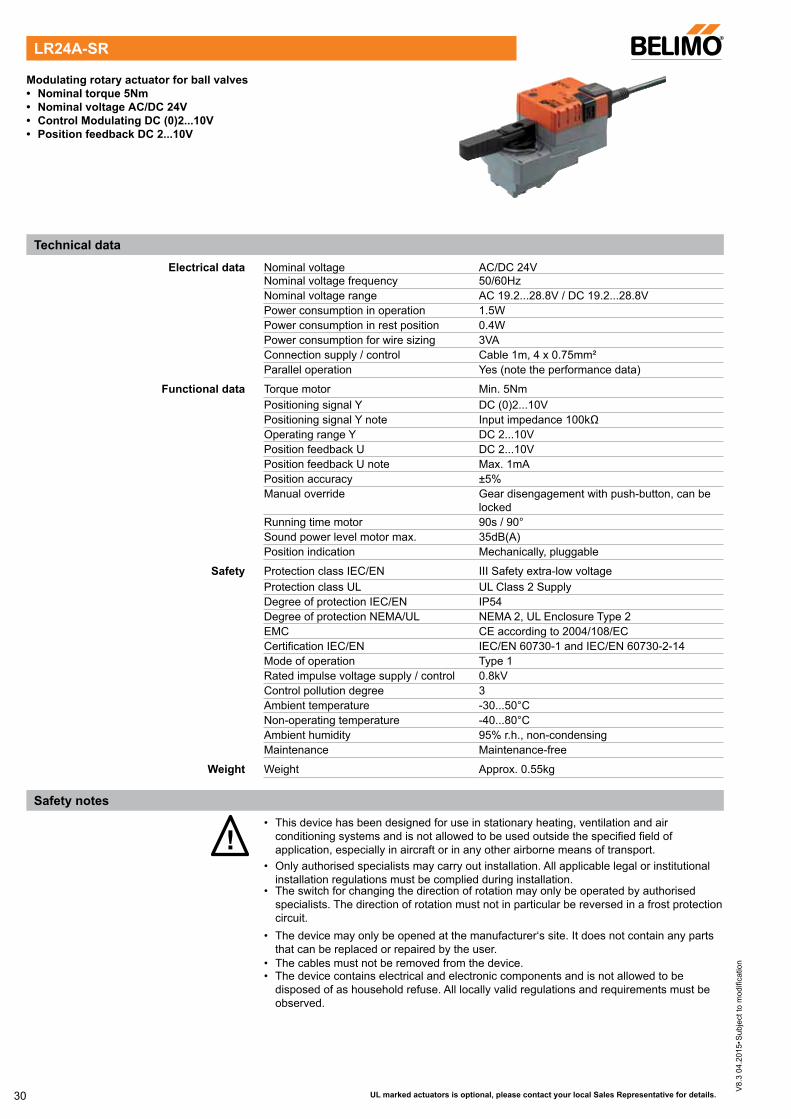
Modulating rotary actuator for ball valves• Nominal torque 5Nm• Nominal voltage AC/DC 24V• Control Modulating DC (0)2...10V• Position feedback DC 2...10V
Electrical data Nominal voltage AC/DC 24V Nominal voltage frequency 50/60Hz Nominal voltage range AC 19.2...28.8V / DC 19.2...28.8V Power consumption in operation 1.5W Power consumption in rest position 0.4W Power consumption for wire sizing 3VA Connection supply / control Cable 1m, 4 x 0.75mm² Parallel operation Yes (note the performance data)
Functional data Torque motor Min. 5Nm Positioning signal Y DC (0)2...10V Positioning signal Y note Input impedance 100kΩ Operating range Y DC 2...10V Position feedback U DC 2...10V Position feedback U note Max. 1mA Position accuracy ±5% Manual override Gear disengagement with push-button, can be
locked Running time motor 90s / 90° Sound power level motor max. 35dB(A) Position indication Mechanically, pluggable
Safety Protection class IEC/EN III Safety extra-low voltage Protection class UL UL Class 2 Supply Degree of protection IEC/EN IP54 Degree of protection NEMA/UL NEMA 2, UL Enclosure Type 2 EMC CE according to 2004/108/EC Certification IEC/EN IEC/EN 60730-1 and IEC/EN 60730-2-14 Mode of operation Type 1 Rated impulse voltage supply / control 0.8kV Control pollution degree 3 Ambient temperature -30...50°C Non-operating temperature -40...80°C Ambient humidity 95% r.h., non-condensing Maintenance Maintenance-free
Weight Weight Approx. 0.55kg
!• This device has been designed for use in stationary heating, ventilation and air
conditioning systems and is not allowed to be used outside the specified field of application, especially in aircraft or in any other airborne means of transport.
• Only authorised specialists may carry out installation. All applicable legal or institutional installation regulations must be complied during installation.
• The switch for changing the direction of rotation may only be operated by authorised specialists. The direction of rotation must not in particular be reversed in a frost protection circuit.
• The device may only be opened at the manufacturer‘s site. It does not contain any parts that can be replaced or repaired by the user.
• The cables must not be removed from the device.• The device contains electrical and electronic components and is not allowed to be
disposed of as household refuse. All locally valid regulations and requirements must be observed.
LR24A-SR
Safety notes
31
V8.
3 04
.201
5•S
ubje
ct to
mod
ifica
tion
UL marked actuators is optional, please contact your local Sales Representative for details.
Mode of operation The actuator is connected with a standard modulating signal of DC (0)2...10V and travels to the position defined by the positioning signal. Measuring voltage U serves for the electrical display of the valve position 0...100% and as slave control signal for other actuators.
Simple direct mounting Straightforward direct mounting on the ball valve with only one central screw. The assembly tool is integrated in the plug-in position indication. The mounting position in relation to the ball valve can be selected in 90° steps.
Manual override Manual override with push-button possible (the gear is disengaged for as long as the button is pressed or remains locked).
High functional reliability The actuator is overload protected, requires no limit switches and automatically stops when the end stop is reached.
Adjustable angle of rotation Adjustable angle of rotation with mechanical end stops.
Description TypeElectrical accessories Auxiliary switch, add-on, 1 x SPDT S1A
Auxiliary switch, add-on, 2 x SPDT S2A Feedback potentiometer 140 Ohm, add-on P140A Feedback potentiometer 200 Ohm, add-on P200A Feedback potentiometer 500 Ohm, add-on P500A Feedback potentiometer 1 kOhm, add-on P1000A Feedback potentiometer 2.8 kOhm, add-on P2800A Feedback potentiometer 5 kOhm, add-on P5000A Feedback potentiometer 10 kOhm, add-on P10000A
!Notes • Connection via safety isolating transformer.
• Parallel connection of other actuators possible. Observe the performance data.• Direction of rotation switch is covered. Factory setting: Direction of rotation Y2.
Wiring diagrams
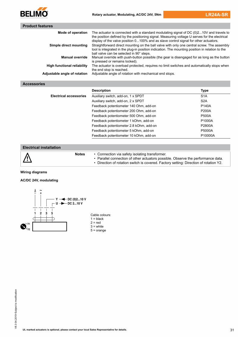
AC/DC 24V, modulating
Y2
Y1
Y U
1 32 5
DC 2...10 VDC (0)2...10 V
–
T ~
+
Cable colours:1 = black 2 = red 3 = white 5 = orange
Rotary actuator, Modulating, AC/DC 24V, 5Nm LR24A-SR
Product features
Accessories
Electrical installation
32
V8.
3 04
.201
5•S
ubje
ct to
mod
ifica
tion
UL marked actuators is optional, please contact your local Sales Representative for details.
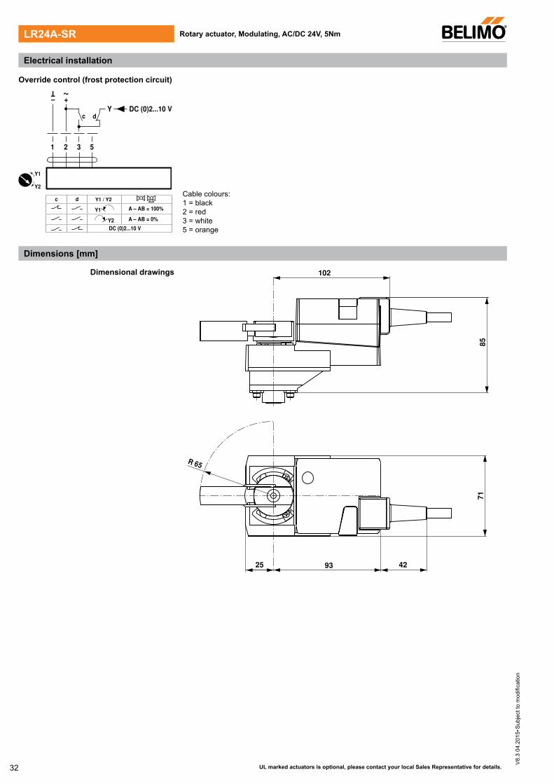
Override control (frost protection circuit)
Y
1 32
DC (0)2...10 V– +
T ~
c d
5
c d
Y1 A – AB = 100%
Y2 A – AB = 0%
DC (0)2...10 V
Y1 / Y2
Y2
Y1
Cable colours:1 = black 2 = red 3 = white 5 = orange
25
102
85
93
71
R 65
42
Electrical installation
Dimensions [mm]
Rotary actuator, Modulating, AC/DC 24V, 5NmLR24A-SR
Dimensional drawings

33
V8.
3 04
.201
5•S
ubje
ct to
mod
ifica
tion
Technical data
UL marked actuators is optional, please contact your local Sales Representative for details.
Rotary actuator for ball valves• Nominal torque 5Nm• Nominal voltage AC/DC 24V • Control Open-close, 3-point
Electrical data Nominal voltage AC/DC 24V Nominal voltage frequency 50/60Hz Nominal voltage range AC 19.2...28.8V / DC 19.2...28.8V Power consumption in operation 1.5W Power consumption in rest position 0.2W Power consumption for wire sizing 2VA Connection supply / control Cable 1m, 3 x 0.75mm² Parallel operation Yes (note the performance data)
Functional data Torque motor Min. 5Nm Manual override Gear disengagement with push-button, can be
locked Running time motor 90s / 90° Sound power level motor max. 35 dB(A) Position indication Mechanically, pluggable
Safety Protection class IEC/EN III Safety extra-low voltage Protection class UL UL Class 2 Supply Degree of protection IEC/EN IP54 Degree of protection NEMA/UL NEMA 2, UL Enclosure Type 2 EMC CE according to 2004/108/EC Certification IEC/EN IEC/EN 60730-1 and IEC/EN 60730-2-14 Mode of operation Type 1 Rated impulse voltage supply / control 0.8kV Control pollution degree 3 Ambient temperature -30...50°C Non-operating temperature -40...80°C Ambient humidity 95% r.h., non-condensing Maintenance Maintenance-free
Weight Weight Approx. 0.55kg
!• This device has been designed for use in stationary heating, ventilation and air
conditioning systems and is not allowed to be used outside the specified field of application, especially in aircraft or in any other airborne means of transport.
• Only authorised specialists may carry out installation. All applicable legal or institutional installation regulations must be complied during installation.
• The switch for changing the direction of rotation may only be operated by authorised specialists. The direction of rotation must not in particular be reversed in a frost protection circuit.
• The device may only be opened at the manufacturer‘s site. It does not contain any parts that can be replaced or repaired by the user.
• The cables must not be removed from the device.• The device contains electrical and electronic components and is not allowed to be
disposed of as household refuse. All locally valid regulations and requirements must be observed.
LR24A
Safety notes
34
V8.
3 04
.201
5•S
ubje
ct to
mod
ifica
tion
UL marked actuators is optional, please contact your local Sales Representative for details.
Simple direct mounting Straightforward direct mounting on the ball valve with only one central screw. The assembly tool is integrated in the plug-in position indication. The mounting position in relation to the ball valve can be selected in 90° steps.
Manual override Manual override with push-button possible (the gear is disengaged for as long as the button is pressed or remains locked).
High functional reliability The actuator is overload protected, requires no limit switches and automatically stops when the end stop is reached.
Adjustable angle of rotation Adjustable angle of rotation with mechanical end stops.
Description TypeElectrical accessories Auxiliary switch, add-on, 1 x SPDT S1A
Auxiliary switch, add-on, 2 x SPDT S2A Feedback potentiometer 140 Ohm, add-on P140A Feedback potentiometer 200 Ohm, add-on P200A Feedback potentiometer 500 Ohm, add-on P500A Feedback potentiometer 1 kOhm, add-on P1000A Feedback potentiometer 2.8 kOhm, add-on P2800A Feedback potentiometer 5 kOhm, add-on P5000A Feedback potentiometer 10 kOhm, add-on P10000A
Rotary actuator, Open-close, 3-point, AC/DC 24V, 5Nm
!Notes • Connection via safety isolating transformer.
• Parallel connection of other actuators possible. Observe the performance data.• Direction of rotation switch is covered. Factory setting: Direction of rotation Y2.
Wiring diagrams
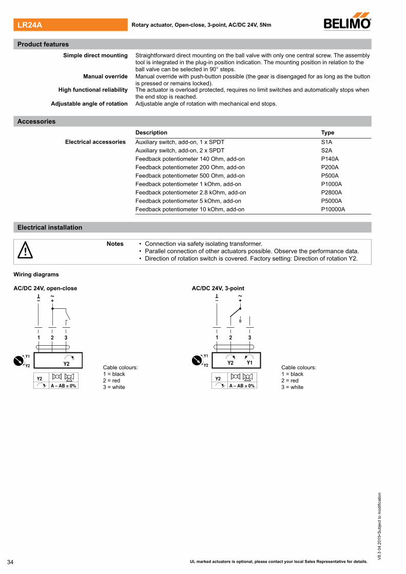
AC/DC 24V, open-close AC/DC 24V, 3-point
1 2 3
Y2
– +
T ~
Y2 A – AB = 0%
Y2
Y1
Cable colours:1 = black 2 = red 3 = white
1 2 3
0
Y1 Y2
– +
T ~
Y2 A – AB = 0%
Y2
Y1
Cable colours:1 = black 2 = red 3 = white
Product features
Electrical installation
LR24A
Accessories
35
V8.
3 04
.201
5•S
ubje
ct to
mod
ifica
tion
UL marked actuators is optional, please contact your local Sales Representative for details.
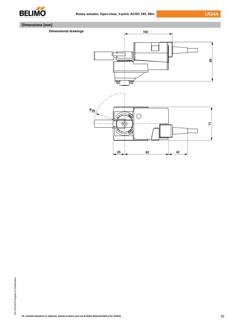
25
102
85
93
71
R 65
42
Dimensions [mm]
Rotary actuator, Open-close, 3-point, AC/DC 24V, 5Nm LR24A
Dimensional drawings
36
V8.
3 04
.201
5•S
ubje
ct to
mod
ifica
tion
Technical data
UL marked actuators is optional, please contact your local Sales Representative for details.
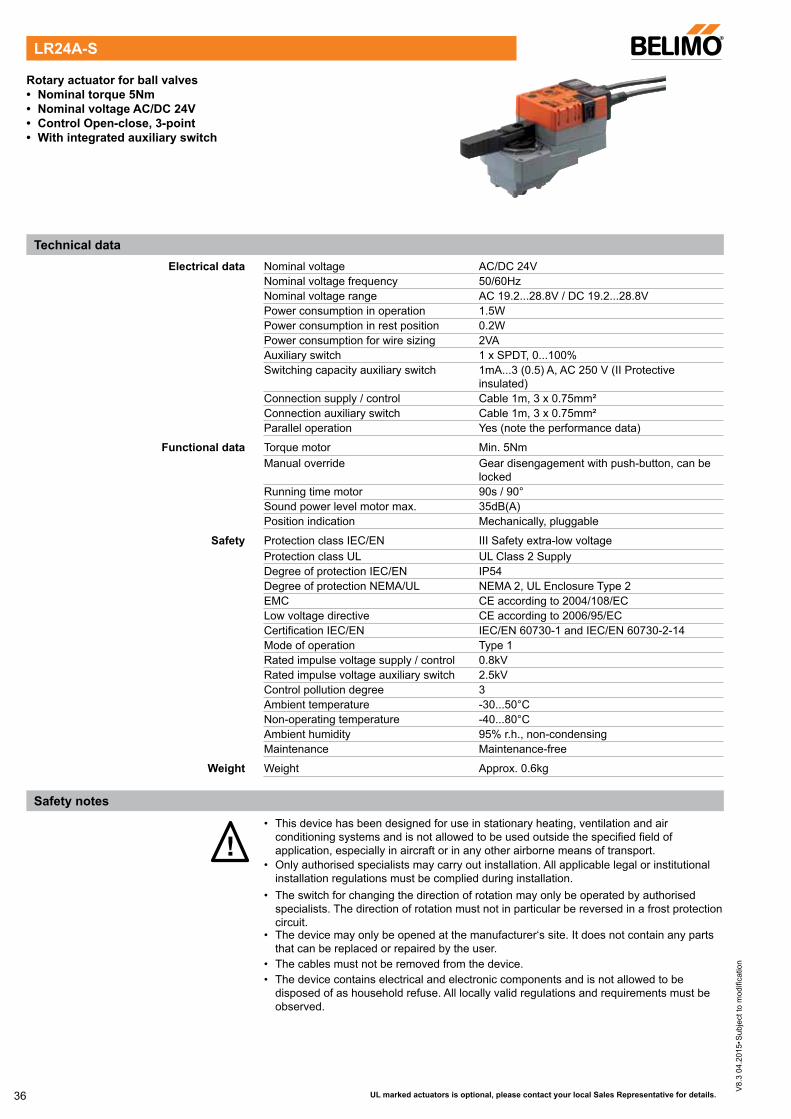
Rotary actuator for ball valves• Nominal torque 5Nm• Nominal voltage AC/DC 24V• Control Open-close, 3-point• With integrated auxiliary switch
Electrical data Nominal voltage AC/DC 24V Nominal voltage frequency 50/60Hz Nominal voltage range AC 19.2...28.8V / DC 19.2...28.8V Power consumption in operation 1.5W Power consumption in rest position 0.2W Power consumption for wire sizing 2VA Auxiliary switch 1 x SPDT, 0...100% Switching capacity auxiliary switch 1mA...3 (0.5) A, AC 250 V (II Protective
insulated) Connection supply / control Cable 1m, 3 x 0.75mm² Connection auxiliary switch Cable 1m, 3 x 0.75mm² Parallel operation Yes (note the performance data)
Functional data Torque motor Min. 5Nm Manual override Gear disengagement with push-button, can be
locked Running time motor 90s / 90° Sound power level motor max. 35dB(A) Position indication Mechanically, pluggable
Safety Protection class IEC/EN III Safety extra-low voltage Protection class UL UL Class 2 Supply Degree of protection IEC/EN IP54 Degree of protection NEMA/UL NEMA 2, UL Enclosure Type 2 EMC CE according to 2004/108/EC Low voltage directive CE according to 2006/95/EC Certification IEC/EN IEC/EN 60730-1 and IEC/EN 60730-2-14 Mode of operation Type 1 Rated impulse voltage supply / control 0.8kV Rated impulse voltage auxiliary switch 2.5kV Control pollution degree 3 Ambient temperature -30...50°C Non-operating temperature -40...80°C Ambient humidity 95% r.h., non-condensing Maintenance Maintenance-free
Weight Weight Approx. 0.6kg
!• This device has been designed for use in stationary heating, ventilation and air
conditioning systems and is not allowed to be used outside the specified field of application, especially in aircraft or in any other airborne means of transport.
• Only authorised specialists may carry out installation. All applicable legal or institutional installation regulations must be complied during installation.
• The switch for changing the direction of rotation may only be operated by authorised specialists. The direction of rotation must not in particular be reversed in a frost protection circuit.
• The device may only be opened at the manufacturer‘s site. It does not contain any parts that can be replaced or repaired by the user.
• The cables must not be removed from the device.• The device contains electrical and electronic components and is not allowed to be
disposed of as household refuse. All locally valid regulations and requirements must be observed.
LR24A-S
Safety notes
37
V8.
3 04
.201
5•S
ubje
ct to
mod
ifica
tion
UL marked actuators is optional, please contact your local Sales Representative for details.
Simple direct mounting Straightforward direct mounting on the ball valve with only one central screw. The assembly tool is integrated in the plug-in position indication. The mounting position in relation to the ball valve can be selected in 90° steps.
Manual override Manual override with push-button possible (the gear is disengaged for as long as the button is pressed or remains locked).
High functional reliability The actuator is overload protected, requires no limit switches and automatically stops when the end stop is reached.
Adjustable angle of rotation Adjustable angle of rotation with mechanical end stops.
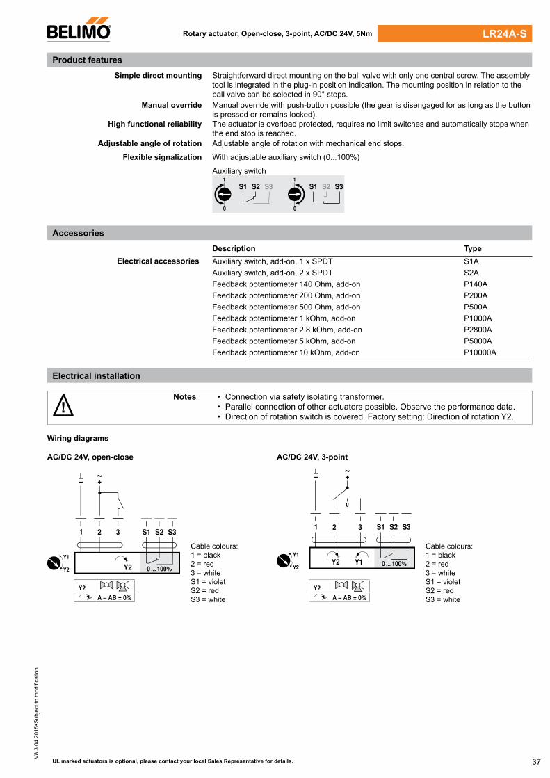
Flexible signalization With adjustable auxiliary switch (0...100%)
Auxiliary switch
S1 S2 S31
0
S1 S2 S31
0
Description TypeElectrical accessories Auxiliary switch, add-on, 1 x SPDT S1A
Auxiliary switch, add-on, 2 x SPDT S2A Feedback potentiometer 140 Ohm, add-on P140A Feedback potentiometer 200 Ohm, add-on P200A Feedback potentiometer 500 Ohm, add-on P500A Feedback potentiometer 1 kOhm, add-on P1000A Feedback potentiometer 2.8 kOhm, add-on P2800A Feedback potentiometer 5 kOhm, add-on P5000A Feedback potentiometer 10 kOhm, add-on P10000A
Rotary actuator, Open-close, 3-point, AC/DC 24V, 5Nm
Product features
Electrical installation
Accessories
LR24A-S
!Notes • Connection via safety isolating transformer.
• Parallel connection of other actuators possible. Observe the performance data.• Direction of rotation switch is covered. Factory setting: Direction of rotation Y2.
Wiring diagrams
AC/DC 24V, open-close
1 2 3
0 ... 100%
S1 S2 S3S3
– +
T ~
Y2
Y2 A – AB = 0%
Y2
Y1
Cable colours:1 = black 2 = red 3 = whiteS1 = violet S2 = red S3 = white
AC/DC 24V, 3-point
1 2 3
0 ... 100%
S1 S2 S3
0
– +
T ~
Y2 Y1
Y2 A – AB = 0%
Y2
Y1Cable colours:1 = black 2 = red 3 = whiteS1 = violet S2 = red S3 = white
38
V8.
3 04
.201
5•S
ubje
ct to
mod
ifica
tion
UL marked actuators is optional, please contact your local Sales Representative for details.
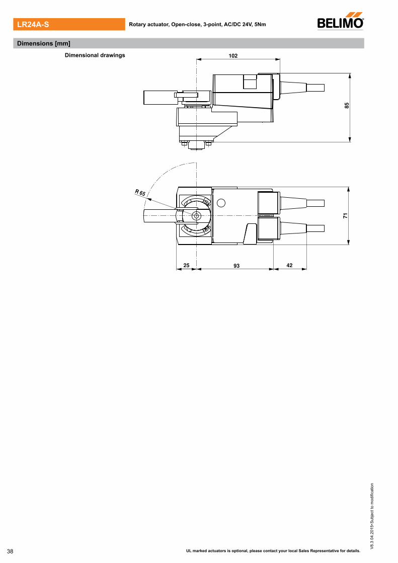
25
102
85
93
71
R 65
42
Dimensions [mm]
Dimensional drawings
Rotary actuator, Open-close, 3-point, AC/DC 24V, 5NmLR24A-S
39
V8.
3 04
.201
5•S
ubje
ct to
mod
ifica
tion
Technical data
UL marked actuators is optional, please contact your local Sales Representative for details.
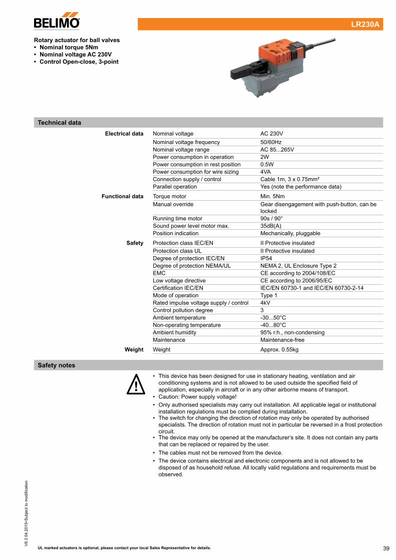
Rotary actuator for ball valves• Nominal torque 5Nm• Nominal voltage AC 230V • Control Open-close, 3-point
Electrical data Nominal voltage AC 230V Nominal voltage frequency 50/60Hz Nominal voltage range AC 85...265V Power consumption in operation 2W Power consumption in rest position 0.5W Power consumption for wire sizing 4VA Connection supply / control Cable 1m, 3 x 0.75mm² Parallel operation Yes (note the performance data)
Functional data Torque motor Min. 5Nm Manual override Gear disengagement with push-button, can be
locked Running time motor 90s / 90° Sound power level motor max. 35dB(A) Position indication Mechanically, pluggable
Safety Protection class IEC/EN II Protective insulated Protection class UL II Protective insulated Degree of protection IEC/EN IP54 Degree of protection NEMA/UL NEMA 2, UL Enclosure Type 2 EMC CE according to 2004/108/EC Low voltage directive CE according to 2006/95/EC Certification IEC/EN IEC/EN 60730-1 and IEC/EN 60730-2-14 Mode of operation Type 1 Rated impulse voltage supply / control 4kV Control pollution degree 3 Ambient temperature -30...50°C Non-operating temperature -40...80°C Ambient humidity 95% r.h., non-condensing Maintenance Maintenance-free
Weight Weight Approx. 0.55kg
!• This device has been designed for use in stationary heating, ventilation and air
conditioning systems and is not allowed to be used outside the specified field of application, especially in aircraft or in any other airborne means of transport.
• Caution: Power supply voltage!• Only authorised specialists may carry out installation. All applicable legal or institutional
installation regulations must be complied during installation.• The switch for changing the direction of rotation may only be operated by authorised
specialists. The direction of rotation must not in particular be reversed in a frost protection circuit.
• The device may only be opened at the manufacturer‘s site. It does not contain any parts that can be replaced or repaired by the user.
• The cables must not be removed from the device.• The device contains electrical and electronic components and is not allowed to be
disposed of as household refuse. All locally valid regulations and requirements must be observed.
LR230A
Safety notes
40
V8.
3 04
.201
5•S
ubje
ct to
mod
ifica
tion
UL marked actuators is optional, please contact your local Sales Representative for details.
Simple direct mounting Straightforward direct mounting on the ball valve with only one central screw. The assembly tool is integrated in the plug-in position indication. The mounting position in relation to the ball valve can be selected in 90° steps.
Manual override Manual override with push-button possible (the gear is disengaged for as long as the button is pressed or remains locked).
High functional reliability The actuator is overload protected, requires no limit switches and automatically stops when the end stop is reached.
Adjustable angle of rotation Adjustable angle of rotation with mechanical end stops.
Description TypeElectrical accessories Auxiliary switch, add-on, 1 x SPDT S1A
Auxiliary switch, add-on, 2 x SPDT S2A Feedback potentiometer 140 Ohm, add-on P140A Feedback potentiometer 200 Ohm, add-on P200A Feedback potentiometer 500 Ohm, add-on P500A Feedback potentiometer 1 kOhm, add-on P1000A Feedback potentiometer 2.8 kOhm, add-on P2800A Feedback potentiometer 5 kOhm, add-on P5000A Feedback potentiometer 10 kOhm, add-on P10000A
Rotary actuator, Open-close, 3-point, AC230 V, 5Nm
!Notes • Caution: Power supply voltage!
• Parallel connection of other actuators possible. Observe the performance data.• Direction of rotation switch is covered. Factory setting: Direction of rotation Y2.
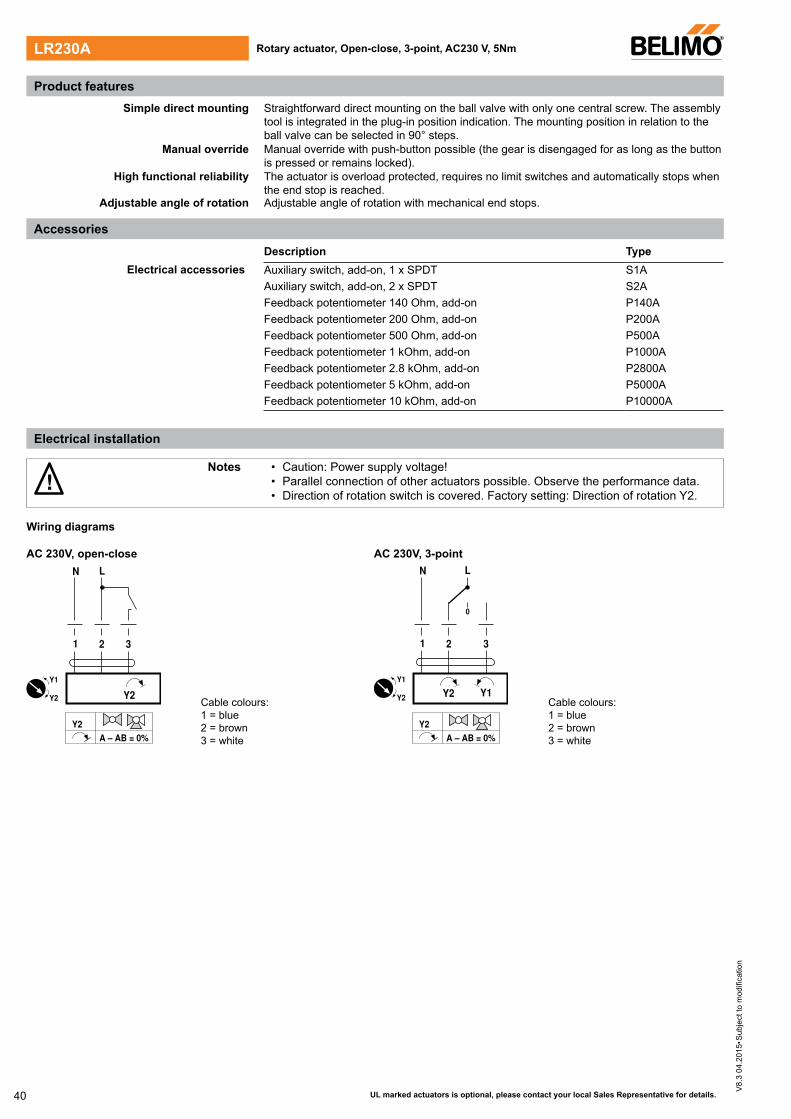
Wiring diagrams
AC 230V, open-close AC 230V, 3-point
1 2 3
Y2
N L
Y2 A – AB = 0%
Y2
Y1
Cable colours:1 = blue 2 = brown 3 = white
1 2 3
0
Y1 Y2
N L
Y2 A – AB = 0%
Y2
Y1
Cable colours:1 = blue 2 = brown 3 = white
LR230A
Product features
Electrical installation
Accessories

41
V8.
3 04
.201
5•S
ubje
ct to
mod
ifica
tion
UL marked actuators is optional, please contact your local Sales Representative for details.
25
102
85
93
71
R 65
42
Dimensions [mm]
Rotary actuator, Open-close, 3-point, AC 230V, 5Nm LR230A
Dimensional drawings
42
V8.
3 04
.201
5•S
ubje
ct to
mod
ifica
tion
Technical data
UL marked actuators is optional, please contact your local Sales Representative for details.
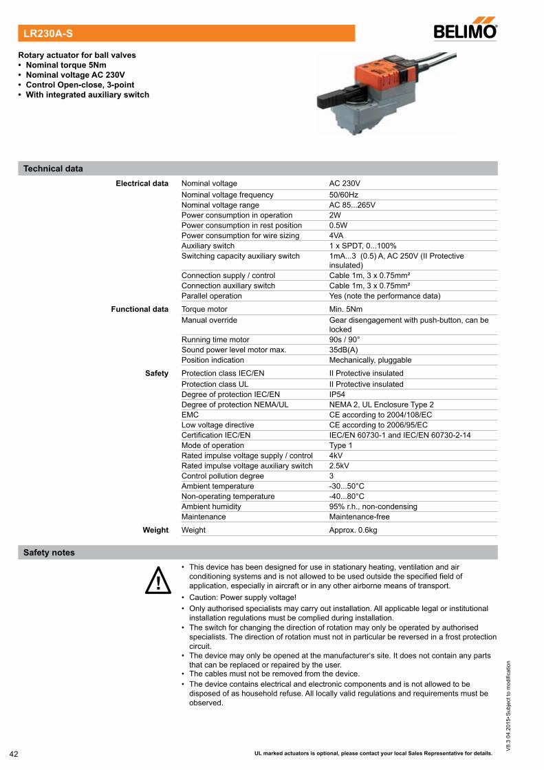
Rotary actuator for ball valves• Nominal torque 5Nm• Nominal voltage AC 230V• Control Open-close, 3-point• With integrated auxiliary switch
Electrical data Nominal voltage AC 230V Nominal voltage frequency 50/60Hz Nominal voltage range AC 85...265V Power consumption in operation 2W Power consumption in rest position 0.5W Power consumption for wire sizing 4VA Auxiliary switch 1 x SPDT, 0...100% Switching capacity auxiliary switch 1mA...3 (0.5) A, AC 250V (II Protective
insulated) Connection supply / control Cable 1m, 3 x 0.75mm² Connection auxiliary switch Cable 1m, 3 x 0.75mm² Parallel operation Yes (note the performance data)
Functional data Torque motor Min. 5Nm Manual override Gear disengagement with push-button, can be
locked Running time motor 90s / 90° Sound power level motor max. 35dB(A) Position indication Mechanically, pluggable
Safety Protection class IEC/EN II Protective insulated Protection class UL II Protective insulated Degree of protection IEC/EN IP54 Degree of protection NEMA/UL NEMA 2, UL Enclosure Type 2 EMC CE according to 2004/108/EC Low voltage directive CE according to 2006/95/EC Certification IEC/EN IEC/EN 60730-1 and IEC/EN 60730-2-14 Mode of operation Type 1 Rated impulse voltage supply / control 4kV Rated impulse voltage auxiliary switch 2.5kV Control pollution degree 3 Ambient temperature -30...50°C Non-operating temperature -40...80°C Ambient humidity 95% r.h., non-condensing Maintenance Maintenance-free
Weight Weight Approx. 0.6kg
!• This device has been designed for use in stationary heating, ventilation and air
conditioning systems and is not allowed to be used outside the specified field of application, especially in aircraft or in any other airborne means of transport.
• Caution: Power supply voltage!• Only authorised specialists may carry out installation. All applicable legal or institutional
installation regulations must be complied during installation.• The switch for changing the direction of rotation may only be operated by authorised
specialists. The direction of rotation must not in particular be reversed in a frost protection circuit.
• The device may only be opened at the manufacturer‘s site. It does not contain any parts that can be replaced or repaired by the user.
• The cables must not be removed from the device.• The device contains electrical and electronic components and is not allowed to be
disposed of as household refuse. All locally valid regulations and requirements must be observed.
Safety notes
LR230A-S
43
V8.
3 04
.201
5•S
ubje
ct to
mod
ifica
tion
UL marked actuators is optional, please contact your local Sales Representative for details.
Simple direct mounting Straightforward direct mounting on the ball valve with only one central screw. The assembly tool is integrated in the plug-in position indication. The mounting position in relation to the ball valve can be selected in 90° steps.
Manual override Manual override with push-button possible (the gear is disengaged for as long as the button is pressed or remains locked).
High functional reliability The actuator is overload protected, requires no limit switches and automatically stops when the end stop is reached.
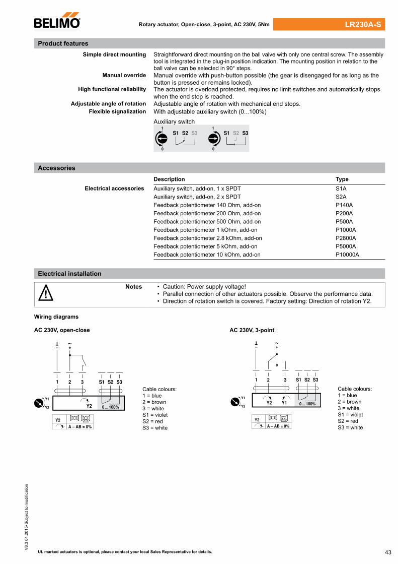
Adjustable angle of rotation Adjustable angle of rotation with mechanical end stops.Flexible signalization With adjustable auxiliary switch (0...100%)
Auxiliary switch
S1 S2 S31
0
S1 S2 S31
0
Description TypeElectrical accessories Auxiliary switch, add-on, 1 x SPDT S1A
Auxiliary switch, add-on, 2 x SPDT S2A Feedback potentiometer 140 Ohm, add-on P140A Feedback potentiometer 200 Ohm, add-on P200A Feedback potentiometer 500 Ohm, add-on P500A Feedback potentiometer 1 kOhm, add-on P1000A Feedback potentiometer 2.8 kOhm, add-on P2800A Feedback potentiometer 5 kOhm, add-on P5000A Feedback potentiometer 10 kOhm, add-on P10000A
Rotary actuator, Open-close, 3-point, AC 230V, 5Nm
Product features
Accessories
Electrical installation
!Notes • Caution: Power supply voltage!
• Parallel connection of other actuators possible. Observe the performance data.• Direction of rotation switch is covered. Factory setting: Direction of rotation Y2.
Wiring diagrams
LR230A-S
AC 230V, open-close
Cable colours:1 = blue 2 = brown 3 = whiteS1 = violet S2 = red S3 = white
AC 230V, 3-point
Cable colours:1 = blue 2 = brown 3 = whiteS1 = violet S2 = red S3 = white
1 2 3
0 ... 100%
S1 S2 S3S3
– +
T ~
Y2
Y2 A – AB = 0%
Y2
Y1
1 2 3
0 ... 100%
S1 S2 S3
0
– +
T ~
Y2 Y1
Y2 A – AB = 0%
Y2
Y1

44
V8.
3 04
.201
5•S
ubje
ct to
mod
ifica
tion
UL marked actuators is optional, please contact your local Sales Representative for details.
25
102
85
93
71
R 65
42
Dimensions [mm]
Dimensional drawings
Rotary actuator, Open-close, 3-point, AC 230V, 5NmLR230A-S


![Atmel AVR1610: Guide to IEC 60730 Class B …ww1.microchip.com/downloads/en/AppNotes/doc42008.pdfAtmel AVR1610: Guide to IEC 60730 Class B Compliance with XMEGA [APPLICATION NOTE]](https://img.pdfslide.net/doc/110x75/5abf9f6d7f8b9add5f8deb78/atmel-avr1610-guide-to-iec-60730-class-b-ww1-avr1610-guide-to-iec-60730-class.jpg)


![IEC 60730-2-9{ed4.1) - Welcome to the IEC Webstoreed4.1}en.pdf · IEC 60730-2-9 edition 4.1 contains the fourth edition (2015-05) [documents 72/990/FDIS and 72/998/RVD] and its amendment](https://img.pdfslide.net/doc/110x75/613c5c5e4c23507cb635553c/iec-60730-2-9ed41-welcome-to-the-iec-webstore-ed41enpdf-iec-60730-2-9.jpg)