Embed Size (px)
Citation preview
LRS Installation GuideFor LRS1 and LRS2 Remote Access Servers

The information in this guide may change without notice. The manufacturer assumes no responsibility for any errors which may appear in this guide.
DEC and LAT are trademarks of Digital Equipment Corporation. Ethernet is a trademark of XEROX Corporation. NetWare is a trademark of Novell Corporation. UNIX is a registered trademark of The Open Group. Windows 95, Windows 98, Windows 2000, and Windows NT are trademarks of Microsoft Corporation.
Copyright 2000, Lantronix. All rights reserved. No part of the contents of this book may be transmitted or reproduced in any form or by any means without the written permission of Lantronix. Printed in the United States of America.
The revision date for this manual is 26 June, 2001
Part Number: 900-175ARev. B
WARNING
This product has been designed to comply with the limits for a Class A digital device pursuant to Part 15 of FCC Rules. These limits are designed to provide reasonable protection against such interference when operating in a commercial environment. This equipment generates, uses, and can radiate radio frequency energy, and if not installed and used in accordance with this guide, may cause harmful interference to radio communications.
Operation of this equipment in a residential area is likely to cause interference in which case the user, at his or her own expense, will be required to take whatever measures may be required to correct the interference.
Changes or modifications to this device not explicitly approved by Lantronix will void the user’s authority to operate this device.
Cet appareil doit se soumettre avec la section 15 des statuts et règlements de FCC. Le fonctionnement est subjecté aux conditions suivantes:
(1) Cet appareil ne doit pas causer une interférence malfaisante.
(2) Cet appareil doît accepter n'importé quelle interférence reìue qui peut causer uneopération indésirable.
The plug on the power cord is the disconnect device. The socket-outlet shall be installed near the equipment and shall be easily accessible.
Das Geraet wird durch austecken des Stromkabels abgeschaltet. Die Anschluss-Steckdose sollte nah am Geraet und leicht zugaenglich sein.

Contents
3-5-7-7-7-8-8-8-8-9-9
-11
1: Introduction.......................................................................... 1-11.1 Overview ......................................................................................... 1-11.2 Configuration................................................................................... 1-11.3 Software........................................................................................... 1-21.4 About the Documentation................................................................ 1-2
2: Installation............................................................................ 2-12.1 Overview ......................................................................................... 2-12.2 LRS1 Product Description............................................................... 2-12.3 LRS1 Installation............................................................................. 2-32.4 LRS2 Installation............................................................................. 2-52.5 Is it Working? .................................................................................. 2-6
3: Configuration ....................................................................... 3-13.1 Overview ......................................................................................... 3-1
3.1.1 EZWebCon Configuration............................................... 3-13.1.2 Command Line Configuration......................................... 3-13.1.3 Front Panel Menu Configuration..................................... 3-1
3.2 Additional Configuration................................................................. 3-33.2.1 Setting the LRS’s IP Address .......................................... 3-3.2.2 Setting a Subnet Mask..................................................... 33.2.3 Privileged Password ........................................................ 33.2.4 Login Password ............................................................... 33.2.5 Setting the Date and Time ............................................... 33.2.6 Setting the Clock ............................................................. 33.2.7 Setting the Timezone....................................................... 33.2.8 Configuring a Timeserver ............................................... 33.2.9 Rebooting the LRS .......................................................... 33.2.10 Restoring Factory Default Settings ............................... 33.2.11 Reloading Flash ROM................................................... 3
A: Contact Information ........................................................... A-1A.1 Problem Report Procedure............................................................. AA.2 Full Contact Information ............................................................... A-
i

Contents
B: Troubleshooting................................................................. B-1B.1 Diagnosing the Error.......................................................................B-1B.2 Power-up Troubleshooting..............................................................B-3B.3 DHCP Troubleshooting...................................................................B-4B.4 BOOTP Troubleshooting ................................................................B-5B.5 RARP Troubleshooting...................................................................B-5B.6 Modem Configuration Checklist.....................................................B-6B.7 Entering Commands at the Boot Prompt ........................................B-6B.8 LRS2 Boot Menu ...........................................................................B-9
C: Pinouts ................................................................................ C-1C.1 Ethernet Connector .........................................................................C-1C.2 Serial Connectors ............................................................................C-1C.3 Modem Wiring................................................................................C-4
D: Updating Software ............................................................. D-1D.1 Obtaining Software ........................................................................ D-1D.2 Reloading Software........................................................................ D-2D.3 Troubleshooting Flash ROM Updates ........................................... D-4
E: Specifications ......................................................................E-1E.1 Power Information...........................................................................E-1E.2 Environmental Limitations..............................................................E-1
Warranty Statement
Declaration of Conformity
Index
ii

1-1
1: Introduction
1.1 OverviewThe Lantronix Remote Access Servers (LRS models) allow packet traffic between your network and remote networks or computers. The servers use modems to offer attached devices as services to the network, and conversely, can provide connections to other devices on the network.
The LRS1 provides one DB25 serial port, an AUI connector, and a UTP (10/100BASE-T) port or BNC (10BASE2) port for Ethernet connections.
The LRS2 provides two DB25 serial ports, a console port, an AUI connector, a UTP (10/100BASE-T) port, and a BNC (10BASE2) port for Ethernet connections.
All models support the AppleTalk, IP, and IPX network protocols, and can support baud rates between 300 and 230400 bits per second.
Note: Throughout the remainder of this manual, all LRS models will be referred to as the LRS unless a distinction needs to be be made between the models.
1.2 ConfigurationThe EZWebCon configuration software (shipped with the on the distribution CD-ROM) is the easiest way to configure the LRS. EZWebCon guides you through configuration via a point and click interface.
Note: Instructions for using EZWebCon are included with the CD-ROM. EZWebCon is also available from the Lantronix FTP and BBS servers and from the Lantronix web site at http://www.lantronix.com. See the LRS Reference Manual for instructions on how to download the software.
Although EZWebCon is the recommended way to configure the server, the unit may also be configured using any of the following methods:
◆ Via Telnet/Rlogin connections to the LRS
◆ Via BOOTP replies from a TCP/IP network host (IP address, loadhost, and download filename only)
◆ Via RARP replies from a TCP/IP host (IP address only)
◆ Via a terminal attached to a serial port (LRS1 and LRS2), or the serial console port (RJ45 port 1 on the LRS16 and LRS32).
◆ Via a configuration file downloaded from a TCP/IP or NetWare host at boot time

Software Introduction
1.3 SoftwareThe LRS stores its executable code in Flash (rewritable) ROM. It is only necessary to download host software to the LRS if you need to update the code in the Flash ROMs with a new version of the software.
Note: For instructions on downloading new software into the LRS, see the Updating Software appendix of the LRS Reference Manual.
1.4 About the DocumentationThis manual explains how to install, initially configure, and start using the LRS. The appendices discuss technical support, troubleshooting, pinouts, and environmental and cabling restrictions.
The LRS Reference Manual explains detailed, conceptual LRS networking concepts. PostScript and browsable HTML versions of the LRS Reference Manual are available on the distribution CD-ROM. In addition, they are available at the Lantronix WWW site, http://www.lantronix.com. To obtain a printed copy of the LRS Reference Manual (part number 900-039), contact Lantronix or your Lantronix distributor.
1-2

2-1
2: Installation
2.1 OverviewThis chapter contains information that the system manager needs to install the LR hardware. The use of industry standard connectors on the serial lines make wiring and connection simple. See Appendix C for more information on the serial cables necessary to connect devices to the LRS.
2.2 LRS1 Product DescriptionThe LRS front panel has a male DB25 serial connector.
Figure 2-1: LRS1 Front Panel
The rear panel has an RJ45 Ethernet connector, a reset button, and a power connector. Use of the network and power connectors are discussed in the following section.
Figure 2-2: LRS1 Rear Panel
Note: When pressed and held during the power up and boot procedures, the Reset button forces the LRS to return to its factory default configuration.
Serial
DB25 Serial Port
RJ45 Ethernet PortReset Button
Power Connector
10BaseT Reset6V DC

LRS1 Product Description Installation
Four LEDs are located on the top of the unit.
Figure 2-3: LRS1 Top Panel showing LEDs
The first LED is a power indicator, and should remain green while the LRS is plugged in. The second is a network link indicator, and should remain green when the LRS is properly connected to the network. Throughout the manual, these LEDs will be referred to as the Power and Link LEDs.
The remaining two LEDs indicate network and serial port activity. They will blink off, yellow, green, or red depending on the current activity. In this manual, these LEDs are referred to as the OK and Serial LEDs.
Note: Although a red LED during boot mode usually signals an error, red LED patterns are part of the normal operation of the LRS and are not necessarily indicative of errors or dangerous operation.
LEDs
2-2

Installation LRS1 Installation
l gure
rity.
2.3 LRS1 InstallationFigure 2-4 displays one example of the LRS installed in a network.
Figure 2-4: Sample Layout
1 Select a location for the LRS
The LRS should be positioned close to the device it will be servicing but out of the way of everyday activity. (See Appendix C, Pinouts, for specific cabling limits.) Since powering down the unit will terminate any active sessions, it may be desirable to place the server in a location secure from unauthorized access. Also, be aware of the environmental operating limits described in Appendix E, Specifications.
2 Connect the LRS to the Ethernet
Connect the 10BASE-T cable to the RJ45 connector on the back of the LRS.
3 Connect the LRS to a serial device
The LRS is designed to connect to an RS232-based serial device. Connect one end of a serial cable to the DB25 connector on the front of the LRS. Connect the other end to your serial device’s DB25 port.
Initially, you may want to connect a terminal to the serial port. The terminal wildisplay any error messages and will allow you to view commands as you confithe LRS.
The serial port is initially set for 9600 baud, 8 data bits, one stop bit, and no pa
4 Supply Power
10BASE-T Hub
Twisted Pair
NetwareFile Server
Sun MicroVAX
LRS1 modem
Remote PC
modem
LRS1Remote Access Server
2-3

LRS1 Installation Installation
m’s
d s.
k the e both
Attach the power cord to the LRS. A secure power connection is necessary for the LRS to function properly. Power will come on automatically when the unit is plugged in, so be sure to use appropriate care when handling the unit.
Ensure that you are using the LRS 6 volt power supply. Many power cubes look similar; however, using a cube with the wrong voltage will damage the unit.Verify that the output voltage on your cube is 6 Volts DC.
Check to see if the Power and Link LEDs on the front of the server light. If not, unplug the server and check the power supply, then check the Ethernet connection and plug the server in again.
The LRS boot-up procedure consists of three steps. During normal operation, the boot process requires approximately 30 seconds to complete.
A The LRS will run through a set of power-up diagnostics for approximately 5 seconds. The Power and Link LEDs should remain solid green; the OK and Serial LEDs will show varying patterns corresponding to the test being run.
The Power and Link LEDs will be solid green if the unit is plugged in and there is a valid network connection.
B The LRS will try to obtain TCP/IP configuration information via BOOTP and RARP. This will take approximately 20 seconds if no hosts answer the request. During this step, the OK LED will blink green approximately three times per second, and occasionally yellow as packets are sent and received.
For more information on BOOTP and RARP, refer to your operating systedocumentation.
C The LRS will determine if the code in the Flash ROMs is valid. If so, it will loathat code and begin normal execution. This takes approximately 5 second
When the unit is running normally, the green OK LED will blink once every twoseconds. If data is being transmitted on the Ethernet port, the OK LED will blinyellow. The Serial LED will blink red when characters are transmitted through serial port, green when characters are received, and yellow when characters artransmitted and received.
2-4
Installation LRS2 Installation
2-5
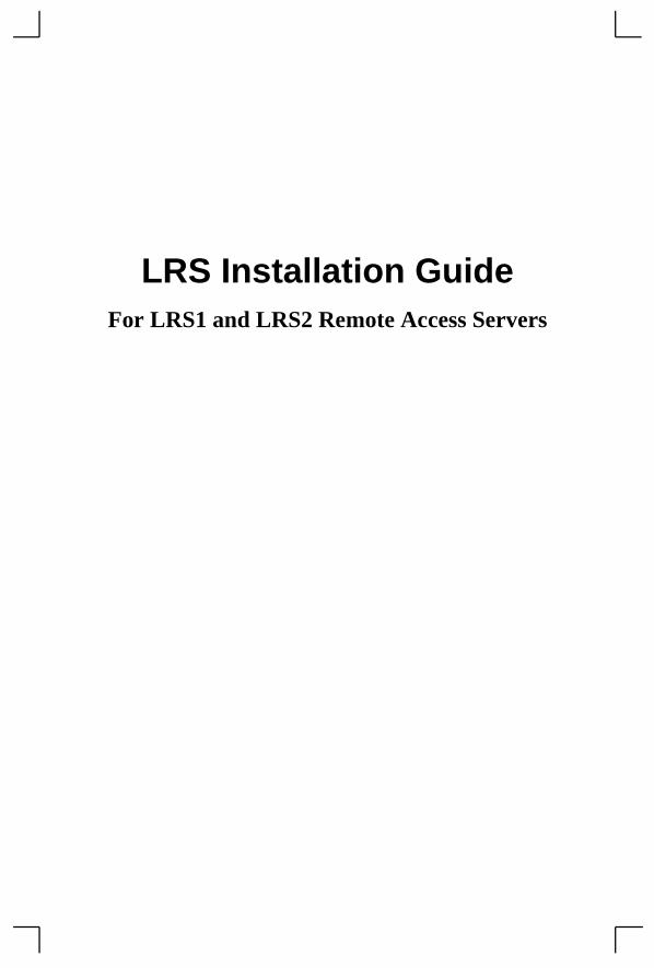
2.4 LRS2 InstallationThe following diagram shows a properly-installed LRS.
Figure 2-5: Sample LRS2 Network Layout
To install the LRS, complete the following steps in order. Refer to the numbers in the previous figure.
1 Connect one or more serial devices to the LRS. See Appendix C, Pinouts, for information on what kinds of device attachments the LRS supports.
2 Connect an Ethernet cable to the Ethernet port.
3 If desired, connect a terminal to the LRS console port (port 1). This will enable you to receive diagnostic and initial configuration messages.
Note: The default serial port settings are 9600 baud, 8 bit characters, and no parity. Refer to Appendix C for more information.
4 Attach one end of the power cable to the LRS and plug the other end into an electrical outlet.
5 Flip the power switch to the ON position. The LRS will go through two steps to begin normal operation:
A It runs through a set of power-up diagnostics for approximately 12 seconds. The LEDs show varying patterns corresponding to the tests being run.
B It tries to obtain TCP/IP configuration information via DHCP, BOOTP, and RARP.
PC withInternalModem
LRS2
Thinwire Terminal(optional)
Modem Modem
LRS2
ModemModem
Phone LinePhone Line
Sun
Terminal(optional)
10BASE-T
10BASE-T Hub

Is it Working? Installation
6 Install EZWebCon on your 32-bit Windows PC. The EZWebCon software is located on the distribution CD-ROM.
2.5 Is it Working?If the LRS appears to be working (the Power and Link LEDs are lit, and the OK LED is blinking slowly) and the unit is connected to the network, there are three ways to confirm that it is working correctly:
1 If you have a terminal attached, try logging in. If the LRS passes power-up diagnostics and you are able to log in, the server is running normally.
2 The EZWebCon installation and configuration software (provided on the distribution CD-ROM) will show any working LRS on the network.
3 If an IP address has been configured for the LRS, ping the LRS from a TCP/IP host.
Note: To configure the LRS when a problem has occurred (for example, the Boot> prompt appears), refer to the Troubleshooting appendix.
Figure 2-6: Pinging the LRS
unix% ping xxx.xxx.xxx.xxx
2-6

and
on s on ME
m a ole rence
3-1
3: Configuration
3.1 OverviewThe LRS may be configured using the EZWebCon configuration software or commands issued at the command line (Local>) prompt.
To configure the LRS when a problem has occurred (for example, the Boot> prompt appears), refer to Appendix B.
3.1.1 EZWebCon ConfigurationThe EZWebCon software, shipped with the LRS, is the easiest way to configure the server. EZWebCon’s point-and-click interface can assist you with both general configurationconfiguration for specific tasks.
UNIX, Macintosh, Windows/Windows NT, and Novell NetWare versions of EZWebCare shipped on the distribution CD-ROM. To use the CD-ROM, refer to the instructionthe CD-ROM case. To install EZWebCon, refer to the appropriate EZWebCon READfile.
Note: To use EZWebCon, NetWare users must run the NetWare VLM Client software.
Note: If you are using a TCP/IP network, the LRS must have an IP address and subnet mask assigned before EZWebCon can be used.
All instructions for using EZWebCon are listed in each README file. Once EZWebCon is running, refer to the EZWebCon on-line help for assistance.
3.1.2 Command Line ConfigurationIf you choose to configure the LRS using the command line interface (accessible froTelnet/Rlogin session, via EZWebCon, or by connecting a terminal to the serial consport) rather than EZWebCon, see the Command Reference chapter of the LRS RefeManual for a detailed list of commands.
Note: SET commands make temporary changes on the server; they are lost once the server is rebooted. DEFINE commands permanently configure the server, but they only take place once the server is rebooted.
3.1.3 Front Panel Menu ConfigurationAfter the LRS2 has booted, the LCD will display a date and time.
Note: The initial date and time may not be correct; see Setting the Date and Time on page 3-7 for configuration instructions.

Overview Configuration
mmand
To display the configuration options, press any of the buttons.
Figure 3-1: Front Panel Buttons
The following options are available:
To navigate between the options, press the left and right buttons.
Pressing the down button will invoke the current menu option (for example, reboot) or will enable you to set an address. The up button acts as an “escape key”; it cancels a coor address edit and displays the top level of options.
Table 3-1: Front Panel Configuration Options
Option Description
IP Address Set the IP address.
Loadhost IP Address Sets the IP address of the loadhost. When the LRS2 is booting, it will download its operational code from this host.
Second IP Host Sets the IP address of a backup loadhost. If the first loadhost can-not be reached during the LRS2 boot process, the operational soft-ware will be downloaded from this host.
IP Subnet Mask Sets the IP subnet mask.
Scan Settings Displays the current software version, LRS2 ethernet (hardware) address, IP address, loadhost IP address, filename of the operation software, secondary loadhost IP address, subnet mask, NetWare server address, and whether BOOTP and RARP are enabled or disabled.
Reboot Reboots the LRS2.
Right ButtonLeft Button
Up Button
Down Button
3-2

Configuration Additional Configuration
u’ve left
nged),
ing) table. ss,
3.2 Additional ConfigurationThis section describes how to configure the IP address, subnet mask, system passwords, incoming logins, and server clock and timezone.
3.2.1 Setting the LRS’s IP AddressThe following methods can be used to set the IP address: the LRS2 front panel buttons, an ARP entry and the Ping command, a BOOTP or an RARP reply, or commands entered from a terminal connected to the DB25 portserial console port.
All methods of setting the address are discussed in the following sections; choose the method that is most convenient for you.
3.2.1.1 Using the Front-Panel ButtonsTo set the IP address using the LRS2 buttons, press the right button until the IP Address option is displayed.
Press the down button. The current IP address will be displayed on the LCD. The first time you configure the LRS2, a row of zeros will be displayed. This indicates that the LRS2 does not have an IP address.
Figure 3-2: LRS2 Without IP Address
To set the address, press the left and right buttons to navigate to the desired digit. Press the up button to increment the digit, and the down button to decrement the digit. When yoset all digits, press the left button until the leftmost digit is underlined, then press thebutton again.
You will be prompted to confirm the address.
Figure 3-3: Prompt to Confirm IP Address
To set this address, press the down button. To cancel (leaving the IP address unchapress the up button.
3.2.1.2 Using an ARP Entry and the Ping CommandIf the LRS has no IP address, it will set its address from the first directed IP ICMP (ppacket it receives. To generate such a packet, create an entry in a UNIX host’s ARPThe entry should specify the intended LRS IP address and its current Ethernet addrelocated on the bottom of the unit.
000.000.000.000
Are you sure?
3-3

Additional Configuration Configuration
Note: Adding an ARP entry requires superuser privileges on the UNIX host and on Windows NT from DOS mode.
Figure 3-4: Adding an Entry to the ARP Table
Note: Command parameters may vary from host to host. Refer to the host documentation for more information.
Then ping the server using the following command:
Figure 3-5: The Ping Command
When the LRS receives the ping packet, it will notice that its IP address is not currently set and will send out broadcasts to see if any other host is using the specified address. If no duplicates are found, the server will use this IP address and will respond to the ping packet. The LRS will not save this learned IP address permanently; it is intended as a temporary measure to enable EZWebCon to communicate with the server or to allow an administrator to Telnet to the remote console port.
Figure 3-6 shows a Telnet connection to the remote console port, designated as port 7000. The LRS will display the remote console port prompt ( # ). In order to successfully log into the port, the login password must be entered at this prompt. The default login password is access.
Note: To change the login password, see Login Password on page 3-7.
Once logged in, the command Define Server Ipaddress n.n.n.n can be entered to make the address permanent.
Figure 3-6: Telnetting to the Remote Console Port
# arp -s 192.0.1.220 00:80:a3:xx:xx:xx
unix% ping 192.0.1.220
% telnet xxx.xxx.xxx.xxx Trying xxx.xxx.xxx.xxxConnected to xxx.xxx.xxx.xxxEscape character is ‘^]’# access (not echoed)Lantronix LRS Version n.n/n (yymmdd)Type Help at the ‘Local>’ prompt for assistance.Enter User-name> jimLocal> SET PRIVILEGEDPassword> system (not echoed)Local>> DEFINE SERVER IPADDRESS 192.0.1.220
3-4

Configuration Additional Configuration
3-5
3.2.1.3 Using a BOOTP or an RARP ReplyAt boot time a host-based BOOTP or RARP server can respond to an LRS request for an available IP address. For information about configuring the BOOTP or RARP servers, see the host documentation. Keep in mind that many BOOTP daemons will not reply to a BOOTP request if the download filename in the configuration file does not exist. If this is the case, create a file with the same pathname specified in the configuration file.
By default, the LRS will attempt BOOTP and RARP queries. You can disable these queries by doing either of the following:
◆ Within EZWebCon, use the Maintenance:Server Boot Parameters menu.
◆ At the Local> prompt (accessible via EZWebCon, a Telnet/Rlogin, or by connecting a terminal to the serial console port), enter the Define Server BOOTP Disabled and Define Server RARP Disabled commands.
3.2.1.4 Using Commands Entered from the Serial Console PortDB25 PortTo define the IP address from the serial console portDB25 port (typically port 1), connect a terminal to the console port and press the Return key.
Note: The default port parameters for the serial console portDB25 port are 9600 baud, 8 bits, no parity, and 1 stop bit. To edit these parameters, see the Ports chapter of the LRS Reference Manual. See Appendix C for pinout information.
If the LRS Boot> prompt appears, the LRS does not have enough information to boot. See Appendix B for a list of Boot Configuration commands which can be used at the Boot> prompt.
If the LRS has already completed booting when you press the Return key, a Username> prompt will be displayed. Once you enter your username, a Local> prompt will be displayed. Become the privileged user (see Privileged Password on page 3-7) and use the Define Server Ipaddress command to set the IP address:
Figure 3-7: Set/Define Server Ipaddress
3.2.2 Setting a Subnet MaskWhen the IP address is configured, a default subnet mask is chosen. If your network is divided into subnetworks, the default subnet mask will not be correct for your network; you must enter a custom subnet mask. A custom subnet mask can be chosen using the front panel buttons or using a command issued at the Local> prompt.
Local>> DEFINE SERVER IPADDRESS 192.0.1.221

Additional Configuration Configuration
left
tton.
to set
in
3.2.2.1 Using the Front-Panel ButtonsTo set the subnet mask using the front panel buttons, press the right button [Figure 3-1 on page 3-2]. A configuration option will be displayed on the LCD. Continue to press the right button until the IP Subnet Mask option is displayed.
Press the down button. The current subnet mask will be displayed on the LCD.
Figure 3-8: Default Subnet Mask
To set the subnet mask, press the right and left buttons to navigate to the desired digit. Press the up button to increment the digit, and the down button to decrement the digit. When you’ve set all digits, press the left button until the leftmost digit is underlined, press thebutton again.
You will be prompted to confirm the subnet mask. To set this mask, press the down buTo cancel (leaving the subnet mask unchanged), press the up button.
3.2.2.2 Using Commands at the Local> PromptThe Local> prompt is accessible from a Telnet/Rlogin session, via EZWebCon, or byconnecting a terminal to the serial console port. Use the Define IP Subnet commandthe subnet mask.
Figure 3-9: Setting Subnet Mask
3.2.2.3 System PasswordsThere are two important passwords on the LRS: the privileged password and the logpassword.
Note: Passwords can be no more than 7 alphanumeric characters. For security purposes, you should use a mix of letters and numbers in each password.
255.255.255.000
Local>> DEFINE IP SUBNET 255.255.192.0
3-6

Configuration Additional Configuration
3-7
3.2.3 Privileged PasswordChanging any server, site, or port setting requires privileged user status. EZWebCon will prompt you for the privileged password when it is needed. If you are not using EZWebCon, you will need to enter the Set Privileged command at the Local> prompt to become the privileged user. The default privileged password on the LRS is system.
Figure 3-10: Set Privileged Command
The prompt will change to reflect privileged user status. Only one user can be the privileged user at a time. If another user is currently logged into the LRS as the privileged user, use the Set Privileged Override command to forcibly become the privileged user.
To change the privileged password, use the Set/Define Server Privileged Password command. Figure 3-11 displays an example of this command.
Figure 3-11: Changing Privileged Password
3.2.4 Login PasswordThe login password is required for remote console logins and for password-protected serial ports. The default login password is access. To change the login password, use the Set/Define Server Login Password command at the Local> prompt. Figure 3-12 displays an example.
Figure 3-12: Changing Login Password
3.2.5 Setting the Date and TimeThe LRS can save the local time, coordinated Universal Time (UTC) (also known as Greenwich Mean Time), standard and Daylight Savings timezones, and the corresponding number of hours difference between UTC and the set timezone.
Local> SET PRIVILEGEDPassword> system (not echoed)Local>>
Local> SET PRIVILEGEDPassword> system (not echoed)Local>> DEFINE SERVER PRIVILEGED PASSWORD “pie4me”
Local> SET PRIVILEGEDPassword> system (not echoed)Local>> DEFINE SERVER LOGIN PASSWORD “82much”

Additional Configuration Configuration
efine se
nes, yed,
e
er. A To r Set/
ine d to
3-8
3.2.6 Setting the ClockUse EZWebCon’s Maintenance feature to set the local date and time, or use the Set/DServer Clock command at the Local> prompt. The following example shows how to uthe Define Server Clock command.
Figure 3-13: Setting the Clock
3.2.7 Setting the TimezoneThe LRS is configured to recognize a number of timezones. To display these timezouse the Show Timezone command at the Local> prompt. If your timezone is not displasee the LRS Reference Manual for instructions on how to set it manually.
Set the timezone by using EZWebCon’s Maintenance feature, or using the Set/DefinServer Timezone command at the Local> prompt:
Figure 3-14: Setting the Timezone
3.2.8 Configuring a Timeserver The LRS regularly verifies and updates its time setting with the designated timeservtimeserver is a host which provides time of day information for nodes on a network. specify a timeserver or backup timeserver, either use the Set/Define IP Timeserver oDefine IPX Timeserver command.
Figure 3-15: Set IP Timeserver Command
3.2.9 Rebooting the LRSRebooting is necessary for three reasons: to make parameters entered with the Defcommand command take effect immediately, to return the unit to factory defaults, anreprogram the Flash ROM.
Local>> DEFINE SERVER CLOCK 14:15:00 12/31/1995
Local>> DEFINE SERVER TIMEZONE US/PACIFIC
Local>> DEFINE IP TIMESERVER 193.0.1.50Local>> DEFINE IP SECONDARY TIMESERVER 193.0.1.51

Configuration Additional Configuration
There are three ways to reboot the LRS:
1 Within EZWebCon, click the Reset button. EZWebCon will prompt you to confirm the reboot; click OK.
2 Using the front panel buttons, select the Reboot option.
3 At the Local> prompt, use the Initialize Server command.
3.2.10 Restoring Factory Default SettingsTo restore the LRS to its factory default configuration, enter the Initialize Server Factory command at the Local> prompt.
3.2.11 Reloading Flash ROMReloading the Flash ROM is necessary if a new version of software is released and you wish to upgrade your unit to this version. To reload the Flash ROM, see the Updating Software appendix of the LRS Reference Manual.
3-9


A-1
A: Contact Information
If you are experiencing an error that is not listed in Appendix B: or if you are unable to fix the error, contact your dealer or Lantronix Technical Support at 800-422-7044 (US) or 949-453-3990. Technical Support is also available via Internet email at [email protected].
A.1 Problem Report ProcedureWhen you report a problem, please provide the following information:
◆ Your name, and your company name, address, and phone number
◆ Lantronix LRS model number
◆ Lantronix LRS serial number
◆ Software version (use the Show Server command to display)
◆ Network configuration, including the information from a Netstat command
◆ Description of the problem
◆ Debug report (stack dump), if applicable
◆ Status of the unit when the problem occurred (please try to include information on user and network activity at the time of the problem)
A.2 Full Contact InformationAddress: 15353 Barranca Parkway, Irvine, CA 92618 USA Phone: 949/453-3990Fax: 949/453-3995World Wide Web: http://www.lantronix.com
North American Direct Sales: 800/422-7055North American Reseller Sales: 800/422-7015North American Sales Fax: 949/450-7232Internet: [email protected]
International Sales: 949/450-7227International Sales Fax: 949/450-7231Internet: [email protected]
Technical Support: 800/422-7044 or 949/453-3990Technical Support Fax: 949/450-7226Internet: [email protected]


error ussed
t
B-1
B: Troubleshooting
This Appendix discusses how to diagnose and fix errors quickly yourself without having to contact a dealer or Lantronix. It will help to connect a terminal to the serial port while diagnosing an error to view any summary messages that are displayed.
When troubleshooting, always ensure that the physical connections (power cable, network cable, and serial cable) are secure. If you have trouble with wireless networking, it may help to connect the LRS to a wired Ethernet network to verify that it is working properly and to check the wireless settings.
Note: Some unexplained errors may be caused by duplicate IP addresses on the network. Make sure that your LRS IP address is unique.
B.1 Diagnosing the ErrorTo properly diagnose an error, connect a terminal to the console port. Take note of any error message displayed on the LCD or on a terminal. Table B-1 lists each error message, and problems that don’t necessarily display a message. If the LCD or terminal displays anmessage that isn’t listed in the following table, try to match the message with one discin the table. If none match, contact your dealer or Lantronix Technical Support.
Table B-1: Error Messages
Problem Error Remedy
Terminal doesn’t display information. Doesn’t display a prompt.
The terminal’s setup is incorrect or there is a connection error.
Check the terminal setup and physical connections. Try another terminal or cable, or try cycling power on the LRS.
Terminal displays a Boot> prompt rather than a Local> prompt
No network is present.
Check the cabling. If you are using the UTP port, check the hub.
Init Noboot was issued at the Local> prompt.
Configure and reboot the LRS, ensure that the button is not depressed.
The Ethernet address is invalid.
Use the Set Server Hardware nn-nn-nn command to set the correct address. Reboothe LRS.
Request BOOTP: no valid reply received
The BOOTP request has failed.
The unit will still boot. Check the BOOTP server’s configuration.
Request RARP: no valid reply received
The RARP request has failed.
The unit will still boot. See your host man pages for RARPD information.

Diagnosing the Error Troubleshooting
Note: If your LRS will not save software in its Flash ROMs, contact your dealer or Lantronix technical support.
Attempting NetWare boot: failed
The NetWare boot has failed.
Make sure that the LRS is using the proper fileserver name, and that the fileserver is running properly. Both devices must be on the same network.Make sure that the LRS is using the complete and correct loadfile pathname, including the drive name. Verify that the loadfile is in the login directory and is world-readable.
The flash needs to be replaced.
Contact your dealer or Lantronix Technical Support for assistance.
File server xxxxxx not found
The NetWare boot has failed.
Make sure that the LRS is using the proper fileserver name, and that the fileserver is running properly. Both devices must be on the same network.
File not found NetWare or TFTP could not locate the appropriate boot file.
Make sure that the LRS is using the complete and correct loadfile pathname, including the drive name. Verify that the loadfile is in the login directory and is world-readable.
Attempting TFTP boot: failed
The TFTP request has failed.The flash needs to be replaced.
See the LRS Reference Manual for TFTP troubleshooting information.Contact your dealer or Lantronix Technical Support for assistance.
Table B-1: Error Messages , cont.
Problem Error Remedy
B-2

Troubleshooting Power-up Troubleshooting
l
B.2 Power-up TroubleshootingProblem situations and error messages are listed in Table B-2. If you cannot find an explanation for your problem, try to match it to one of the other errors. If you cannot remedy the problem, contact your dealer or Lantronix Technical Support.
Table B-2: Power-up Problems and Error Messages
Problem/Message Error Remedy
The LRS is connected to a power source, but there is no LED activity.
The unit or its power supply is damaged.
Contact your dealer or Lantronix Technical Support for a replacement.
The LRS is unable to complete power-up diagnostics.
This generally indicates a hardware fault. One of the LEDs will be solid red for three seconds, followed by one second of another color.
Note the blinking LED and its color, then contact your dealer or Lantronix Technical Support. The LRS will not be operational until the fault is fixed.
The LRS completes its power-up and boot procedures, but there’s no noticeable serial activity.
There is a problem with the serial connection or the set-up of the serial device.
Check the terminal setup and the physicaconnections, including the cable pinouts (see Appendix C). Try another serial device or cable, or cycle power on the LRS.
A rapidly-blinking OK LED may signal boot failure.
Reboot the unit. When the LRS is running normally, the OK LED blinks every two seconds.
B-3

DHCP Troubleshooting Troubleshooting
B.3 DHCP Troubleshooting
The terminal shows a Boot> prompt rather than a Local> prompt.
The LRS is not connected properly to the Ethernet.
Ensure that the LRS is firmly connected to a functional and properly-terminated network node.
The LRS Ethernet address is invalid.
The LRS Ethernet address is located on the bottom of the unit. Use the Change Hardware command to set the correct address, then reboot.
Init Noboot command was entered.
See Entering Commands at the Boot Prompt on page B-6.
The LRS passes power-up diagnostics, but attempts to download new Flash ROM code from a network host.
If the OK LED blinks rapidly, the Flash ROM code may be corrupt.
Reboot the unit. If you get the same message, you will need to reload Flash ROM. See Reloading Software on page D-2.
If you did not request a TFTP boot, the flash ROM code is corrupt. The unit will remain in boot mode.
Table B-3: DHCP Troubleshooting
Area to Check Explanation
DHCP is enabled on the LRS Use the Set/Define Server DHCP Enabled command. If you manually enter an IP address, DHCP is automatically disabled.
Make sure the DHCP server is operational.
Check to see that the DHCP server is on and is functioning correctly.
The LRS gets its IP address from the DHCP server
Refer to the DHCP Manager on your DHCP server for information about addresses in use. If the DHCP server doesn’t list your LRS IP address, there may be a problem.
Table B-2: Power-up Problems and Error Messages, cont.
Problem/Message Error Remedy
B-4

Troubleshooting BOOTP Troubleshooting
r
B.4 BOOTP TroubleshootingIf the BOOTP request is failing and you have configured your host to respond to the request, check these areas:
B.5 RARP Troubleshooting
Table B-4: BOOTP Troubleshooting
Area to Check Explanation
BOOTP is in your system’s /etc/services file
BOOTP must be an uncommented line in /etc/services.
The LRS is in the loadhost’s /etc/hosts file
The LRS must be in this file for the host to answer a BOOTP or TFTP request.
The download file is in the correct directory and is world-readable
The download file must be in the correct directory and world-readable. Specify the complete pathname for the download file in the BOOTP configuration file, or add a default pathname to the download filename.
The LRS and host are in the same IP network
Some hosts will not allow BOOTP replies across IP networks. Either use a host running a different operating system or put the LRS in the same IP network as the host.
Table B-5: RARP Troubleshooting
Area to Check Explanation
The LRS name and hardware address in the host’s /etc/ethers file
The LRS name and hardware address must be in thisfile for the host to answer a RARP request.
The LRS name and IP address in the/etc/hosts file
The LRS name and IP address must be in this file for the host to answer a RARP request.
The operating system Many operating systems do not start a RARP serveat boot time. Check the host’s RARPD documentation for details, or use the ps command to see if there is a RARPD process running.
B-5

Modem Configuration Checklist Troubleshooting
B.6 Modem Configuration ChecklistMost modem problems are caused by cabling mistakes or incorrect modem configuration. However, the following items should be verified after any modem configuration, and re-checked when there is modem trouble.
◆ The modem must disconnect immediately when DTR is de-asserted.
◆ The modem must assert CD (or DSR, if connected) when connected to another mo-dem. It must not assert CD when disconnected. The modem may optionally assert CD during outbound dialing.
◆ The modem and LRS must agree on the flow control method and baud rate scheme.
◆ The modem must not send result codes or messages to the LRS except optionally during outgoing calls.
◆ The modem should be set to restore its configuration from non-volatile memory when DTR is dropped.
◆ The modem should be configured to answer the phone if incoming connections are to be supported. Generally this is done with the ats0=1 command.
◆ The modem should not be configured to answer the phone unless the LRS asserts DTR.
◆ LRS Modem control must be enabled. Using modems on ports without modem con-trol enabled will lead to security problems.
◆ The LRS Autobaud feature should be enabled only when required.
B.7 Entering Commands at the Boot PromptIf the Boot> prompt appears on the serial console instead of the Local> prompt, one of two things may be wrong. Either the LRS does not have enough information to boot, or the network or flash boot has failed. If pressing the Return key does not display a prompt, press any other key. The Boot> prompt should appear.
If the LRS does not have enough information to boot, or the network or flash boot has failed, it will print a message to the console and wait ten seconds for serial port activity. If it detects serial port activity, it will continue booting provided the flash is good. However, if the user presses a key during that time period, the LRS will display the Boot> prompt.
Note: If you see the message “Will attempt another download in x minutes,” press any key for the Boot> prompt.
B-6
Troubleshooting Entering Commands at the Boot Prompt
IP
-
r,
ur
-
f e
t e
es lt.
es lt.
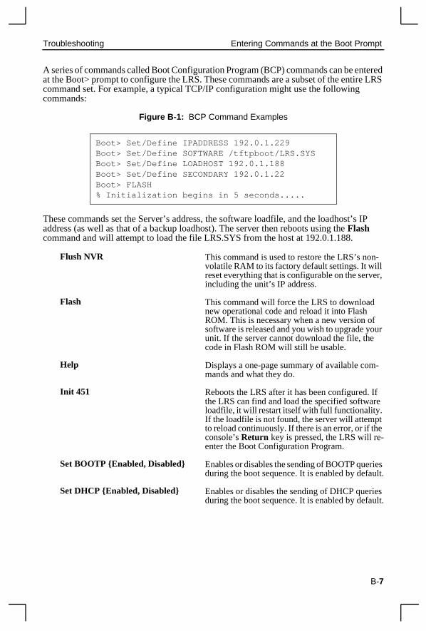
A series of commands called Boot Configuration Program (BCP) commands can be entered at the Boot> prompt to configure the LRS. These commands are a subset of the entire LRS command set. For example, a typical TCP/IP configuration might use the following commands:
Figure B-1: BCP Command Examples
These commands set the Server’s address, the software loadfile, and the loadhost’saddress (as well as that of a backup loadhost). The server then reboots using the Flash command and will attempt to load the file LRS.SYS from the host at 192.0.1.188.
Flush NVR This command is used to restore the LRS’s nonvolatile RAM to its factory default settings. It will reset everything that is configurable on the serveincluding the unit’s IP address.
Flash This command will force the LRS to download new operational code and reload it into Flash ROM. This is necessary when a new version ofsoftware is released and you wish to upgrade younit. If the server cannot download the file, the code in Flash ROM will still be usable.
Help Displays a one-page summary of available commands and what they do.
Init 451 Reboots the LRS after it has been configured. Ithe LRS can find and load the specified softwarloadfile, it will restart itself with full functionality. If the loadfile is not found, the server will attempto reload continuously. If there is an error, or if thconsole’s Return key is pressed, the LRS will re-enter the Boot Configuration Program.
Set BOOTP {Enabled, Disabled} Enables or disables the sending of BOOTP queriduring the boot sequence. It is enabled by defau
Set DHCP {Enabled, Disabled} Enables or disables the sending of DHCP queriduring the boot sequence. It is enabled by defau
Boot> Set/Define IPADDRESS 192.0.1.229Boot> Set/Define SOFTWARE /tftpboot/LRS.SYSBoot> Set/Define LOADHOST 192.0.1.188Boot> Set/Define SECONDARY 192.0.1.22Boot> FLASH% Initialization begins in 5 seconds.....
B-7

Entering Commands at the Boot Prompt Troubleshooting
e
he e
-
. or-
es lt.
e r.
a-r).
up y
s
Set/Define Hardware xx-xx-xx Specifies the last three numbers of the server’s Ethernet address. The first three numbers will bsupplied automatically.
The Ethernet address should have been set at tfactory. Setting an incorrect address could causserious network problems.
Set/Define IPAddress ip_address Specifies this server’s IP address. Uses the standard numeric format.
Set/Define Loadhost ip_address Specifies the host to attempt to load the file fromThe IP address should be in standard numeric fmat (no text names are allowed).
Set/Define RARP {Enabled, Disabled} Enables or disables the sending of RARP queriduring the boot sequence. It is enabled by defau
Set/Define Secondary ip_address Specifies a backup loadhost. The IP address should be in standard numeric format (no text names are allowed). The backup loadhost will bqueried if the primary host cannot load the serve
Set/Define Software filename Specifies the name of the file to load. The LRS will automatically add .SYS to the filename you specify. Note that all protocols must have a filenme specified (either the default or set by the useFor more information, see Appendix D.
TCP/IP users must use the Software option to specify the loadhost, the loadfile, and their own network address.
TFTP users can specify a complete path name (to 31 characters) if the file is located in a directorother than the default.The case of the filename must match that of the filename loaded onto thehost computer.
Show Server Use this command when issuing other commandto view the current LRS setup.
B-8

Troubleshooting LRS2 Boot Menu
or its
B.8 LRS2 Boot Menu The LRS2 Boot Menu offers a number of options that affect how the LRS2 boots. To display this menu, use the Initialize Server Noboot command. The LRS2 will reboot and display the Boot Menu. Alternately, depress one of the front panel buttons and cycle power on the LRS2. Continue to depress the button until the message “Release button” is displayed on the LCD.
The Boot Menu will also display after the LRS2 has been reset to its factory defaults, non-volatile memory (NVR) has been flushed.
The Boot Menu contains the following options:
Table B-6: LRS2 Boot Menu
Boot Menu Option Settings Default
Scan Settings [View only. Displays settings including Hardware (Ethernet) Address and ROM version.]
Reset Options RebootFlush NVRReload Flash
BOOTP BOOTP EnabledBOOTP Disabled
Enabled
RARP RARP EnabledRARP Disabled
Enabled
ENet Interface Using AutoUsing UTPUsing AUIUsing BNC
Using Auto
IP Address (undefined)
Loadhost IP Address (undefined)
Second IP Host (undefined)
NetWare Server (undefined)
Software File (undefined)
B-9


C: Pinouts
C.1 Ethernet ConnectorFigure C-1: RJ45 Ethernet Connector
C.2 Serial Connectors
C.2.1 RJ45 Serial ConnectorsLRS servers are RS-423 compliant, and are thus limited by the equipment at the remote end of the serial line. If the is connected to an RS-232 device, it is subject to RS-232 lim-its: 15m (50 ft.) in length at 9600 baud, and to 2m (6 ft.) at 115.2K baud, although longer lengths will generally work.
Figure C-2: RJ45 Serial Connector
1 2 3 4 5 6 7 8 1 TX+2 TX-3 RX+6 RX-
1 RTS (out)2 DTR (out)3 TX+ (out)4 TX-5 RX-6 RX+ (in)7 DSR (in)8 CTS (in)
1 2 3 4 5 6 7 8
C-1

Serial Connectors Pinouts
C.2.1.1 RJ45 to DB25If you are connecting an RJ45 port to a DTE device (such as a terminal) that has a DB25 connector, you will need to use an RJ45-DTE DB25 adapter. To connect an RJ45 port to a DB25 connector on a DCE device, you will need an RJ45-DCE DB25 adapter. The pinout information for both connections is shown in Figure 0-2.
Figure C-3: Pinouts of RJ45-DB25 Connections
The arrows in Figure 0-2 represent the direction of the signal. The pinouts assume that the 8-conductor cable connecting the LRS and the adapter block is a swapped cable. Both the transmit and receive ground signals on the LRS connector are wired to the signal ground on a DB25 adapter.
Figure C-4: RJ45 to DCE DB25 Adapter
RJ45SerialPort
Cable
6
5
4
3
2
6
5
4
8
7
3
2
1
DTR
RX+
TX+
RX-
TX-
(out)
(out)
(in)
DSR(in)
CTS(in)
RTS
(out)
1
2
3
4
5
6
DTR
RXD
SG
TXD
DSR
RJ45-DB25Adapter
RJ45 DB25
7
8 CTS
RTS4
20
2
7
3
6
5
3
4
5
1
2
6
7
8
6
5
4
8
7
3
2
1
(Server) (terminal)
DTE - DB25 Adapter Pinout
RJ45SerialPort
Cable
6
5
4
3
2
6
5
4
8
7
3
2
1
DTR
RX+
TX+
RX-
TX-
(out)
(out)
(in)
DSR(in)
CTS(in)
RTS
(out)
1
2
3
4
5
6
DCD
TXD
SG
RXD
DTR
RJ45-DB25Adapter
RJ45 DB25
7
8 RTS
CTS5
8
3
7
2
20
4
3
4
5
1
2
6
7
8
6
5
4
8
7
3
2
1
(Server) (modem)
DCE - DB25 Adapter Pinout
DCD
TXD
SG
RXD
DTR
RJ45- DCE DB25wire connectionsRJ45 DB25
RTS
CTS
113
25 14
Back of DB25 connector
DB25 NOTE:This example displaysa male DB25 connector.
If wiring to a female DB25connector, the pinout wil be
exactly the opposite.
ADAPTER NOTE:It is important to wire
the adapter in the correctorientation. The diagram showshow the adapter will look to you
if you are holding it correctly.
Adapter
8 6 4 2
7 5 3 1
(server) (modem)
1
2
3
4
5
6
7
8
5
8
3
7
2
20
4
17
28
C-2

Pinouts Serial Connectors
two
re that to be ers to
at the th the
ound
C-3
You can use a crimper block to connect both transmit and receive grounds from the RJ45 cable to the single signal ground on the DB25. The connector internally “splices” thewires together and provides one wire into the DB25 connector as shown below.
Figure C-5: Wire Splicer
To splice the wires, cut off the end of the wire that does not extend through the connectorand insert both wires into the connector. Make sure that the wire that does not extend through the connector is in as far as possible to ensure a solid connection. Make suthe wire that does extend through the connector extends far enough on the other side inserted in to the DB25 connector. Carefully squeeze the connector using a pair of plimake sure it is fully latched.
C.2.1.2 RJ45 to DB9Figure C-6: RJ45-DTE DB9 Adapter
The arrows in Figure 0-5 represent the direction of the signal. The pinouts assume th8-conductor cable connecting the LRS and the adapter block is a swapped cable. Botransmit and receive ground signals on the LRS connector are wired to the signal gron a DB9 adapter.
The information about crimping the RJ45 ground wires in Section 0.1.1, RJ45 to DB25 ap-plies to the DB9 connector as well.
RJ45 Tx Return
RJ45 Rx Return
Sealed at this end
DB9 Signal Ground
1
2
3
4
5
6
DTR
RXD
SG
TXD
DSR
4
2
5
3
6
RJ45SerialPort
Cable
RJ45-DB9Adapter
RJ45(Server)
DB9(terminal)
3
4
5
1
2
6
7
8
7
8
6
5
4
8
7
3
2
1
6
5
4
3
2
6
5
4
8
7
3
2
1
DTR
RX+
TX+
RX-
TX-
(out)
(out)
(in)
DSR(in)
CTS(in)
RTS
(out)
8
7
CTS
RTS

Modem Wiring Pinouts
be ired
erver a user ecycle ot be
C.2.2 LRS2 Serial ConnectorsThe serial ports on the LRS2 are labeled Console 1, Serial2, and Serial3.
Figure C-7: LRS2 Serial Ports
C.3 Modem Wiring
C.3.1 DSR (Data Signal Ready) versus CD (Car-rier Detect)By default, most modems assert CD only during a valid connection. In this case the mo-dem’s CD pin may be wired to the Server’s DSR pin. Alternately, many modems canconfigured such that DSR acts like CD. In this case, the modem’s DSR pin may be wto the Server’s DSR pin.
C.3.2 DTR (Data Terminal Ready)The MSS normally asserts DTR. When modem control is enabled on the MSS, the swill de-assert DTR for three seconds each time the port is logged out and each time disconnects from a modem service. The modem must be configured to hang up and rwhen DTR is de-asserted. If the modem is not configured in this way, sessions may nproperly disconnected.
DB25 Serial Ports
RJ45 Serial Console Port
C-4
D-1
D: Updating Software
D.1 Obtaining SoftwareCurrent software files (LRS.SYS) are available on the distribution CD. You can obtain software updates and release notes for the LRS from the Lantronix World Wide Web site (www.lantronix.com), or by using anonymous FTP through the Internet (ftp.lantronix.com).
D.1.1 Via the WebThe latest version of LRS.SYS can be downloaded from the Lantronix Web site. At the time of this writing, the exact location of the files on the re-designed site was unkown.
Note: As a result of Netscape Navigator’s configuration, it may try to open the file as an ASCII text file. To avoid this, hold down the shift key when choosing the software file.
D.1.2 Via FTPThe LRS software resides on the Lantronix FTP server (ftp.lantronix.com). Most of these files are binary data, so the binary option must be used to transfer the files. All released files are in the pub directory. Always download the README file in the pub directory before downloading anything else; it contains a list of available software files.
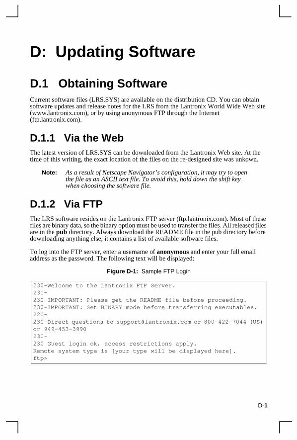
To log into the FTP server, enter a username of anonymous and enter your full email address as the password. The following text will be displayed:
Figure D-1: Sample FTP Login
230-Welcome to the Lantronix FTP Server.230-230-IMPORTANT: Please get the README file before proceeding.230-IMPORTANT: Set BINARY mode before transferring executables.220-230-Direct questions to [email protected] or 800-422-7044 (US) or 949-453-3990230-230 Guest login ok, access restrictions apply.Remote system type is [your type will be displayed here].ftp>

Reloading Software Updating Software
D-2
D.2 Reloading SoftwareThe LRS stores software in Flash ROM to control the initialization process, operation, and command processing. The contents of Flash ROM can be updated by downloading a new version of the operational software via NetWare, TCP/IP, or MOP. Regardless of which protocol is used to update Flash ROM, the following points are important:
◆ The Flash ROM software file name, LRS.SYS, should not be changed.
◆ The download file should be world-readable on the host.
◆ There is a sixteen character length limit for the path name.
◆ There is a twelve character limit for the filename.
◆ Define commands must be used because Set configurations are cleared when the LRS boots. Use the List Server Boot command to check settings before rebooting.
Note: It is important to check LRS settings before using the Initialize Reload command to ensure that you are reloading the correct software file.
D.2.1 Reloading SequenceIf DHCP, BOOTP, or RARP is enabled on the LRS, the LRS will request assistance from a DHCP, BOOTP, or RARP server before starting the download attempts. The LRS will then try TFTP, NetWare, and MOP booting (in that order) provided that it has enough information to try each download method.
Downloading and rewriting the Flash ROM will take approximately two minutes from the time the Initialize command is issued. If the download file cannot be found or accessed, the LRS can be rebooted with the code still in Flash ROM. The OK/ACT LED will blink quickly while the LRS is booting (and reloading code) and then slowly when it returns to normal operation.
Note: If you experience problems reloading Flash ROM, refer to Trouble-shooting Flash ROM Updates on page D-4.
D.2.1.1 TCP/IPBefore the LRS downloads the new software, it will send DHCP, BOOTP, and/or RARP queries (all are enabled by default). Next, the LRS will attempt to download the LRS.SYS file using TFTP (Trivial File Transfer Protocol).
Note: EZWebCon can also be used to reload software.
If a host provides DHCP, BOOTP, or RARP support, it can be used to set the LRS IP address (all methods) and loadhost information (BOOTP and RARP only).
Some BOOTP and TFTP implementations require a specific directory for the LRS.SYS file. See your host’s documentation for instructions.

Updating Software Reloading Software
To manually configure the LRS IP parameters for software reload, use the following commands.
Figure D-2: Configuring TCP/IP Reload
Note: For instructions on how to log into the LRS to enter these commands, see the Getting Started chapter.
The path and filename are case-sensitive and must be enclosed in quotation marks. When attempting to boot across an IP router, you must configure the router to proxy-ARP for the LRS, or use the bootgateway feature. For more information, see Set/Define Bootgateway in the Commands chapter of the Remote Access Server Reference Manual located on the CD-ROM.
D.2.1.2 NetWareThe LRS.SYS file should be placed in the login directory on the NetWare file server. The LRS cannot actually log into the file server (since it knows no username/password); it can only access files in the login directory itself. On the LRS, specify the file server name, filename, and path.
Figure D-3: Configuring NetWare Reload
D.2.1.3 MOPThe LRS.SYS filename is the only parameter that the LRS needs to reload via MOP. Make sure the service characteristic is enabled on the host’s Ethernet circuit, copy the LRS.SYS file to the MOM$LOAD directory, and reload the LRS using the Initialize Reload command. Be sure to use binary mode for the file transfer.
Local> SET PRIVILEGEDPassword> SYSTEM (not echoed)Local>> DEFINE SERVER IPADDRESS nnn.nnn.nnn.nnnLocal>> DEFINE SERVER SOFTWARE “/tftpboot/LRS.SYS”Local>> DEFINE SERVER LOADHOST nnn.nnn.nnn.nnnLocal>> LIST SERVER BOOTLocal>> INITIALIZE RELOAD
Local> SET PRIVILEGEDPassword> SYSTEM (not echoed)Local>> DEFINE SERVER NETWARE LOADHOST fileserverLocal>> DEFINE SERVER SOFTWARE SYS:\LOGIN\LRS.SYSLocal>> INITIALIZE RELOAD
D-3

Troubleshooting Flash ROM Updates Updating Software
D-4
D.3 Troubleshooting Flash ROM UpdatesMany of the problems that occur when updating the Flash ROM can be solved by completing the following steps:
Table D-1: Flash ROM Troubleshooting
Protocol Area to Check
NetWare Ensure the file is in the login directory. Since the LRS cannot actually log into the file server, it has very limited access to the server directories.
TFTP Check the file and directory permissions.
Ensure the loadhost name and address are specified correctly and that their case matches that of the filenames on the host system.
Ensure the file and pathnames are enclosed in quotes to preserve case.
Ensure that TFTP is enabled on the host; several major UNIX vendors ship their systems with TFTP disabled by default.
MOP The Ethernet circuit must have the service characteristic enabled.
Ensure that the MOM$LOAD search path includes the directory containing the LRS.SYS file.

S near
E: Specifications
E.1 Power Information
E.1.1 Power RequirementsVoltage: 110 V AC US, 220 V AC International
Frequency: 47-63 Hz
Operating Current: 700 mA @ 6 V
Power Consumption: 4.2 Watts maximum
Fuse Rating 1.6A, 250 Volts
E.1.2 Power Supply CordCord type: 3 conductors, 1.0 mm2 minimum conductor size (ap-
proximately 18 AWG)
Rated for: 250 Volts AC, 10 Amps
Length: 3.0 meters
E.2 Environmental Limitations
E.2.1 TemperatureOperating range: 5° to 50° C (41° to 122° F)
Storage range: -40° to 66° C (-40° to 151° F)
Max temp. change/hr: 20° C (36° F)
Rapid temperature changes may affect operation. Therefore, do not operate the LRheating or cooling devices, large windows, or doors that open to the outdoors.
E-1
Environmental Limitations Specifications
d
E.2.2 Altitude Operating maximum: 2.4 km (8,000 ft)
Storage maximum: 9.1 km (30,000 ft)
If operating the LRS above 2.4 km (8000 ft.), decrease the operating temperature rating by 1° F for each 1000 ft.
E.2.3 Relative HumidityOperating range: 10% to 90% noncondensing, 40% to 60% recommende
Storage range: 10% to 90% noncondensing
E-2

Warranty Statement
Lantronix warrants for a period of FIVE years from the date of shipment that each LRS1 and LRS2 Remote Access Server supplied shall be free from defects in material and workmanship. During this period, if the customer experiences difficulties with a product and is unable to resolve the problem by phone with Lantronix Technical Support, a Return Material Authorization (RMA) will be issued. Following receipt of a RMA number, the customer is responsible for returning the product to Lantronix, freight prepaid. Lantronix, upon verification of warranty will, at its option, repair or replace the product in question, and return it to the customer freight prepaid. No services are handled at the customer’s site under this warranty.
Lantronix warrants software for a period of sixty (60) days from the date of shipment that each software package supplied shall be free from defects and shall operate according to Lantronix specifications. Any software revisions required hereunder cover supply of distribution media only and do not cover, or include, any installation. The customer is responsible for return of media to Lantronix and Lantronix for freight associated with replacement media being returned to the customer.
Lantronix shall have no obligation to make repairs or to cause replacement required through normal wear and tear of necessitated in whole or in part by catastrophe, fault or negligence of the user, improper or unauthorized use of the Product, or use of the Product in such a manner for which it was not designed, or by causes external to the Product, such as, but not limited to, power or failure of air conditioning.
There are no understandings, agreements, representations or warranties, express or implied, including warranties of merchantability or fitness for a particular purpose, other than those specifically set out above or by any existing contract between the parties. Any such contract states the entire obligation of Lantronix. The contents of this document shall not become part of or modify any prior or existing agreement, commitment or relationship
The information, recommendation, description and safety notations in this or other documents supplied by Lantronix are based on general industry experience and judgment with respect to such hardware and software. THIS INFORMATION SHOULD NOT BE CONSIDERED TO BE ALL INCLUSIVE OR COVERING ALL CONTINGENCIES. NO OTHER WARRANTIES, EXPRESS OR IMPLIED, INCLUDING WARRANTIES OF FITNESS FOR A PARTICULAR PURPOSE OR MERCHANTABILITY, OR WARRANTIES ARISING FROM COURSE OF DEALING OR USAGE OF TRADE, ARE MADE REGARDING THE INFORMATION, RECOMMENDATIONS, DESCRIPTIONS AND SAFETY NOTATIONS CONTAINED HEREBY AND IN HARDWARE AND SOFTWARE SPECIFICATION DOCUMENTATION, OR INSTRUCTIONS SUPPLIED BY Lantronix. In no event will Lantronix be responsible to the user in contract, in tort (including negligence), strict liability or otherwise for any special, indirect, incidental or consequential damage or loss of equipment, plant or power system, cost of capital, loss of profits or revenues, cost of replacement power, additional expenses in the use of existing software, hardware, equipment or facilities, or claims against the user by its employees or customers resulting from the use of the information, recommendations, descriptions and safety notations supplied by Lantronix. Lantronix liability is limited (at its election) to (1) refund of buyer’s purchase price for such affected products (without interest); (2) repair of such products, or (3) replacement of such products, provided however, that the buyer follows the procedures set forth herein
Warranty claims must be received by Lantronix within the applicable warranty period. A replaced product, or part thereof, shall become the property of Lantronix and shall be returned to Lantronix at the Purchaser’s expense. All return material must be accompanied by a return material authorization number assigned by Lantronix.

Declaration of Conformity
(according to ISO/IEC Guide 22 and EN 45014)
Manufacturer’sName & Address:
Lantronix15353 Barranca Parkway, Irvine, CA 92618 USA
Declares that the product:
Product Name:
Remote Access Server
ModelName/Number:
LRS1LRS2
Conforms to the following standards or other normative documents:
Safety:
EN60950:1988+A1, A2
ElectromagneticEmissions:
EN55022: 1998 (CISPR 22, Class A: 1993, A1: 1995, A2: 1996)IEC 1000-3-2/A14: 2000IEC 1000-3-3: 1994
ElectromageticImmunity:
EN55024: 1998 Information Technology Equipment-Immunity CharacteristicsIEC 6100-4-2: 1995 Electro-Static Discharge TestIEC 6100-4-3: 1996 Radiated Immunity Field TestIEC 6100-4-4: 1995 Electrical Fast Transient TestIEC 6100-4-5: 1995 Power Supply Surge TestIEC 6100-4-6: 1996 Conducted Immunity TestIEC 6100-4-8: 1993 Magnetic Field TestIEC 6100-4-11: 1994 Voltage Dips & Interrupts Test
(L.V.D. Directive 73/23/EEC)
SupplementaryInformation:
The product complies with the requirements of theLow Voltage Directive 72/23/EEC and the EMC Directive 89/336/EEC
.
Manufacturer’sContact:
Director of Quality Assurance, Lantronix15353 Barranca Parkway, Irvine, CA 92618 USA
General Tel: 949/453-3990Fax: 949/453-3995

Index
Numerics10BASE2 installation 2-310BASE-T installation 2-3
AAccess, restricting 3-7ARP entries 3-4AUI installation 2-3Autobaud B-6
BBCP (Boot Configuration Program)
B-7Boot
Menu, using B-9Boot Configuration Program (BCP)
3-5Boot prompt B-1, B-6BOOTP 2-4, D-2
Configuring IP address 3-5Troubleshooting B-5
Buttons, using 3-1
CCD (Carrier Detect) B-6, C-4Clock, setting 3-8Configuration
Types of 1-1Connectors
DB25 2-1Power 2-1RJ45 2-1
Contact information A-1
DDate, setting 3-7DB25 2-1, C-2DB9 C-3Defaults, restoring 3-9, B-7DHCP B-4, B-7, D-2
Troubleshooting B-4Displaying current settings B-8Download file B-5DSR (Data Signal Ready) B-6DTR (Data Transmit Ready) B-6
EEthernet
Address B-8Connecting to 2-3
Ethernet connector C-1Ethernet, connecting to 2-5EZWebCon 1-1, 2-6, 3-1, 3-4–3-8
FFactory defaults B-7Flash D-2
Troubleshooting D-4Updates B-3, D-2
Flash ROM 2-4, B-4Reloading B-7
Flash ROM, reloading 3-9Flush NVR B-7FTP D-1
HHardware address B-5, B-8
i

I Index
IIP address 2-6, B-1, B-5
Configuring B-8IP address, setting 3-3
LLantronix
Contact information A-1Technical support A-1
LEDs 2-2, 2-4, 2-6, B-3Link LED 2-2, 2-4, 2-6Loadfile B-8loadfile B-2Loadhost B-8Local prompt B-4Login password 3-7Logins, restricting 3-7LRS2, description of 1-1
MManual, using 1-2Menus, front-panel 3-1Modem
Configuration checklist B-6Wiring C-4
Monitoring counters B-6MOP
Reloading software D-3
NNetWare
Reloading software D-3NVRAM B-7
OOK LED 2-2, 2-4, 2-6
PPasswords
Login 3-7Privileged 3-7
Ping command 3-3Pinouts C-1Ports
Serial C-1Power
Cord E-1Specifications E-1Troubleshooting B-3
Power connector 2-1Power LED 2-2, 2-4, 2-6Powering on LRS2 2-3Power-up diagnostics 2-6Power-up troubleshooting B-3Problem report procedure A-1Prompts
Boot B-1, B-6Local B-4
RRARP 2-4, B-5, B-8, D-2
Configuring IP address 3-5RARPD process B-5Troubleshooting B-5
Rebooting B-7Rebooting LRS2 3-8Reloading software B-7, D-2
MOP D-3NetWare D-3TCP/IP D-2
Restoring defaults B-7RJ45 C-1, C-2, C-3RJ45 Ethernet connector 2-1RS-232 C-1RS-423 C-1
ii

Index S
SSample network diagram
LRS2 2-5Serial LED 2-2, 2-4Serial port
Connectors C-1Serial port parameters 2-3Software
Description of 1-2Software file B-5, D-2Software updates D-1
FTP D-1Web D-1
Specifications E-1Altitude E-2Environmental E-1Power E-1Relative Humidity E-2Temperature E-1
Subnet mask 3-5Superuser status 3-7
TTCP/IP 2-6, B-1
Reloading software D-2Terminal, connecting 2-3TFTP D-2Time, setting 3-7Timeserver, specifying 3-8Troubleshooting B-1–B-9
Boot sequence B-9BOOTP B-5DHCP B-4Flash (software) updates D-4Modems B-6Power-up B-3RARP B-5
UUpdating software D-1
WWiring, modem C-4
iii