Embed Size (px)
Citation preview

LS L
OA
DE
RO
PE
RA
TO
R M
AN
UA
L
LS LOADER
OPERATOR MANUAL
PO Box 70, Battleboro, NC 27809
Tel : 252-984-0700
Fax : 252-984-0701
www.lstractor.com
www.lstractorusa.com
INNOVATIVETECHNOLOGY
PARTNER
LL5103
LL5103
P/NO FT626-MES00-03
SELF LEVELING TYPE
TRACTOR Model• XU5055• XU5055C• XU5065• XU5065C

WARRANTY CONDITIONS
Warranty Coverage :
Warranty Provisions :
▶ Compensation is not paid for physical harm, deadlock, resulting damages or other losses.
Right To Make Design and Product Changes :
It is further understood and agreed that the defect should be immediately reported to the SellingDealer. The Selling Dealer will generally perform Warranty repairs or replacements and thePurchaser shall deliver the LS Mtron Loader to the Dealer's place of business or repair.
The obligation of LS Mtron to the Purchaser under this Warranty is limited to the repair orreplacement of defective parts by an authorized LS Mtron dealer. Repair or replacement inaccordance with this Warranty shall constitute fulfillment of all liabilities of LS Mtron and theSelling Dealer in respect to LS Mtron Loaders.
LS Mtron Tractor Division, herein referred to as LS Mtron, undertakes to replace or repair any partof a LS loader where damage has been proven to be caused by defects in material orworkmanship.
This Warranty is valid for a period of 1 year from the date of the original retail sale. Partsreplaced or repaired under the terms of this Warranty are guaranteed only until the originalwarranty expires. Warranty only applies to the original purchaser.
▶ The purchaser shall at all times in the operation of any LS Mtron Product, use those brandsand grades of lubricating oils, lubricants or fuel and spare parts officially approved by LS Mtron.
▶ The LS Mtron Loaders shall have been used in accordance with the procedures specified in theOperator's Manual. This Warranty does not extend to damage resulting from misapplication,abuse, misuse, failure to preform maintenance, negligence, fire, accidents or changes or faultymounting carried out by the Purchaser. When making a Warranty exchange of parts, thePurchaser shall compensate LS Mtron for the time that the parts have been used if they havebeen exposed to extreme wear.
There are no warranties beyond those which expressly appear herein. Any implied warranty ofmerchantability or fitness for a particular purpose is specifically exclude here from.
LS Mtron reserves the right to make changes in the design and other changes in its LS MtronProducts at any time without incurring any obligation with respect to any product previouslyordered, sold or shipped.
▶ Temporary repairs or additional costs due to the work being performed after normal workinghours will not be compensated.
▶ The above warranty is in lieu of all other warranties on LS Mtron's behalf and neither partyassumes any other liability in connection with LS Mtron's Products.
▶ To obtain warranty service, the Purchaser must (1) report the product defect to an authorizedLS Mtron dealer and request repair within the applicable warranty term and (2) present evidenceof purchase.
▶ The Warranty shall be void if the LS Mtron Loader has been altered or repaired outside of a LSMtron dealership or travel of dealer personnel to customer location for Warranty repair. Thecustomer shall also pay any premium for overtime labor requested by the customer.
LS Mtron's liability under this warranty is subject to the observance by the Purchaser of thefollowing provisions:
- 1 -
PLEASE NOTE :
Make sure all potential operators of the this equipment review this manual and all safetymessages contained within
This safety symbol indicates important safety messages in this manual. When you seethis symbol, carefully read the message that follows and be alert to the possibility ofpersonal injury or death.
- 2 -

Table of Contents
▣ Safety Precautions 4
▣ Safety Decals 8
▣ Loader Specifications 9
▣ Introduction 10
▣ Tractor Preparation 11
▣ Loader Operation 12
▣ Loader Removal 14
▣ Loader Mounting 15
▣ Lubrication and Maintenance 16
▣ Trouble Shooting 18
▣ Hydraulic System Schematic 22
▣ Torque Tightening Chart 23
▣ Parts IIlustrations 24
General Information 24Mounting Frame Assembly 25
Grille Assembly 26Boom Assembly 27Hydraulic piping 29Quick Attachment & Bucket - BOBCAT TYPE 31
Hydraulic Connecting 32Boom Cylinder 33Bucket Cylinder 34Decals 35
▣ Loader Installation 37
- 3 -
SAFETY PRECAUTIONS
READ MANUALS AND DECALS▶
▶ Lack of knowledge can lead to accidents.▶
▶ Follow all safety, operating, and service instructions.▶ Replace damaged or illegible safety labels. See following pages for required labels.
ROPS AND SEAT BELT▶
▶
▶
▶ Use seat belt as specified by tractor/ROPS manufacturer.
YOURSELF▶
▶ Operate controls only when properly seated in the operator's seat.▶ Only one person, the operator, should be on the machine when it is in operation.▶
OTHERS▶
▶
▶ Do not permit others to ride on your tractor. loader, bucket, or any attachment.▶
▶ Do not allow children or unqualified persons to operate equipment.
Operater should wear safety hard hat, safety glasses, safety shoes, and other PPE. Avoid wearing loose clothing or jewelry that may catch in moving parts.
It is the loader owner's responsibility to make sure anyone operating the loader reads and understands this manual first before operating the machine.
Equip your tractor with an approved rollover-protective structure (ROPS) or ROPS Cab and seat belt for your protection.ROPS (Roll-Over Protective Structures) and seat belt equipped tractors are recommended for operator use in all loader operations.
Most tractor and/or loader equipment accidents can be avoided by following simple safety precautions.The safety information given in this manual does not replace safety codes, insurance requirements, federal, state, and local laws. Make sure your machine has the correct equipment required by your local laws and regulations. Understand that your safety and the safety of other persons are measured by how you service and operate this loader. Know the position and operations of all controls before you try to operate. Make sure you check all controls in a safe area before starting. Read this manual completely and thoroughly and make sure you understand all controls. All equipment has a limit. Make sure you are aware of the stability and load characteristics of this loader before you begin operation.
This safety alert symbol indicates important safety messages in this manual. When you see this symbol, carefully read the message that follows and be alert to the possibility of personal injury or death.
SAFETY PRECAUTIONS
Read and understand both the tractor and the loader Operator Manuals and all decals before using the loader.
Do not stand, walk, or work under a raised loader bucket or attachment unless it is securely blocked and held in position.
Accidental movement of valve handle/handles or leak in the hydraulic system could cause the loader to drop, or attachment to dump, causing severe injury.
Do not allow anyone in loader work area, under raised loader, or to reach through the loader boom when the bucket or attachment is raised.A frequent cause of personal injury or death is persons falling off and being run over. Inadvertent movement of the loader or attachment could result in serious injury or death.
Do not lift or carry anyone on buckets, forks, probes, or any other portion of the loader or loader attachments.
- 4 -
SAFETY PRECAUTIONS
PREPERATION▶ Move the wheels to the tractor manufacturer's widest recommended settings to increase stability.▶
▶ Add rear ballast or rear weight to the tractor to compensate for the load and increase stability.▶ Add recommended rear trie liquid weight or rear wheel weights for increased stability.▶
▶
▶
BEFORE OPERATION▶
▶
OPERATION▶
▶ Additional counterweight requirements will vary with loader attachments and equipment application.▶ Move and turn the tractor at low speeds.▶ Carry loader boom at a low position during normal operation.▶ Never travel at high speeds with bucket loaded.▶ Use caution when operating the loader with a raised bucket or attachment.▶
▶ Allow for the loader length when making turns.▶ Use caution when handing loose or unstable loads.▶ Gradually stop the loader boom when lowering or lifting loads.▶
▶
▶
▶ Be careful during loading, transporting, and stacking to minimize rolling bales and tractor tip over.▶ Do not use buckets, forks, or other attachments without bale retaining devices.▶
▶
SAFETY PRECAUTIONS
Be certain lights and safety markings, as provided by the tractor manufacturer, are clean and operating when transporting the tractor/loader on public roads. Be certain that the Slow Moving Vehicle (SMV) emblem is visible. Check with local law enforcement for specific requirements.
Add wheel ballast and/or rear weight to counterbalance tractor/loader for stability at maximum loader capacity.
Avoid driving over loose fill, rocks, holes, or anything that may be dangerous for loader operation or movement.
When using remote hydraulic tractor valves on some tractors, the loader lift and dump cylinders will continue moving unless the valve handle/handles are manually returned to neutral, or until relief pressure is reached at the ends of piston strokes. Observe the bucket movement and maintain control with valve handle/handles.Travel speed should be such that complete control and machine stability is maintained at all times. Where possible, avoid operating near ditches, embankments, and holes. Reduce speed when turning, crossing slopes, and on rough, slick or muddy surfaces.A loader attachment should be transported in a low position at slow ground speeds. Make turns slowly and use the tractor brakes cautiously. A loaded attachment in the raised position alters the center of gravity location of the machine and increases the possibility of mishaps.
Operate the tractor and loader such that complete control and machine stability is maintained at all times.When using a loader, be alert of bucket or attachment position at all times. Loader in raised position with bucket or attachment rolled back can dump material onto tractor causing damage or injury to tractor and/or operator.
Assemble, remove, and reinstall the loader only as directed in this manual. Failure to do this could result in serious personal injury or death.The loader may shift during shipping and handling, making it unstable on the pallet. Support loader with an overhead hoist or other suitable means prior to removing bands or attaching straps securing loader to pallet. Failure do so could result in accidental tip-over of the loader that could cause serious injury to you and/or bystanders.
Before starting the engine of your tractor, make sure all operating controls are in park lock or neutral position.
For better stability, always use a tractor equipped with a wide front axle, never use a tractor equipped with a tricycle type front axle.
Do not modify, alter, or permit anyone else to modify or alter the loader, any of its components, or any loader function without first consulting a Mahindra dealer.
- 5 -
SAFETY PRECAUTIONS
LARGE HEAVY OBJECTS▶
▶ Handling large heavy objects can be extremely dangerous due to danger of rolling the tractor over.▶ Handling large heavy objects can be extremely dangerous due to danger of upending the tractor.▶
▶
▶
▶
▶
▶
▶ Use only Factory bale probe or bale retaining devise handler attachment when handling round bales.▶ Do not handle large square bales without a retaining device handler attachment.▶ Do not use buckets, forks ,or other attachments without bale retaining devices.▶ Do not use loader for handling large, heavy objects such as logs, tanks, etc.
SLOPES▶ Stay off of slopes too steep for safe operation.▶ Shift down before you start up or down a hill with a heavy load. Avoid "free wheeling".▶ Use extreme caution when operating on a slope.▶ Always operate up and down the slope, never across the slope.
ELECTRICAL▶
▶ Electrocution from power lines can occur with or without contact.▶ Check for underground utilities before digging below grade level.▶
HYDRAULIC▶
▶
▶
▶ To prevent personal injury, relieve all pressure before disconnecting fluid lines.▶
▶ Be sure to purge all the air from the hydraulic system before attempting to raise or lower this machine.
Handling large heavy objects can be extremely dangerous due to danger of the object rolling or sliding down the loader boom onto the operator.If you must handle large heavy objects, protect yourself by using caution, moving slowly, and avoiding bumps and rough ground.
SAFETY PRECAUTIONS
Never use loader for handling large heavy objects, such as large round or rectangular bales, logs, and oil drums unless loader is equipped with attachment that is designed to handle such objects.
Do not tamper with the relief valve setting. This will void warranty and could cause damage to loader and/or tractor.Pouring hydraulic fluid under pressure can have sufficient force to penetrate the skin, causing serious personal injury. Do not use HANDS to search for suspected leaks. If injured by escaping fluid, obtain medical treatment immediately.
If you must handle large heavy objects, protect yourself by never lifting load higher than necessary to clear the ground.If you must handle large heavy objects, protect yousrelf by adding rear ballast to the tractor to compensate for weight of load.If you must handle large heavy objects, protect yourself by never lifting large heavy objects that may roll or fall on the operator.Never lift any load from any point of the loader with a chain, rope or cable unless loader is equipped with a Factory approved attachment that was designed and built for this type of lifting. Always follow lifting instructions included with these attachments.
Avoid contact with overhead wires, power lines,and obstacles when loader bucket or attachment is raised.
Contact with overhead power lines can cause severe electrical burns or death from electrocution. Make sure there is enough clearance between raised equipment and overhead power lines.
Visuslly check for hydraulic leaks and broken, missing or malfunctioning parts. Never use your hand to check for suspected leaks under pressure. Use a piece of cardboard or wood for this purpose. Escaping hydraulic fluid or diesel fuel leaking under pressure can have sufficient force to penetrate the skin and cause serious infection or other personal injury. If injured by leaking fluid, seek medical attention immediately.
Before applying hydraulic pressure, make sure all hydraulic connections are tight and components are in good condition.
- 6 -

SAFETY PRECAUTIONS
▶
▶ Raised loader or boom can fall due to hydraulic system failure.▶
▶
▶ To avoid serious injury or death: Stand clear if lowering or raising loader or boom.▶ Do not use hand or skin to check for hydraulic leaks. Use cardboard or wood. Wear eye protection. ▶
▶ Lower the loader or boom and release hydraulic pressure before loosening fittings.
AFTER OPERATION▶
▶ Before disconnecting hydraulic lines, relieve all hydraulic pressure.▶
▶ Always park loader with bucket attached to loader.▶
▶ Always park loader with a Factory attachment attached to the loader.▶ Special care should be taken to park or store attachments with points or sharp edges in a safe manner.▶
REPAIR▶
▶
▶ Always wear safety goggles when servicing or repairing the machine.▶
▶
To avoid serious injury or death: Purge all air from hydraulic system before attempting to raise or lower loader or boom.
When using remote hydraulic tractor valves on some tractors, the loader lift and dump cylinders will continue moving unless the valve handle/handles are manually returned to neutral, or until relief pressure is reached at the ends of piston strokes. Observe the bucket or attachment movement and maintain control with valve handle/handles.
SAFETY PRECAUTIONS
To avoid serious injury or death: Block up or securely support loader and boom before working underneath.
High pressure oil leaks can penetrate skin causing serious injury and gangrene. Consult a physician immediately.
Before leaving the tractor seat, lower attachment or loader boom to ground, stop engine, lock parking brakes, put all controls in neutral, relieve hydraulic pressure, and remove key before leaving operator's seat.
Never tow from any point of the loader with a chain, rope, or cable. Doing so could cause a roll over or serious damage to the loader.
Make sure all parked loaders on stands are on a hard level surface with all safety devices engaged to prevent loader from falling and being damaged or injuring someone.
When a front loader is mounted on the tractor, enter and exit the operator's seat only from left side of the tractor.
Make sure all parked loaders are on a hard level surface. Engage all safety devices to prevent loader from falling and being damaged or injuring someone. Do not repair loader if it is not mounted on the tractor. Loss of hydraulic fluid or removal of parts could cause loader to collapse resulting in injury.
Visually check for hydraulic leaks and broken, missing, or malfunctioning parts. Make necessary repairs before operation.To keep mounting kit hardware from loosening during loader operation, hardware must be torqued to specifications notes in operator manual.
When servicing or replacing pins in cylinder ends, bucket, etc, always use a brass drift and hammer. Failure to do so could result in injury from flying metal fragments.
- 7 -

SAFETY DECALS
Safety Decal Loacations
Important:
Care of Safety Decals.
▶ Keep safety decals clean and free of obstructing material.▶ Clean safety decals with soap and water and dry with a soft cloth.▶ If a component with a safety decal(s) affixed is replaced with a newpart, make sure new safety decal(s) are attached in the same location(s)as the replaced components.▶ Mount new safety decals by applying on a clean dry surface andpressing air bubbles to outside edges.
Warning decal 3102E-00001, located on the left hand Mid-mount and Warning Decal 3102E-00002, 3102E-00003 located on the loader right hand Mid-Mount are visible when getting ontractor.
Warning 3102E-00001
Warning 3102E-00002
Warning 3102E-00003
3104E-00010
3103E-00013
3101E-00433
3101E-00434
- 8 -

LOADER SPECIFICATION
* Specifications shown are based on ASAE Standards.
Loader Model : LL5103Tractor Model : XU5055/XU5055C, XU5065/XU5065C
with out self leveling typeA. Maximum Lift Height 2,947 mm 116.0 "B. Clearance with Attachment Level 2,657 mm 104.6 "C. Clearance with Attachment Dumped 2,096 mm 82.5 "D. Reach at Maximum Height 383 mm 15.1 "E. Maximum Dump Angle 70 ° 70 °F. Reach with Attachment on Ground 1,994 mm 78.5 "G. Attachment Rollback Angle 46 ° 46 °H. Digging Depth Below Grade 109 mm 4.3 "J. Overall Height in Carry Position 1,663 mm 65.5 "L. Depth of Attachment (to back of inner shell) 595 mm 23.4 "M. Height of Attachment 514 mm 20.2 "N. Depth of Attachment (to pivot pin) 801 mm 31.5 "
Loader Total Weight 720 ㎏ 1584.0 lbWeight of Boom Assembly 460 ㎏ 1012.0 lbWeight of Mounting Frame 260 ㎏ 572.0 lb
Lift Capacity to Full Height at Pivot Pins 1,388 ㎏f 3,060 lbBreakout Force at Ground Level, Pivot Pins 2,094 ㎏f 4,616 lbRated Flow (Tractor System) 36.5 ℓ/min. 9.6 gpmLift Cylinder 35x60x795x555ST mm 1.4x2.4x31.3x21.9ST "Bucket Cylinder 35x65x1110x360ST mm 1.4x2.6x43.7x14.2ST "Attachment used for specification 1,828 mm 72 "Hydraulic System Tractor pump w/loader control valve
-Standard : Bucket Level indicator
Specifications and design are subject to change without prior notice.
- 9 -

INTRODUCTION
▶ Important:
▶ Warranty Registration
▶ Serial Number and Location
"Right" and "Left" as used throughout thismanual are determined by facing the directionthe machine will travel when in use.
Illustrations used in this manual may not showall safety equipment that is recommended toensure safe operation of tractor and loader.Refer to the Safety Precautions section of thismanual for information concerning safety.consult your dealer for further information.
The Delivery and Warranty Registration formsmust be filled out and signed to validate yourwarranty protection. The items on the formunder "I hereby Acknowledge" should be readand understood. The terms and conditions ofthe warranty on this machine are specified inthe front of this manual.
The purpose of this manual is to assist you inmaintaining and operating your loader. Read itcarefully, it furnishes information andinstructions that will help you achieve years ofdependable performance. Some informationmay be general in nature due to unknown andvarying conditions. However, throughexperience and these instructions, you shouldbe able to develop operating proceduressuitable to your particular situation.
The photos, illustrations and data used in thismanual are current at the time of printing, butdue to possible in-line production changes,your machine may vary slightly in detail. Themanufacturer reserves the right to redesign themachine as may be necessary withoutnotification.
The serial number is important informationabout the machine and it may be necessary toknow it before obtaining the correctreplacement part. The serial number plate islocated on the LH(left hand) inside of frontarea of boom. The serial number should berecorded on the Delivery and Registration formand also below for your reference.
LOADER SERIAL NUMBER
DATE PURCHASED
DEALER NAME
AND TELEPHONE NUMBERᆥ
LS Mtron LL5103 Loader Serial Number Information
- 10 -
TRACTOR PREPARATION
Rear Counterweight
CAUTION: CAUTION:
CAUTION:
▶ ROPS System
▶ Tractor Hydraulic System
CAUTION:The tractor/loader must only be operated with all safety equipment properly installed.
▶ TRACTOR TIRES ▶ Wheel Tread Settings
▶ Tire Inflation▶ Front CounterweightFront tires must be maintained at the maximum
recommended inflation to maintain normal tireprofile with the added weight of loader/material.
Rear tires must be maintained at equal pressurewithin the recommended tire inflation range.Unequal rear tire inflation can prevent loaderattachment from contacting the ground acrossits full width.
Use of front counterweight is notrecommended when tractor is being used in aloader application. Front counterweight addsunnecessary front axle load in loaderapplications.
Selection of tires(size, profile, tread type) shouldbe restricted to tire recommendations asspecified by LS Mtron.
Tractor operation in a loader applicationsignificantly increase demands on the tractorHydraulic System. Check the tractor Hydraulicsystem fluid level daily. Refer to your tractorOperator's Manual maintenance section forinstructions regarding tractor hydraulic systemmaintenance.Additional counterweight requirements will vary
with loader attachments and equipmentapplications. Additional weight can be added byinstallation of Three Point Hitch mountedballast.
Tractor front wheel tread setting must berestricted to wheel tread spacingrecommended in the tractor Operator'sManual.
Adhere to recommendation in your TractorOperator's Manual concerning hydraulic fluidand filter specifications, and change intervals.
Weight added to rear of the tractor providesbetter traction and easier, more efficient loaderoperation. The tractor can be counter weightedby filling rear tires with liquid calcium solutionand/or by the installation of rear wheel weights.
Certain specific conditions may notpermit safe use of loader at loaderrating or may require more carefulrestricted operation at the rated load.
Add recommended rear tire liquid weight, rear wheel or rear ballast for increasedstability.
Refer to Tractor Operator's Manual for specificrecommendations on counterweight tractor.
The tractor must be equipped with anapproved ROPS System to ensure adequateoperator's protection.
The use of adequate counterweight to counterbalance for maximum loader capacity isrequired for safe loader operation.
Do not exceed the manufacturer's ratingfor maximum gross vehicle weight. Referto Operator's Manual or ROPS serialplate provided with tractor.
- 11 -
LOADER OPERATION
CAUTION: 5. Don't hurry the learning process or take the unit for granted. Ease into it and become familiar with your new loader and tractor.
CAUTION: When lowering a heavy load,▶ Precautionary Notes ease it downward slowly. Never drop a
CAUTION: Before disconnecting hydrauliclines, relieve all hydraulic pressure.
▶ Important:
CAUTION: Do not operate the loader if▶ Important: the fittings are leaking or if the hoses are
▶ Initial Loader Operation
CAUTION:
We urge you to follow this advice:1. Read and understand this manual as well as the Tractor Operator's Manual.2. Remember and observe the Safety Precautions brought to your attention in this manual, the tractor manual and on the machinery itself.3. Use good common sense in the everyday operation of this unit. Safety recommendations can never be all- ▶ Cold Weather Operation inclusive and you are responsible for watching out for and avoiding unsafe conditions.4. Never exceed the limits of a piece of machinery. If its ability to do a job or to do so safely is in question, don't try it.
Do not lower the loader with the tractorengine shut off.
Do not tip bucket cutting edge down(fully extended bucket cylinders) during backfilling/ backgrading operations.
Before operating the loader, fully raise and lowerthe boom two or three times. Then raise thebucket approximately four(4) feet above theground and cycle the bucket cylinders threetimes. Lower the bucket to the ground. Checkthe tractor hydraulic oil and the correct oil level.Keep the unit clean and perform regular
service. Observe safety messages whenevercleaning, servicing, or lubricating.
damaged. A sudden line burst would cause themainframe to drop suddenly, causing damageto the tractor or loader or injury to personnel.
Always keep cylinders in a retracted positionwhen the loader is not in use to guard againstrust and contamination which may causedamage to the cylinder rods or hydraulic system.
Before leaving the machine, stop the engine,remove the key, place all controls in neutral, andeither set the parking brake or place tractor inpark as equipped.
For smooth operation in cold weather, let thetractor warm up. Slowly cycle the lift and bucketcylinders several times to warm the oil in thehydraulic system. The loader may operateerratically until the hydraulic oil has warmed tooperating temperatures.
Operation with front tractor wheels off the ground is not recommended.
Position vehicle to be loaded as near the pileas possible and in such a direction as tominimize the amount of tractor turningrequired to dump.
`
Escaping hydraulic oil under pressure can havesufficient force to penetrate the skin causingserious personal injury. If injured by escapinghydraulic oil seek medical attention immediately.
The tractor/loader should only beoperated with all safety equipmentproperly installed.
Do not lower the edge of the bucket too lowfor loading. Keep the bottom of the bucketlevel with the ground when loading.▶ Important: Do not use the bucket for pushing down material with bucket cylinders partially extended. Damage to the cylinders may result.▶ Important: Do not operate bucket cylinders without bucket, it may damage to the bucket cylinders.
- 12 -

LOADER OPERATION
CAUTION: CAUTION:
▶ Loading BucketWARNING:
CAUTION:
▶ Dumping Bucket
▶ Scraping
▶ Transporting a Loaded Bucket ▶ Backfilling/Backgrading
▶ Controlled Rate of Loader Functions
CAUTION:
WARNING:
Operate controls only when seated inthe operator's seat.
By "feathering" the control lever, reducedoperational speeds can be controlled. Thisaction controls the position of the valve spool inthe valve body and regulates flow of oil to/fromcylinders. It is important utilize this operationalpractice when lowering loader boom when thebucket is loaded with material.
When scraping, the Boom lever must be used tokeep the bucket on the ground horizontally. Thebucket must be kept level to the ground duringscraping operations.
Stop the loader arms gradually when lowering orlifting.
A loaded Bucket should be transported in a lowposition at low ground speeds. Make turns slowly and use the tractor brakes cautiously. A fullbucket in the raised position alters the center ofgravity location of the machine and increasesthe possibility of accidents.
Do not stand, walk or work under a raised loaderunless it is securely blocked or held in position.Accidental movement of a control lever or leak inth hydraulic system could cause the loader todrop, or attachment to dump, resulting inserious injury or death.
When "Backfilling" or "Backgrading", position thebucket so it is level on the ground. Do not dumpmaterial from bucket following each pass, asadditional weight of material in bucket will assistin "Backgrading" and increases loader efficiencyduring "Backfilling".
When in the dump area slowly drive thetractor forward and raise the loader at thesame time. Raise the loader to the heightneeded to dump the bucket. Make sure tokeep a level bucket position to prevent spillingfrom the bucket. Dump the bucket, and keepall movements smooth.
Contact with overhead power lines can causesevere electrical burns or death fromelectrocution. Make sure there is clearancebetween raised equipment and over headpower lines.
Transport material with the bucket as low aspossible to prevent spilling and keepmaximum stability. The loader must be in aposition that will not block the operators'vision. a loaded bucket must not betransported in the upright position or atexcessive speed.
When using a loader, be aware of bucketlocation at all times. When raising a loaderwith bucket rolled back, material can dumponto tractor causing damage to tractor orinjury to operator.
Observe the following safety warning whentransporting a loaded bucket.
For the most efficient loading, slowly drive thetractor straight into the material to be loadedand increase speed only after contact hasbeen made. Roll the attachment back a smallamount and slowly lift to break away thematerial. As the load increase, continuerolling the attachment back so as to get themaximum load. Remove the top levels firstwhen loading from large piles of material.When bucket is full, raise loader so thebucket is clear of material and slowly backout of the pile.
- 13 -
LOADER REMOVAL
CAUTION:
CAUTION:
▶ Pull the control lever to raise the loader untilthe post.
▶ Set the parking legs with pin-hand andKeeper.
▶ Lower the boom until the Parking legsmake contact on the ground.
Never park loader without bucketattached to the loader.
Never allow weight of tractor to be puton parking leg when removing loader.
▶ Park the tractor and loader on hard levelsurface.
▶ Raise the boom until the bucket is about 2feet off the ground.
Adjust the bucket until the bottom surface ofbucket touch the ground.
▶ Remove the latch pin while move thecontrol lever back and forth slightly to makethe latch pin easy.
▶ Move the tractor backword slowly and stopto avoid the hydraulic hoses being tighten.
▶ Stop the engine and move the control leverback and forth, left and right several times toreduce the hydraulic pressure in the hoses.
▶ Disconnect the quick couplers on thehydraulic hoses.
Tip the bucket until the bucket cutting edgetouch the ground.
STAND
PIN-HAND
LATCH PIN
- 14 -

LOADER MOUNTING
CAUTION:
When the hook is right over the pin.
Insert the latch pins.
▶ Remove pin and keeper holding theparking legs and return to storage position.Make secure by using pin and keeper.▶ Start the engine and move the boom and
bucket to adjust the height of post.
Never allow weight of tractor to be put onparking leg when mounting loader.
▶ Carefully drive the tractor into the loader to aposition where the hydraulic hoses(Quick coupler) can be connected to the control valve block.
Be sure to check the pin welded of post isslightly higher than the hook on mounting frame.
▶ Move the tractor forward to put the postinto the mounting frame. Stop the tractor
Lower the mounting frame with moving theboom and bucket until it hooked securelyeach other.
▶ Stop the engine and move the control leverback and forth, Left and right several times toreduce the pressure in the hydraulic hoses.Connect the hydraulic couplers match the colorcode rings.
▶ Align the latch pin holes with moving thebucket and boom.
Rubber hammer can be used to put the pin inif needed.
LATCH PIN
- 15 -

LUBRICATION AND MAINTERNANCE
CAUTION: CAUTION:
▶ Important:
Note:
CAUTION:
CAUTION:
CAUTION: Operate the loader from the tractor seat only.
Do not perform and service or maintenanceOperations with loader raised off the ground.For additional access to tractor componentsremove loader.
Do not stand or walk under a raised loader.Accidental movement of control lever or leak inhydraulic system could cause mainframe to drop,causing severe injury.
Check the tractor hydraulic system as outlined inthe Tractor Operator's Manual.
When checking hydraulic system oil level, theloader should be on the ground and bucket fullyretracted(all cylinders in retracted position).
Lower the loader to the ground and relievepressure in loader hydraulic lines prior toperforming any service or maintenanceoperations on the tractor or loader.
Do not operate the loader if the fittings areleaking or if the hoses are damaged. Asudden line burst could cause the mainframeto drop suddenly, causing damage to thetractor or loader or injury to personnel.
Escaping fluid under pressure can havesufficient force to penetrate the skin, causingserious injury. Before disconnecting lines, besure to relieve all pressure. Before applyingpressure to the system, be sure allconnections are tight and that lines, pipesand hoses are not damaged. Fluid escapingfrom a very small hole can be almostinvisible. Use a piece of cardboard or woodrather than your hands to search forsuspected leaks. If injured by escaping fluid,seek medical attention immediately. Seriousinfection or reaction can develop if correctmedical treatment is not administeredimmediately.Refer to "Lubrication and Maintenance Chart"for quick reference to MaintenanceOperations.
Grease all loader pivot points daily(10 hours).Refer to Tractor Operator's Manual for lubricantrecommendations.
Inspect hydraulic hoses, connections, controlvalve and cylinders for evidence of leakage.
Tractor tires should be maintained at maximumrecommended inflation to maintain normal tireprofile with added weight of loader/material.Unequal rear tire inflation can result in bucket notbeing level to the ground.
- 16 -

LUBRICATION AND MAINTERNANCE
Grease
Grease
Grease
ITEM SERVICE SERVICE INTERVAL
Hydraulic System Oil Level Check Daily/10 hours
Hydraulic System Oil/Filter ReplaceAs specified in Tractor
Operator's Manual
Tire Inflation Check Weekly/50 hours
Loader Pivot Points Lubricate Daily/10 hours
Loader Hydraulic Lines, Hoses, Connections
Check for leaks, wear Daily/10 hours
Lift and Bucket cylinder rod packings
Check for seepage, service as needed
Daily/10 hours
Pivot pin bolts and dust covers Check, replace if missing Daily/10 hours
Mid-Mount latch and linch pins Check, replace if necessary Daily/10 hours
Loader mount hardware Check visually Daily/10 hours
Loader mount hardware Re-torque Every 25 hours
- 17 -

TROUBLE SHOOTING
This Trouble Shooting Chart is provided for reference to possible loader operational problems.
PROBLEM POSSIBLE CAUSE CORRECTION
Low hydraulic fluid level. Check and replenish hydraulic fluid.
Hydraulic hoses connected improperly.
Check and correct hydraulic hose connections.
Hydraulic hoses to/from control valve blocked
Check for damage(kinked) hoses, etc.
Loader control valve or tractor main relief valve stuck open.
Check system pressure. Repair or replace relief valve.
Check system pressure.
Repair or replace pump.
Control valve linkage broken.
Inspect. Repair as required.
Check coupler connections.
Replace coupler(s) if necessary.
Hydraulic hose or tubeline blockage.
Check for evidence of damage to hoses or tubelines that would block flow of oil between cylinders and control valve.
Cylinder piston assembly defective(not sealing)
Check cylinders for internal leakage as described in service section under cylinder leakage tests.
control valve blockage.Inspect for blockage. Disassemble valve if necessary.
Lift and/or Bucket Cylinders operate in wrong direction relative to control valve lever position.
Hydraulic hoses connected incorrectly.
Correct hydraulic hose connections.
Low hydraulic fluid level. Check and refill hydraulic system to proper level.
Air leaking into suction side of hydraulic pump.
Check for loose or defective connections between reservoir and hydraulic pump.
Hydraulic fluid foaming due to improper hydraulic oil usage.
Refer to Tractor Operator's Manual and replace hydraulic oil using recommended hydraulic oil.
Determine the problem that best describes the operational problem being experienced andeliminate the possible causes as listed by following the correction procedures.
Lift and Bucket Cylinders
Low system pressure supplied from hydraulic pump.
Quick disconnect coupler(s) are not fully connected or "Flow Check"
Aeration of Hydraulic Fluid(Generally indicated by foamy apperance of fluid).
- 18 -
TROUBLE SHOOTING
PROBLEM POSSIBLE CAUSE CORRECTION
Low hydraulic fluid level. Check and replenish hydraulic fluid.
Cold hydraulic fluid.Allow hydraulic system to warm up to operating temperature.
Engine R.P.M. too slow(hydraulic pump R.P.M. too slow).
Increase engine speed to obtain satisfactory loader operation.
Excessive weight in bucket. Material weight exceeds maximum specified loader capacity.
Reduce material load.
Control valve linkage binding/defective.
Check control valve linkage and repair if worn/defective.
Aeration of hydraulic fluid
Refer to "Aeration of Hydraulic Fluid".
Quick disconnect coupler restriction or coupler "Flow checks"
Check coupler connections. Repair or replace.
Hydraulic hose or tubeline restriction(hoses/tubline) kinked or pinched.
Check hoses and tubelines for evidence of restriction.
Lift cylinder piston assembly leakage.
Check cylinders for leakage. Repair as needed.
Relief valve erratic or set below specifications.
Check and reset relief valve. Setting as needed.
Control valve leaking internally.(hypassing fluid within valve).
Replace control valve and recheck operation.
Inadequate hydraulic pump capacity.
Refer to "Hydraulic Pump Capacity Inadequate"
Engine R.P.M. too slow. Increase engine R.P.M.
Excessive load - material weight exceeds specified loader capacity.
Reduce Load.
Relief valve setting below specifications.
Check and reset relief valve setting as needed.
Lift cylinder piston assembly leakage.
Check cylinders for leakge. Repair as needed.
Control valve leaking internally
Replace control valve and recheck operation.
Hydraulic pump defective.
Refer to "Hydraulic Pump Capacity Inadequate".
Inadequate lifting capacity
Slow or erratic lift
- 19 -
TROUBLE SHOOTING
PROBLEM POSSIBLE CAUSE CORRECTION
Cold Hydraulic Fluid.A low hydraulic fluid to warm up to operating temperature.
Excessive load in bucket. Weight exceeds specified loader capacity.
Reduce load.
Relief valve setting below specifications.
Check and reset valve setting as needed.
Hydraulic hose, tubeline or quick disconnect coupler restriction.
Check for evidence of restriction in hydraulic oil flow. Repair or replace defective components.
Loader drops with control valve spool in "centered" position (no external oil leakage evident.)
Cylinder piston assembly leakage.
Check cylinders for leakage.
Note: A gradual drop over an extended period of time is a normal condition.
Control valve internal leakage.
Replace control valve and recheck.
Control lever linkage binding.
Determine origin of binding and repair.
Control valve spool centering is broken.
Replace centering spring.
Control valve spool binding in valve body spool bore.
Disassemble valve for inspection and repair.
Loose hydraulic connection.
Tighten loose connections.
Defective hydraulic hose, tubeline, adapter fitting or adapter fitting o-ring.
Check for origin of oil leak and replace defective part.
Control valve o-rings defective.
Replace defective o-rings.
Control valve spool or body damaged or worn.
Replace control valve.
Cylinder rod packing set leakage.
Check cylinders for leakage. Repair as needed.
External hydraulic fluid leakage.
System relief valve squeals.
Control valve spool(s) will not return to centered position.
- 20 -

TROUBLE SHOOTING
PROBLEM POSSIBLE CAUSE CORRECTION
Cold hydraulic fluid.Allow hydraulic fluid to warm up to operating temperature.
Engine R.P.M. too slow. Increase engine R.P.M.
Low hydraulic fluid supply.
Refer to Tractor Operator's Manual for service recommendations.
Hydraulic hose restriction.
Check for evidence of restriction in hydraulic hoses.
Hydraulic pump defective.
Refer to Tractor Operator's Manual for recommended service procedures. Replace hydraulic pump if determined to be defective.
Lift cylinder rod bend when lift cylinders extended.
Excessive shock load on lift cylinders during transport.
Replace defective parts. Review and observe proper and safe operational practices.
Bucket cutting edge wear is uneven side to side
Bucket is not level to ground.
Check rear tire inflation and adjust to level bucket to ground.
Bucket cutting edge wear rate is excessive. (Wear rate is even across full width of bucket).
Incorrect operational practices. Excessive down pressure placed on bucket when being used on hard abrasive surfaces.
Refer to operation-scraping section for correct operating procedures. Utilize float position.
Note: Extensive use of bucket on concrete or asphalt surfaces will accelerate wear rate of bucket cutting edge.
Bucket wear pads worn. Replace wear pads.
Hydraulic pump capacity inadequate.
- 21 -
HYDRAULIC SYSTEM SCHEMATIC
AUXILIARY HYDRAULIC VALVE PACKAGE
- 22 -

TORQUE TIGHTENING CHART
INCH HARDWARE
SAE SERIESTORQUECHART
lbs-ft N-m lbs-ft N-m lbs-ft N-m
1/4" 7/16" 6 8 10 13 14 18
5/16" 1/2" 12 17 19 26 27 37
3/8" 9/16" 23 31 35 47 49 67
7/16" 5/8" 36 48 55 75 78 106
1/2" 3/4" 55 75 85 115 120 163
9/16" 13/16" 78 106 121 164 171 232
5/8" 15/16" 110 149 170 230 240 325
3/4" 1-1/8" 192 261 297 403 420 569
7/8" 1-5/16" 306 416 474 642 669 907
1" 1-1/2" 467 634 722 979 1020 1383
METRIC SERIESTORQUECHART Metric
Grade 8.8
MARKING ON HEAD
SAE 2 SAE 5 SAE 8Diameter(Inches)
Metric Grade 10.9
SAE Grade 2(No Dashes)
SAE Grade 5(3 Radial Dashes)
SAE Grade 8(6 radial Dashes)
Always tighten hardware to these values unless a different torque value or tightening procedure is listedfor a specific application.Fasteners must always be replaced with the same grade as specified in the manual parts list.Always use the proper tool for tightening hardware : SAE or SAE hardware and Metric for metric hardware.Make sure fastener threads are clean and you start thread engagement properly.
MINIMUM HARDWARE TIGHTENING TORQUESIN FOOT POUNDS (NEWTON-METERS) FOR NORMAL ASSEMBLY APPLICATIONS
METRIC HARDWARE
WrenchSize
SAE Bolt HeadIdentification
Metric Bolt HeadIdentification
N-m lbs-ft N-m lbs-ft N-m lbs-ft N-m lbs-ft
6 x 1.0 10mm 8 6 11 8 8 6 11 8 6 x 1.0
8 x 1.25 13mm 20 15 27 20 21 16 29 22 8 x 1.0
10 x 1.5 16mm 39 29 54 40 41 30 57 42 10 x 1.25
12 x 1.75 18mm 68 50 94 70 75 55 103 76 12 x 1.25
14 x 2.0 21mm 109 80 151 111 116 87 163 120 14 x 1.5
16 x 2.0 24mm 169 125 234 173 181 133 250 184 16 x 1.5
18 x 2.5 27mm 234 172 323 239 263 194 363 268 18 x 1.5
20 x 2.5 30mm 330 244 457 337 367 270 507 374 20 x 1.5
22 x 2.5 34mm 451 332 623 460 495 365 684 505 22 x 1.5
24 x 3.0 36mm 571 421 790 583 623 459 861 635 24 x 2.0
30 x 3.0 46mm 1175 867 1626 1199 1258 928 1740 1283 30 x 2.0
Metric 8.8
FINE THREAD
MARKING ON HEAD MARKING ON HEADDiameter &
Thread Pitch(Millimeters)
WrenchSize
COARSE THREAD
Diameter &Thread Pitch(Millimeters)
Metric 10.9 Metric 8.8 Metric 10.9
- 23 -

PART ILLUSTRATIONS
GENERAL INFORMATION
Illustrations
Directional Reference
Part Order
Istructions
▶ GROUP NAME : Detail classiflcation name for parts.
▶ SECTION NAME :Classiflcation name for parts.
▶ COMPONENTS : The components of an assembly are identifled by a bracket.
▶ NO. : Reference numbers are assiqned to parts in the figure.
INTERCHANGEABILITY : Indicates the interchangeabillty of parts due to design change
Orders must give the complete description, correct part number, the total amount required, theproduct model, all the necessary serial numbers, the method of shipment and the shippingaddress.
The individual parts in their normal relationship to each other. Reference numbers are used in theillustrations. These numbers correspond to those in the "Number" column and are followed bythe quantity required and description.
"Right hand" and "left hand" sides are determined by standing at the rear of the unit and facingin the direction of forward travel.
Indicates that a new part can be used instead of an old part when you order this part, plese order new part.
★ Due to our policy of continuously improving products, The information contained herein is subject to change withour notice
indicates that either parts can be used.
~4265-99999 5265-00001~
indicates that a part has a serial number break.When you order this part, please order a part according to the serial number of the Loader.
indicates that either parts can not be used.
- 24 -

MOUNTING FRAME ASSEMBLY
REF.NO LS PART.NO PART.NO DESCRIPTION QTY I.C SERIAL OR DATE
1 40286961 FT626-11100 MOUNTING FRAME-LH 1
40315192 FT626-11100-03 MOUNTING FRAME-LH 1 2014.08.20~
2 40286962 FT626-11200 MOUNTING FRAME-RH 1
40315193 FT626-11200-03 MOUNTING FRAME-RH 1 2014.08.20~
3 40286950 FT626-11300 CROSS BAR 1
4 40286965 FT626-11400 REAR FRAME-LH 1
40300796 FT626-11400-01 REAR FRAME-LH 1 2013.11.07~
5 40286966 FT626-11500 REAR FRAME-RH 1
40300797 FT626-11500-01 REAR FRAME-RH 1 2013.11.07~
6 40286947 FT626-00001 BRACKET, HOSE 1
7 40285240 10191-M1404-60 HEX. BOLT-HT, M14-1.5P 60L 8
8 40264168 10191-M1406-50 HEX. BOLT-HT, M14-2.0P 50L 8
9 40228623 10191-M1406-60 HEX. BOLT-HT, M14-2.0P 60L 4
10 40228626 10191-M1606-50 HEX. BOLT-HT, M16-2.0P 50L 6
11 40228643 10316-M1400 WASHER-SPRING, M14 20
12 40228637 10261-M1406 HEX. NUT-HT, M14-2.0P 4
13 40228644 10316-M1600 WASHER-SPRING, M16 6
14 40228638 10261-M1606 HEX. NUT-HT, M16-2.0P 6
15 40228612 1012S-M0803-35 BOLT-SEM'S, M8-1.25P 35L 2
- 25 -
GRILL ASSEMBLY
REF.NO LS PART.NO PART.NO DESCRIPTION QTY I.C SERIAL OR DATE
1 40286957 FT626-11600 GRILL W.A. 1
40300798 FT626-11600-01 GRILL W.A. 1 2013.10.04~
2 40253705 10191-M1404-50 Hex.Bolt-HT, M14-1.5P 50L 4
3 40228643 10316-M1400 WASHER-SPRING, M14 4
- 26 -
BOOM ASSEMBLY
- 27 -

BOOM ASSEMBLY
REF.NO LS PART.NO PART.NO DESCRIPTION QTY I.C SERIAL OR DATE
1 40286946 LTF54-14100-03 BOOM W.A. 1
2 40228845 LTM45-21100-02 TOP POST-LH 1
3 40228846 LTM45-21200-02 TOP POST-RH 1
4 40286960 LTS21-51210-04 Link-Level 2
5 40272712 LTM45-21600-01 BAR-SAFETY 2
6 40228701 50140-M600K STRAP-LOCK, 600L 2
40228701 50140-M600K STRAP-LOCK, 600L 2 ~2013.12.13
7 40228801 FTF38-51300 LINK-LH 1
8 40228802 FTF38-51400 LINK-RH 1
9 40228859 LTS19-61111-01 STAND 2
10 40228860 LTS19-61120-01 STAND BAR W.A. 2
11 40228862 LTS21-61130 BOLT W.A. 2
12 40228858 LTS19-51400-01 LINK W.A. 2
13 40228856 LTS19-51330 LINK W.A.-BUCKET 1
14 40228854 LTS19-51310 LINK W.A.-BUCKET 1
15 40228855 LTS19-51320 LINK W.A.-BUCKET 1
16 40228857 LTS19-51340 LINK W.A.-BUCKET 1
17 40286963 14152-25113 PIN W.A., Ø25-106.3L 2
18 40228656 14021-10000 PIN-RING, Ø10 2
19 40230616 14124-25138-N PIN, Ø25-138L 16
20 40228660 14124-25110-N PIN, Ø25-110L 2
21 40228633 1021M-M2404 NUT-SELFLOCK, M24-1.5P 18
22 40228651 10321-M2400 WASHER-PLAIN, M24 4
23 40228839 LTL26-61201 PIN-HAND, Ø16-110L H67.5 2
24 40228655 14011-03000 PIN-R, Ø3 2
25 40228627 10191-M1606-90 HEX. BOLT, M16-2.0P 90L 2
26 40228636 1021N-M1606 NUT-SELFLOCK, M16-2.0P 2
27 40228650 10321-M1600 WASHER-PLAIN, M16 6
28 40228617 10191-M1205-50 HEX. BOLT, M12-1.75P 45L 2
29 40228635 1021N-M1205 NUT-SELFLOCK, M12-1.75P 2
30 40256356 1012B-M0803-20 BOLT, M8-1.25P 20L 2
40253711 10121-M0803-FM BOLT ASS'Y, M8-1.25P 25L 2 2013.12.13~
- 28 -
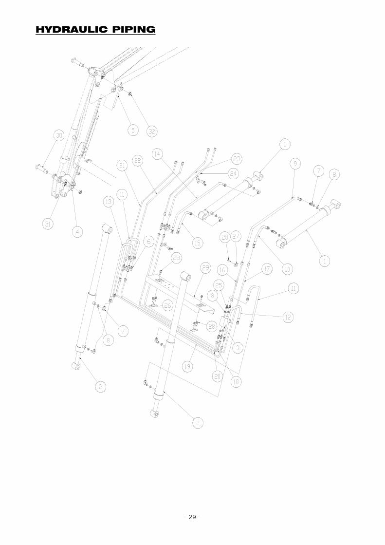
HYDRAULIC PIPING
- 29 -
HYDRAULIC PIPING
REF.NO LS PART.NO PART.NO DESCRIPTION QTY I.C SERIAL OR DATE
1 40228667 225603 BOOM CYLINDER ASSY 2
2 40286948 22A204 BUCKET CYLINDER ASSY, Ø35xØ65x1110L (ST360) 2
3 40228705 801T1-50000 VAVLE, RELIFE 1
4 40286944 FTE33-70100 BAR, GUAGE-LONG, Ø12-1375L 1
5 40286945 FT414-70200 BAR, GUAGE-SHORT, Ø17.3-2.3T-1110L 1
6 40230663 802H1-F94F9-40 NIPPLE, H-TYPE 3/4-16UNF, HOSE 4
7 40228714 802L2-P46F9-42 NIPPLE, PF3/8, O-RINGx3/4-16UNF, HOSE 90˚ 8
8 40228756 81301-BP014 O-RING, 1BP14 12
9 40228739 80620-03007 HOSE ASSY, 2(3/4-16UNF)-4(3/4-16UNF) 1000L(3/8 1
10 40228740 80620-03011 HOSE ASSY, 4(3/4-16UNF)-2(3/4-16UNF) 450L(3/8) 1
11 40228735 80620-01024 HOSE ASSY, 4(3/4-16UNF)-4(3/4-16UNF) 700L(3/8) 2
12 40228743 80620-03023 HOSE ASSY, 4(3/4-16UNF)-2(3/4-16UNF) 800L(3/8) 1
13 40228734 80620-01016 HOSE ASSY, 4(3/4-16UNF)-4(3/4-16UNF) 800(3/8) 1
14 40228737 80620-01046 HOSE ASSY, 2(3/4-16UNF)-4(3/4-16UNF) 1000L(3/8 1
15 40228736 80620-01027 HOSE ASSY, 4(3/4-16UNF)-4(3/4-16UNF) 450L(3/8) 1
16 40228803 FTF38-HP130 PIPE ASS'Y 1
17 40248399 FTF38-HP240 PIPE ASS'Y 1
18 40248400 FTF38-HP340 PIPE ASS'Y 1
19 40272713 FTF38-HP440 Pipe Ass'y 1
20 40272714 FTF38-HP540 PIPE ASS'Y 1
21 40272715 FTF38-HP640 PIPE ASS'Y 1
22 40272716 FTF38-HP740 PIPE ASS'Y 1
23 40248803 FTF38-HP840 PIPE ASS'Y 1
24 40248804 FTF38-HP940 PIPE ASS'Y 1
25 40228717 802N2-P46F9-42 NIPPLE, PF3/8,O-RINGx3/4-16UNF 4
26 40228840 LTL26-81801 CLAMP 4
27 40228841 LTL26-81802 CLAMP 1
28 40228612 1012S-M0803-35 BOLT-SEM'S, M8-1.25P 35L 11
29 40272717 LTS19-17801-03 COVER, PIPE 1
30 40230616 14124-25138-N PIN, Ø25-138L 2
31 40282263 FT416-70103-W BUSH 2
32 40228633 1021M-M2404 NUT-SELFLOCK, M24-1.5P 2
- 30 -

QUICK ATTACHMENT / BUCKET - BOBCAT TYPE
REF.NO LS PART.NO PART.NO DESCRIPTION QTY I.C SERIAL OR DATE
- 40286964 LTS21-46000-04 QUICK ATTA. ASS'Y 1
1 40272719 LTS21-46100-02 QUICK ATTA. W.A. 1
2 40286958 LTS21-46200-03 HANDLE-LH 1
3 40286959 LTS21-46300-03 HANDLE-RH 1
4 40230849 LTS21-46401-01 PIN LINK 2
5 40230850 LTS21-46402 PLATE GUIDE 2
6 40230851 LTS21-46403 WASHER #1 2
7 40230852 LTS21-46404 WASHER #2 2
8 40230853 LTS21-46405 PIN, Ø31.5-112L 2
9 40230615 14031-10030 SPRING PIN, Ø10-30L 4
10 40230854 LTS21-46407 SPRING, I.D20x130L 2
11 40228621 10191-M1406-35 HEX. BOLT-HT, M14-2.0P 35L 2
12 40228643 10316-M1400 WASHER-SPRING, M14 2
13 40286949 FTBB6-72000 Bucket W.A.-BOBCAT(72") 1
14 40230616 14124-25138-N PIN, Ø25-138L 4
15 40228633 1021M-M2404 NUT-SELFLOCK, M24-1.5P 4
16 40229894 10121-M1004-35 HEX.BOLT, M10-1.5P 35L 2
17 40228634 1021N-M1004 NUT-SELFLOCK, M10-1.5P 2
- 31 -
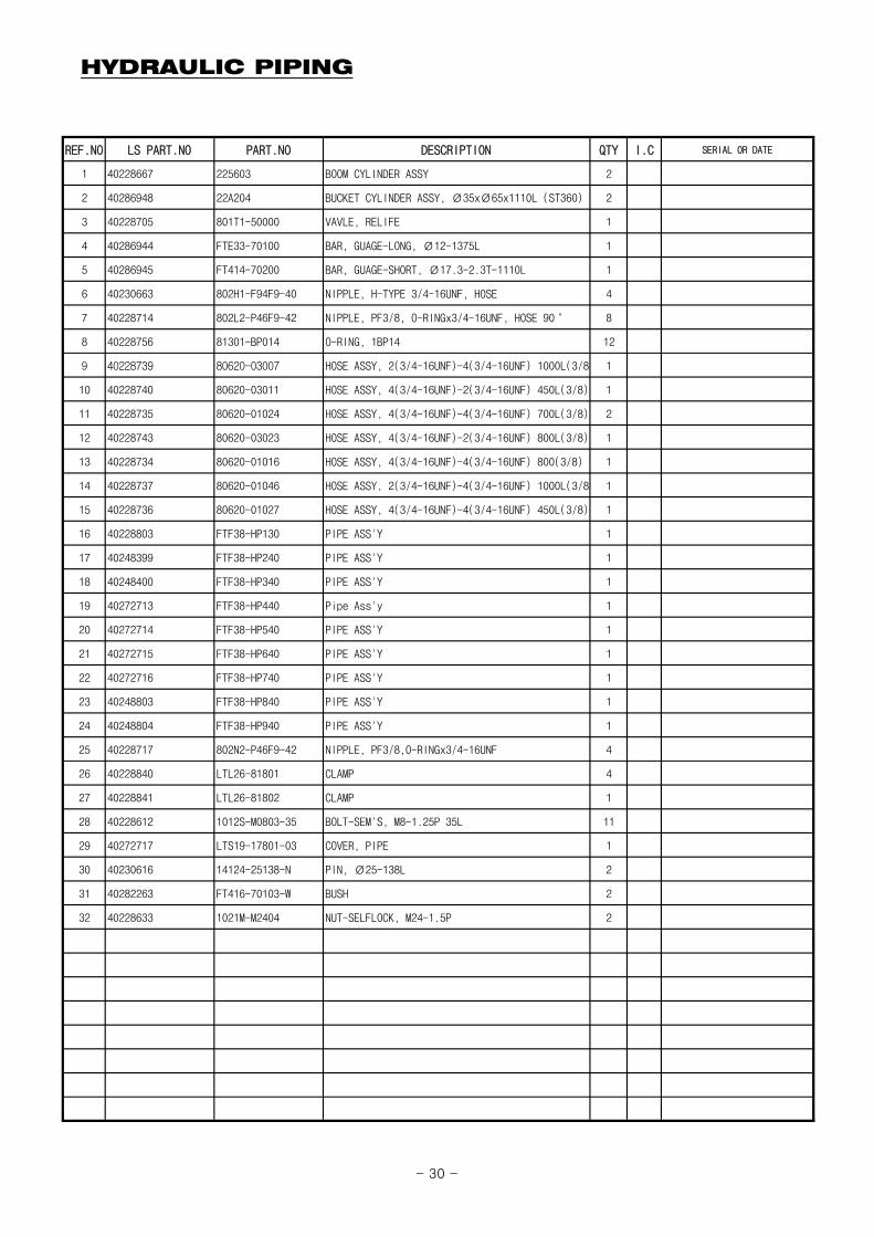
HYDRAULIC CONNECTING
REF.NO LS PART.NO PART.NO DESCRIPTION QTY I.C SERIAL OR DATE
1 40228654 103E1-C0380 SEAL BOND, 3/8" 4
2 40228716 802N2-P46F9-41 NIPPLE, PF3/8, COPPERx3/4-16UNF, HOSE 4
3 40228735 80620-01024 HOSE ASSY, 4(3/4-16UNF)-4(3/4-16UNF) 700L(3/8) 4
4 40230673 802N2-T46F9-4N NIPPLE, PT3/8x3/4-16UNF, HOSE (BULK HEAD UNION) 4
5 40228720 80410-T3360 QUICK COUPLER,MALE, PT3/8" 4
6 40228730 8044Y-03300 CAP-DUST,FEMALE, 3/8" YELLOW FEMALE 1
7 40228729 8044W-03300 CAP-DUST,FEMALE, 3/8" White Female 1
8 40228726 8044B-03300 CAP-DUST,FEMALE, 3/8" BLUE FEMALE 1
9 40228728 8044R-03300 CAP-DUST,FEMALE, 3/8" RED FEMALE 1
10 40228698 50120-M540K CABLE TIE, 540mm BLACK 3
11 40228725 8043Y-03300 CAP-DUST,MALE, 3/8" YELLOW MALE 1
12 40230676 8043W-03300 DUST CAPS, WHITE MALE 1
13 40228722 8043B-03300 CAP-DUST,MALE, 3/8" BLUE MALE 1
14 40228724 8043R-03300 CAP-DUST,MALE, 3/8" RED MALE 1
15 40228721 80420-T3360 QUICK COUPLER,FEMALE, PT3/8" 4
16 40228745 80620-04010 HOSE ASSY, 4(3/4-16UNF)-2(3/4-16UNF) 1450L(3/8) 4
17 40286969 50135-0900K WEBBING, 900L 1
18 40228697 50120-M270K CABLE TIE, 270mm BLACK 3
- 32 -

BOOM CYLINDER
REF.NO LS PART.NO PART.NO DESCRIPTION QTY I.C SERIAL OR DATE
- 40228667 225603 BOOM CYLINDER ASS'Y, Ø30x55x612L (408ST) 1
1 40228668 225603-R ROD ASS'Y 1
2 40228867 OC60-7037 CAP OUTER, Ø60x70x37L 1
3 40228827 IC60-3555 COVER INNER, Ø60x35x55L 1
4 40228766 DSSD-R035 DUST, SDR 35x43x5/6.5 1
5 40228884 UPSK-Y035 PACKING U, SKY 35x45x6 1
6 40228880 UPIS-I035 PACKING U, ISI 35x45x6 1
7 40228872 OR1B-G055 O-RING, 1BG55 2
8 40228768 DU03-5020 BUSHING DU, 35x39x20 1
9 40228876 PI60-2746 PISTON, Ø60x27x46L 1
10 40228870 OR1B-G027 O-RING, 1BG27 2
11 40228882 UPOS-I060 PACKING U, OSI 60x50x6 2
12 40228878 TRBR-0060 BACKUP RING, 60x50x3 2
13 40228886 WEWR-0060 WEARING, WR 60x55x15 1
14 40228864 NTP0-U100-C NUT, 1-14UN 1
15 40228669 225603-T TUBE ASS'Y 1
16 40228823 IA60-3555 SEAL KIT HEAD, NO.3~8 1
17 40228874 PA60-2746 SEAL KIT POSTON, NO.9~13 1
- 33 -
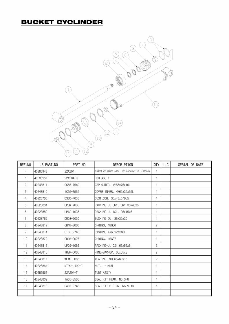
BUCKET CYCLINDER
REF.NO LS PART.NO PART.NO DESCRIPTION QTY I.C SERIAL OR DATE
- 40286948 22A204 BUCKET CYLINDER ASSY, Ø35xØ65x1110L (ST360) 1
1 40286967 22A204-R ROD ASS'Y 1
2 40248811 OC65-7540 CAP OUTER, Ø65x75x40L 1
3 40248810 IC65-3565 COVER INNER, Ø65x35x65L 1
4 40228766 DSSD-R035 DUST,SDR, 35x43x5/6.5 1
5 40228884 UPSK-Y035 PACKING U, SKY, SKY 35x45x6 1
6 40228880 UPIS-I035 PACKING U, ISI, 35x45x6 1
7 40228769 DU03-5030 BUSHING DU, 35x39x30 1
8 40248812 OR1B-G060 O-RING, 1BG60 2
9 40248814 PI65-2746 PISTON, Ø65x27x46L 1
10 40228870 OR1B-G027 O-RING, 1BG27 1
11 40248816 UPOS-I065 PACKING-U, OSI 65x55x6 2
12 40248815 TRBR-0065 RING-BACKUP, 65x55x3 2
13 40248817 WEWR-0065 WEARING, WR 65x60x15 2
14 40228864 NTP0-U100-C NUT, 1-14UN 1
15 40286968 22A204-T TUBE ASS'Y 1
16 40248809 IA65-3565 SEAL KIT HEAD, No.3~8 1
17 40248813 PA65-2746 SEAL KIT PISTON, No.9~13 1
- 34 -

DECALS
CAUTION :
Refer to category "Safety decals"
Read and refer to the Tractor Operation Manual or Decals on the Tractor. and Loader Decals on as shown.
⑥④ ⑤
⑦
①
③
②
- 35 -

DECALS
REF.NO LS PART.NO PART.NO DESCRIPTION QTY I.C SERIAL OR DATE
1 40286951 3103E-00013 DECAL, SAFETY LOCK 2
2 40230653 3104E-00010 NAME PLATE 1
3 40286955 3101E-00433 DECAL,MODEL-LL5103(LH) 1
4 40286953 3102E-00002 DECAL, WARNING 1
5 40286954 3102E-00003 DECAL, WARNING 1
6 40286956 3101E-00434 DECAL,MODEL-LL5103(RH) 1
7 40286952 3102E-00001 DECAL, WARNING 1
- 36 -
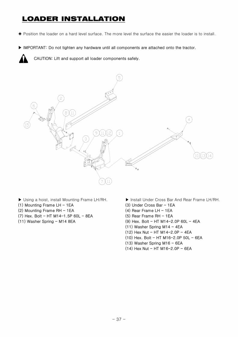
LOADER INSTALLATION
▶ IMPORTANT: Do not tighten any hardware until all components are attached onto the tractor.
CAUTION: Lift and support all loader components safely.
▶ Using a hoist, install Mounting Frame LH/RH. ▶ Install Under Cross Bar And Rear Frame LH/RH.
(1) Mounting Frame LH - 1EA (3) Under Cross Bar - 1EA
(2) Mounting Frame RH - 1EA (4) Rear Frame LH - 1EA
(7) Hex. Bolt - HT M14-1.5P 60L - 8EA (5) Rear Frame RH - 1EA
(11) Washer Spring - M14 8EA (9) Hex. Bolt - HT M14-2.0P 60L - 4EA
(11) Washer Spring M14 - 4EA
(12) Hex Nut - HT M14-2.0P - 4EA
(10) Hex. Bolt - HT M16-2.0P 50L - 6EA
(13) Washer Spring M16 - 6EA
(14) Hex Nut - HT M16-2.0P - 6EA
◈ Position the loader on a hard level surface. The more level the surface the easier the loader is to install.
- 37 -

LOADER INSTALLATION
▶ Install Grille Guard ▶ Install Bracket, Hose
(10) Grille W.A. - 1EA (6) Bracket, Hose - 1EA
(17) Hex. Bolt - HT M14-1.5P 50L - 4EA (15) Bolt-Sem's, M8-1.25P 35L - 2EA
(18) Washer Spring M14 - 4EA
Verify that all mounting kit hardware has been torqued as specified before installing loader.
▶ Identify hardware size and grade.
▶ Refer to Torque Chart, page 24 and find correct torque for your hardware size and grade.
▶ Torque hardware to this specification unless otherwise specfied.
▶ IMPORTANT NOTE: To keep mounting kit hardware from loosening during loader operation, hardware must be torque to specifications.
- 38 -

LOADER INSTALLATION
▶ Install Boom Ass'y.Hang the groove on the pin located on Mounting Frame.
Loader
Mounting Frame
Post
- 39 -