Embed Size (px)
DESCRIPTION
Presentation Engine of LS600hL
Citation preview

Body Electrical
Model Outline Hybrid System Engine Chassisfor Technician
Engine OverallOutline– V8 (90-degree), 5.0-liter, 32-valve, D-4S engine w/Dual
VVT-i (VVT-iE for Intake), ETCS-i and ACIS
-A -W

Body Electrical
Model Outline Hybrid System Engine Chassisfor Technician
Engine OverallFeatures
-A -W
Engine Coolant Distribution
Pathway
Separator Case for PCV
2 High-Pressure Fuel Pumps
Double Slit-nozzle Injector
D-4S
Water Jacket Spacer
4 Flat Type Knock Sensors
•Dual VVT-i •VVT-iE for Intake
Delivery Pipe with Pulsation
Damper Function
MRE Type VVT Sensor

Body Electrical
Model Outline Hybrid System Engine Chassisfor Technician
Engine OverallFeatures
-A -W
Element Replacement Type Oil Filter
4 Timing Chains
DC Motor for ACIS Valve
Long-reach Type Spark
Plug
Magnesium Made Head
Cover
Spiny Liner
Hydraulic Lash Adjuster

Body Electrical
Model Outline Hybrid System Engine Chassisfor Technician
Engine OverallSpecifications
-A -W
LS600hL / LS600h LS460L / LS460
Engine Type 2UR-FSE 1UR-FSE 1UR-FE
No. of Cyls & Arrangement 8-cylinder, V- type
Valve Mechanism32-valve DOHC, Chain Drive Dual VVT-i (VVT-iE)
Displacement [cm3 (cu. in.)]
4,969 (303.2)
4,608 (281.2)
Bore x Stroke [mm (in.)]
94.0 x 89.5 (3.70 x 3.52)
94.0 x 83.0 (3.70 x 3.27)
Compression Ratio 11.8 10.8
Max. Output[kW (HP) @ rpm]
-A290 (389) @ 6,400
283 (380) @ 6,400 —
-W 280 @ 6,400 255 @ 6,400
Max. Torque[Nm (ftlbf) @ rpm]
-A 521 (385) @ 4,000 498 (367) @ 4,100 —
-W 520 @ 4,000 493 @ 4,100 455 @ 4,000

Body Electrical
Model Outline Hybrid System Engine Chassisfor Technician
Engine OverallSpecifications
-A -W
LS600hL / LS600h LS460L / LS460
Engine Type 2UR-FSE 1UR-FSE 1UR-FE
Valve Timing[deg]
Cylinder No. #4,5,7,8 #1,2,3,6 #4,5,7,8 #1,2,3,6 #4,5,7,8 #1,2,3,6
IntakeOpen (BTDC) –33 to 22 –29 to 26 –14 to 26 –10 to 30
Close (ABDC) 101 to 46 97 to 42 82 to 42 78 to 38
ExhaustOpen (BBDC) 60 to 25 64 to 29 60 to 28 64 to 32
Close (ATDC) 4 to 39 0 to 35 4 to 36 0 to 32
Firing Order1 – 8 – 7 – 3 – 6 – 5 – 4 – 2
Emission Regulation
N.A. (CARB)
Tailpipe LEVII-SULEV, SFTP LEVII-ULEV, SFTP —
Evaporative
LEVII, ORVR —
Europe EURO IV —
Except Europe *1 EURO IV, EURO III or EURO II
EURO III, EURO II or Tier1
Engine Service Mass *2
[kg (lb)]236 (520) 232 (511) 225 (496)
*1: The emission regulation differs depending on the country or region.*2: Weight shows the figure with the engine oil and engine coolant fully filled.

Body Electrical
Model Outline Hybrid System Engine Chassisfor Technician
Engine OverallMajor Difference from 1UR-FSE
-A -W
LS600hL / LS600h LS460L / LS460
Engine Type 2UR-FSE 1UR-FSE
Crankshaft Pulley Without balance piece With balance piece
VVT-iE Operation Range 55 ºCA 40 ºCA
Delivery Pipe (Direct) With electric relief valve With mechanical relief valve
[-A only]
TWCHCAC System
(Hydro-Carbon Adsorber and Catalyst system)
Conventional
Evaporative Emission Control
System
Closed fuel tank system(with key-off monitor)
Key-off monitor

Body Electrical
Model Outline Hybrid System Engine Chassisfor Technician
Fuel SystemDelivery Pipe (Direct)– Electric relief valve
-A -W
From Delivery
Pipe
To Return Pipe
Same as 2GR-FSE on GS450h

Body Electrical
Model Outline Hybrid System Engine Chassisfor Technician
HCAC SystemGeneral– The HCAC system adsorbs the hydrocarbons emitted
during a cold start contained in exhaust gas
-A
From HCAC VSV
HCAC Valve
HC Adsorver
TWC
Actuator
HC Adsorber and Catalyst (RH)

Body Electrical
Model Outline Hybrid System Engine Chassisfor Technician
HCAC SystemSystem Diagram
-A
ECM
Mass Air Flow Meter HCAC VSV
Engine Coolant Temperature Sensor
Exhaust Gas Temperature
Sensors
HCAC ValveActuator

Body Electrical
Model Outline Hybrid System Engine Chassisfor Technician
HCAC SystemParts Location
-A
HCAC VSV
Exhaust Gas Temperature Sensor (x4)
ActuatorHC Adsorber and Catalyst

Body Electrical
Model Outline Hybrid System Engine Chassisfor Technician
HCAC SystemOperation (After the Cold Start)– HCAC valve is closed
• Exhaust gas flows into the HC adsorber and the hydrocarbons in exhaust gas are adsorbed
-A
Closed
Adsorbing HC
TWC Temp. is Low
Vacuum

Body Electrical
Model Outline Hybrid System Engine Chassisfor Technician
HCAC SystemOperation (After the TWC has Warmed Up)– HCAC valve is opened
• Hydrocarbons stored in the HC adsorber flow into the TWC with a main flow
-A
Opened
Removing HC

Body Electrical
Model Outline Hybrid System Engine Chassisfor Technician
HCAC SystemOperation (After the Engine has Warmed Up)– HCAC valve is closed (for a few seconds)
• The remaining hydrocarbons in HC adsorber are completely removed
-A
Closed
Completely Removing HC
Vacuum

Body Electrical
Model Outline Hybrid System Engine Chassisfor Technician
HCAC SystemExhaust Gas Temperature Sensor– Measures exhaust gas temperatures to monitor the
open or close status of the HCAC valve
-A
Front Sensor Rear Sensor
Temperature Rise
Front > Rear
Temperature Rise
Front < Rear
Front Sensor Rear Sensor
Closed
Opened

Body Electrical
Model Outline Hybrid System Engine Chassisfor Technician
HCAC SystemDTCs for HCAC System
-A
DTC Detection Item
P0545 Exhaust Gas Temperature Sensor Circuit Low (Bank 1 Sensor 1)
P0546 Exhaust Gas Temperature Sensor Circuit High (Bank 1 Sensor 1)
P0548 Exhaust Gas Temperature Sensor Circuit Low (Bank 2 Sensor 1)
P0549 Exhaust Gas Temperature Sensor Circuit High (Bank 2 Sensor 1)
P1081 HC Adsorber Switching Valve Bank 1 Stuck Open
P1082 HC Adsorber Switching Valve Bank 1 Stuck Close
P1083 HC Adsorber Switching Valve Bank 2 Stuck Open
P1084 HC Adsorber Switching Valve Bank 2 Stuck Close
P1438 HCAC System Variable Valve (HCAC VSV) Circuit Low
P2032 Exhaust Gas Temperature Sensor Circuit Low (Bank 1 Sensor 2)
P2033 Exhaust Gas Temperature Sensor Circuit High (Bank 1 Sensor 2)
P2035 Exhaust Gas Temperature Sensor Circuit Low (Bank 2 Sensor 2)
P2036 Exhaust Gas Temperature Sensor Circuit High (Bank 2 Sensor 2)
Body Electrical
Model Outline Hybrid System Engine Chassisfor Technician
Engine Control SystemVVT-iE– VVT-iE (Motor Drive) for intake valve– Hydraulic (conventional) VVT-i for exhaust valve
ExhaustExhaust
IntakeIntake
Hydraulic
Motor-drive
-A -WSame as 1UR-FSE on LS460L

Body Electrical
Model Outline Hybrid System Engine Chassisfor Technician
Engine Control SystemVVT-iE– Parts location of VVT system
Camshaft Position Sensor
OCV For Exhaust
VVT Sensor(EX, RH)
VVT Sensor(EX, LH)
VVT Sensor(IN, LH)
VVT Sensor(IN, RH)
Crankshaft Position Sensor
VVT-i ControllerFor Exhaust
•Camshaft Control Motor•Reduction mechanism•Link Mechanism
VVT-iE ControllerFor Intake
-A -W

Body Electrical
Model Outline Hybrid System Engine Chassisfor Technician
Engine Control SystemVVT-iE– Operation range is expanded by changing from
hydraulic type to motor-drive type
Engine Speed
THW
Hydraulic VVT-i
VVT-iEVVT-iE
VVT System Operation Range
Low High
High
Low
-A -W

Body Electrical
Model Outline Hybrid System Engine Chassisfor Technician
Engine Control SystemVVT-iE– System Diagram
Engine ECU
(ECM)
Crankshaft Position Sensor
Camshaft Control Motor Assembly
Camshaft Position Sensor
EDUMotor
Rotation Angle Sensor
VVT Sensor
-A -W

Body Electrical
Model Outline Hybrid System Engine Chassisfor Technician
Engine Control SystemVVT-iE– Construction of Camshaft Control Motor and VVT-iE
controller
Cycloid Reduction Mechanism
Motor
EDULink Mechanism
Intake Camshaft
Chain Sprocket(Primary)
-A -W

Body Electrical
Model Outline Hybrid System Engine Chassisfor Technician
Engine Control SystemVVT-iE– EDU controls the motor, and feeds back the state of
the motor to engine ECU (ECM)
EDUMotor(12V)
Rotation Angle Sensor
Engine ECU
(ECM)
VTP
VTS
VTD
VTM
Motor Speed and Rotation Direction Command Signal
Actual Motor Speed
Actual Motor Rotation Direction
Fail Information
EDT1
EMR1
EMF1
EMD1
Camshaft Control Motor
-A -W
Body Electrical
Model Outline Hybrid System Engine Chassisfor Technician
EDUMotor(12V)
Rotation Angle Sensor
Engine ECU
(ECM)
VTP
VTS
VTD
Motor Speed and Rotation Direction Command Signal
Actual Motor Speed
Actual Motor Rotation Direction
EDT1
EMR1
EMF1
Camshaft Control Motor
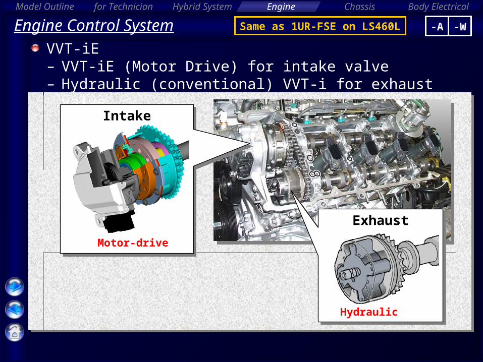
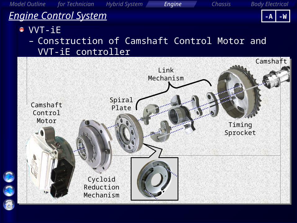
Engine Control SystemVVT-iE– Fail information from EDU
Fail Information
EMD1
ConditionDuty Ratio
Open circuit between VTP and EDT1 100 %
Normal 80 %
EDU Overheat, Motor voltage malfunction
60 %
Rotation angle sensor malfunction 40 %
Protection mode for the motor over current
20 %
VTM5V
-A -W
Body Electrical
Model Outline Hybrid System Engine Chassisfor Technician
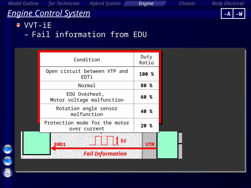
Engine Control SystemVVT-iE– Construction of Camshaft Control Motor and VVT-iE
controller
Camshaft Control Motor
Camshaft
Cycloid Reduction
Mechanism
Link Mechanism
Timing Sprocket
Spiral Plate
-A -W

Body Electrical
Model Outline Hybrid System Engine Chassisfor Technician
Engine Control SystemVVT-iE– Construction of cycloid reduction mechanism
Planetary Gear [Output]
Carrier[Input]
Sun Gear(Housing Cover)
Bearing

Body Electrical
Model Outline Hybrid System Engine Chassisfor Technician
Engine Control SystemVVT-iE– Operation of cycloid reduction mechanism
Reduction Ratio: 26Reduction Ratio: 26 [ ]: Number of teeth
Motor shaft turns 1
Planetary Gear [27]
Sun Gear [26](Housing Cover)
Planetary gear turns 1/26
-A -W

Body Electrical
Model Outline Hybrid System Engine Chassisfor Technician
Engine Control SystemVVT-iE– Operation (Outline)
The difference between the camshaft speed and motor speed is VVT operation
Rotational Speed
Motor Speed
Camshaft Speed
Valve Timing
Advance
Retard
Fast
Slow
VVT Mode RetardAdvance Hold HoldHold
-A -W

Body Electrical
Model Outline Hybrid System Engine Chassisfor Technician
Engine Control SystemVVT-iE– Advance operation (Motor Speed > Camshaft Speed)
Advance
Connected to timing sprocket
Connected to camshaft
Spiral plate rotates by
motor
Link Control
Pin
-A -W

Body Electrical
Model Outline Hybrid System Engine Chassisfor Technician
Engine Control SystemVVT-iE– Retard operation (Motor Speed < Camshaft Speed)
Retard
Connected to timing sprocket
Connected to camshaft
Spiral plate rotates by
motor
Link Control
Pin
-A -W

Body Electrical
Model Outline Hybrid System Engine Chassisfor Technician
Engine Control SystemVVT-iE– Hold operation (Motor Speed = Camshaft Speed)
Connected to timing sprocket
Connected to camshaft
Spiral plate does not
rotate
-A -W

Body Electrical
Model Outline Hybrid System Engine Chassisfor Technician
Engine Control SystemVVT-iE– Operation
XVL Player
Click the green sphereClick!
-A -W

Body Electrical
Model Outline Hybrid System Engine Chassisfor Technician
Engine Control SystemVVT-iE– System operation
[During Idling]
TDC
BDC
Reduce blow back to the intake side
- Effect -•Stabilized idling rpm •Better fuel economy
[In Low Speed Range with Light to Medium Load]
TDC
BDC
Increase internal EGR,
Eliminate pumping loss
- Effect -•Better fuel economy•Improved emission control
Middle Retard
Retard
-A -W
MostAdvanced

Body Electrical
Model Outline Hybrid System Engine Chassisfor Technician
Engine Control SystemVVT-iE– System operation[In Low to Medium Speed Range with Heavy Load]
Volumetric efficiency
improvement
- Effect -•Improved torque in low to medium speed range
[In High Speed Range with Heavy Load]
- Effect -•Improved output
TDC
BDC
Advanced
TDC
BDC
Advanced
Advanced Volumetric efficiency
improvement
Retard
-A -W

Body Electrical
Model Outline Hybrid System Engine Chassisfor Technician
Engine Control SystemVVT-iE– System operation
[At Low Temperatures]
TDC
BDC
Reduce blow back to the intake side,
stabilizes the idling speed at fast idle
- Effect -•Stabilized fast idling rpm •Better fuel economy
[Upon Starting / Stopping the Engine]
TDC
BDC
Control to optimal timing for engine start
- Effect -•Improved startability
MostRetarded
-A -W
Retard
MostAdvanced
MostAdvanced

Body Electrical
Model Outline Hybrid System Engine Chassisfor Technician
Engine Control SystemVVT-iE– DTC for VVT-iE (1/2)
DTC Detection Item Trouble Area
P0010Camshaft Position "A" Actuator Circuit (Bank 1)
• Camshaft timing control motor (bank 1)• Camshaft timing gear assembly (bank 1)
P0011Camshaft Position "A" – Timing Over-Advanced or System Performance (Bank 1)
• Camshaft timing gear assembly (bank 1)
P0012Camshaft Position "A" – Timing Over-Retarded (Bank 1)
• Camshaft timing gear assembly (bank 1)• Camshaft timing control motor (bank 1)
P0016Crankshaft Position – Camshaft Position Correlation (Bank 1 Sensor A)
• Valve timing• Camshaft timing gear assembly (bank 1)• Camshaft timing control motor (bank 1)
P0018Crankshaft Position – Camshaft Position Correlation (Bank 2 Sensor A)
• Valve timing• Camshaft timing gear assembly (bank 2)• Camshaft timing control motor (bank 2)
P0020Camshaft Position "A" Actuator Circuit (Bank 2)
• Camshaft timing control motor (bank 2)• Camshaft timing gear assembly (bank 2)
P0021Camshaft Position "A" – Timing Over-Advanced or System Performance (Bank 2)
• Camshaft timing gear assembly (bank 2)
P0022Camshaft Position "A" – Timing Over-Retarded (Bank 2)
• Camshaft timing gear assembly (bank 2)• Camshaft timing control motor (bank 2)
P1023Camshaft Position Signal Output "B" Circuit
• Camshaft timing control motor (bank 1)
-A -W

Body Electrical
Model Outline Hybrid System Engine Chassisfor Technician
Engine Control SystemVVT-iE– DTC for VVT-iE (2/2)
DTC Detection Item Trouble Area
P1360"A" Camshaft Position Actuator Circuit Open, Low, High Bank1
• Camshaft timing control motor (bank 1)• Wire harness and connector
P1361"A" Camshaft Position Actuator Circuit Open, Low, High Bank2
• Camshaft timing control motor (bank 2)• Wire harness and connector
P1362"B" Camshaft Position Actuator Circuit Open, Low, High Bank1
• Camshaft timing control motor (bank 1)• Wire harness and connector
P1363"B" Camshaft Position Actuator Circuit Open, Low, High Bank2
• Camshaft timing control motor (bank 2)• Wire harness and connector
P1364"C" Camshaft Position Actuator Circuit Open, Low, High Bank1
• Camshaft timing control motor (bank 1)• Power supply of Camshaft timing control• motor (bank 1)• Wire harness and connector
P1365"C" Camshaft Position Actuator Circuit Open, Low, High Bank2
• Camshaft timing control motor (bank 2)• Power supply of camshaft timing control• motor (bank 2)• Wire harness and connector
P1366"E" Camshaft Position Actuator Circuit Open, Low, High Bank1
• Camshaft timing control motor (bank 1)• Wire harness and connector
P1367"E" Camshaft Position Actuator Circuit Open, Low, High Bank2
• Camshaft timing control motor (bank 2)• Wire harness and connector
P2614Camshaft Position Signal Output Circuit / Open
• Camshaft timing control motor (bank 2)
-A -W

Body Electrical
Model Outline Hybrid System Engine Chassisfor Technician
Engine Control SystemVVT-iE– Fail-safe
DTC Component Fail-Safe OperationFail Safe
Deactivation Condition
P0010, P0020, P1023, P1360, P1361, P1362, P1363, P1364, P1365, P1366, P1367, P2614
Camshaft timing control motor
• Idling up (fire prevention), or power to camshaft timing control motor is cut• Valve timing of bank that is operating normally is fixed at maximum retard angle
Pass condition detected
– Active TestTester Display Test Part Control Range
MD VVT B1 VVT-iE (bank1)0 to 40º
MD VVT B2 VVT-iE (bank2)
-A -W