Embed Size (px)
Citation preview
LSI SAS 3041E Serial Attached SCSI RAIDHost Bus Adapter installation
IntroductionThis document describes how to install an LSI SAS 3041E Serial Attached SCSI (SAS) Redundant Arrayof Independent Disks (RAID) Host Bus Adapter (HBA) in HP and xw Workstation series. Proceduresare included for hard drives mounted in hard drive bays and optical drive bays.
Kit contents● LSI SAS 3041E SAS RAID HBA (RAID controller card)
● SAS driver CD
● Hard drive activity LED cables
● Installation instructions (this document)
● Warranty information
Before you beginTo view QuickSpecs and determine the compatibility of this product with your HP workstation, seehttp://www.hp.com/go/productbulletin.
© 2006–2009 Hewlett-Packard Development Company, L.P. Printed in the U.S.
ENWW Introduction 1
Warnings and cautionsWARNING! Any surface or area of the equipment marked with this symbol indicates the presenceof an electrical shock hazard. To reduce the risk of injury from electrical shock, do not open any enclosedarea marked with this symbol.
WARNING! To reduce the risk of electric shock or damage to your equipment:
— Do not disable the power cord grounding plug. The grounding plug is an important safety feature.
— Plug the power cord in a grounded (earthed) outlet that is easily accessible at all times.
— Disconnect power from the equipment by unplugging the power cord from the electrical outlet.
WARNING! Any surface or area of the equipment marked with this symbol indicates the presenceof a hot surface or hot component. If this surface is contacted, the potential for injury exists. To reducethe risk of injury from a hot component, enable the surface to cool before touching.
WARNING! If a product is shipped in packaging marked with this symbol, , the product must always
be lifted by two persons to avoid personal injury due to product weight.
WARNING! To reduce the risk of serious injury, read the Safety & Comfort Guide. It describes properworkstation setup, posture, health, and work habits for computer users, and provides important electricaland mechanical safety information. This guide is located at http://www.hp.com/ergo and on thedocumentation CD (if one is included with the product).
CAUTION: Static electricity can damage the electronic components of the workstation. Beforebeginning these procedures, be sure you discharge static electricity by briefly touching a grounded metalobject.
CAUTION: To prevent damage to the workstation, observe the following Electrostatic Discharge(ESD) precautions while performing the system parts removal and replacement procedures:
— Work on a static-free mat.
— Wear a static strap to ensure that any accumulated electrostatic charge is discharged from your bodyto the ground.
— Create a common ground for the equipment you are working on by connecting the static-free mat,static strap, and peripheral units to that piece of equipment.
NOTE: HP accessories are for use in HP Workstation products. They have been extensively testedfor reliability and are manufactured to high quality standards.
2 LSI SAS 3041E Serial Attached SCSI RAID Host Bus Adapter installation ENWW
Step 1—Preparing for component installationNOTE: Workstation models vary. All illustrations are examples only.
Download and install updates1. Check for available system BIOS updates specified for your HP workstation model and operating
system at http://www.hp.com/go/workstationsupport.
2. Install the system BIOS updates, if available.
Accessing the internal components of the workstation1. If you need help preparing the workstation for this installation, consult the removal and replacement
procedures in the service guide for your workstation at http://www.hp.com/support/workstation_manuals.
NOTE: For the HP Workstation series, these procedures are also available in the UserGuide on the Documentation and Diagnostics CD that shipped with your workstation.
2. Power down the workstation, and then disconnect the power cord.
3. Power down all external devices, and then disconnect them from the workstation.
4. Remove the side access panel.
Removing components1. If present, remove the card support to enable access to the expansion slots and system board
connectors.
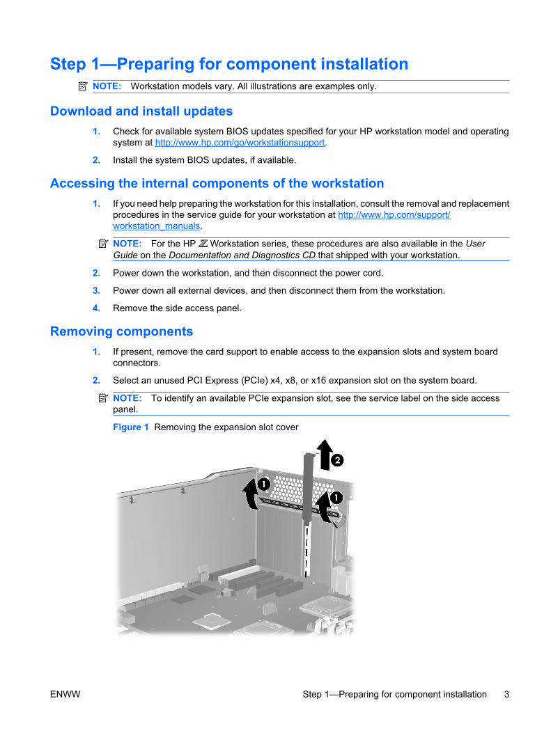
2. Select an unused PCI Express (PCIe) x4, x8, or x16 expansion slot on the system board.
NOTE: To identify an available PCIe expansion slot, see the service label on the side accesspanel.
Figure 1 Removing the expansion slot cover
ENWW Step 1—Preparing for component installation 3
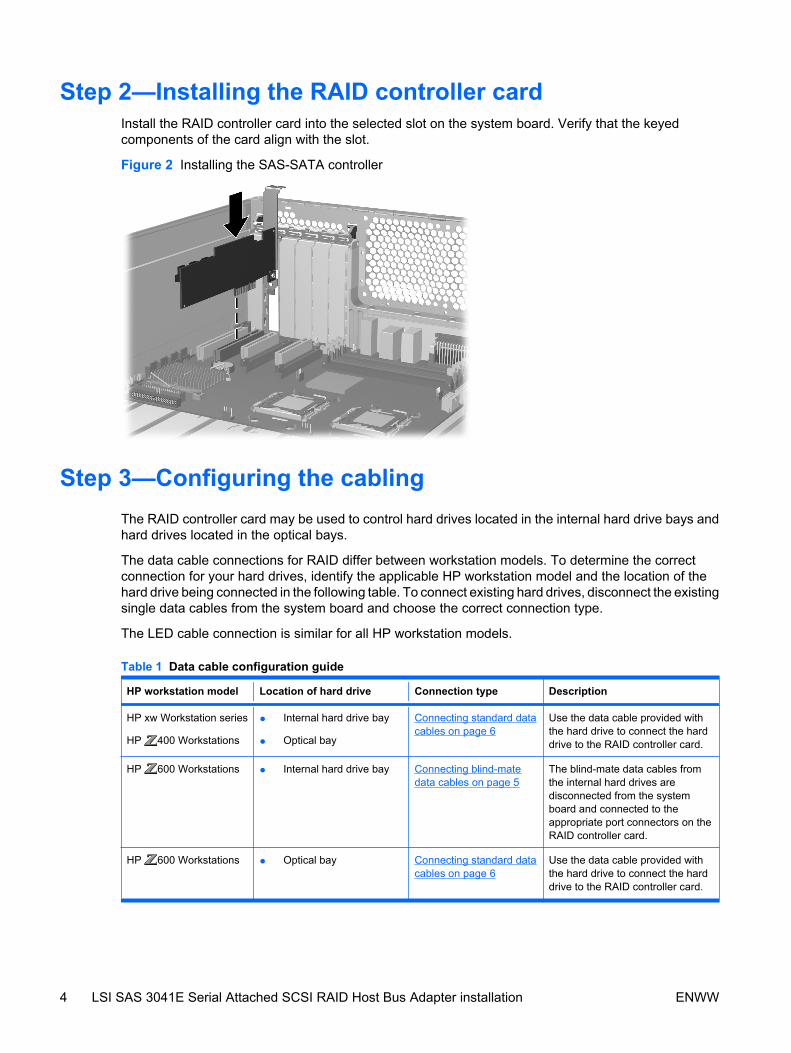
Step 2—Installing the RAID controller cardInstall the RAID controller card into the selected slot on the system board. Verify that the keyedcomponents of the card align with the slot.
Figure 2 Installing the SAS-SATA controller
Step 3—Configuring the cablingThe RAID controller card may be used to control hard drives located in the internal hard drive bays andhard drives located in the optical bays.
The data cable connections for RAID differ between workstation models. To determine the correctconnection for your hard drives, identify the applicable HP workstation model and the location of thehard drive being connected in the following table. To connect existing hard drives, disconnect the existingsingle data cables from the system board and choose the correct connection type.
The LED cable connection is similar for all HP workstation models.
Table 1 Data cable configuration guide
HP workstation model Location of hard drive Connection type Description
HP xw Workstation series
HP 400 Workstations
● Internal hard drive bay
● Optical bay
Connecting standard datacables on page 6
Use the data cable provided withthe hard drive to connect the harddrive to the RAID controller card.
HP 600 Workstations ● Internal hard drive bay Connecting blind-matedata cables on page 5
The blind-mate data cables fromthe internal hard drives aredisconnected from the systemboard and connected to theappropriate port connectors on theRAID controller card.
HP 600 Workstations ● Optical bay Connecting standard datacables on page 6
Use the data cable provided withthe hard drive to connect the harddrive to the RAID controller card.
4 LSI SAS 3041E Serial Attached SCSI RAID Host Bus Adapter installation ENWW
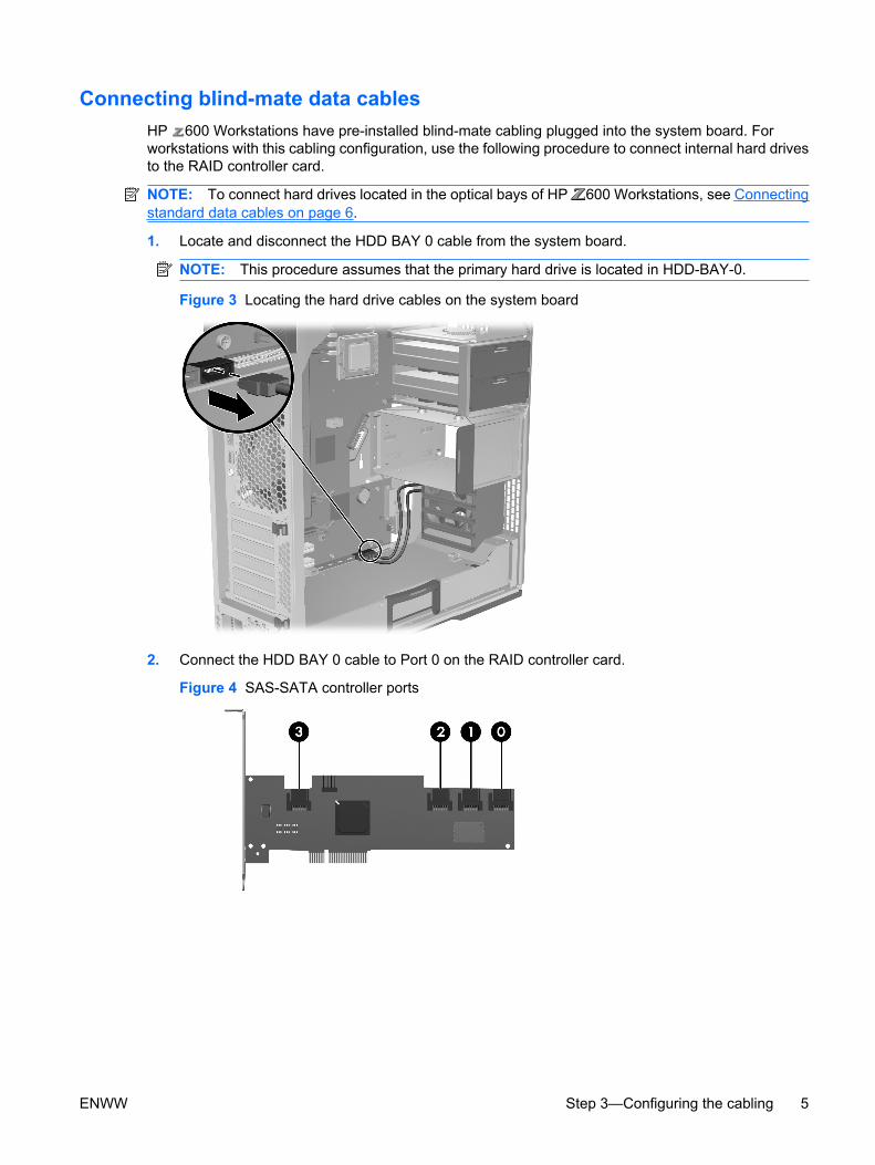
Connecting blind-mate data cablesHP 600 Workstations have pre-installed blind-mate cabling plugged into the system board. Forworkstations with this cabling configuration, use the following procedure to connect internal hard drivesto the RAID controller card.
NOTE: To connect hard drives located in the optical bays of HP 600 Workstations, see Connectingstandard data cables on page 6.
1. Locate and disconnect the HDD BAY 0 cable from the system board.
NOTE: This procedure assumes that the primary hard drive is located in HDD-BAY-0.
Figure 3 Locating the hard drive cables on the system board
2. Connect the HDD BAY 0 cable to Port 0 on the RAID controller card.
Figure 4 SAS-SATA controller ports
ENWW Step 3—Configuring the cabling 5
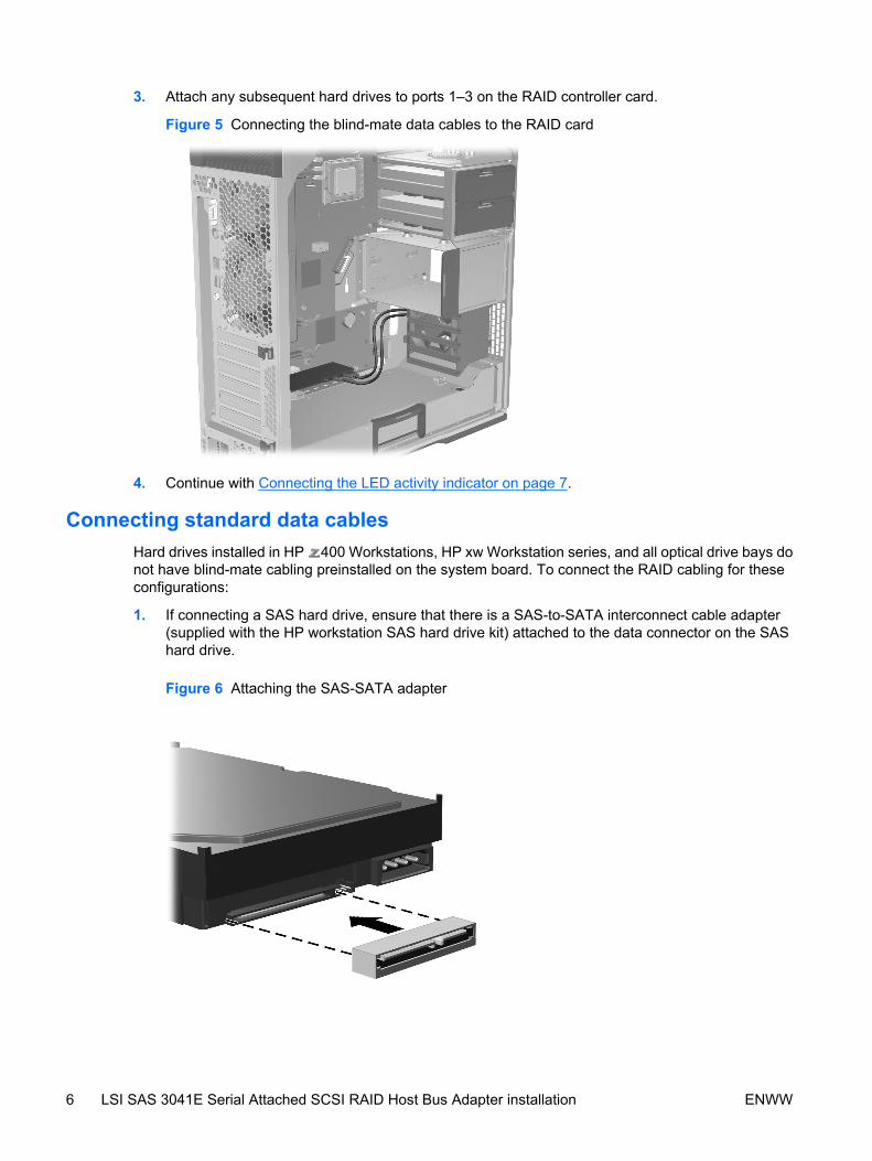
3. Attach any subsequent hard drives to ports 1–3 on the RAID controller card.
Figure 5 Connecting the blind-mate data cables to the RAID card
4. Continue with Connecting the LED activity indicator on page 7.
Connecting standard data cablesHard drives installed in HP 400 Workstations, HP xw Workstation series, and all optical drive bays donot have blind-mate cabling preinstalled on the system board. To connect the RAID cabling for theseconfigurations:
1. If connecting a SAS hard drive, ensure that there is a SAS-to-SATA interconnect cable adapter(supplied with the HP workstation SAS hard drive kit) attached to the data connector on the SAShard drive.
Figure 6 Attaching the SAS-SATA adapter
6 LSI SAS 3041E Serial Attached SCSI RAID Host Bus Adapter installation ENWW
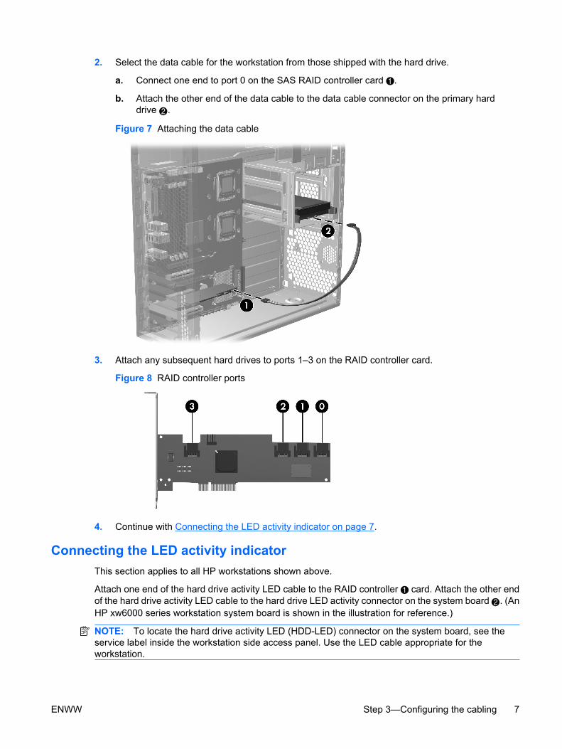
2. Select the data cable for the workstation from those shipped with the hard drive.
a. Connect one end to port 0 on the SAS RAID controller card .
b. Attach the other end of the data cable to the data cable connector on the primary harddrive 2.
Figure 7 Attaching the data cable
3. Attach any subsequent hard drives to ports 1–3 on the RAID controller card.
Figure 8 RAID controller ports
4. Continue with Connecting the LED activity indicator on page 7.
Connecting the LED activity indicatorThis section applies to all HP workstations shown above.
Attach one end of the hard drive activity LED cable to the RAID controller card. Attach the other endof the hard drive activity LED cable to the hard drive LED activity connector on the system board 2. (AnHP xw6000 series workstation system board is shown in the illustration for reference.)
NOTE: To locate the hard drive activity LED (HDD-LED) connector on the system board, see theservice label inside the workstation side access panel. Use the LED cable appropriate for theworkstation.
ENWW Step 3—Configuring the cabling 7
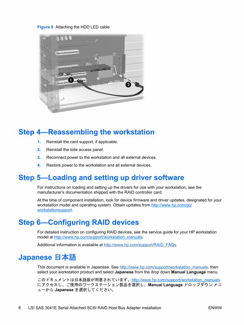
Figure 9 Attaching the HDD LED cable
Step 4—Reassembling the workstation1. Reinstall the card support, if applicable.
2. Reinstall the side access panel.
3. Reconnect power to the workstation and all external devices.
4. Restore power to the workstation and all external devices.
Step 5—Loading and setting up driver softwareFor instructions on loading and setting up the drivers for use with your workstation, see themanufacturer’s documentation shipped with the RAID controller card.
At the time of component installation, look for device firmware and driver updates, designated for yourworkstation model and operating system. Obtain updates from http://www.hp.com/go/workstationsupport.
Step 6—Configuring RAID devicesFor detailed instruction on configuring RAID devices, see the service guide for your HP workstationmodel at http://www.hp.com/support/workstation_manuals.
Additional information is available at http://www.hp.com/support/RAID_FAQs
Japanese 日本語This document is available in Japanese. See http://www.hp.com/support/workstation_manuals, thenselect your workstation product and select Japanese from the drop down Manual Language menu.
このドキュメントは日本語版が用意されています。http://www.hp.com/support/workstation_manualsにアクセスし、ご使用のワークステーション製品を選択し、Manual Language ドロップダウン メニューから Japanese を選択してください。
8 LSI SAS 3041E Serial Attached SCSI RAID Host Bus Adapter installation ENWW