Embed Size (px)
Citation preview
LSI3101/3101A
Encoder / Linear Scale
Counter Card
Software Manual (V1.2)
健昇科技股份有限公司
JS AUTOMATION CORP.
新北市汐止區中興路 100號 6樓
6F., No.100, Zhongxing Rd., Xizhi Dist., New Taipei City, Taiwan
TEL:+886-2-2647-6936
FAX:+886-2-2647-6940
http://www.automation.com.tw
http://www.automation-js.com/ E-mail:[email protected]

1
Correction record
Version Record
1.0 for wdm3101 V1.0, LSI3101.dll V1.0 up
1.1 for wdm3101 V1.2, LSI3101.dll V1.2 up
add LSI3101A related functions (CIO input up to 16M)
1.2 For LSI3101.dll V2.3 up and card firmware 1.4
Add LSI3101_toggle_preset and LSI3101_CO_read.
Enhance LSI3101_compare_increment_set to 32 bit length
Enhance LSI3101_compare_FIFO_set to 32 bit length

2
Contents
1. How to install the software of LSI3101/3101A ............................................................................... 5
1.1 Install the PCI driver .............................................................................................................. 5
2. Where to find the file you need ....................................................................................................... 6
3. About the LSI3101 software ............................................................................................................ 7
3.1 What you need to get started .................................................................................................. 7
3.2 Software programming choices ............................................................................................. 7
4. LSI3101 Language support .............................................................................................................. 8
4.1 Building applications with the LSI3101 software library ...................................................... 8
4.2 LSI3101 Windows Libraries .................................................................................................. 8
5. Basic concepts of digital I/O control ............................................................................................... 9
5.1 Types of I/O classified by isolation ....................................................................................... 9
5.2 Types of Output classified by driver device .......................................................................... 9
5.3 Input debounce ..................................................................................................................... 10
5.4 Input interrupt ...................................................................................................................... 10
5.5 Read back of Output status .................................................................................................. 11
6. Basic concepts of quadrature encoder counter .............................................................................. 12
6.1 Input debounce time............................................................................................................. 12
6.2 Input polarity........................................................................................................................ 12
6.3 Signal input type .................................................................................................................. 12
6.4 Homing (counter clear mode) .............................................................................................. 13
7. Basic concepts of counter compare function ................................................................................. 16
7.1 Counter compare mode ........................................................................................................ 16
7.2 Trigger output width ............................................................................................................ 17
7.3 Segment mask off and external gate function ...................................................................... 17
8. Software overview ......................................................................................................................... 19
8.1 Initialization and close ......................................................................................................... 19
8.2 Input/Output function .......................................................................................................... 19
8.3 Timer function ..................................................................................................................... 19
8.4 Quadrature counter function ................................................................................................ 20
8.5 Homing (to clear counter) .................................................................................................... 20
8.6 Compare function ................................................................................................................ 21
8.7 Compare segment configuration and compare out mask off ............................................... 22
8.8 Interrupt function ................................................................................................................. 22
8.9 Security function .................................................................................................................. 23
9. Flow chart of application implementation ..................................................................................... 24
9.1 LSI3101 Flow chart of application implementation ............................................................ 24
10. Function reference ......................................................................................................................... 27
10.1 Error codes and address ....................................................................................................... 27
10.2 Variable data types ............................................................................................................... 28

3
10.3 Programming language considerations ................................................................................ 29
10.4 LSI3101 Functions ............................................................................................................... 31
Initialization and close ........................................................................................................... 31
LSI3101_initial ................................................................................................................ 31
LSI3101_close ................................................................................................................. 31
LSI3101_info ................................................................................................................... 31
Input/output function ............................................................................................................. 32
LSI3101_port_polarity_set .............................................................................................. 32
LSI3101_port_polarity_read ............................................................................................ 32
LSI3101_debounce_time_set........................................................................................... 33
LSI3101_debounce_time_read ........................................................................................ 33
LSI3101_port_set............................................................................................................. 34
LSI3101_port_read .......................................................................................................... 34
LSI3101_point_set ........................................................................................................... 35
LSI3101_point_read ........................................................................................................ 35
Timer function ....................................................................................................................... 36
LSI3101_timer_set........................................................................................................... 36
LSI3101_timer_start ........................................................................................................ 36
LSI3101_timer_stop ........................................................................................................ 36
LSI3101_TC_set .............................................................................................................. 37
LSI3101_TC_read ........................................................................................................... 37
Quadrature counter function .................................................................................................. 38
LSI3101_CIO_polarity_set .............................................................................................. 38
LSI3101_CIO_polarity_read ........................................................................................... 39
LSI3101_CIO_read .......................................................................................................... 39
LSI3101_CI_mode_set .................................................................................................... 40
LSI3101_CI_mode_read .................................................................................................. 41
LSI3101_CO_mode_set................................................................................................... 42
LSI3101_CO_mode_read ................................................................................................ 43
LSI3101_toggle_preset .................................................................................................... 44
LSI3101_CO_read ........................................................................................................... 44
Homing function .................................................................................................................... 45
LSI3101_HOMING_mode_set ........................................................................................ 45
LSI3101_HOMING_mode_read ..................................................................................... 47
Compare function .................................................................................................................. 48
LSI3101_compare_mode_set .......................................................................................... 48
LSI3101_compare_mode_read ........................................................................................ 49
LSI3101_counter_set ....................................................................................................... 49
LSI3101_counter_read..................................................................................................... 50
LSI3101_compare_value_set........................................................................................... 50
LSI3101_compare_value_read ........................................................................................ 50

4
LSI3101_compare_increment_set ................................................................................... 51
LSI3101_compare_increment_read ................................................................................. 51
LSI3101_compare_FIFO_clear ....................................................................................... 51
LSI3101_compare_FIFO_threshold_set .......................................................................... 52
LSI3101_compare_FIFO_threshold_read ....................................................................... 52
LSI3101_compare_FIFO_unused_read ........................................................................... 52
LSI3101_compare_FIFO_set........................................................................................... 53
LSI3101_counter_start..................................................................................................... 53
LSI3101_counter_mode_read .......................................................................................... 54
LSI3101_counter_stop ..................................................................................................... 54
Compare segment configuration and compare out mask off ................................................. 55
LSI3101_cmp_segment_write ......................................................................................... 55
LSI3101_cmp_segment_read .......................................................................................... 55
LSI3101_mask_off_write ................................................................................................ 55
LSI3101_mask_off_read ................................................................................................. 56
LSI3101_segment_control_write..................................................................................... 56
LSI3101_segment_control_read ...................................................................................... 56
Interrupt function ................................................................................................................... 57
LSI3101_IRQ_mask_set .................................................................................................. 57
LSI3101_IRQ_mask_read ............................................................................................... 58
LSI3101_IRQ_process_link ............................................................................................ 58
LSI3101_IRQ_enable ...................................................................................................... 59
LSI3101_IRQ_disable ..................................................................................................... 59
LSI3101_IRQ_status_read............................................................................................... 60
Security function .................................................................................................................... 61
LSI3101_password_set .................................................................................................... 61
LSI3101_password_change ............................................................................................. 61
LSI3101_password_clear................................................................................................. 61
LSI3101_security_unlock ................................................................................................ 62
LSI3101_security_status_read ......................................................................................... 62
10.5 Dll list .................................................................................................................................. 63
11. LSI3101 Error codes summary ...................................................................................................... 65
11.1 LSI3101 Error codes table ................................................................................................... 65

5
1. How to install the software of LSI3101/3101A
1.1 Install the PCI driver
The PCI card is a plug and play card, once you add a new card on the window system will detect
while it is booting. Please follow the following steps to install your new card.
In Win2K/XP/7 and up system you should: (take Win XP as example)
1. Make sure the power is off
2. Plug in the interface card
3. Power on
4. A hardware install wizard will appear and tell you it finds a new PCI card
5. Do not response to the wizard, just Install the file
(..\LSI3101_A\Software\Win2K_up\ or if you download from website please execute the file
LSI3101_Install.exe to get the file)
6. After installation, power off
7. Power on, it’s ready to use
Note: LSI3101, LSI3101A use the same driver and dll.
For more detail of step by step installation guide, please refer the file “installation.pdf “ on the CD
come with the product or register as a member of our user’s club at:
http://automation.com.tw/
to download the complementary documents.

6
2. Where to find the file you need
Win2K/XP/7 and up
The directory will be located at
.. \ JS Automation \LSI3101\API\ (header files and lib files for VB,VC,BCB,C#)
.. \ JS Automation \LSI3101\Driver\ (backup copy of LSI3101 drivers)
.. \ JS Automation \LSI3101\exe\ (demo program and source code)
The system driver is located at ..\system32\Drivers and the DLL is located at ..\system.
For your easy startup, the demo program with source code demonstrates the card functions and help
file.

7
3. About the LSI3101 software
LSI3101 software includes a set of dynamic link library (DLL) and system driver that you can
utilize to control the interface card’s functions.
Your LSI3101 software package includes setup driver, tutorial example and test program that help
you how to setup and run appropriately, as well as an executable file which you can use to test each of
the LSI3101 functions within Windows’ operation system environment.
3.1 What you need to get started
To set up and use your LSI3101 software, you need the following:
LSI3101 software
LSI3101 hardware
Main board
Wiring board (Option)
3.2 Software programming choices
You have several options to choose from when you are programming LSI3101 software. You can
use Borland C/C++, Microsoft Visual C/C++, Microsoft Visual Basic, or any other Windows-based
compiler that can call into Windows dynamic link libraries (DLLs) for use with the LSI3101 software.

8
4. LSI3101 Language support
The LSI3101 software library is a DLL used with Win2K/XP/7 and up. You can use these DLL with
any Windows integrating development environment that can call Windows’ DLLs.
4.1 Building applications with the LSI3101 software library
The LSI3101 function reference topic contains general information about building LSI3101
applications, describes the nature of the LSI3101 files used in building LSI3101 applications, and
explains the basics of making applications using the following tools:
Applications tools
Microsoft Visual C/C++
Borland C/C++
Microsoft Visual C#
Microsoft Visual Basic
Microsoft VB.net
If you are not using one of the tools listed, consult your development tool reference manual for
details on creating applications that call DLLs.
4.2 LSI3101 Windows Libraries
The LSI3101 for Windows function library is a DLL called LSI3101.dll. Since a DLL is used,
LSI3101 functions are not linked into the executable files of applications. Only the information about the
LSI3101 functions in the LSI3101 import libraries is stored in the executable files.
Import libraries contain information about their DLL-exported functions. They indicate the
presence and location of the DLL routines. Depending on the development tools you are using, you can
make your compiler and linker aware of the DLL functions through import libraries or through function
declarations.
Refer to Table 1 to determine to which files you need to link and which to include in your
development to use the LSI3101 functions in LSI3101.dll.
Header Files and Import Libraries for Different Development Environments
Language Header File Import Library
Microsoft Visual C/C++ LSI3101.h LSI3101VC.lib
Borland C/C++ LSI3101.h LSI3101BC.lib
Microsoft Visual C# LSI3101.cs
Microsoft Visual Basic LSI3101.bas
Microsoft VB.net LSI3101.vb
Table 1

9
5. Basic concepts of digital I/O control
The digital I/O control is the most common type of PC based application. For example, on the main
board, printer port is the TTL level digital I/O.
5.1 Types of I/O classified by isolation
If the system and I/O are not electrically connected, we call it is isolated. There are many kinds of
isolation: by transformer, by photo-coupler, by magnetic coupler,… Any kind of device, they can brake
the electrical connection without braking the signal is suitable for the purpose.
Currently, photo-coupler isolation is the most popular selection, isolation voltage up to 2000V or
over is common. But the photo-coupler is limited by the response time, the high frequency type cost a
lot. The new selection is magnetic coupler, it is design to focus on high speed application.
The merit of isolation is to avoid the noise from outside world to enter the PC system, if the noise
comes into PC system without elimination, the system maybe get “crazy” by the noise disturbance. Of
course the isolation also limits the versatile of programming as input or output at the same pin as the
TTL does. The inter-connection of add-on card and wiring board maybe extend to several meters
without any problem.
The non-isolated type is generally the TTL level input/output. The ground and power source of the
input/output port come from the system. Generally you can program as input or output at the same pin as
you wish. The connection of wiring board and the add-on board is limited to 50cm or shorter
(depends on the environmental noise condition).
5.2 Types of Output classified by driver device
There are several devices used as output driver, the relay, transistor or MOS FET, SCR and SSR.
Relay is electric- mechanical device, it life time is about 1,000,000 times of switching. But on the other
hand it has many selections such as high voltage or high current. It can also be used to switch DC load or
AC load.
Transistor and MOS FET are basically semi-permanent devices. If you have selected the right
ratings, it can work without switching life limit. But the transistor or MOS FET can only work in DC
load condition.
The transistor or MOS FET also have another option is source or sink. For PMOS or PNP transistor
is source type device, the load is one terminal connects to output and another connects to common
ground, but NPN or NMOS is one terminal connects to output and the other connects to VCC+. If you
are concerned about hazard from high DC voltage while the load is floating, please choose the
source type driver device.
SCR (or triac) is seldom direct connect to digital output, but his relative SSR is the most often
selection. In fact, SSR is a compact package of trigger circuit and triac. You can choose zero cross
trigger (output command only turn on the output at power phase near zero to eliminate surge) or direct
turn on type. SSR is working in AC load condition.

10
5.3 Input debounce
Debounce is the function to filter the input jitters. From the microscope view of a switch input, you
will see the contact does not come to close or release to open clearly. In most cases, it will
contact-release-contact-release… for many times then go to steady state (ON or OFF). If you do not
have the debounce function, you will read the input at high state and then next read will get low state,
this maybe an error data for your decision of contact input.
Debounce can be implemented by hardware or software. Analog hardware debounce circuit will
have fixed time constant to filter out the significant input signal, if you want to change the response time,
the only way is to change the circuit device.
If digital debounce is implemented, maybe several filter frequency you can choose. To choose the
filter frequency, please keep the Nyquist–Shannon sampling theorem in mind: filter sample frequency
must at least twice of the input frequency. The following sample is a bad selection of debounce filter, the
input frequency is not as low as les than half of the sample frequency, the output will generate a beat
frequency.
<- Input frequency at 835Hz
<- Output of digital filter,
Please note the beat frequency.
Digital debounce circuit work at 1KHZ sample rate and observe the output of filter from 835Hz input
Software debounce will consumes the CPU time a lot, we do not recommend to use except for you
really know you want.
5.4 Input interrupt
You can scan the input by polling, but the CPU will spend a lot of time to do null task. Another way
is use a timer to sample the input at adequate time (remind the Nyquist–Shannon sampling theorem, at
least double of the input frequency). The third one is directly allows the input to generate interrupt to
CPU. To use direct interrupt from input, the noise coupled from input must take special care not to
mal-trigger the interrupt. LSI3101 card has 8 bit isolated digital input and 8 bit isolated digital output.
Each input can be configured as external interrupt source.

11
5.5 Read back of Output status
Some applications need to read back the output status, if the card do not provide output status read
back, you can use a variable to store the status of output before you really command it output. Some
cards provide the read back function but please note that the read back status is come from the output
register, not from the real physical output.

12
6. Basic concepts of quadrature encoder counter
6.1 Input debounce time
If the counter input signal comes from the noisy environment, the input needs to filter out the
unwanted signal and keep the meaningful signals to go through to counter. A programmable debounce
digital filter put in the way of input signal to drop out the unwanted signal is a good choice.
Users can use the default debounce time constant or change depending on the signal speed and
environment noise. A noisy environment normally needs large time constant to drop out the unwanted
signal and high pulse rate limits the time constant you can choose. At default, the debounce function will
drop the pulse duration less than 1us (debounce frequency 1M). You can choose one from 512K, 1M,
2M, 4M, 8M to meet your requirement.
6.2 Input polarity
For the maximum flexibility, the polarity function will change the input signal to meet the
requirements of the following function blocks. Say A phase leads B in your external signal input, you
can invert the A phase to change to B phase leads A phase without actually change the wiring.
A phase
B phase
A phaseinverted
A phase leads B
B phase leads A (inverted)
From left diagram, you can see A
phase change polarity is
equivalent to change A phase
from lead state to lag state.
6.3 Signal input type
In LSI3101 card, there are 3 major signal types can be count.
Quadrature input type
A phase
B phase
x 4 pulse
x 2 pulse
x 1 pulse
The left diagram shown that A phase
leads B, if we take A leads B as
up count and the counting
pulse of up count will depends
on the multiple rate.
On the other hand, if B phase leads
A phase, the counter will be
down count.

13
CW and CCW input type (Dual pulse mode)
CW pulse
CCW pulse
counter+1 counter+1
counter-1 counter-1 counter-1
The left diagram shown that CW
and CCW pulses. Any CW
pulse input will increase
counter by 1 and any CCW
pulse input will decrease
counter by 1.
Clock and direction input type (Single pulse mode)
Direction
Clock pulse
counter-1
counter+1
counter-1 counter-1
counter+1
The left diagram shown that Clock
and Direction pulses. Any
Clock pulse input will increase
counter by 1 while the
Direction signal is make and
any Clock pulse input will
decrease counter by 1 while
Direction signal is break.
6.4 Homing (counter clear mode)
Normal counters use external asynchronous reset to clear counter but the quadrature counter
generally provides more versatile functions to fit the need of different applications. In most quadrature
counter applications the counter clear function also called as counter “HOMING”.
There are several modes to do homing:
A phase
B phase
Z phase
counter clear
Home
1. counter clear at A,B,Z and Home active
The counter will be cleared while
A,B Z and Home are all
“make”.

14
A phase
B phase
Z phase
counter clear
Home
2. counter clear at fi rst A,B,Z active after HOME turn to inactive and up count
The counter will be cleared while the
following conditions meet:
1. HOME switch turns into “BREAK” state.
2. first A,B Z are all “MAKE” and counter
up count (suppose A phase leads B
phase).
A phase
B phase
Z phase
Home
counter clear
3. counter clear at first A,B,Z active after HOME turn to inactive and down count
The counter will be cleared while the
following conditions meet:
1. the HOME switch turns into “BREAK”
state.
2.first A,B Z are all “MAKE” and counter
down count (suppose B phase leads A
phase).
Home
counter clear
4. counter clear at tail ing edge of HOME
The counter will be cleared at the tailing
edge of the HOME switch.
CLEAR_IN
counter clear
5. counter clear at rising edge of CLEAR_IN
The counter will be cleared at the rising
edge of the CLEAR_IN signal input.

15
HOME
Z counterZ counter
=3=2 =1
counter clear
=0
6. Trail ing edge of HOME starts Z phase counter and count down to "0" clear quadrature counter
The counter will be cleared the following
conditions meet:
1. the HOME switch turns into “BREAK”
state.
2. Since the HOME tailing edge, Z phase
counter count down to “0”
7. Z phase counter count down to "0" clear quadrature counter
Z counterZ counter
=3=2 =1
counter clear
=0
The counter will be cleared while Z phase
counter count down to “0”.

16
7. Basic concepts of counter compare function
The most powerful function of LSI3101 card is the high speed comparison function. You can use
this function to trigger external devices such as CCD camera to catch vision data.
counter
A
B
Z ci_polarityci_mode
polarity
up
down
clear
ci_module
comparator
compare_mode
out_mode
out_width
irq
homing_mode
Home
CLEAR_IN
multiple_rate
error
FullFIFO
1024
pop up data
compare_mode
buffer
Empty
WCOUNT
fifo_status
fifo_index
near emptyirq
preload
increment_data +
fifo_empty_threshsegment0_compare
segment1_compare
segment2_compareencoder counter data
gate(IN00)
out_polaritytrigger_out
mask off
interior/exterior
From the above diagram, while the comparator compares equal, it will generate a trigger output and
maintain the pulse at out_width duration. External gate function can block the trigger output while it is at
“break” state.
7.1 Counter compare mode
The comparator can work in one of the 3 modes, single compare, auto-increment compare and
FIFO compare mode.
Single compare mode (One time compare mode)
The desired compare value is pre-loaded, if the quadrature counter value and the compare value
meet the compare condition (i.e. data equal), generate output trigger.

17
Auto increment mode
If the compare value (compare data) not only store at the preset register (compare value register)
but also other subsequent data is define by a incremental value of current compare value. After one
compared condition met, the preset register (compare value register) will be loaded a data which is the
sum of current compare value and the incremental value to proceed the next compare.
new compare value= current compare value + auto increment value
(NOTE: the incremental value can be a minus value, this means a decrement of current compare
value)
FIFO compare mode
If the compare value (compare data) not only store at the preset register (compare value register)
but also other subsequent data stored at a FIFO (first in first out memory), after one compared condition
met, the FIFO will supply the preset register (compare value register) a new pop up data to proceed the
next compare.
compare value= current compare value + value pop up from FIFO.
The compare function will continue until the FIFO is empty.
7.2 Trigger output width
It is apparently that you will use the CMP_OUT to trigger some device to start some tasks. Not
every device is so fast to recognize the compare out pulse. A compare out pulse width (or duration) timer
will extend the pulse to your need. LSI3101 card provide the compare equal pulse duration on a 1us base
and 16 bit data length.
7.3 Segment mask off and external gate function
The segment mask off function is only meaningful for FIFO mode and auto increment mode. The
external gate control (IN00) can override to disable the trigger output by external signal.
Let us begin to explain the segment mask off function from the function block diagram shown
above. At the left top, the counter is counting on the fly once your configuration is done. The A, B ,Z
phase input signals determines the counter value and direction.
The counter value is sent to comparator at which another comparison source is selected from FIFO
or Auto increment mode. If the two coming values are met, the comparator will generate a trigger to
proceed with the auto increment state machine or pop out data from FIFO. But the trigger will going out
as CMP_OUT signal or not depends on the other control signals.
At the right most, the CMP_OUT is the final output trigger, it is controlled by compare segment
and interior/exterior mask off and external gate. The external gate signal comes from IN00 its polarity
can be programmed as your physical hardware to gate the trigger signal to CMP_OUT pin.

18
There are total 3 segments to configure. You can set the segment at a specific coordinate, say
segment0 from1,000 ~ 10,000, then enable segment0. If you set mask off to interior, the compare out
pulses at interior of segment0 will be masked off and only the segment exterior can pass the compare
trigger. If you set mask off at exterior, the coordinate outside of the segment0 can generate compare
trigger. The segment1 and segment2 also have the same function as segment0 does. If you disable the
segment function, no segment mask off function will be of the disabled segment.
19
8. Software overview
8.1 Initialization and close
You need to initialize system resource each time you run your application,
LSI3101_initial( ) will do.
Once you want to close your application, call
LSI3101_close( ) to release all the resource.
If you want to know the physical address assigned by OS, use
LSI3101_info( ) to get the address.
8.2 Input/Output function
For the easy use of digital input / output or the signal and control input / output, the logic polarity
configure as you need will release the complexity of your application. Use
LSI310_port_polarity_set ( ) to set digital input/output port logic polarity.
LSI310_port_polarity_read ( ) to read back the digital input/output port logic polarity.
To eliminate the input noise, debounce filter is a good solution. LSI3101 card provides software
input debounce circuit, before using the digital input, selecting an adequate filter frequency by:
LSI3101_debounce_time_set( ) and read back setting by
LSI3101_debounce_time_read( ).
To output data
LSI3101_port_set( ) will do.
To read digital input /output status
LSI3101_port_read ( ) will do.
To set a dedicate digital output, use
LSI3101_point_set( ) and to read back the digital input/output status by
LSI3101_point_read( )
8.3 Timer function
The build in 32 bit timer based on 1 us time base can be used as system clock to generate interrupt
for periodical task.
To setup timer or change time constant
LSI3101_timer_set( ) and start by
LSI3101_timer_start( ) and stop by
LSI3101_timer_stop( )
If you want to dedicated control the timer associated registers, use
LSI3101_TC_set( ) to set registers and use
LSI3101_TC_read( ) to read back settings.

20
8.4 Quadrature counter function
For the most flexible of quadrature counter, input (A,B,Z and HOME,CLEAR_IN)and output
(CMP_OUT) polarity can be changed by software:
LSI3101_CIO_polarity_set( ) and read back the status by
LSI3101_CIO_polarity_read( )
Even the counter input changing from time to time, you can read the input status on the fly by
LSI3101_CIO_read( )
The counter can function in one of the 3 working mode: quadrature mode, dual pulse mode or
single pulse mode. If you are interfacing with linear scale or rotary encoder, quadrature mode is the only
selection. If you intend to count the motion pulse from some other controller or just to count external
pulses, dual pulse mode or single pulse mode is possible. (refer section 6.3 Signal input type).
Except for the input type, the input debounce time is also importance for proper operation. LSI3101
provide from 512KHz (1.95us) up to 8MHz(0.0125us) software filter to filter out noise.
LSI3101_CI_mode_set( ) is used to setup all the input configurations. To read back settings by
LSI3101_CI_mode_read( ).
LSI3101 counter also provide multi-function compare output. You can block the output by external
gate input (IN00) or program the compare output as pulse (pulse width programmable) or as level output
or toggles output as the compare value coincides.
LSI3101_CO_mode_set( ) provide all the required function configurations. You can read back
by LSI3101_CO_mode_read( ).
In some toggle mode application you want to make sure the toggle output state, the dlls provide
LSI3101_toggle_preset( ) to preset the initial state of toggle output and read back the current
compare output status by
LSI3101_CO_read( ).
8.5 Homing (to clear counter)
At the beginning of an application, the position of encoder / linear scale needs a reference point of
coordinate, use
LSI3101_HOMING_mode_set ( ) to clear counter while the special condition meet after
command to start counter operation.
To check if hardware homing occurred, use
LSI3101_HOMING_mode_read( ) to read back homing mode.

21
8.6 Compare function
Compare the counter to a preset value is a useful but special function. In application that needs to
trigger external devices on the fly at specific point, the compare function is a good solution.
Use LSI3101_compare_mode_set( ) to setup the compare mode, there are 3 modes to choose : one
time mode, auto increment mode and FIFO mode.(refer chap. 7) You can read back settings by:
LSI3101_compare_mode_read( )
To initialize the counter, you can do HOMING function or just preset the counter at certain value. If
you want to override the counter value, use
LSI3101_counter_set( ) and at any time to read back the on the fly counter value by
LSI3101_counter_read( ).
No matter what mode you use, you must load a value for first comparison, use:
LSI3101_compare_value_set( ) to load the compare value and read back by.
LSI310_compare_value_read( ).
If the compare mode you set is single compare mode, now LSI3101 is waiting your start command
to compare.
If your application is to compare at regular distance, auto increment mode is an adequate choice,
use LSI3101_compare_increment_set( ) to set the incremental distance after each compare equal.
LSI3101_compare_increment_read( ) to read back auto increment value set.
If your application is not increase at regular distance, using FIFO to program the random position is
the right solution, before using the function
LSI3101_compare_FIFO_clear( ) resets the FIFO-in and FIFO-out pointer.
For fast comparison application, the FIFO may consume very fast and a pre-empty warning is
required to initialize the FIFO data supply. To set the warning threshold by
LSI3101_compare_FIFO_threshold_set( ) and read back by
LSI3101_compare_FIFO_threshold_read( ).
If you want to scan the FIFO to check how many data remained, using
LSI3101_compare_FIFO_unused_read( )
To load the FIFO random position data, use
LSI3101_compare_FIFO_set( ) to save data to the FIFO, the command also can specify the
data length you will fill and the data type is relative or absolute. But in hardware, only relative
distance is stored. (absolute positions are changed to relative data by dll)
After the compare mode, the compare data, the increment vale (in incremental mode) or FIFO (in
FIFO compare mode) have setup already, you can start the counter function by
LSI3101_counter_start( ), now counter is counting and the compare logic is waiting to
capture the compare equal event.
If you will check the counter current working mode,
LSI3101_counter_mode_read( ) will do.
To stop the counter by:
LSI3101_counter_stop( ).

22
8.7 Compare segment configuration and compare out mask off
For some applications, you need to disable the CMP_OUT trigger but do not effect the auto
increment or FIFO operation. You can use external gate mode or the segment mask off function to disable
the trigger output.
There are 3 segments on card, you can choose any one of them or use all of them as you want. First
configure the one you want to use and set up the start and stop point coordinate by:
LSI3101_cmp_segment_write( ) and read back to check by
LSI3101_cmp_segment_read( ).
Next, the coordinate interior or exterior the start-stop points, you want to mask off the compare out
LSI3101_mask_off_write( ) and read back by
LSI3101_mask_off_read( )
At last enable or disable the function by:
LSI3101_segment_control_write( ) or read back by:
LSI3101_segment_control_read( )
After all is configured, the CMP_OUT will be mask off as you need.
8.8 Interrupt function
There are 3 interrupt sources for your quick response application,
1. Digital input: IN00~IN07 generate interrupt
2. Timer: time up interrupt
3. Counter: compare equal, FIFO empty, FIFO full and FIFO near empty can generate interrupt.
To use the interrupt service, the first step
LSI3101_IRQ_mask_set ( ) to mask off the undesired interrupt source.
LSI3101_IRQ_mask_read( ) to read back the mask.
After the mask set, you can link your service routine to interrupt by:
LSI3101_IRQ_process_link( ), then enable or disable by:
LSI3101_IRQ_enable( ) to enable, or
LSI3101_IRQ_disable( ) to disable the function.
If you want to check the interrupt status to identify which is the interrupt source,
LSI3101_IRQ_status_read( ) will do and it also clears the interrupt status.

23
8.9 Security function
Since LSI3101 is a general purpose card, anyone who can buy from the market. Your program is
the fruit of your intelligence, un-authorized copy maybe prevent by the security function enabled.
You can use
LSI3101_password_set( ) to set password and start the security function. Use
LSI3101_password_change( ) to change it.
If you don’t want to use security function after the password being setup,
LSI3101_password_clear( ) will reset to the virgin state.
Once the password is set, any function call of the dll’s (except for the security functions) will be
blocked until the
LSI3101_security_unlock( ) unlock the security.
You can also use
LSI3101_security_status_read( ) to check the current status of security.
Note:
Any attempt to unlock the software security function with wrong passwords more than 10 times
will “dead lock” the card.

24
9. Flow chart of application implementation
9.1 LSI3101 Flow chart of application implementation
Exit
EndException process
Error
Application Start
Error
Error
Error
Success
Driver InitialLSI3101_initial()
Unlock software keyLSI3101_security_unlock( )
Operation of LSI3101 card
Close application Release Dll resource
LSI3101_close()
Return
Set I/O polarityLSI3101_port_polarity_set()
Setup debounce timeLSI3101_debounce_time_set ( )
I/O operationLSI3101_port_set ( )LSI3101_port_read ( )LSI3101_port_point_set ( )LSI3101_port_point_read ( )
Digital IO operation
Setup timer function
Setup timer time constantLSI3101_timer_set ( )
setup interrupt for timer
Start timer functionLSI3101_ timer _start ( )
end
Setup Interrupt
Setup IRQ sourceLSI3101_IRQ_mask_set ( )
Link IRQ processLSI3101_IRQ_process_link ( )
Enable InterruptLSI3101_IRQ_enable ( )
Interrupt is configuredEnd

25
Yes
Error
W ait for hard homingLSI3101_HOMING_mode_read( )
IF requiredSet Absolute coordinate
LSI3101_counter_set( )
Hardware Homing function
Error
Error
ErrorSetup counter I/O polarityLSI3101_CIO_polarity_set ( )
Setup Homing modeLSI3101_HOMING_mode_set( )
Setup counter functionLSI3101_counter_start( )
Not yet
ReturnError process
Error
Error
Counter function
Setup counter I/O polarityLSI3101_CIO_polarity_set ( )
Setup counter input mode,debounce time and
multiple rateLSI3101_CI_mode_set( )
Error
ReturnError process
Access real time counter valueLSI3101_counter_read( )

26
Error processing
Error
Auto increment Compare function
Setup counter I/O polarityLSI3101_CIO_polarity_set( )
Setup counter working modedebounce time and multiple rate
LSI3101_CI_mode_set( )
Setup compare output modeand output pulse widthLSI3101_CO_mode_set( )
Setup compare working modeas auto increment mode
LSI3101_compare_mode_set( )
Setup counter origional valueLSI3101_counter_set( )
Setup first compare valueLSI3101_compare_value_set( )
Setup auto increment valueLSI3101_compare_increment_set( )
Counter start operationLSI3101_counter_start( )
Error
Error
Error
Error
Error
Error
Error
Wait for compare equal interruptor doing other task
ErrorSetup counter I/O polarityLSI3101_CIO_polarity_set( )
Setup counter working modedebounce time and multiple rate
LSI3101_CI_mode_set( )
Setup compare output modeand output pulse widthLSI3101_CO_mode_set( )
Error
Error
Error
Error
Auto FIFO Compare function
Setup compare working modeas FIFO compare mode
LSI3101_compare_mode_set( )
Setup counter origional valueif necessary
LSI3101_counter_set( )
Setup first compare valueLSI3101_compare_value_set( )
Error
Clear FIFOLSI3101_compare_FIFO_clear( )
Set FIFO thresholdLSI3101_compare_FIFO_threshold_set( )
Counter start operationLSI3101_counter_start( )
Error
Error
Fill FIFO dataLSI3101_compare_FIFO_set( )
Wait for FIFO near empty interrupt(if you have setup interrupt)
or doing FIFO checking to fillLSI3101_compare_FIFO_unused_read( )
Error
Error
Error processing

27
10. Function reference
These topics contain detailed descriptions of each LSI3101 function. The functions are arranged
alphabetically by function name. Refer to LSI3101 Function Reference for additional information.
10.1 Error codes and address
Every LSI3101 function is consist of the following format:
Status = function_name (parameter 1, parameter 2, … parameter n)
Each function returns a value in the Status global variable that indicates the success or failure of
the function. A returned Status equal to zero that indicates the function executed successfully. A
non-zero status indicates failure that the function did not execute successfully because of an error, or
executed with an error.
Note : Status is a 32-bit unsigned integer.
The first parameter to almost every LSI3101 function is the parameter CardID which is located the
driver of LSI3101 board you want to use those given operation. The CardID is assigned by rotary
switch. You can utilize multiple devices with different card ID within one application; to do so, simply
pass the appropriate CardID to each function.
Note: CardID is set by rotary switch (0x0-0xF)

28
10.2 Variable data types
Every function description has a parameter table that lists the data types for each parameter. The
following sections describe the notation used in those parameter tables and throughout the manual for
variable data types.
Primary Type Names
Name Description Range C/C++ Visual BASIC Pascal
(Borland Delphi)
u8 8-bit ASCII
character
0 to 255 char Not supported by BASIC.
For functions that require
character arrays, use
string types instead.
Byte
i16 16-bit signed
integer
-32,768 to
32,767
short Integer (for example:
deviceNum%)
SmallInt
u16 16-bit unsigned
integer
0 to 65,535 unsigned short
for 32-bit
compilers
Not supported by BASIC.
For functions that require
unsigned integers, use the
signed integer type
instead. See the i16
description.
Word
i32 32-bit signed
integer
-2,147,483,648
to 2,147,483,647
long Long (for example:
count&)
LongInt
u32 32-bit unsigned
integer
0 to
4,294,967,295
unsigned long Not supported by BASIC.
For functions that require
unsigned long integers,
use the signed long
integer type instead. See
the i32 description.
Cardinal (in 32-bit
operating systems).
Refer to the i32
description.
f32 32-bit
single-precision
floating-point
value
-3.402823E+38
to
3.402823E+38
float Single (for example:
num!)
Single
f64 64-bit
double-precisio
n floating-point
value
-1.79768310186
2315E+308 to
1.797683101862
315E+308
double Double (for example:
voltage Number)
Double
Table 2
29
10.3 Programming language considerations
Apart from the data type differences, there are a few language-dependent considerations you need
to be aware of when you use the LSI3101 API. Read the following sections that apply to your
programming language.
Note: Be sure to include the declaration functions of LSI3101 prototypes by including the
appropriate LSI3101 header file in your source code. Refer to Chapter 4. LSI3101 Language Support for
the header file appropriate to your compiler.
10.3.1 C/C++
For C or C++ programmers, parameters listed as Input/Output parameters or Output parameters are
pass-by-reference parameters, which means a pointer points to the destination variable should be passed
into the function. For example, the Read Port function has the following format:
Status = LSI3101_port_read (u8 CardID, u8 port, u8 *state);
where CardID and port are input parameters, and state is an output parameter.
Consider the following example:
u8 CardID, port ;
u8 state,
u32 Status;
Status = LSI3101_port_read ( CardID, port, &state);
10.3.2 Visual basic
The file LSI3101.bas contains definitions for constants required for obtaining LSI Card information
and declared functions and variable as global variables. You should use these constants symbols in the
LSI3101.bas, do not use the numerical values.
In Visual Basic, you can add the entire LSI3101.bas file into your project. Then you can use any of
the constants defined in this file and call these constants in any module of your program. To add the
LSI3101.bas file for your project in Visual Basic 4.0, go to the File menu and select the Add File...
option. Select LSI3101.bas, which is browsed in the LSI3101 \ API directory. Then, select Open to add
the file to the project.
To add the LSI3101.bas file to your project in Visual Basic 5.0 and 6.0, go to the Project menu and
select Add Module. Click on the Existing tab page. Select LSI3101.bas, which is in the LSI3101 \API
directory. Then, select Open to add the file to the project.

30
10.3.3 Borland C++ builder
To use Borland C++ builder as development tool, you should generate a .lib file from the .dll file by
implib.exe.
implib LSI3101BC.lib LSI3101.dll
Then add the LSI3101BC.lib to your project and add
#include “LSI3101.h” to main program.
Now you may use the dll functions in your program. For example, the Read Input function has the
following format:
Status = LSI3101_port_read (u8 CardID, u8 port, u8 *state);
where CardID and port are input parameters, and state is an output parameter. Consider the following
example:
u8 CardID, port ;
u8 state,
u32 Status;
Status = LSI3101_port_read ( CardID, port, &state);
31
10.4 LSI3101 Functions
Initialization and close
LSI3101_initial
Format : u32 status =LSI3101_initial (void)
Purpose: Initial the LSI3101 resource when start the Windows applications.
LSI3101_close
Format : u32 status = LSI3101_close (void);
Purpose: The LSI3101_close () function is corresponded with LSI3101_initial ( ) function to
make LSI3101 card windows application program completely ended and memory fully
be released.
LSI3101_info
Format : u32 status =LSI3101_info(u8 CardID,u8 *Card_name,u16 *IO_address, u16
*TC_address)
Purpose: Read the physical I/O address assigned by O.S..
Parameters:
Input:
Name Type Description
CardID u8 assigned by DIP/ROTARY SW
Output:
Name Type Description
Card_name u8 b0=1, version : LSI3101A
b1=0, version : LSI3101
IO_address u16 physical I/O address assigned by OS
TC_address u16 physical timer/counter I/O address
assigned by OS

32
Input/output function
LSI3101_port_polarity_set
Format : u32 status = LSI3101_port_polarity_set (u8 CardID, u8 port, u8 polarity)
Purpose: To set LSI3101 card’s digital I/O port polarity.
Parameters:
Input:
Name Type Description
CardID u8 assigned by DIP/ROTARY SW
port u8 0: input port
1: output port
polarity u8 b7: IN07 for input port,OUT07 for output port
0: normal polarity (default)
1: inverse polarity
….
b0: IN00for input port,OUT00 for output port
0: normal polarity (default)
1: inverse polarity
LSI3101_port_polarity_read
Format : u32 status = LSI3101_port_polarity_read (u8 CardID, u8 port, u8 *polarity)
Purpose: To read back polarity of digital I/O port point.
Parameters:
Input:
Name Type Description
CardID u8 assigned by DIP/ROTARY SW
port u8 0: input port
1: output port
Output:
Name Type Description
polarity u8 b7: IN07 for input port,OUT07 for output port
0: normal polarity (default)
1: inverse polarity
….
b0: IN00for input port,OUT00 for output port
0: normal polarity (default)
1: inverse polarity

33
LSI3101_debounce_time_set
Format : u32 status = LSI3101_debounce_time_set (u8 CardID, u8 debounce_time)
Purpose: Set the input port debounce time
Parameters:
Input:
Name Type Description
CardID u8 assigned by Rotary SW
debounce_time u8 Debounce time selection:
0: no debounce
1: debounce frequency 100 Hz, filter out duration less
than 10ms (default)
2: debounce frequency 200 Hz, filter out duration less
than 5ms
3: debounce frequency 1K Hz, filter out duration less
than 1ms
LSI3101_debounce_time_read
Format : u32 status = LSI3101_debounce_time_read (u8 CardID, u8 * debounce_time)
Purpose: Read back the input port debounce time configuration
Parameters:
Input:
Name Type Description
CardID u8 assigned by Rotary SW
Output:
Name Type Description
debounce_time u8 Debounce time selection:
0: no debounce
1: debounce frequency 100 Hz, filter out
duration less than 10ms (default)
2: debounce frequency 200 Hz, filter out
duration less than 5ms
3: debounce frequency 1K Hz, filter out
duration less than 1ms

34
LSI3101_port_set
Format : u32 status = LSI3101_port_set (u8 CardID, u8 port, u8 data)
Purpose: To set LSI3101 card’s DIO output.
Parameters:
Input:
Name Type Description
CardID u8 assigned by DIP/ROTARY SW
port u8 0: invalid
1: output port
data u8 b7: OUT07 for output port
….
b0: OUT00 for output port
LSI3101_port_read
Format : u32 status = LSI3101_port_read (u8 CardID, u8 port, u8 *data)
Purpose: To read LSI3101 card’s DIO port status.
Parameters:
Input:
Name Type Description
CardID u8 assigned by DIP/ROTARY SW
port u8 0: input port
1: output port
Output:
Name Type Description
data u8 b7: state of IN07 for input port or OUT07 for
output port
….
b0: state of IN00 for input port or OUT00 for
output port

35
LSI3101_point_set
Format : u32 status = LSI3101_point_set (u8 CardID, u8 port, u8 point, u8 state)
Purpose: To set LSI3101 card’s digital input/output point.
Parameters:
Input:
Name Type Description
CardID u8 assigned by DIP/ROTARY SW
port u8 0: invalid
1: output port
point u8 Point designated
7~0 for OUT07~OUT00
state u8 Data (0 or 1) will set the designated pint
LSI3101_point_read
Format : u32 status = LSI3101_point_read (u8 CardID, u8 port, u8 point, u8 *state)
Purpose: To read LSI3101 card’s digital input/output point status.
Parameters:
Input:
Name Type Description
CardID u8 assigned by DIP/ROTARY SW
port u8 0: input port
1: output port
point u8 Point designated
7~0 for b7~b0
Output:
Name Type Description
state u8 Returned status (0 or 1) of the designed bit
36
Timer function
LSI3101_timer_set
Format : u32 status = LSI3101_timer_set (u8 CardID, u32 time_constant)
Purpose: To setup timer operation mode or update timer
Parameters:
Input:
Name Type Description
CardID u8 assigned by DIP/ROTARY switch
time_constant u32 Timer constant based on 1us clock
Note:
1. Time constant is based on 1us clock, period T= (time_constant +1) * 1us
2. If you also enable the timer interrupt, the period T must at least longer than the system interrupt
response time else the system will be hanged by excess interrupts.
LSI3101_timer_start
Format : u32 status = LSI3101_timer_start (u8 CardID)
Purpose: To start timer operation mode
Parameters:
Input:
Name Type Description
CardID u8 assigned by DIP/ROTARY switch
LSI3101_timer_stop
Format : u32 status = LSI3101_timer_stop (u8 CardID)
Purpose: To stop timer operation mode
Parameters:
Input:
Name Type Description
CardID u8 assigned by DIP/ROTARY switch

37
LSI3101_TC_set
Format : u32 status=LSI3101_TC_set (u8 CardID,u8 index,u32 data)
Purpose: To load data to timer related registers
Parameters:
Input:
Name Type Description
CardID u8 assigned by DIP/ROTARY SW
index u8 0: TC_CONTROL
1: PRELOAD
2: TIMER
data u32 For TC_CONTROL
0: stop timer operation
1: timer run
For PRELOAD or TIMER
Data is the constant to be load
Note: PRELOAD is the register for timer to re-load, the value will be valid while timer count to
zero and reload the data.
LSI3101_TC_read
Format : u32 status=LSI3101_TC_read (u8 CardID,u8 index,u32 *data)
Purpose: To read data from timer related registers
Parameters:
Input:
Name Type Description
CardID u8 assigned by DIP/ROTARY SW
index u8 0: TC_CONTROL
1: PRELOAD
2: TIMER
Output:
Name Type Description
data u32 Data read back
Note: Meaning of setting or return value of different index
index register value meaning
0 TC_CONTROL 0~1 0:timer stops operation
1: timer runs
1 PRELOAD 1~0xffffffff timer preload value
2 TIMER 1~0xffffffff Timer value on the fly
Note:
For example, you want to watch the timer counting on the fly, use
LSI3101_TC_read (CardID,index, *data) //CardID as you assign, index=2
To read back the timer value.

38
Quadrature counter function
LSI3101_CIO_polarity_set
Format : u32 status = LSI3101_CIO_polarity_set (u8 CardID, u16 polarity)
Purpose: To set LSI3101 card’s high speed counter related input and output polarity.
Parameters:
Input:
Name Type Description
CardID u8 assigned by DIP/ROTARY SW
polarity u16 b8 : compare_out_mask_pol
b7: CMP_OUT polarity
b6: null
b5: null
b4: CLEAR_IN polarity
b3: HOME input polarity
b2: Z_phase input polarity
b1: B_phase input polarity
b0: A_phase input polarity
A bit set to 0 mean the corresponding input or
output normal polarity (default).
A bit set to 1 means the corresponding input or
output is inverse polarity
COMMENT :
b8 = normal, the physical compare out signal(s)
will be mask, while register 0040H(bar1)
has been set enable and encoder counter
value in the range of segment0 ~ segment2
(register 0042H~058H bar1) or equal.
b8 = 1, invert, the physical compare out signal(s)
will be trigger, while register 0040H(bar1)
has been set enable and encoder counter
value in the range of segment0 ~
segment2(register 0042H~058H bar1) or
equal.

39
LSI3101_CIO_polarity_read
Format : u32 status = LSI3101_CIO_polarity_read (u8 CardID, u16 *polarity)
Purpose: To read back the LSI3101 card’s high speed counter related input and output polarity.
Parameters:
Input:
Name Type Description
CardID u8 assigned by DIP/ROTARY SW
Output:
Name Type Description
polarity u16 b7: CMP_OUT polarity
b6: null
b5: null
b4: CLEAR_IN polarity
b3: HOME input polarity
b2: Z_phase input polarity
b1: B_phase input polarity
b0: A_phase input polarity
A bit set to 0 mean the corresponding input or
output normal polarity (default).
A bit set to 1 means the corresponding input or
output is inverse polarity
LSI3101_CIO_read
Format : u32 status = LSI3101_CIO_read (u8 CardID, u8 *CIO_state)
Purpose: To read back the LSI3101 card’s high speed counter related input and output polarity.
Parameters:
Input:
Name Type Description
CardID u8 assigned by DIP/ROTARY SW
Output:
Name Type Description
CIO_state u8 b0: A phase input state
b1: B phase input state
b2: Z phase input state
b3: HOME input state
b4: CLEAR_IN (clear) input state
b5: Z phase toggled flag
(first Z input trigger to MAKE, 2nd
trigger to
BREAK, 3rd
MAKE …)
Note: The Z phase input is very difficult to watch even by a scope but you can verify the “Z phase
trigger toggled flag” to proof its occurrence.

40
LSI3101_CI_mode_set
Format : u32 status = LSI3101_CI_mode_set (u8 CardID, u8 in_mode, u8 debounce_time,
u8 multiple_rate)
Purpose: To set LSI3101 card’s high speed counter input mode.
Parameters:
Input:
Name Type Description
CardID u8 assigned by DIP/ROTARY SW
in_mode u8 0: QUADRATURE_MODE
A, B phase quadrature signal at A and B input pin
1:DUAL_PULSE_MODE
CW and CCW signal at A and B input pin
2:SINGLE_PULSE_MODE
Clock and Direction signal at A and B input pin
debounce
_time
u8 0: filter out duration less than 1.95us signal,
counter bandwidth less than 512K.
1: filter out duration less than 1us signal (default),
counter bandwidth less than 1M.
2: filter out duration less than 0.5us signal,
counter bandwidth less than 2M.
3: filter out duration less than 0.25us signal,
counter bandwidth less than 4M.
4: filter out duration less than 0.125us signal,
counter bandwidth less than 8M.
5: filter out duration less than 0.1us signal,
counter bandwidth less than 10M.
(only valid for LSI3101A)
6: filter out duration less than 0.0625us signal,
counter bandwidth less than 16M.
(only valid for LSI3101A)
multiple_
rate
u8 Only valid for quadrature mode, in other mode, this
parameter is ignored.
0: MULTIPLE_4 (default)
A,B phase input multiple rate is 4
1: MULTIPLE_2
A,B phase input multiple rate is 2
2: MULTIPLE_1
A,B phase input multiple rate is 1

41
LSI3101_CI_mode_read
Format : u32 status = LSI3101_CI_mode_read (u8 CardID, u8 *in_mode, u8
*debounce_time, u8 *multiple_rate)
Purpose: To read back the LSI3101 card’s counter input mode.
Parameters:
Input:
Name Type Description
CardID u8 assigned by DIP/ROTARY SW
Output:
Name Type Description
in_mode u8 0: QUADRATURE_MODE
A, B phase quadrature signal at A and B input pin
1:DUAL_PULSE_MODE
CW and CCW signal at A and B input pin
2:SINGLE_PULSE_MODE
Clock and Direction signal at A and B input pin
debounce_tim
e
u8 0: filter out duration less than 1.95us signal,
counter bandwidth less than 512K.
1: filter out duration less than 1us signal (default),
counter bandwidth less than 1M.
2: filter out duration less than 0.5us signal,
counter bandwidth less than 2M.
3: filter out duration less than 0.25us signal,
counter bandwidth less than 4M.
4: filter out duration less than 0.0125us signal,
counter bandwidth less than 8M.
5: filter out duration less than 0.1us signal,
counter bandwidth less than 10M.
(only valid for LSI3101A)
6: filter out duration less than 0.0625us signal,
counter bandwidth less than 16M.
(only valid for LSI3101A)
multiple_rate u8 Only valid for quadrature mode, in other mode, this
parameter is ignored.
0: MULTIPLE_4 (default)
A,B phase input multiple rate is 4
1: MULTIPLE_2
A,B phase input multiple rate is 2
2: MULTIPLE_1
A,B phase input multiple rate is 1
42
LSI3101_CO_mode_set
Format : u32 status = LSI3101_CO_mode_set (u8 CardID, u8 out_mode, u8 gate, u16
out_width)
Purpose: To set LSI3101 card’s counter output mode.
Parameters:
Input:
Name Type Description
CardID u8 assigned by DIP/ROTARY SW
out_mode u8 0: NO_TOUT
do not use the CMP_OUT function.
1:OUT_PULSE
While compare condition meet, the CMP_OUT will be
pulsed at the duration controlled by out_width.
2:OUT_LEVEL
While compare condition meet, the CMP_OUT will be
high.
3: null
4:OUT_TOGGLE
While compare condition meet, the CMP_OUT will be
toggled.
gate u8 0:NO_GATE
do not use gate function (default)
1:GATED
Use IN00 as gate input (polarity is effective), while gate
is inactive, the comparator output will be disabled.
Except for the disable CMP_OUT function, gated mode
do not disable the compare function.
out_width u16 Output duration of OUT_PULSE mode.
Duration = 1us * (out_width +1)
If in other output mode, this parameter is trivial.

43
LSI3101_CO_mode_read
Format : u32 status = LSI3101_CO_mode_read (u8 CardID, u8 *out_mode, u8 *gate, u16
*out_width)
Purpose: To read back the LSI3101 card’s counter output mode.
Parameters:
Input:
Name Type Description
CardID u8 assigned by DIP/ROTARY SW
Output:
Name Type Description
out_mode u8 0: NO_TOUT
do not use the CMP_OUT function.
1:OUT_PULSE
While compare condition meet, the CMP_OUT will be
pulsed at the duration controlled by out_width.
2:OUT_LEVEL
While compare condition meet, the CMP_OUT will be
high.
3: null
4:OUT_TOGGLE
While compare condition meet, the CMP_OUT will be
toggled.
gate u8 0:NO_GATE
do not use gate function
1:GATED
Use IN00 as gate input (polarity is effective), while gate
is inactive, the comparator output will be disabled.
The gated mode do not effect the compare function, it
just block the trigger source of CMP_OUT.
out_width u16 Output duration of OUT_PULSE mode.
Duration = 1us * (out_width +1)
If in other output mode, this parameter is trivial.

44
LSI3101_toggle_preset
Format : u32 status = LSI3101_toggle_preset (u8 CardID, u8 preset)
Purpose: In CMP_OUT toggle mode, preset the CMP_OUT initial state.
Parameters:
Input:
Name Type Description
CardID u8 assigned by DIP/ROTARY SW
preset u8 0: preset the CMP_OUT to logic 0
1: preset the CMP_OUT to logic 1
( before the polarity applied)
LSI3101_CO_read
Format : u32 status = LSI3101_CO_read (u8 CardID, u8 *compare_out)
Purpose: To read back the LSI3101 card’s CMP_OUT status.
Parameters:
Input:
Name Type Description
CardID u8 assigned by DIP/ROTARY SW
Output:
Name Type Description
compare_
out
u8 CMP_OUT status (the status before polarity)

45
Homing function
LSI3101_HOMING_mode_set
Format : u32 status = LSI3101_HOMING_mode_set (u8 CardID, u8 homing_mode, u16
z_count,u8 single_cont)
Purpose: To set LSI3101 card’s homing mode of high speed counter.
Parameters:
Input:
Name Type Description
CardID u8 assigned by DIP/ROTARY SW
homing_mode u8 0: NORMAL (default)
NORMAL is used for counting or compare. While the
homing mode completes, the homing mode will reset to
NORMAL.
1: HOME_ABZ
Clear counter while A,B,Z and HOME signals are
MAKE simultaneously.
A phase
B phase
Z phase
counter clear
Home
1. counter clear at A,B,Z and Home active
2: HOME_ABZ_UP
Clear counter at first A,B,Z are MAKE after HOME
signal turned to BREAK and counter up count.
A phase
B phase
Z phase
counter clear
Home
2. counter clear at fi rst A,B,Z active after HOME turn to inactive and up count
46
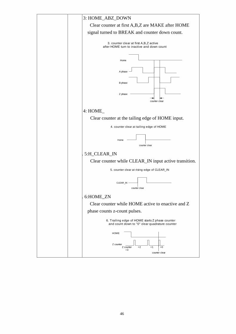
3: HOME_ABZ_DOWN
Clear counter at first A,B,Z are MAKE after HOME
signal turned to BREAK and counter down count.
A phase
B phase
Z phase
Home
counter clear
3. counter clear at first A,B,Z active after HOME turn to inactive and down count
4: HOME_
Clear counter at the tailing edge of HOME input.
Home
counter clear
4. counter clear at tail ing edge of HOME
5. 5:H_CLEAR_IN
Clear counter while CLEAR_IN input active transition.
CLEAR_IN
counter clear
5. counter clear at rising edge of CLEAR_IN
6. 6:HOME_ZN
Clear counter while HOME active to enactive and Z
phase counts z-count pulses.
HOME
Z counterZ counter
=3=2 =1
counter clear
=0
6. Trail ing edge of HOME starts Z phase counter and count down to "0" clear quadrature counter

47
7. 7:H_ZN
Clear counter while Z phase counts z-count pulses.
7. Z phase counter count down to "0" clear quadrature counter
Z counterZ counter
=3=2 =1
counter clear
=0
z_count u16 Z phase count pulses at HOME_ZN and H_ZN homing
mode.
single_cont u8 0: SINGLE, once counter clears, homing mode reset to
NORMAL.
1: CONT, continuous mode, always doing homing function.
LSI3101_HOMING_mode_read
Format : u32 status = LSI3101_HOMING_mode_read (u8 CardID, u8 *homing_mode, u16
*z_count,u8 *single_cont)
Purpose: To read back the LSI3101 card’s high speed counter homing mode.
Parameters:
Input:
Name Type Description
CardID u8 assigned by DIP/ROTARY SW
Output:
Name Type Description
homing_mode u8 Refer explanation of LSI3101_HOMING_mode_set
z_count u16
single_cont u8

48
Compare function
LSI3101_compare_mode_set
Format : u32 status = LSI3101_compare_mode_set (u8 CardID, u8 compare_mode)
Purpose: To set LSI3101 card’s compare mode of high speed counter.
Parameters:
Input:
Name Type Description
CardID u8 assigned by DIP/ROTARY SW
compare_mode u8 0: C_SINGLE (default)
While the compare condition meet, reset the compare
function to compare stop mode.
1: C_FIFO
While the compare condition meet, load new data from
FIFO until FIFO empty to reset the compare function to
compare stop mode.
2: C_AUTO_INC
While the compare condition meet, the new compare
data is incremented by INCREMENT. (set by
LSI3101_compare_increment_set)

49
LSI3101_compare_mode_read
Format : u32 status = LSI3101_compare_mode_read (u8 CardID, u8 *compare_mode)
Purpose: To read back the LSI3101 card’s compare mode of high speed counter.
Parameters:
Input:
Name Type Description
CardID u8 assigned by DIP/ROTARY SW
Output:
Name Type Description
compare_mode u8 0: C_SINGLE (default)
While the compare condition meet, reset the compare
function to compare stop mode.
1: C_FIFO
While the compare condition meet, load new data from
FIFO until FIFO empty to reset the compare function to
compare stop mode.
2: C_AUTO_INC
While the compare condition meet, the new compare
data is incremented by INCREMENT.
LSI3101_counter_set
Format : u32 status = LSI3101_counter_set (u8 CardID, i32 counter_value)
Purpose: To set LSI3101 card’s of speed counter.
Parameters:
Input:
Name Type Description
CardID u8 assigned by DIP/ROTARY SW
counter_value i32 +2147483647 ~ -2147483648

50
LSI3101_counter_read
Format : u32 status = LSI3101_counter_read (u8 CardID, i32 *counter_value)
Purpose: To read back the LSI3101 card’s of speed counter.
Parameters:
Input:
Name Type Description
CardID u8 assigned by DIP/ROTARY SW
Output:
Name Type Description
counter_value i32 +2147483647 ~ -2147483648, counter value on the fly
LSI3101_compare_value_set
Format : u32 status = LSI3101_compare_value_set (u8 CardID, i32 compare_value)
Purpose: To set LSI3101 card’s compare value of high speed counter. One time (Single)
compare mode or auto increment mode or FIFO mode, all need the first comparison
value to start.
Parameters:
Input:
Name Type Description
CardID u8 assigned by DIP/ROTARY SW
compare_value i32 +2147483647 ~ -2147483648
LSI3101_compare_value_read
Format : u32 status = LSI3101_compare_value_read (u8 CardID, i32 *compare_value)
Purpose: To read back the LSI3101 card’s compare value of high speed counter. This command
Can use to read the comparison value for both auto increment or FIFO comparison.
Parameters:
Input:
Name Type Description
CardID u8 assigned by DIP/ROTARY SW
Output:
Name Type Description
compare_value i32 Refer explanation of
LSI3101_compare_value_set

51
LSI3101_compare_increment_set
Format : u32 status = LSI3101_compare_increment_set (u8 CardID, i32 increment_value)
Purpose: To set LSI3101 card’s compare incremental value of high speed counter.
Parameters:
Input:
Name Type Description
CardID u8 assigned by DIP/ROTARY SW
increment_value i32 + 2147483647~ - 2147483648
Note:
New compare value = current compare value + increment_value,
New compare value will be loaded while current compare condition meet.
LSI3101_compare_increment_read
Format : u32 status = LSI3101_compare_increment_read (u8 CardID,
i32 * increment_value)
Purpose: To read back the LSI3101 card’s compare incremental value of high speed counter.
Parameters:
Input:
Name Type Description
CardID u8 assigned by DIP/ROTARY SW
Output:
Name Type Description
increment_value i32 + 2147483647~ - 2147483648
LSI3101_compare_FIFO_clear
Format : u32 status = LSI3101_compare_FIFO_clear (u8 CardID)
Purpose: To discard all the data in compare FIFO of high speed counter.
Parameters:
Input:
Name Type Description
CardID u8 assigned by DIP/ROTARY SW

52
LSI3101_compare_FIFO_threshold_set
Format : u32 status = LSI3101_compare_FIFO_threshold_set (u8 CardID, u16
threshold_value)
Purpose: To set LSI3101 card’s compare FIFO threshold value of high speed counter.
While FIFO remain count reach the threshold, it will generate a almost empty event.
Parameters:
Input:
Name Type Description
CardID u8 assigned by DIP/ROTARY SW
threshold_value u16 1 ~ 1023
Note: The remained FIFO data number equals the threshold value will generate the
FIFO_AL_EMPTY status.
LSI3101_compare_FIFO_threshold_read
Format : u32 status = LSI3101_compare_FIFO_threshold_read (u8 CardID, u16
*threshold_value)
Purpose: To set LSI3101 card’s compare FIFO threshold value of high speed counter.
While FIFO remain count reach the threshold, it will generate a almost empty event.
Parameters:
Input:
Name Type Description
CardID u8 assigned by DIP/ROTARY SW
Output:
Name Type Description
threshold_value u16 1 ~ 1023
LSI3101_compare_FIFO_unused_read
Format : u32 status = LSI3101_compare_FIFO_unused_read (u8 CardID,
u16 *unused_count)
Purpose: To read back LSI3101 card’s compare FIFO un-used count of high speed counter.
Parameters:
Input:
Name Type Description
CardID u8 assigned by DIP/ROTARY SW
Output:
Name Type Description
unused_count u16 1 ~ 1024

53
LSI3101_compare_FIFO_set
Format : u32 status = LSI3101_compare_FIFO_set (u8 CardID, i32 FIFO_data[1024],
u8 rel_abs, u16 size)
Purpose: To fill LSI3101 card’s compare FIFO of high speed counter.
Parameters:
Input:
Name Type Description
CardID u8 assigned by DIP/ROTARY SW
FIFO_data i32 Pointer of FIFO_data, each data is 32bit integer type
rel_abs u8 0: RELATIVE, relative coordinate data
1: ABSOLUTE, absolute coordinate data
size u16 The input FIFO_data size (1~1024)
Note:
1. FIFO_data is a pointer of FIFO_data array with the “size” length.
2. FIFO_data will save to on board hardware FIFO, in spite of the input data type is relative or
absolute, the dll will fill the FIFO at relative data.
3. The relative data must between the range + 2147483647~ - 2147483648.
4. For the absolute coordinate type, the difference of adjacent data must fall in the range +
2147483647~ - 2147483648 to avoid error since the FIFO hardware only accept relative data and
the data size is 32 bit.
4. Before using LSI3101_compare_FIFO_set to fill FIFO, you must already set the first compare
value by LSI3101_compare_value_set as the compare starting point.
LSI3101_counter_start
Format : u32 status = LSI3101_counter_start (u8 CardID, u8 mode)
Purpose: To start counter operation mode
Parameters:
Input:
Name Type Description
CardID u8 assigned by DIP/ROTARY switch
mode u8 0: COUNTER_STOP
counter stops operation.
1: COUNTER_RUN
start operation of counter (including
HOMING).
2: COUNTER_CMP
start operation of counter with compare
and compare output function.

54
LSI3101_counter_mode_read
Format : u32 status = LSI3101_counter_mode_read (u8 CardID, u8 *mode)
Purpose: To read back counter LSI3101 card’s counter start of counter operation mode.
Parameters:
Input:
Name Type Description
CardID u8 assigned by DIP/ROTARY switch
Output:
Name Type Description
mode u8 b3=1, ,COMPARE_OUT FUNCTION
always run else stop
b2=1, ,FIFO COMPARE FUNCTION
always run else stop
b1=1, ,SINGLE/INCREMENT COMPARE
FUNCTION always run else stop
b0=1,COUNTER FUNCTION always run
else stop
LSI3101_counter_stop
Format : u32 status = LSI3101_counter_stop (u8 CardID)
Purpose: To stop counter operation mode
Parameters:
Input:
Name Type Description
CardID u8 assigned by DIP/ROTARY switch

55
Compare segment configuration and compare out mask off
LSI3101_cmp_segment_write
Format : u32 status = LSI3101_cmp_segment_write (u8 CardID,u8 index,i32 start,i32 stop)
Purpose: To write the segment coordinate.
Parameters:
Input:
Name Type Description
CardID u8 assigned by DIP/ROTARY SW
index u8 0: Segment 0
1: Segment 1
2: Segment 2
start i32 Start of mask off segment
stop i32 Stop of mask off segment
LSI3101_cmp_segment_read
Format : u32 status = LSI3101_cmp_segment_read (u8 CardID,u8 index,i32 *start,i32
*stop)
Purpose: To read the segment coordinate.
Parameters:
Input:
Name Type Description
CardID u8 assigned by DIP/ROTARY SW
index u8 0: Segment 0
1: Segment 1
2: Segment 2
Output:
Name Type Description
start i32 Start of mask off segment
stop i32 Stop of mask off segment
LSI3101_mask_off_write
Format : u32 status = LSI3101_mask_off_write (u8 CardID, u8 attribute)
Purpose: To write the mask off attribute.
Parameters:
Input:
Name Type Description
CardID u8 assigned by DIP/ROTARY SW
attribute u8 0: mask off interior
1: mask off exterior

56
LSI3101_mask_off_read
Format : u32 status = LSI3101_mask_off_read (u8 CardID,u8 *attribute)
Purpose: To read back the segment interior or exterior attribute.
Parameters:
Input:
Name Type Description
CardID u8 assigned by DIP/ROTARY SW
Output:
Name Type Description
attribute u8 0: mask off interior
1: mask off exterior
LSI3101_segment_control_write
Format : u32 status = LSI3101_segment_control_write (u8 CardID,u8 index, u8 control)
Purpose: To write the segment control.
Parameters:
Input:
Name Type Description
CardID u8 assigned by DIP/ROTARY SW
index u8 0: Segment 0
1: Segment 1
2: Segment 2
control u8 0:disable
1:enable
LSI3101_segment_control_read
Format : u32 status = LSI3101_segment_control_read (u8 CardID,u8 index,u8 *control)
Purpose: To read the segment control.
Parameters:
Input:
Name Type Description
CardID u8 assigned by DIP/ROTARY SW
index u8 0: Segment 0
1: Segment 1
2: Segment 2
Output:
Name Type Description
control u8 0:disable
1:enable

57
Interrupt function
LSI3101_IRQ_mask_set
Format : u32 status = LSI3101_IRQ_mask_set (u8 CardID,u8 source, u8 mask)
Purpose: Mask off interrupt source of port0 IN07~IN00 or timer,counter
Parameters:
Input:
Name Type Description
CardID u8 assigned by Rotary SW
source u8 0: digital io block
1: timer /counter block
mask u8 Digital block:
Any bit set to 1 of b7~b0 means IN07~IN00 can
generate interrupt
Timer /Counter block:
b4=1, enable timer cross zero to generate interrupt,
else disable.
b3=1, enable counter compare condition meet to
generate interrupt else disable.
b2=1, enable compare FIFO empty to generate
interrupt else disable.
b1=1, enable compare FIFO full to generate
interrupt else disable.
b0=1, enable compare FIFO threshold condition
meet (FIFO_AL_EMPTY) to generate interrupt
else disable.

58
LSI3101_IRQ_mask_read
Format : u32 status = LSI3101_IRQ_mask_read (u8 CardID,u8 source,u8 *mask)
Purpose: read back interrupt mask of port0 b7~b0 or timer/counter
Parameters:
Input:
Name Type Description
CardID u8 assigned by Rotary SW
source u8 0: digital io block
1: timer/counter block
Output:
Name Type Description
mask u8 Digital block:
Any bit set to 1 of b7~b0 means IN07~IN00
can generate interrupt
Timer /Counter block:
b4=1, enable timer cross zero to generate
interrupt, else disable.
b3=1, enable counter compare condition
meet to generate interrupt else disable.
b2=1, enable compare FIFO empty to
generate interrupt else disable.
b1=1, enable compare FIFO full to generate
interrupt else disable.
b0=1, enable compare FIFO threshold
condition meet to generate interrupt else
disable.
LSI3101_IRQ_process_link
Format : u32 status = LSI3101_IRQ_process_link (u8 CardID,
void ( __stdcall *callbackAddr)(u8 CardID))
Purpose: Link irq service routine to driver
Parameters:
Input:
Name Type Description
CardID u8 assigned by Rotary SW
callbackAddr void callback address of service
routine

59
LSI3101_IRQ_enable
Format : u32 status = LSI3101_IRQ_enable (u8 CardID, HANDLE *phEvent)
Purpose: Enable interrupt from selected source
Parameters:
Input:
Name Type Description
CardID u8 assigned by Rotary SW
Output:
Name Type Description
phEvent HANDLE event handle
LSI3101_IRQ_disable
Format : u32 status = LSI3101_IRQ_disable (u8 CardID)
Purpose: Disable interrupt from selected source
Parameters:
Input:
Name Type Description
CardID u8 assigned by Rotary SW
60
LSI3101_IRQ_status_read
Format : u32 status = LSI3101_IRQ_status_read (u8 CardID,u8 source, u8 *Event_Status)
Purpose: To read back the interrupt status to identify the source
Parameters:
Input:
Name Type Description
CardID u8 assigned by Rotary SW
source u8 0: digital io block
1: timer block
Output:
Name Type Description
Event_Statu
s
u8 Digital block:
Any bit set to 1 of b7~b0 means port0 IN07~IN00
generate interrupt
Timer /counter block:
b4:S_TIMER
Timer cross 0 will set S_TIMER flag
b3:S_COMPARE
Compare condition meet will set S_COMPARE flag
b2:S_FIFO_EMPTY
FIFO unused count=0 will set S_FIFO_EMPTY flag
b1:S_FIFO_FULL
FIFO count = 1023 will set S_FIFO_FULL flag
b0:S_FIFO_AL_EMPTY
FIFO unused count = FIFO_THRESHOLD will set
S_FIFO_AL_EMPTY flag
Note:
1. Status read back will also clear the on board status register.
2. The status will reflect the on board digital input or timer count up status are irrelevant to the
IRQ_MASK

61
Security function
LSI3101_password_set
Format : u32 status = LSI3101_password_set (u8 CardID,u16 password[5])
Purpose: To set password and if the password is not all “0”, security function will be enabled.
Parameters:
Input:
Name Type Description
CardID u8 assigned by DIP/ROTARY SW
password[5] u16 Password, 5 words
Note: If the password is all “0”, the security function is disabled.
LSI3101_password_change
Format : u32 status = LSI3101_password_change (u8 CardID,u16 Oldpassword[5],
u16 password[5])
Purpose: To replace old password with new password.
Parameters:
Input:
Name Type Description
CardID u8 assigned by DIP/ROTARY SW
Oldpassword [5] u16 The previous password
password[5] u16 The new password to be set
LSI3101_password_clear
Format : u32 status = LSI3101_password_clear (u8 CardID,u16 password[5])
Purpose: To clear password, to set password to all “0”, i.e. disable security function.
Parameters:
Input:
Name Type Description
CardID u8 assigned by DIP/ROTARY SW
password[5] u16 The password previous set
62
LSI3101_security_unlock
Format : u32 status = LSI3101_security_unlock (u8 CardID,u16 password[5])
Purpose: To unlock security function and enable the further operation of this card
Parameters:
Input:
Name Type Description
CardID u8 assigned by DIP/ROTARY SW
password[5] u16 The password previous set
LSI3101_security_status_read
Format : u32 status = LSI3101_security_status_read (u8 CardID,u8 *lock_status,
u8 *security_enable )
Purpose: To read security status for checking if the card security function is unlocked.
Parameters:
Input:
Name Type Description
CardID u8 assigned by DIP/ROTARY SW
Output:
Name Type Description
lock_status u8 0: UNLOCKED
security unlocked
1: LOCKED
security locked
2: DEAD LOCK
dead lock (must return to original
maker to unlock)
security_
enable
u8 0: security function disabled
1: security function enabled
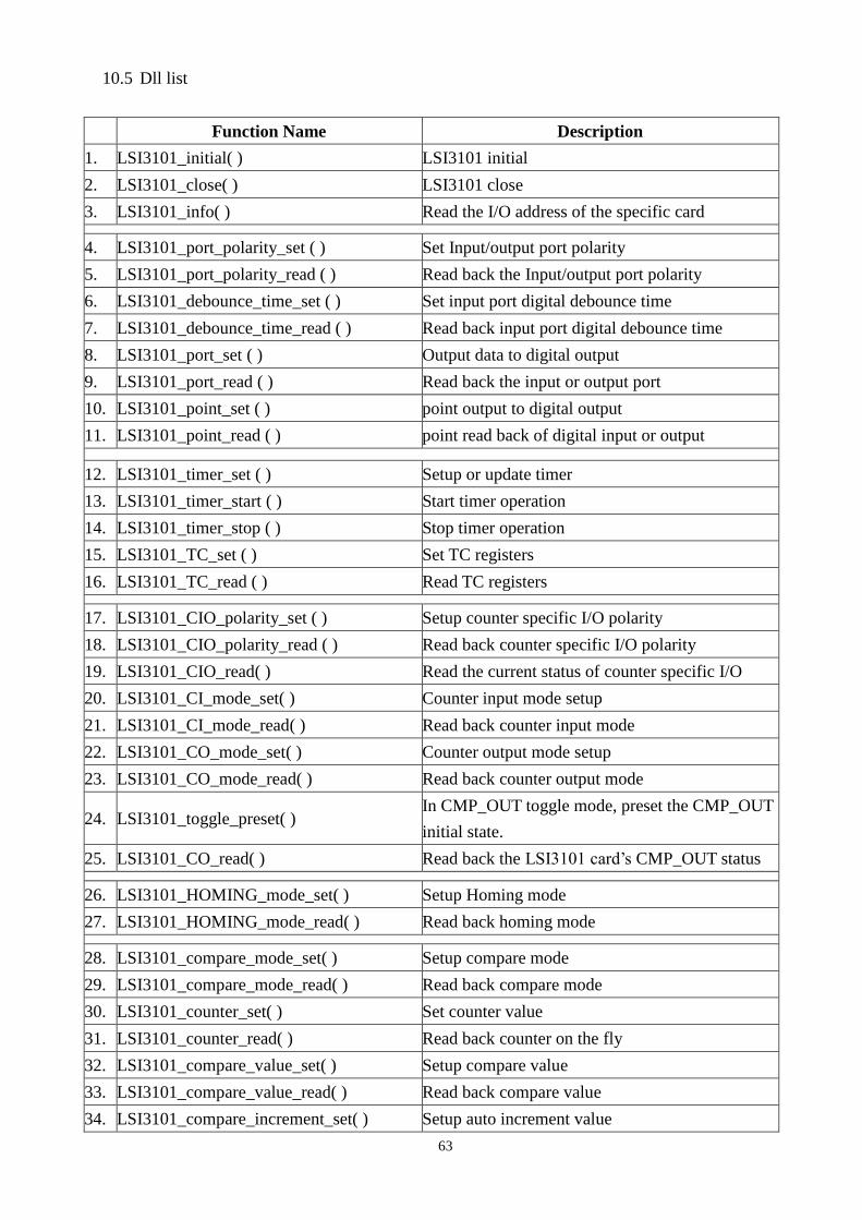
63
10.5 Dll list
Function Name Description
1. LSI3101_initial( ) LSI3101 initial
2. LSI3101_close( ) LSI3101 close
3. LSI3101_info( ) Read the I/O address of the specific card
4. LSI3101_port_polarity_set ( ) Set Input/output port polarity
5. LSI3101_port_polarity_read ( ) Read back the Input/output port polarity
6. LSI3101_debounce_time_set ( ) Set input port digital debounce time
7. LSI3101_debounce_time_read ( ) Read back input port digital debounce time
8. LSI3101_port_set ( ) Output data to digital output
9. LSI3101_port_read ( ) Read back the input or output port
10. LSI3101_point_set ( ) point output to digital output
11. LSI3101_point_read ( ) point read back of digital input or output
12. LSI3101_timer_set ( ) Setup or update timer
13. LSI3101_timer_start ( ) Start timer operation
14. LSI3101_timer_stop ( ) Stop timer operation
15. LSI3101_TC_set ( ) Set TC registers
16. LSI3101_TC_read ( ) Read TC registers
17. LSI3101_CIO_polarity_set ( ) Setup counter specific I/O polarity
18. LSI3101_CIO_polarity_read ( ) Read back counter specific I/O polarity
19. LSI3101_CIO_read( ) Read the current status of counter specific I/O
20. LSI3101_CI_mode_set( ) Counter input mode setup
21. LSI3101_CI_mode_read( ) Read back counter input mode
22. LSI3101_CO_mode_set( ) Counter output mode setup
23. LSI3101_CO_mode_read( ) Read back counter output mode
24. LSI3101_toggle_preset( ) In CMP_OUT toggle mode, preset the CMP_OUT
initial state.
25. LSI3101_CO_read( ) Read back the LSI3101 card’s CMP_OUT status
26. LSI3101_HOMING_mode_set( ) Setup Homing mode
27. LSI3101_HOMING_mode_read( ) Read back homing mode
28. LSI3101_compare_mode_set( ) Setup compare mode
29. LSI3101_compare_mode_read( ) Read back compare mode
30. LSI3101_counter_set( ) Set counter value
31. LSI3101_counter_read( ) Read back counter on the fly
32. LSI3101_compare_value_set( ) Setup compare value
33. LSI3101_compare_value_read( ) Read back compare value
34. LSI3101_compare_increment_set( ) Setup auto increment value

64
35. LSI3101_compare_increment_read( ) Read back auto increment value
36. LSI3101_compare_FIFO_clear( ) Clear FIFO
37. LSI3101_compare_FIFO_threshold_set( ) Setup FIFO near empty threshold
38. LSI3101_compare_FIFO_threshold_read( ) Read back FIFO near empty threshold
39. LSI3101_compare_FIFO_unused_read( ) Read back the remained FIFO size
40. LSI3101_compare_FIFO_set( ) Setup FIFO data
41. LSI3101_counter_start( ) Start counter function
42. LSI3101_counter_mode_read( ) Read back counter working mode
43. LSI3101_counter_stop( ) Stop counter function
44. LSI3101_cmp_segment_write ( ) Write the segment coordinate
45. LSI3101_cmp_segment_read ( ) Read the segment coordinate
46. LSI3101_mask_off_write ( ) Write the mask off attribute
47. LSI3101_mask_off_read ( ) Read the mask off attribute
48. LSI3101_segment_control_write( ) Write the segment control
49. LSI3101_segment_control_read( ) Read the segment control
50. LSI3101_IRQ_mask_set ( ) Setup interrupt source mask
51. LSI3101_IRQ_mask_read ( ) Read back interrupt source mask
52. LSI3101_IRQ_process_link ( ) Link interrupt service routine to driver
53. LSI3101_IRQ_enable ( ) Enable interrupt function
54. LSI3101_IRQ_disable ( ) Disable interrupt function
55. LSI3101_IRQ_status_read( ) Read back irq status
56. LSI3101_password_set ( ) Set software key
57. LSI3101_password_change ( ) Change software key
58. LSI3101_password_clear ( ) Clear software key
59. LSI3101_security_unlock ( ) Unlock software key
60. LSI3101_security_status_read ( ) Read software key status

65
11. LSI3101 Error codes summary
11.1 LSI3101 Error codes table
Error
Code Symbolic Name Description
0 DRV_NO_ERROR No error.
2 DRV_INIT_ERROR Initial error
3 DRV_UNLOCK_ERROR Security unclock failure
4 DRV_LOCK_COUNTER_ERROR Dead lock, unclock failure more than 10 times
5 DRV_SET_SECURITY_ERROR Password overwrite error
100 DEVICE_IO_ERROR Device drive error
101 DRV_NO_CARD No card find error
102 DRV_DUPLICATE_ID Card duplicate error
300 LSI_ID_ERROR CardID setting error, CardID doesn’t match the
DIP SW setting
301 LSI_COUNTER_MODE_ERROR LSI3101_set_counter_mode(),"mode" parameter
out of range.
302 LSI_TIMER_CONSTANT_ERROR LSI3101_timer_set(),"time" parameter out of
range.
303 LSI_CI_MODE_ERROR LSI3101_CI_mode_set(),"control" parameter out
of range.
304 LSI_MULTIPLE_RATE_ERROR LSI3101_CI_mode_set (),"mode" parameter out
of range.
305 LSI_POINT_ERROR "point" parameter out of range.
306 LSI_CO_ERROR LSI3101_CO_mode_set (),"mode" parameter out
of range.
307 LSI_HOME_MODE_ERROR LSI3101_HOMING_mode_set(),"mode"
parameter out of range.
308 LSI_COMPARE_MODE_ERROR LSI3101_compare_mode_set(),"mode" parameter
out of range.
309 LSI_POLARITY_ERROR "polarity" parameter out of range.
310 LSI_INCREMENT_ERROR LSI3101_compare_increment_set (),"control"
parameter out of range.
311 LSI_COMPARE_OUT_MODE_ERROR LSI3101_CO_mode_set (),"control" parameter
out of range.
312 LSI_FIFO_FULL_ERROR push into new data while FIFO full
313 LSI_FIFO_EMPTY_ERROR pop out data while FIFO empty
314 LSI_FIFO_ERROR LSI3101_compare_FIFO_set (),"control"
parameter out of range.

66
315 LSI_THRESHOLD_ERROR LSI3101_compare_FIFO_threshold_set
(),"control" parameter out of range.
316 LSI_COUNTER_ERROR LSI3101_counter_start (),"control" parameter out
of range.
317 LSI_IRQ_MASK_ERROR LSI3101_IRQ_mask_set (),"control" parameter
out of range.
400 LSI_DRIVER_NOT_SUPPORT driver not support interrupt function
500 PORT_ERROR Function input parameter error.
Parameter out of range.
501 DEBOUNCE_MODE_ERROR LSI3101_debounce (),"control" parameter out of
range.
502 INDEX_ERROR TC register index error
503 SOURCE_ERROR IRQ source parameter out of range.