Embed Size (px)
Citation preview

LSTC Barriers and Dummies
Dilip Bhalsod
16th Oasys LS-DYNA Users’
Meeting March 12th 2019

4
LSTC Family of Barriers
ECER95 shell
IIHS shell/solid
ODB shell/hybrid
214 - 301 shell/solid
AE-MDB shell
RCAR Barrier OMDB MPDB MCB

FMVSS 214 Barrier
5

6
FMVSS 214 Barrier
• Pure solid element version - 145,000 elements
• Shell element main block and bumper - 550,000 shells.
7
FMVSS 214 Barrier - Updates
• The stiffness of the barrier honeycomb parts has been improved, based upon feedback from
clients, for better correlation of force and deflection response in full vehicle crash tests.
• Soft Constraint Formulation (SOFT) on optional card A of
*CONTACT_AUTOMATIC_SINGLE_SURFACE (CID: 3) definition corresponding to the self-
contact of the barrier parts has been set to 1.
• This serves to decrease the computational expense associated with this contact.
• The width of the honeycomb impact face in the 214 barrier and 301 barrier models has been
adjusted to 1676 mm, to meet the width specified in NHTSA guidelines

301 Barrier Construction
• 'FMVSS 301 Barrier' model has been developed based upon the 'FMVSS 214 Barrier'
and calibrated to a series of customer proprietary tests.
• The 301 barrier model has been updated to represent the accurate ground clearance
of 229 mm between the bottom of the honeycomb block and ground.
9

10
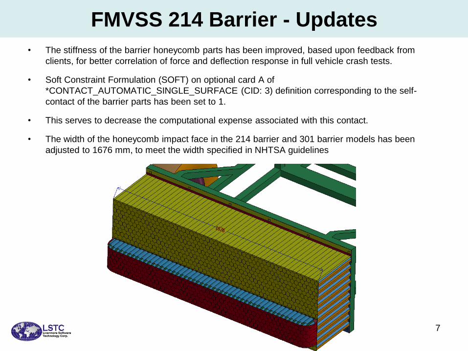
301barrier for 70% Rear offset tests
– This barrier was originally developed for side
impact tests
– Energy levels are much higher and
deformations are very high for these tests
– Recently modified to meet 6 customer tests
– Bumper now meshed using shells
– Model released in 2016
11
6 customer tests for 70% rear offset

27 deg. Angled 214 Barrier
12
• 'FMVSS 214 Barrier' model with the four wheels inclined at 27 deg. to the longitudinal axis has
been recently developed.
• *INITIAL_VELOCITY_GENERATION card has been added to spin the wheels of the cart.
• Spinning wheels enables accurate calculation of Kinetic Energy of the barrier in full vehicle impact
simulation.
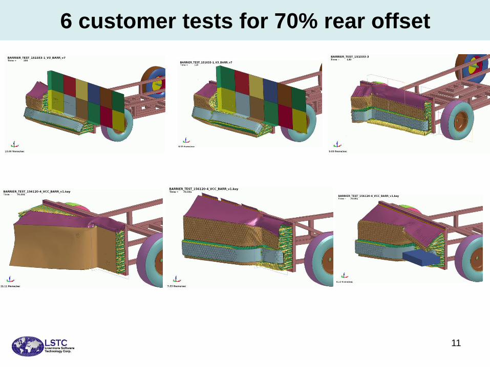
Moving Contoured Barrier - Overview
• Moving Contoured Barrier Model has been built for Fuel System Integrity testing of
School Bus, based on the specifications given in the FMVSS Standard No. 301
13

Moving Contoured Barrier - Overview
14

15
IIHS Barrier - Updates
• Shell thickness update parameter (ISTUPD) has been activated in the
*CONTROL_SHELL card, with a part set of parts for thickness update assigned to the
parameter PSSTUPD.
• A shell element bumper was constructed and added to the IIHS barrier model to replace
the solid element bumper.
Solid bumper
replaced with
Shell honeycomb lattice

16
IIHS Pole
Solid element version – 120,000 elements
Shell element version – 570,000 elements
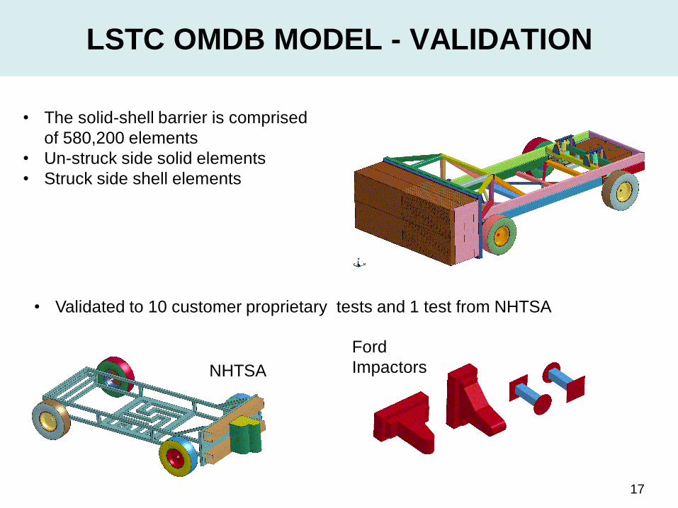
LSTC OMDB MODEL - VALIDATION
17
• The solid-shell barrier is comprised
of 580,200 elements
• Un-struck side solid elements
• Struck side shell elements
• Validated to 10 customer proprietary tests and 1 test from NHTSA
NHTSA
Ford
Impactors
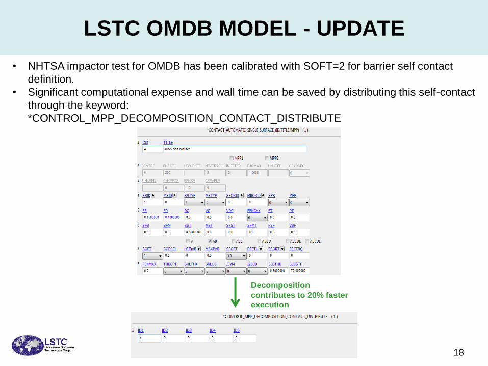
LSTC OMDB MODEL - UPDATE
18
• NHTSA impactor test for OMDB has been calibrated with SOFT=2 for barrier self contact
definition.
• Significant computational expense and wall time can be saved by distributing this self-contact
through the keyword:
*CONTROL_MPP_DECOMPOSITION_CONTACT_DISTRIBUTE
Decomposition
contributes to 20% faster
execution
Mobile Progressive Deformable Barrier
19

Mobile Progressive Deformable Barrier - Background
• This is the initial release of Mobile Progressive Deformable Barrier.
• This model is based on revised specifications for the offset frontal impact procedure
released by European NCAP Programme in October 2017.
• This model is expected to be used for 2020 European NCAP Programme.
• The deformable honeycomb face of the barrier is mounted on its cart.
20
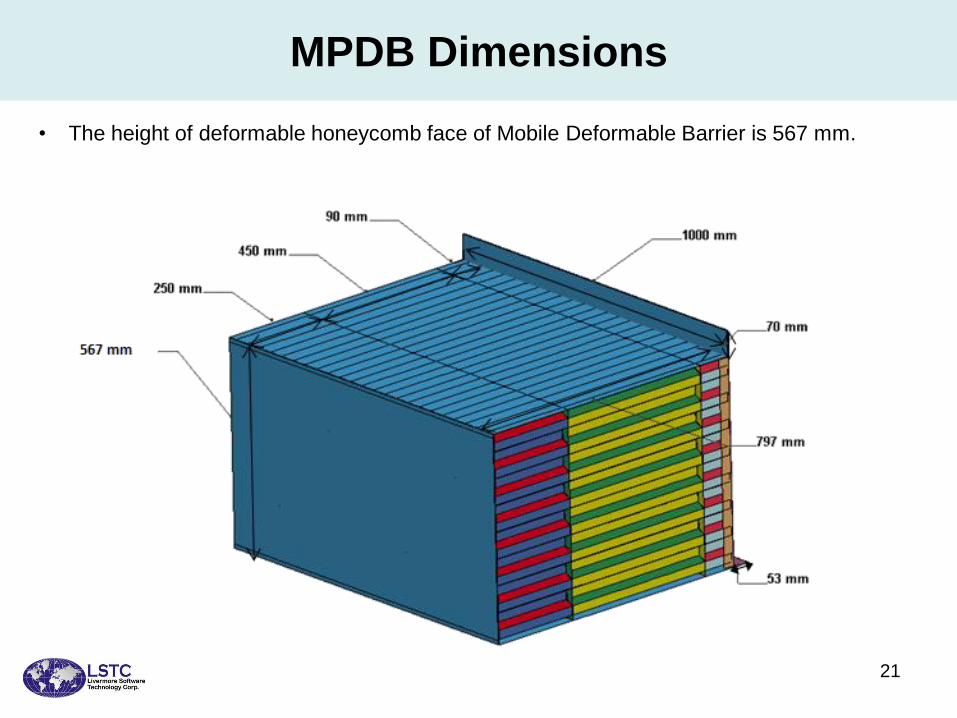
MPDB Dimensions
21
• The height of deformable honeycomb face of Mobile Deformable Barrier is 567 mm.

Validation Tests – Force vs Deflection Behavior
22
LSTC Dummy Models Update February 2019
Current Improvements and Developments
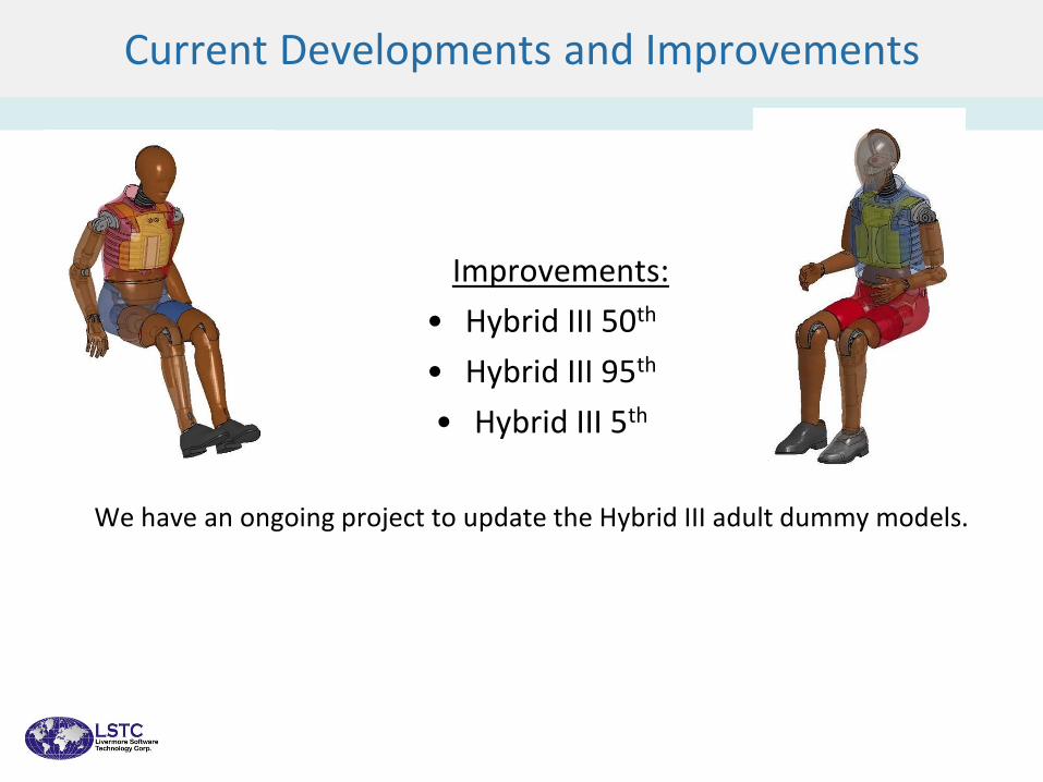
Improvements:
• Hybrid III 50th
• Hybrid III 95th
• Hybrid III 5th
We have an ongoing project to update the Hybrid III adult dummy models.
Current Developments and Improvements

Current Improvements and Developments
New Developments:
• WorldSID 50th
• Hybrid III 3-year old
• Hybrid II
Current Developments and Improvements
First version of WorldSID 50th detailed model was released in June 2018

Number of
nodes
~450K
Number of
elements
~430K
Number of
parts
268
Constrained
joints
14
WorldSID 50th
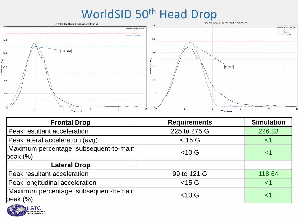
WorldSID 50th Head Drop
Frontal Drop Requirements Simulation
Peak resultant acceleration 225 to 275 G 226.23
Peak lateral acceleration (avg) < 15 G <1
Maximum percentage, subsequent-to-main
peak (%) <10 G <1
Lateral Drop
Peak resultant acceleration 99 to 121 G 118.64
Peak longitudinal acceleration <15 G <1
Maximum percentage, subsequent-to-main
peak (%) <10 G <1
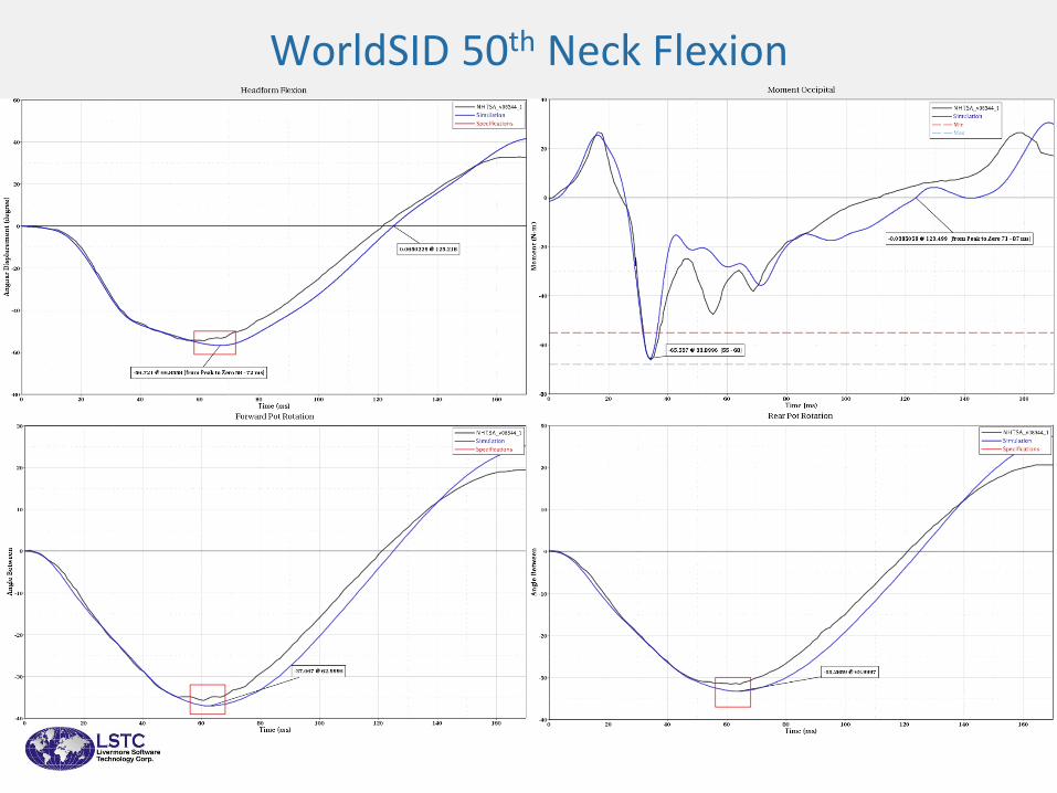
WorldSID 50th Neck Flexion

WorldSID 50th Neck Flexion
Variables Requirements Simulation
Pendulum Velocity change at 4 ms 0.77 to 1.04 0.870
Pendulum Velocity change at 8 ms 1.6 to 2.16 2.087
Pendulum Velocity change at 12 ms 2.43 to 3.29 3.130
Variables Requirements Simulation
Max headform flexion angle, beta (degree) 50 to 61 56.721
Decay time of peak headform flexion to 0 degrees (ms) 58 to 72 58.362
Peak occipital condyles moment (Nm) 55 to 68 65.537
Peak occipital condyles moment decay to zero (ms) 71 to 87 89.599
Peak forward potentiometer ang. disp. (degree) 32 to 39 37.067
Time for peak forward potentiometer angular disp. (ms) 56 to 68 63.000
Peak rearward potentiometer ang. disp. (degree) 30 to 37 33.286
Time for peak rearward potentiometer angular disp. (ms) 56 to 68 64.000

WorldSID 50th Shoulder Certification
Variables Requirements Simulation
Peak pendulum
force
2.6 to 3.3 kN 3.27107
Shoulder rib
deflection
35 to 44 mm 41.0205
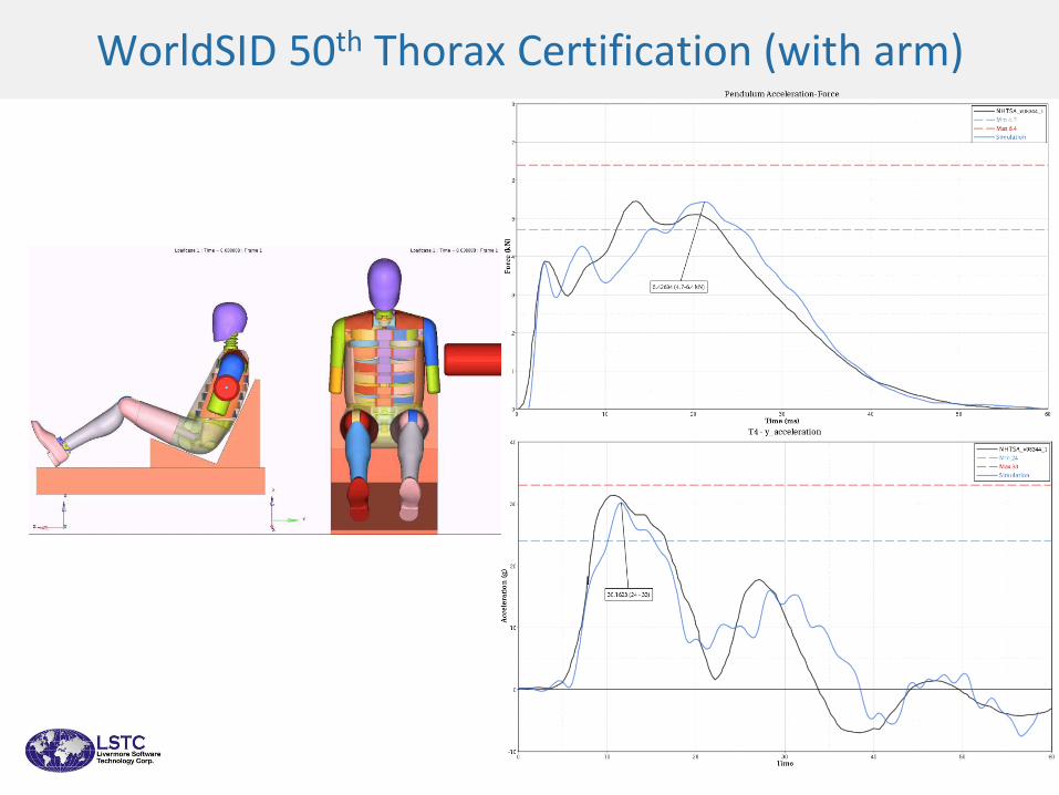
WorldSID 50th Thorax Certification (with arm)
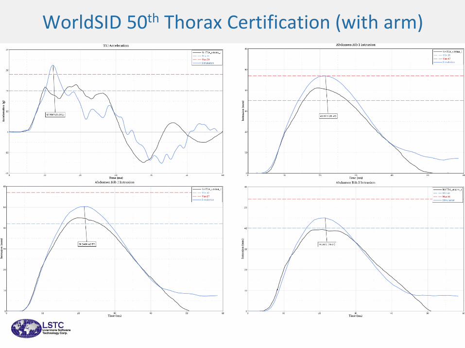
WorldSID 50th Thorax Certification (with arm)
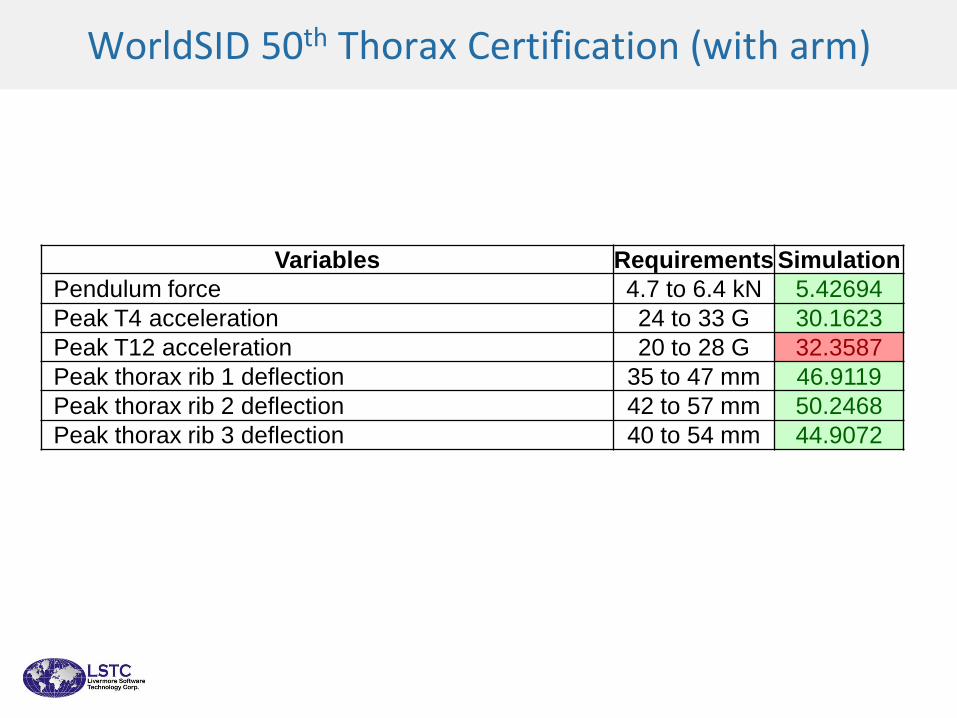
WorldSID 50th Thorax Certification (with arm)
Variables Requirements Simulation
Pendulum force 4.7 to 6.4 kN 5.42694
Peak T4 acceleration 24 to 33 G 30.1623
Peak T12 acceleration 20 to 28 G 32.3587
Peak thorax rib 1 deflection 35 to 47 mm 46.9119
Peak thorax rib 2 deflection 42 to 57 mm 50.2468
Peak thorax rib 3 deflection 40 to 54 mm 44.9072
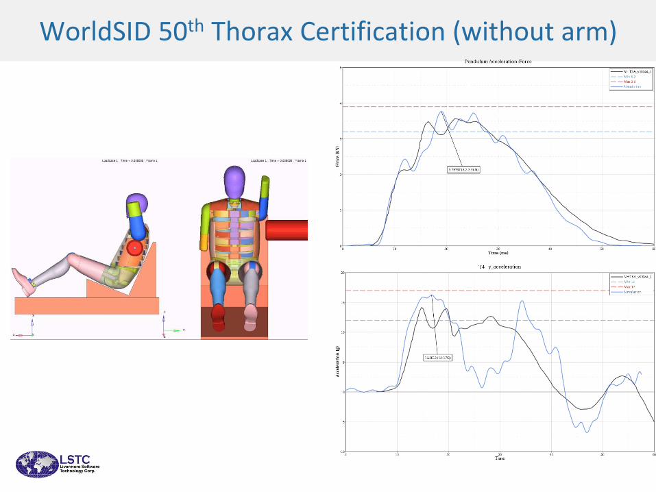
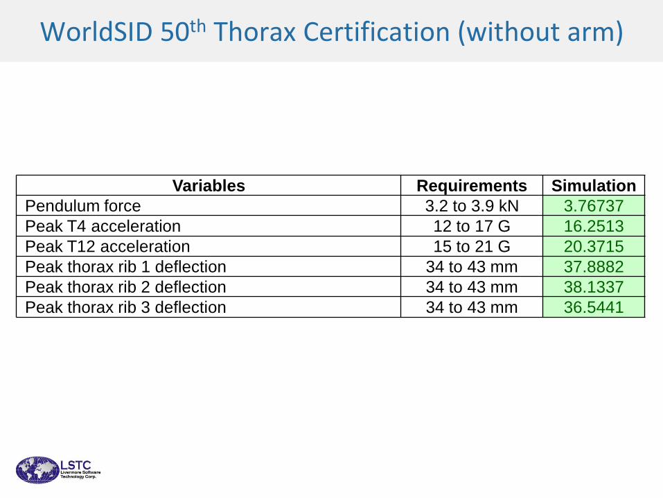
WorldSID 50th Thorax Certification (without arm)

WorldSID 50th Thorax Certification (without arm)
WorldSID 50th Thorax Certification (without arm)
Variables Requirements Simulation
Pendulum force 3.2 to 3.9 kN 3.76737
Peak T4 acceleration 12 to 17 G 16.2513
Peak T12 acceleration 15 to 21 G 20.3715
Peak thorax rib 1 deflection 34 to 43 mm 37.8882
Peak thorax rib 2 deflection 34 to 43 mm 38.1337
Peak thorax rib 3 deflection 34 to 43 mm 36.5441
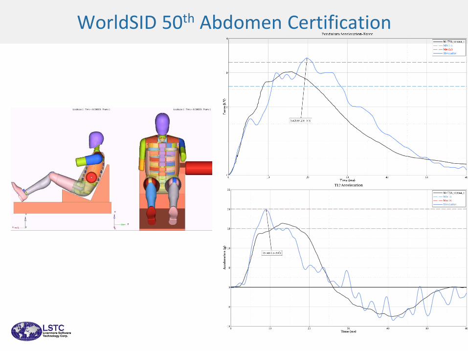
WorldSID 50th Abdomen Certification
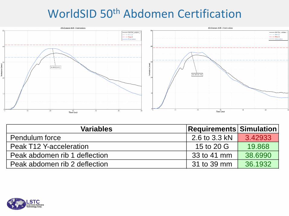
WorldSID 50th Abdomen Certification
Variables Requirements Simulation
Pendulum force 2.6 to 3.3 kN 3.42933
Peak T12 Y-acceleration 15 to 20 G 19.868
Peak abdomen rib 1 deflection 33 to 41 mm 38.6990
Peak abdomen rib 2 deflection 31 to 39 mm 36.1932

WorldSID 50th Pelvis Certification

WorldSID 50th Pelvis Certification
Variables Requirements Simulation
Pendulum force 6.3 to 7.8 kN 7.31721
Peak acceleration along y axis 41 to 51 G 44.7952
Peak T12 Y-acceleration 10 to 14 G 11.9579
41
THANK YOU
We thank all the OEMs who provided us with the test data for the development of dummies and barrier models.


![Software independence: impact on product development plan in … · 2015. 2. 3. · [6] LS-DYNA Theory Manual, LSTC. [7] LS-DYNA 960 manual k vol. 1, LSTC. [8] LS-DYNA 960 manual](https://img.pdfslide.net/doc/110x75/61027a6a2e7e1578d5597bad/software-independence-impact-on-product-development-plan-in-2015-2-3-6-ls-dyna.jpg)