Embed Size (px)
Citation preview

, (0
N Power Line Aberrations and Their Effects on Health Care Facility
Microprocessor Equipment
Major Thomas N. Romeyn, USAF, MSC, CBET
Department of Biomedical Engineering
Case Western Reserve University
Clinical Engineering Project
6Apr1 1990 D T ICELECTE
AUGO1
*L'~ST~t JT:N ATX
c!ri vt d 90Os :

Form ApprovedREPORT DOCUMENTATION PAGE OMB No. 0704-0188
Public reporting burden for this collection of information is estimated to average I hour per response, including the time for reviewing instructions. searchrng existing data sources.gathering and maintainig the data needed. and completing and reie-ng the collection of informatiOn Send comments regarding this burden estimate or any other aspect of thiscollecion of information, including suggestions for reducing this ouren to Washington Headquarters Services. Directorate Tor information Operations and Reports. 1215 JeffersonDavis HighwaV. Suite 1204, Arlington, VA 222024302. and to the Office of Management and Budget. Paperwork Reduction Project (0704-0188). Washing Z.. 20503.
1. AGENCY USE ONLY (Leave blank) 2. REPORT DATE 3. REPORT TYPE AND DATES COVERED
; 1990 Thesis_/- ____t_____4. TITLE AND SUBTITLE S. FUNDING NUMBERS
POWER LINE ABERRATIONS AND THEIR EFFECTS ON HEALTHCARE FACILITY MICROPROCESSOR EQUIPMENT
6. AUTHOR(S)
THOMAS N. ROMEYN
7. PERFORMING ORGANIZATION NAME(S) AND ADDRESS(ES) 8. PERFORMING ORGANIZATION
AFIT Student at: Case Wester Reserve University REPORT NUMBER
AFIT/CI/CIA -90-057
9. SPONSORING/MONITORING AGENCY NAME(S) AND ADDRESS(ES) 10. SPONSORING/MONITORING
AFIT/CI AGENCY REPORT NUMBER
Wright-Ptatterson AFB OH 45433
11. SUPPLEMEN' NOTES
12a. DISTRIBUTION /AVAILABILITY STATEMENT 12b. DISTRIBUTION CODE
Approved for Public Release lAW AFR 190-1Distribution UnlimitedERNEST A. HAYGOOD, 1st Lt, USAFExecutive Officpr, Civilian Institution Programs
13. ABSTRACT (Maximum 200 words)
14. SUBJECT TERMS 15. NUMBER OF PAGES
8516. PRICE CODE
17. SECURITY CLASSIFICATION 18. SECURITY CLASSIFICATION 19. SECURITY CLASSIFICATION 20. LIMITATION OF ABSTRACTOF REPORT OF THIS PAGE OF ABSTRACT
UNCLASSIFIEDNSN 7540-01-280-5500 Standard Form 298 (Rev 2-89)

Table of Contents
1 Introduction .......................................................... 41.1 Introduction ...................................................... 41.2 Goals of Power Protection/Condition Systems....................................... 61.3 Purpose of Paper ........................................................................ 7
2 Discussion ................................................................................... 82.1 Definition of Power Terms ................... .......... 82.2 Frequent Sources of Power line Aberrations ......................................... 122.3 Definition IEEE Standards for Surge Voltages in Low-Voltage ac powercircuits................................ .... ... **....... 172.4 Power Supply Design ................................................................... 252.5 Filters ................................................................................... 34
3 Methods and Devices..................... ..... 373.1 Power Conditioning..................................................................... 37
3.1.1 Types of Power Conditioning ................................................... 403.1.2 Sequence of Power Conditioning Steps ........................................ 43
3.2 Power Protection........................................................................ 463.3 Electromagnetic Interference (EMI) protection...................................... 513.4 Generator Transfer Switches........................................................... 573.5 Bottom Line ............................................................................. 583.6 Future or Not Too Distant Future...................................................... 66
4 Conclusion .................................................................................... 71
5 Appendix .................................................................................... 745.1 List of Terms............................................................................ 745.2 Points to consider when purchasing an Uninterruptible Power System (U.P.S.)....i i....................................................................................... 785.3 Efcts of 60 Hz Current on Humans ................................................. 82
6 References .................................................................................... 83
Acesnlon For
NTI1S GRA&I
V~lLIC A
ju s t If C 10 f o
AV12~' ~ Codes
uik - 'or __
Dist

Table of Figures
1. Incidence Rate of Harmful Power Line Disturbances ............................................ 52. Categories of Pow er A berrations ............................................................................. 93. Pictures of Various Power D isturbances ..................................................................... 114. Voltage Waveform Sequence During Typical Power Transfer ............................... 185. IEEE Open-Circuit Voltage Test Wave .................................................................... 226. Location Categories from IEEE Std 587-1980 ........................................................ 247. Unidirectional Waveshapes (ANSI/IEEE Std 28-1974) ........................................... 258. IEEE Suggested Test Circuits ....................................... 269. Brute-force Half-wave Power Supply ...................................................................... 2710. Brute-force Full-wave Power Supply ....................................................................... 2811. Brute-force Bridge Power Supply ........................................................................... 2812. Ferroresonant Voltage Regulation System .............................................................. 3013. Linear Power Supply System .................................................................................. 3214. Switching Power Supply (Pulse-width modulation) ............................................... 3315. Switching Power Supply (Phase-control modulation) ....................... 3416. Sim ple Capacitive Filtering System ......................................................................... 3617. Sim ple Inductor Filtering System ........................................................................... 3618. Inductive-Capacitive (LC) Filtering System ........................................................... 3719. Block Diagram of Uninterruptible Power Supply System ..................................... 4820. U. S. and West German Standards for EMI ............................................................. 5421. Recommended Line Impedance Stabilization Network (LISN) ............................. 5522. Sample Filter Systems that meet EMI Standards .................................................... 5623. Block Diagram of the Power Supply IC (HV-1205) .......................... 6724. Diagram of the Power Supply IC (HV-1205) ........................................................ 70
iii

Table of Tables
1. Susceptibility Ranges of Various Semiconductor Devices ....................................... 152. Voltages and Currents for the Indoor Environment .................................................. 233. Advantages/Disadvantages of Dedicated Power Line ............................................. 604. Advantages/Disadvantages of Surge Suppressor .................................................... 615. Advantages/Disadvantages of Isolated Transformer ................................................ 626. Advantages/Disadvantages of Power Distribution System ....................................... 637. Advantages/Disadvantages of Ferroresonant Transformer ....................................... 648. Advantages/Disadvantages of Low-Impedance Technology .................................... 659. Advantages/Disadvantages of UPS ........................................................................... 6610. Effects of 60 Hz Current on Humans ....................................................................... 82
iv

1 Introduction
1.1 Introduction
'You are working on a project and suddenly the lights go out. Just as suddenly, the lights
return and the phone/beeper begins ringing off the hook with reports of equipment that is down.
Another scenario, suddenly the lights dim for an extended period of time. As the lights return to
normal intensity or even before the lights return to normal intensity, the phone/beeper begins
ringing. There are countless scenarios, the causes numerous, and the solutions many and
varying.
Since 1975, technology has led to the invasion of microelectronic and computer- controlled
medical equipment. This invasion comes as a blessing, because better patient care is possible,
and as a curse trying to keep these electrical gadgets operating. The invasion of technologically
advanced equipment has greatly increased capabilities in radiology (examples : Digital
Subtraction, High Frequency Generators, Anatomical Programmed Generators, improved
Cardiovascular image systems), Magnetic Resonance (MR), Computerized tomography (CT)
X-ray, Ultrasound, patient history data base systems, patient diagnostic systems, improved
Clinical laboratory equipment, and lasers to mention only a few areas. [11:2] When the utility
power lines deviate from the norm, (typically values 110, 220, or 277/440 volts line to ground)
the problem(s) begins.
Various individuals and organizations have studied power system aberrations. A two year
study conducted by Bell laboratories in several geographic locations within the United States
demonstrated the average location experiences approximately 25 power line aberrations per year
and of these, 87% were sags below 96 volts. In 1970, Martzloff and Hahn performed a two year
study on power aberrations for The Institute of Electrical and Electronics Engineers (IEEE).
Their study revealed the average residence or light industry experiences two spikes or surges per
4

U
1 hour. The typical values measured were 1500 to 2500 volts (peak values) although 5600 volts
were measured during lightning storms. In 29 different geographic locations within the United
States, International Business Machine (IBM ®) conducted a power aberrations study. Again,
3 spikes were the most common problem occurring with an average of 62.2 spikes per month.
[21:145] Figure 1 displays the results of the 1974 IEEE test. 48.8% of the power aberrations
I were spikes. [11:10] Recently, James D. Vail conducted a study on what happens electrically
Incidence Rate of Harmful Power Line Disturbances
IU
Voltage Surges (39.5%) Voltage Spikes (48.8%)
3Undervoltages (11.2%) Voltage Outages (0.5%)
*Figure I
Reprinted from Howard C. Cooper, "Power Conditioning to protect computers and ElectronicEquipment", American Society for Hospital Engineering of the American Hospital Association,June 1984, p. 10.
5

I
during an emergency-generator test. The test revealed voltage deviations (sags) along with
normal-mode and common-mode spikes or impulses occurred during the transfer to generator or
the transfer back to utility power. The most significant factors affecting voltage deviations were
type of generator, age of facility, and type of transfer switch utilized. [45:22-25] These studies
differ on the quantity and the determination of the most significant problem(s) (spikes, surges, or
sags), but they all conclude power line aberrations are a significant problem particularly for
microprocessors and computer-controlled equipment. [21:145]
3 1.2 Goals of Power Protection/Condition Systems
The ultimate goal of a power protection system is to neutralize undesireable voltages and
3 currents. If the protection system is unable to totally neutralize the power aberrations the
protection system must alter the aberrations to an acceptable level. People, buildings,
I equipment, software and assorted other items are protected by these protection systems.
National Electrical Code (NEC ®), Underwriters Laboratories (UL ®), The Institute of Electrical
and Electronics Engineers (IEEE ®), Joint Commission on Accreditation of Health Care
3Organizations (JCAH ®), National Fire Protection Association (NFPA ®) and various Federal
organizations have developed codes and guidance for the protection system. Table 10 shows the
I human body's response to various sizes of electrical currents. [14:x] This paper is directed to
protection systems for buildings, equipment, software and assorted equipment items.
Norman H. Haskell, Jr. defines power protection as one simple principle "equalization of
3 potential". [14:xii] Power conditioning and power protection are the two principle power
protection systems. The goal of power conditioning is to take cornmercial ac (raw) utility power
3with its power aberrations (transients, surges, sags, noise, spikes, etc.) and smooth or stabilize the
power into "computer" grade ac power. Power conditioning does not deal with blackouts or
I
II

U
I brownouts but with power aberrations by regulation or suppression. [11:2-3]
I The goal of power protection is to take the same commercial ac power, smooth or stabilize
the power into "computer" grade power and at the same time provide coverage for power
3 deficiency conditions such as blackouts and brownouts. Blackouts, even those lasting only a
thousandth of a second, can interrupt the routine of microprocessor controlled equipment. The
I average blackout lasts less than six (6) seconds. Most power companies do not consider a power
outage as a blackout until at least three (3) minutes have passed. At other times, line voltage can
sag (low voltage or brownout) resulting in malfunction of the microprocessor's power supplies
3 and in turn affect the performance of the equipment if the sag lasts long enough or drops low
enough. Regulation procedures cannot deal with these types of power deficiency conditions.
I [5:84] Power conditioning deals with power fluctuations by employing a combination of
regulation and/or suppression and a backup power source to overcome power fluctuations
including blackout or brownout conditions.I1.3 Purpose of Paper
5The purpose of this paper is to provide a practical technical guide to power
conditioning/protection for the health care facility's equipment environment. The following
I main items will be considered:
I a) define the various power aberration problems,
b) cost effective power conditioning/protection systems,
I c) methods to reduce/eliminate equipment malfunction due to power aberrations,
d) reduce maintenance contracts and overhead costs,
I e) reduce/eliminate crisis situations due to equipment down time because of power
i aberrations.
I7I
I

2 Discussion
2.1 Definition of Power Terms
Acceptable power standards for computer operation have been defined by numerous
organizations. American National Standard Institute (ANSI ®) Utility Power Profile considers
power to be reasonably clean when the steady-state voltage is between + 6 percent to - 13
percent of nominal line voltage. The standard requires voltage variations of three (3) to thirty
(30) cycles in duration to be between + 15 percent and - 20 percent and + 20 percent and - 30
percent for voltage variations lasting 1/2 cycle to 3 cycles. To meet this standard, a utility
company must provide a steady-state voltage at the meter of ± 10 percent of nominal. This
standard does not address transients, noise content, wave shape or frequency factors. The
Computer Business Equipment Manufacturers Association (CBEMA) establishes guidelines for
computer power systems. For disturbances above 30 cycles duration, the guideline is very
similar to ANSI standards. Disturbances below 30 cycles in duration, the CBEMA guidelines
are more strict. f31:3-4] There is no single standard for manufacturers, utility companies, or
users to follow that defines acceptable power for computer operations.
The terms used to define power aberrations are frequently used to mean more than one
thing. For example, the terms transient and surge are frequently used to describe all types of
overvoltage power line disturbances. [6:1431 The two main categories of power aberrations are
surges (surges, spikes, transients, or noise) and sags (brownouts, or blackouts). Surges are a
condition of excessive power or periods of overvoltage. [ 11:3] From this point on, the term
transient will be used to describe a particular type of overvoltage condition lasting longer than
one cycle. A surge excites the system's natural resonant frequency. [18:10] Sags are the
opposite condition, a deficiency of power or a period of undervoltage. [11:51 The primary
8

factors to consider for categorizing power line disturbances are the amplitude, duration, and
frequency (if able to predict) of the disturbance. [7:34,41:70] The amplitude and duration of the
disturbance will determine the energy of the disturbance. See Figure 2.
Categories of Power Aberrations
Commercial
Power
Surge Sags
Spikes Brownouts
Transients Blackouts
Figure 2
The term surge covers broad categories of overvoltage conditions modulating on the
normal voltage sine wave. IEEE Std 587-1980 defines a surge as a "transient wave of current,
potential or power in the electric circuit". [18:14] This definition includes "slow" (lasting up to
several cycles down to a few milliseconds) overvoltage conditions. Norman H. Haskell, Jr.
defines an impulse as a transient spike lasting less than a quarter cycle, while a surge lasts at
9

least one cycle. [14:14] In this paper, a surge condition that lasts greater than one (1) cycle is
called a surge while a surge condition of less than one (1) cycle is treated as a category divided
into the following groups: 1) Spikes (sometimes referred to as impulses), 2) transients
(sometimes referred to as impulses), and 3) noise. The height of the voltage rise and duration of
the overvoltage condition determines the group of the surge condition. A spike is defined as a
singular or several short bursts of energy riding on the normal power voltage sine wpve. These
additional burst(s) of energy modulating on the normal voltage sine wave cause the line voltage
to rise sharply from normal voltage to several thousand volts. Typically, the voltage returns to
normal within eight (8) milliseconds (8 x 10"). 17:34,11:3,41:70] See Figure 3 for an example.
Transients modulated on the normal voltage sine wave cause the line voltage to rise within
several nanoseconds to several thousand volts and return to normal within microseconds. Before
1974, transients were unknown although they existed all along. Development of faster
monitoring equipment enabled the detection of these high-speed power aberrations. The
extremely high voltage coupled with the extremely short duration limits the energy within a
transient. Transients contain sufficient energy to affect (destroy or disrupt microprocessor
routines) integrated circuits (IC), and to a limited extent, transistors. Transients occur more
frequently than spikes. [11:3-4,41:701 See Figure 3 for an example.
Noise is referred to as hash by radio and communication people. Noise covers a broad
spectrum of high frequency signals ranging from 5 kHz to 800 kHz, modulating on the normal
voltage sine wave. Howard C. Cooper described noise as "a caterpillar crawling up and down
the sine wave". [11:4-51 The technical terms for noise are electromagnetic interference (EMI)
and radio frequency interference (RFI). Electromagnetic interference involves the
electromagnetic flux lines from a source crossing a conductor (power line), which in turn induces
a current within the conductor (current modulated on the normal power sine wave). The EMI
10
Sample Electrical Disturbances
. 7 NHash on the line
10 nSec - 100 Microsec
Tfast rise-time,
peaks up to
20,000 Volts
100 Microsec to 1/2 cycleSpikesduration, fast
rise-time, peaks
up to 6,000 Volts
Voltage increases or
Surges& ,decreases for one or
Sags more cycles.
Figure 3
Reprinted from Howard C. Cooper, Power Conditioning to Protect Computers and ElectronicEquipment, American Society for Hospital Engineering of the American Hospital Association,June 1984, p. 11.
can either be in the form of radiating or conducting energy. Many of today's power supplies for
computers and other microprocessor driven items can introduce noise into the building's (utility)
power system. In particular, the switcher power supply and the microprocessor equipment they
power produce significant levels of EMI. The problem is not with the equipment producing the
1

I
I EMI, but with the electrical system and other equipment items connected to the electrical
distribution system. [39:124-1261 Radio frequency interference is created in a similar manner as
EMI. The fact the interference is RFI suggests the source of the noise as radio signals and a
3typical frequency of radio signals. [11:5] See Figure 3 for an example.
The term sag covers a broad category of undervoltage conditions lasting from 2-3 cycles to
an undeterminable time length. A sag can starve a dc power supply if it lasts long enough
(push-through) and/or the undervoltage condition is severe enough. Sags are frequently
associated with other power aberrations. The recovery of power from an undervoltage condition
3 is seldom "clean" but instead overshoots in the form of a transient. Transients are destructive
while sags are not destructive in nature to electronic equipment except for the loss of data in
I volatile memory (Read only memory, RAM). The sag category is divided into two groups 1)
brownouts, and 2) blackouts. [11:5] Brownouts are the reduction of voltage sine wave
I amplitude (typically below 96 volts and frequently intentionally) while blackouts are the total
gloss of power (voltage sine wave amplitude goes to zero) for a period of time. 50% of all
blackouts last six (6) seconds or less. An utility company defines a blackout as a period without
3 power (zero voltage) for three (3) minutes. [5:84,41:70] See Figure 3 for an example.
1 2.2 Frequent Sources of Power line Aberrations
Power line aberrations are caused by natural and human sources. Nature in the forms of
lightning, magnetic storms, wind, and snow affect the utility's power system. Although static
3 electrical discharges can damage dielectric components they are not introduced into the utility
system. Man introduces power line aberrations by many methods. The common methods are
3grid switching, contact faults, and load variations. [11:2-3,14:8 and 19] Ironically, the
high-frequency power supplies found in today's microprocessor equipment can cause power
112
II

!
I aberrations. [31:1] Power conditioning/protection provides a bridge between "commercial"
grade utility power and "computer" grade power.
Lightning strikes can affect a power system in two primary ways: 1) ground potential rise
i (GPR), and 2) direct hit of a power line (hot), transformer, capacitors, substation, or other power
system equipment (induction). [ 14:14-16] In the first case, lightning strikes a grounded item.
3 The grounded item could be a "neutral" wire (NEC requires neutral line grounded every quarter
mile but power companies attempt to ground more frequently [14:12]) or grounded support
Istructure. Soil in the area of the ground has a finite resistance to the current flow from the
3 lightning strike. The area immediately around the ground spike will raise in potential with
respect to an area farther removed from the grounding spike. The difference in potential will
3 equalize and indirectly cause sags or surges. Little can be done to prevent this type of power
aberration. [ 14:14-161
Protection systems can be installed to attempt to minimize the effect of a direct lightning
strike. A power line waving up in the air 25 to 30 feet, a metal transformer, or a metal capacitor
provides an excellent path to ground for lightning. A lightning strike causes the potential of the
item to raise in respect to the power system. A lightning arrestor momentarily connects the line
directly to ground (low impedance, best path for the extra potential to ground). Even though the
3 main source of the lightning's energy has been dissipated to ground, surges and sags have been
introduced into the power system. [14:14-161
Solar flares can affect the earth's magnetic field (geomagnetic field). A magnetic storm or
3 geomagnetic field fluctuation can introduce quasi-dc currents into an utility power system. The
disturbance can raise the Earth-Surface-Potential (ESP) three to six volts/km. This increase in
3 ESP can induce currents into the utility power system through grounding points. These currents
(called Solar-Induce-Currents SIC) can cause half-cycle saturation of power transformers. The
I13
Ii

I
I primary factors affecing the magnitude of SIC are latitude and amount of igneous rock present.
Thus, during a magnetic storm, the farther north and the larger the amount of igneous rock
present in the soil content determines the effects of SIC on the utility power system.
5 [1:1031-1033]
An accumulation or the lack of electrons on a surface that is usually a poor conductor or
3 .,;;ators can lead to a static electricity discharge. When two materials (either both poor
conductors or insulators) come into contact, the friction between the items leads to electron
transfer. Upon separation, the difference in potential (due to electron transfer) is equalized by a
3 discharge between the two items. A second example of static electricity is when a charged
object comes into close proximity (or contact) with an object of different potential. Given the
3 correct conditions, a static discharge occurs. 2500 volts is the threshold for human feeling.
Static electricity can develop charges as high as 20,000 to 30,000 volts. [14:19-21] Many of
today's modem technological devices are very susceptible to electrical discharge (static). Table
I provides susceptibility ranges of electronic devices exposed to electrical discharges.
To regulate power distribution, power companies perform an operation called grid
U switching. During this operation, an utility company attempts to balance the load demanded by
the customer's equipment. Switching of the loads causes changes in the steady-state voltage or
Ipower aberrations. This operation can and frequently does introduce aberrations into the power
3system. [11:2,31:41
The utility company "sees" an infinite number of loads attached to the utility power
3 system. The loads cannot be treated as individual loads but Norman H. Haskell, Jr. recommends
classifying the loads according to the type and effect on the power system: 1) unbalanced loads,
32) loads that switch or are switched, and 3) harmonic generators. A balanced load(s) operating
on three phase power produce little if any residual current. If a load on one of the "legs" is
114
II

suddenly and drastically reduced, then sags and/or surges are created in the short term and
increase the residual current in the long run. The changes caused by these disturbances affect not
only the local premises but can be transmitted into the utility power system. [ 14:16-171
Reported Susceptibility Ranges of Various Devices Exposedto Electronic Discharge from a person orElectronic Equivalent
Range of ESD
Device Type Susceptibility (Volts)
VMOS 30- 1,800
MOSFET 100 - 200
GaAsFET 100-300
EPROM 100
JFET 140-7,000
SAW 150-500
OP-AMP 190-2,500
CMOS 250-3,000
Schottky Diodes 300-2,500
Film Resistors (Thick, Thin) 300 - 3,000
Bipolar Transistors 380- 7,000
ECL 500- 1,500
SCR 680- 1,000
Schottky TTL 1,000 -2,500
Table I
Reprinted from Norman H. Haskell, Jr., P. E., Surge Protection of Electronics, (South Carolina:Continuing Engineering Education College of Engineering) p. 10.
15
1
i Inductive motors start by the closing of starter contacts. Upon closing, the inductive motor
(as a load) is added to the power system. During this addition, an initial voltage sag occurs
followed by an overvoltage condition (spikes or transients). Typically short sags do not affect
3 microprocessor equipment while spikes or transients can affect microprocessor equipment.
[31:4-51
ft An inductive load that is switched off can "pump backs" several cycles of power as the
inductive fields collapse. The stored energy within the induction motor's magnified fields decay
exponentially as the switch contacts open creating sags and/or surges. Like the balanced load
j problem, these disturbances affect not only the local premises (health care facility) but also are
able to be transmitted into the utility power system. [ 14:17, 31:51
3An emergency generator can introduce harmonic load disturbances (sags and/or surges)
during switching. [14:171 JCAH, NFPA 99 and NEC require health care facilities to have an
alternate (emergency) power source. This power source must be inspected weekly and operated
3 under load conditions at operating temperature for at least thirty (30) minutes each month.
[28:1023, 33:81 The scenario begins with a commercial power failure. The generator starts and
3 comes up to operating speed. Once the generator is at operating speed, the transfer switch
transfers the load to the generator. At the instant of transfer, the load has unique resistive,
I capacitance, and inductive properties. Due to these unique properties, the generator sends an
initial surge of energy until a steady state condition is obtained. Over the entire scenario the
loads experience a sag followed by a surge and eventually a steady state condition returns.
i Similar scenarios occur upon return to commercial power or during normal monthly testing of
the generator. The disturbances created by generator switching generally affect only the local
5premises. [14:171 See Figure 4.
1£
16
!I

I
1 2.3 Definition IEEE Standards for Surge Voltages in Low-Voltage ac power circuits
IEEE Std 587-1980, IEEE Guide for Surge Voltages in Low-Voltage AC Power Circuits,
provides guidance for selection of voltage and current specifications for testing the capability of
equipment to withstand surges. The standard deals primarily with indoor power systems. IEEE
Std 28-1974, Standard for Surge Arresters for AC Power Circuits, and ANSI/IEEE
5 C37.90a-1974, Guide for Surge Withstand Capability (SWC) Tests, deal primarily with outdoor
power systems. IEEE Std 587-1980 is directed for equipment that operate on voltages up to 277
Ivolts line to ground (120, 220/380, or 277/480 volts systems) which includes most equipment
3 used in the residential, commercial and light industrial environment. The standard defines a
surge as a voltage condition of at least twice the normal operating voltage and with a duration of
3a microsecond up to a millisecond. The standard does not address surges of less than twice
operating voltages, nor a surge of longer duration. [ 18:71
IEEE developed IEEE 587-1980 based on twenty (20) years of statistical data of
overvoltage conditions. During the development of the standard, two primary schools of thought
emerged: 1) design for worst case (lightning) or 2) design for the "norm" and not the exception.
I The second group felt lightning induced overvoltage conditions were the exceptional case
(unlikely or significantly unimportant). Protection devices should be designed for the "typical"
I overvoltage condition rather than the exceptional case. Including protection for lightning is not
required and only significantly raises the cost of protection devices unnecessarily. [4:147]
On the other hand, protection devices that can handle lightning induced overvoltage
conditions could certainly handle the lesser more common power line disturbances. 14:1471
One's view on the significance or insignificance of lightning could well be determined by where
I you are located geographically. Most of the entire western part of the United States has an
average of ten to thirty (10 - 30) thunderstorm days per year. The southeastern part of Colorado,
117
II
I northern part of New Mexico and the southeastern part of the United States experience above
fifty (50) thunderstorm days per year. In particular, most of Florida and the southern part of
Louisiana experience eighty or ninety (80 - 90) thunderstorm days per year. [14:5] If the
equipment you are protecting is in an area that receives above 50 thunderstorm days per year,
lightning induced overvoltage conditions may not be insignificant events.IU Typical Voltage Waveforms during Power Transfer
2 3 4
INI3 1. Power failure and generator starts
2. Transfer switch operates
* 3. High Current demand
4. Steady state condition reachedI
Figure 4IReprinted from Norman H. Haskell, Jr., P. E., Surge Protection of Electronics, (South Carolina:3 Continuing Engineering Education College of Engineering) p. 18.
II
18
!I

I
I Predicting the rate of occurrence and/or the level of surges (amplitude) is difficult, if not
impossible. [18:9] The studies cited in section 1.1 demonstrate the vast variance in types of
surges and sags seen and the frequency of the problem. The timing of the surge with respect to
power frequency occurs randomly. The force of a surge is attenuated as one moves away from
the source and divides at branch points. Typically the transient(s) or spike (s) condition
wavelength is shorter compared to the length of the power line. Thus, the rise time decreases
(due to line impedance) giving the condition a more gradual slope while the amplitude of the
condition decreases. Hence, the greater length of transmission line, line-to-ground capacitance
or series inductance, the greater the attenuation effect. On the average, equipment is exposed to
a relatively small number of high-level surges and a considerably larger number of low-level
3 surges. [18:14-15, 31:71 In designing a surge suppressor, an engineer must deal with relative
values as the major factors of a surge frequency, amplitude, and timing occurs randomly.
I IEEE Std 587-1980 recognizes surge voltages as either the result of a driving voltage or of
3 voltage limited by the sparkover. The standard defines an "unprotected circuit" as a circuit with
no low-voltage protective device installed, but with a clearance sparkover that will limit the
3 maximum voltage. The sparkover level for outdoor equipment is typically set for 10 kV (20 kV
is possible) while the indoor level is usually set at 6 kV. This lower level for sparkover on
I indoor equipment is used as a cutoff for surges. [ 18:91
Combining measurements and theoretical calculations, IEEE Std 587-1980 defines the
"typical" surge voltage waveform as oscillatory with varying amplitudes and waveshapes
depending on its location within the power system and distance from the surge source. The
voltage or current surge waveform is described by three parameters: 1) rise time, 2) decay time,
3 and 3) amplitude. Rise time is defined as the time required for the waveform to rise from 10% of
peak amplitude to 90% of peak amplitude. [14:76-77, 37:278] Decay time is the elapse time
119
II

I
required for the voltage or current to decrease to 50% of the peak value. Amplitude is the crest
height. [ 14:76-771 The range of oscillations during the decaying tail is from 5 kHz to in excess
of 500 kHz with a "typical" range of 30 - 100 kHz found within residential and light industrial
power systems. The standard recommends 0.5 ltsec-100 kHz ring wave as a test wave. The
wave rises from 10% to 90% in 5 psec (rise time) then decays at a frequency of 100 kHz.
5[18:10] The area under the waveform represents the energy content of the disturbance. The
longer the pulse or greater the amplitude, the greater the energy content of the disturbance. The
I decay time of the disturbance will affect the energy content of the disturbance. [14:77-781 This
test wave is specifically designed for a surge applied across an open circuit. [18:12] See Figure
5.
5 IEEE Std 587-1980 states three reasons for using a test wave of the above description.
First, the rapid rise time of the test wave provides a nonlinear voltage effect on windings and the
I dv/dt effect on semiconductors. Transients typically have faster rise times but as the transient
travels the rise time increases. The wave provides an oscillating and decaying tail. This area of
the test wave provides frequent voltage polarity changes. Because of the frequent voltage
polarity changes, the semiconductors are forced in and out of the conducting state (forward and
reverse biasing) and this action can be particularly damaging to certain semiconductors. Last, as
I surge durations decrease (duration less than 1 pLsec), the capability of many semiconductors to
withstand surges improves. Thus, the test wave (at least the first half-cycle) must have adequate
duration in order to test the system's capability to withstand a surge. [18:111
5The energy of a surge will divide in accordance with many factors. One factor, in
particular, is determined by the source's and the suppressor's impedances. Surge impedance is
3 the ratio of voltage and current wave traveling a power line of infinite length. Source impedance
is defined as the impedance at an input of a device or network. 117:9041 To design an effective
20II

I
I surge suppression device, one must make realistic assumptions on the voltage surge source
impedance. The test voltage wave specified by IEEE Std 587-1980 (Figure 5) is intended to be
used across an open circuit. Connecting any load to the circuit will lower impedance and thus
affect the shape of the test voltage wave. The assumptions on voltage surge source impedance
will be tempered by the type of surge suppressor used. Two primary types are 1) gap-type, and
2) energy-absorber suppressor. The gap-type suppressor has low impedance after sparkover,
therefore, has a power-follow current-limiting resistor in series to assist in the dissipating of the
surge's energy. The second type, energy-absorber suppressor, has a high impedance and can
dissipate a substantial portion of the surge's energy and does not require a power-follow
current-limiting resistor in series. [ 18:11-12]
The combinations of source and load impedances is infinite, thus IEEE Std 587-1980
recommends three broad categories of circuit locations. [ 18:12] These three categories
I correspond to three (3) of the four (4) categories used in IEC Number 664 (1980), Insulation
ICoordination within Low-Voltage Systems Including Clearances and Creepage Distances for
Equipment. [19:1-61 The three IEEE categories are A) Outlets and Long Branch Circuits, B)
Major feeders and short branch circuits, and C) Outside and Service Entrances. [18:13] Table 2
provides specific details on the two most common categories, A and B. The table expresses the
I maximum range and medium-exposure situation. The 6 kV open-circuit voltage was obtained
due to the sparkover limiting action for indoor wiring systems and the attenuation propagation
properties of voltages within an unloaded system. Category C (compares with Category IV of
IEC No. 664) deals with a portion of the outdoor wiring system. Substantially higher voltages
and higher sparkover levels will be seen in this category. [18:12-13]
I Figure 6 provides examples of location categories in residence and/or light industrial
environments. The test waves 1.2 x 50 I-tsec and 8 x 20 tsec are for evaluating power equipment
!21
II

I
I against lightning surges. [18:151 See Figure 7.
The test circuits in Figure 8 are provided by IEEE Std 587-1980 to generate the three
different surge test wave patterns seen in Figure 5 and Figure 7. [18:23]
IProposed 0.5 psec-100 kHz Ring Wave
(Open-Circuit Voltage)
Vpeak
90% Vpeak
IVoltage T 10 p~s (f 100e kHz)II <~volts) ,
10% Vpeak
3 Time (psec)
60% of V peak
IFigure 5
3 Reprinted from The Institute of Electrical and Electronics Engineers, Inc., IEEE Guide for SurgeVoltages in Low-Voltage AC Power Circuits (IEEE Std 587-1980), (New York: The Institute ofElectrical and Electronics Engineers, Inc.) p. 10.
II22
II

I
Surge Voltages and Currents Deemed to Represent the IndoorEnvironment and Recommended for use in Designing
Protective Systems
Comparable to MediumLocation IEC No. 664 Exposure Type of SpecimenCategory Category Waveform Amplitude or Load Circuit
A Long Branch 6 kV High impedance §Circuits and II 0.5 its-100 kHz 200 A Low impedance ¥, aOutlets
B Major Feeders, 1.2 x 50 j isec 6 kV High impedance §short branch III 8 x 20 Ilsec 3 kA Low impedance Vcircuits, and 6 kV High impedance §load center _0.5 s-l00 kHz 500 A Low impedance V, a
§ For high-impedance test specimens or load circuits, the voltage shown represents the surgevoltage. In making simn,,ation tests, use that value for the open-circuit voltage of the testgenerator.
V For low-impedance test specimens or load circuits, the current shown represents the dischargecurrent of the surge (not the short-circuit current of the power system). In making simulationtests, use that current for the short-circuit current of the test generator.
a The maximum amplitude (200 or 500 A) is specified, but the exact waveform will beinfluenced by the load characteristics.I
Table 2
I Reprinted from The Institute of Electrical and Electronics Engineers, Inc., IEEE Guide for SurgeVoltages in Low-Voltage AC Power Circuits (IEEE Std 587-1980), (New York: The Institute ofI Electrical and Electronics Engineers, Inc.) p. 14.
I
II
I 23
II

Location Categories of IEEE Std 587-1980
A B C
Outlets and Outside and
Long Branch Service Entrance
Circuits S - . -o i. 10 b luk"n OliriliaI - L - Run be1fl n r1tW and dUrbi On pine
Onndlnad hop to omladih bungs
Ai ld, I, c h 11nS siC CI~gor C w-h , •14 10-- I
/////II DMajor Feeders and Dian p... d-
S h o r t B r a n c h C ir c u it s B s i n, a e
Lightwg syste-m 0 -on -ne il Wddu~s
Figure 6
Reprinted from The Institute of Electrical and Electronics Engineers, Inc., IEEE Guide for SurgeVoltages in Low-Voltage AC Power Circuits (IEEE Std 587- 180), (New York: The Institute ofElectrical and Electronics Engineers, Inc.) p. 13 and Bob Pospisil and Clayton Bennett, "NewChips Transform Power Conversion." Machine Design, September 7, 1989, volume 61, number18, p. 137.
I

2.4 Power Supply Design
Electrical power must be in the correct form (ac or dc / power conversion), frequency (60
Hz, etc. / frequency changers), and stay within certain voltage and current tolerances (line
regulation) to be used by a load. There are numerous ways to convert the input power to the
required output form. Power conversion encompasses four general categories: 1) Frequency
changers, 2) Inverters, 3) Converters, and 4) Power supply. Frequency changers take an input ac
power of one frequency and provide an ac power of a different frequency. Inverters input sour t
is dc and output is an ac of the required frequency and amplitude. A converter takes dc and
Unidirectional Waveshapes IEEE Std 587-1980
90% 'peak 90/1 peak
Voltage Current 0.51I0.5 V peak
I peak10% Vpeak ,
II_ _10%1_peak
T1 5O .is T2Time (psec) 20 PS Time ( Jsec)
T1 x 1.6 7 = 1.2us T2 x 1.25=8ps
(a) Open-Circuit Waveform (b) Discharge Current Waveform
Figure 7
Reprinted from The Institute of Electrical and Electronics Engineers, Inc., IEEE Guide for SurgeVoltages in Low-Voltage AC Power Circuits (IEEE Std 587-1980), (New York: The Institute ofElectrical and Electronics Engineers, Inc.) p. 11.
25

Test Circuits from IEEE Std 587-1980
0.5 ps-1 00 kHz Ring Wave; 6 kV Maximum Open Circuit, 500 or 200 A Short Circuiti ...............- ---5 pH 2.5 fl 2.5 n " IL ac
0.5 ,F 0.005 PF 25 . Filter Idc Piece I pply
--- -L - - -.........L - -
5OCA short circuit current
200A short-circuit current
Voltage into High-Impedance Test Piece; 1.2 x 50 qs, 10 kV Maximum
,------- - - -- ----------- ---I250 fl S).7
0 5k Test ac
c0025 iF 3k n T Filter cI 0.002Suppl
dc 0.002F Piece I suppy
T -------------------L-----------
can be used as voltage divider
Current into Low-Impedance Test Piece; 8 x 20 Us, 10 kA Maximum
2.2 pH 0.2 r, ---....i.te
0 - 6 kV 30auF Test Fitter cdc Pice Supply
I_ _ .. . . . . ..II -
Figure 8
Reprinted from The Institute of Electrical and Electronics Engineers, Inc., IEEE Guide for SurgeVoltages in Low-Vohage AC Power Circuits (IEEE Std 587-1980), (New York: The Institute ofElectrical and Electronics Engineers, Inc.) p. 23.
converts it into a different dc level (higher or lower). Today's solid state electronic systems
require regulated dc voltages that are produced by a power supply. Tile input to the power
supply is ac while the power supply output is dc voltage at required levels. 139:6]
26

i
The typical unregulated power supply is composed of two stages: 1) power transformer,
and 2) rectifier while the typical regulated power supply is composed of four stages: 1) power
transformer, 2) rectifier, 3) filter, and 4) regulation stage. The most basic power supply is the
5 brute-force supply. The rectifier stage can be accomplished by the following methods: 1)
half-wave, 2) full-wave, and 3) bridge. The half-wave system places a single diode in series with
5 the load which will conduct (when forward biased) every other cycle. The drawbacks of this
system are dead time (only half of the time is used) and difficulty in filtering output. See Figure
9. The addition of a second diode and a center-tapped transformer allows full-wave rectification.
3 This system is efficient and reliable. The drawback of this system is the cost and size of the
center-tapped transformer. See Figure 10. A bridge rectifier eliminates the need for a
3 center-tapped transformer and includes two additional diodes. At low power, the bridge rectifier
IBrute-Force Half-Wave RectificationI
Idc output
3 ac input
I3 Figure 9
I Reprinted from Jeffrey D. Shepard, Power Supplies. (Reston, Virginia: Reston PublishingCompany, Inc.) p. 7.
II 27
II

Brute-Force Full-Wave Rectification
ac input dc output
Uo
Figure 10IReprinted from Jeffrey D. Shepard, Power Supplies. (Reston, Virginia: Reston Publishing3 Company, Inc.) p. 8.
Brute-Force Bridge Rectification
I
* acinput
3 dc output
IFigure 11
Reprinted from Jeffrey D. Shepard, Power Supplies. (Reston, Virginia: Reston PublishingCompany, Inc.) p. 9.
28

I
I system is as efficient and is less costly to construct than the center-tapped transformer. High
power diodes are expensive and have a decreased reliability making the center-tapped
transformer more effective at higher power. See Figure 11. The brute-force approach provides
3 an unregulated dc output. Power aberrations in the ac input are directly reflected in the dc
output. [39:7-91
I Today's sophisticated electronic systems require a regulated dc power supply. The
brute-force supply must be regulated and filtertd to provide a regulated constant dc output. The
basic regulation techniques are 1) ferroresonance, 2) linear and 3) switching. [39:9-14]
I Ferroresonance regulation provides the simplest approach to voltage regulation. The
transformer contains an iron core divided into two magnetic circuits (primary windings, and
I secondary windings output) and a magnetic shunt (located within the secondary windings). The
transformer's design dictates the power supply method of operation. The transformer
I configuration allows the secondary windings to operate in saturation. Because the secondary
3 operates in saturation, the secondary's flux density is saturated and the output voltage remains
relatively constant. Changes in the input voltage (± 15%) have little affect on the output voltage
3 because the secondary windings are saturated. [39:9-10] Load regulation is less accurate
because of the tank's long time constant. The magnetic shunt circuit within the secondary
5 contains a tank circuit. This circuit is "tuned" to the power source frequency (USA 60 Hz or
Europe 50 Hz), thus creating a resonance between the capacitor and secondary windings. This
form of resonance is called ferromagnetization and thus the reason for the term. 139:9-10] See
3 Figure 12.
During an overload condition, the tank circuit ceases to operate and the output drops
I almost immediately to zero. Thus, this type of power supply has inherent capabilities to limit
current draw and overvoltage protection. 139:11-121
29
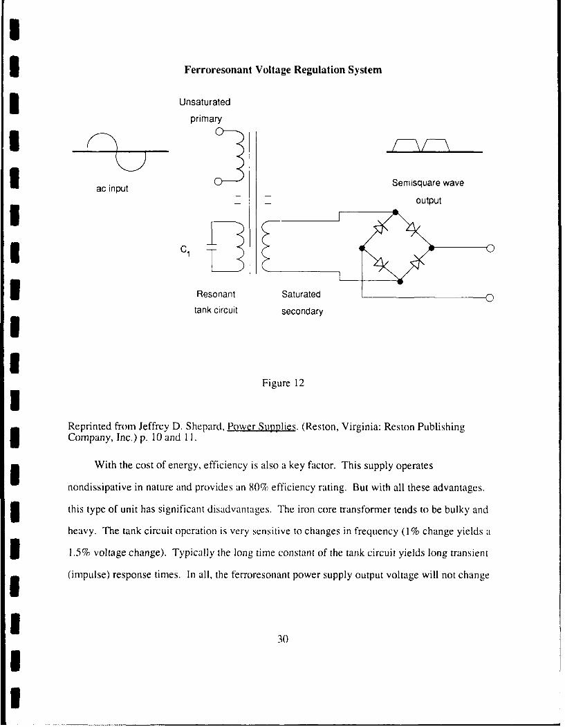
IFerroresonant Voltage Regulation System
3 Unsaturated
primary
I ac input Semisquare wave
I _output
, 1C
3 Resonant Saturated 0tank circuit secondaryI
IFigure 12I
Reprinted from Jeffrey D. Shepard, Power Supplies. (Reston, Virginia: Reston PublishingCompany, Inc.) p. 10 and 11.
With the cost of energy, efficiency is also a key factor. This supply operates
nondissipative in nature and provides an 80% efficiency rating. But with all these advantages.
3 this type of unit has significant disadvantages. The iron core transformer tends to be bulky and
heavy. The tank circuit operation is very sensitive to changes in frequency (1% change yields a
31.5% voltage change). Typically the long time constant of the tank circuit yields long transient
(impulse) response times. In all, the ferroresonant power supply output voltage will not change
330
IU

given a ± 15% change in the input voltage but is seldom used in today's electronics. [39:11-121
While the ferroresonant power supply is slow to react to changing line conditions, the
linear power supply can react to changes in 10 to 50 microseconds (ps). Unfortunately, the
3 linear power supply is very inefficient (30% - 40%). For the power supply to provide a regulated
five volts output, the transformer must provide a six to seven volts output. The difference
3 between the transformer output and the power supply's regulated output is called "head room".
The difference is required to ensure the power supply's full load operation even during a low
I input line voltage (maximum input line voltage ± 10%). [39:12-131
3 Regulation in the linear power supply is accomplished after rectification. The output
voltage is compared to a reference voltage. If the output voltage changes, either due to load
3 condition or changes in input conditions, the change(s) is immediately detected (10 to 50 gsec)
and the base current of the transistor is altered to compensate for the changed concition(s).
1 139:12-131 See Figure 13.
3 Switching regulation employs many of the superior qualities of the ferroresonant and linear
power supplies. Like the ferroresonant system, the switching system is nondissipative with an
3efficiency typically in the neighborhood of 70% to 80%. The switching system uses an active
feedback to control regulation like the linear system. For the ferroresonant system, regulation
U occurs within the transformer, while linear system regulation occurs after the secondary of the
transformer and rectification. Regulation for the switching power supply can occur on the
primary side of the transformer (Pulse-Width Modulation, PWM) or the secondary side of the
3 transformer (Phase-Control Modulation, PCM). [39:13-15] These differences and similarities to
the previously discussed power supplies make the switching power supply the preferred power
3 supply choice for today's electronics.
3
I

Linear Power Supply System
* Pass transistor
3 ac input Regulated
Control do output
* Figure 13
3 Reprinted from Jeffrey D. Shepard, Power Supplies. (Reston, Virginia: Reston PublishingCompany, Inc.) p. 13.
3 The switching system, like the linear system, compares the dc output voltage with a
reference voltage. In the switching case, the control system selects the amount of time the
switching transistor (Pulse-width modulation) or the silicon-controlled rectifiers (SCR)
(Phase-control modulation) are on or off. If ratio of on-time to off-time increases, the output
voltage increases. The ratio of on-time to off-time can be varied by the controller to maintain a
3 constant output with a varying input. Operation at frequencies between 20 and 50 kHz
eliminates any possible audible noise and allows for the use of smaller transformer and filter
systems (usually one-third to one-sixth the size of similar linear or ferroresonant power systems).
3 However, operation of the switching power supply at these frequencies causes the unit to
generate significant amounts of unwanted electromagnetic interference (EMI) that must be dealt
I
1 32

with. [39:13-16]
The advantages of phase-control modulation are low cost, high efficiency and outstanding
reliability. But, even with all of these advantages, the pulse-control modulation system is rarely
3 used because of its disadvangtages. The disadvantages are less energy storage capacity than the
pulse-width modulation switchers, higher noise (up to 500 millivolts peak to peak), and poor
3 transient response and regulation characteristics (requires several ac line cycles to respond to
input or output changes like the ferroresonant system). [39:14-151 See Figure 14 for an example
Iof pulse-width modulation and Figure 15 for an example of phase-control modulation.
ISwitching Power Supply (Pulse-width modulation)
a c in p u tS w t h n
0t Regulated
dc outputIoI3 Figure 14
I Reprinted from Jeffrey D. Shepard, Power Supplies. (Reston, Virginia: Reston PublishingCompany, Inc.) p. 14.
II 33
i
I

U
* 2.5 Filters
No matter what form of regulation is used, brute force, ferroresonance, linear, or switching
systems, the regulated source of power still experiences fluctuations. A filter stage can be placed
3 between the load and the regulation/rectification power system to smooth the power fluctuations
and provide a more constant dc output level. This filter is very important in the control of spikes
I and transients.
USwitching Power Supply (Phase-control modulation)I
3 ac inputRegulated
3 dc output
I o0
ControlII Figure 15
I Reprinted from Jeffrey D. Shepard, Power Supplies. (Reston, Virginia: Reston PublishingCompany, Inc.) p. 15.
3 The simplest filtering stage is to place a capacitor across the output of the regulation/
rectification power system (also in parallel with the load) or an inductor in series with the
I34
II

regulation/rectification power system and the load. In either case, the capacitor or inductor acts
as a reservoir, absorbing or discharging energy with the net effect of a constara dc voltage
applied across the load. [39:16-171 Inductors block high frequency changes while capacitors
3 can shunt the high frequency changes from the load (the computer). [31:6] Figure 16 is an
example of capacitive filtering and Figure 17 is an example of inductive filtering.
3 For today's microprocessor systems a single inductor (a magnetic coil with low dc
resistance, voltage device) or capacitor (current device) cannot achieve a high quality dc output.
By combining the qualities of the capacitor and the inductor, a LC filtering system can provide a
3 high quality dc output. By adding a capacitor (in parallel with the load) or an inductor (in series
with the load), the filtering network can be as complex as required to obtain the desired dc
3 voltage output for load and input voltage sensitivity. [39:16-17] Inductors inherently experience
capacitances between the windings. These capacitances allow very high frequency signals to
I pass through. On the other hand, foil capacitors have inherent series inductance. Since
capacitors are placed in parallel with the load (computer), this would tend to block high
frequency signals and pass the effects on to the load. Ceramic capacitors (low inductance pulse)
3do a better job of removing fast rise-time transients. [31:6-71 Figure 18 is an example of an
inductive-capacitive (LC) filtering system.
3II
I
I35
1I

U
Simple Capacitive Filtering System
Regulated Filtereddc 0IFlee3 dc output
IFigure 16
Reprinted from Jeffrey D. Shepard, Power Supplies. (Reston, Virginia: Reston PublishingCompany, Inc.) p. 16.
I Simple Inductor Filtering System
oI
I Regulated Load Filtered
3 dc 0 dc output
IFigure 17
Reprinted from Jeffrey D. Shepard, Power Supplies. (Reston, Virginia: Reston PublishingCompany, Inc.) p. 17.
I[ 36
II

U
Inductor-Capacitive (LC) Filtering System
I _
Regulated Filtered
dc dc output
I
i Figure 18
Reprinted from Jeffrey D. Shepard, Power Supplies. (Reston, Virginia: Reston Publishing3 Company, Inc.) p. 17.
1 P3 Methods and Devices
3.1 Power Conditioning
3 Many factors must be considered to provide acceptable power for microprocessor
equipment. Total power protection is impossible to obtain. Thus, the goal is to minimize,
3 reduce, or increase power aberrations to an acceptable standard. James D. Vail pointed out the
importance of the interface between the utility company, buildings, power-protection devices,
and microprocessor load. These units must work in harmony or the goal to prevent damage and
I1 37
II

improve up time will not be met. James D. Vail provided the following four requirements that
power-protection alternatives must meet to ensure appropriate interface between the electrical
environment and microprocessor load;
1"1. Reduce all electrical noise levels to less than 10 volts of line noise(also referred to as normal-mode noise - between line and neutral), and lessthan 1/2 volt of ground noise (or common-mode noise - between line andneutral - in relation to ground). Theae are maximum levels tolerable toprevent disruption, degradation and destruction of medical electroniclogic."
"2. A clean, single-point ground. A noise-free ground reference preventsground noise and ground loops which can occur when interconnected piecesof equipment are at different ground potentials."
"3. A low-impedance source of power that will allow the switching powersupply to effectively draw current from the line."
"4. Low-leakage current specifications in order to maximize patient safey.Leakage current is any current which may be conveyed to the patient bythe exposed metal parts of a product." 144:95]
The basic solution to power problems is divided into two areas, internal protection and
external protection on a particular equipment item. Internal protection comes from the
I equipment's manufacturer. The user/operator has little or no control over this area. During the
equipment design phase, the manufacturer designs or uses an "off the shelf' power supply that
provides a particular minimal output, given various levels of input. As shown, a power supply is
3 typically composed of transformer, rectifier, LC filter, and voltage regulator stages. These stage.,,
combine to prov'de an internal protection system for the microprocessor unit. [ 11: 13, 14:145]
3 A LC filtering cic uit can provide "ride-through" protection. A typical power supply can
continue providing power for twenty (20) to twenty-five (25) milliseconds after total loss of
power. The load at the time of power loss and the inherent characteristics of the tiltering system
3 determine the length of "ride-through". 13 1:51
38

I
I A properly designed power supply should have an input window of ± 10 percent (104 to
126 volts for 115 volts system). As long as the voltage remains within the input power window,
the microprocessor system will operate correctly. If the voltage drops below the input power
3window for a period of time that exceeds the "ride-through" period, the power supply will not
provide sufficient dc voltage and the microprocessor system will malfunction. [31:5] The
3 internal protection system is primarily effective against short periods of sags or surge conditions.
A well designed power supply system goes a long way in minimizing power aberration
I problems.
External solutions to power aberration problems provide after the fact solutions. Power
aberrations travel in the utility system at close to the speed of light. All electronic devices have a
3 reaction time called delay time. Delay time in semiconductors is frequently the time required to
create a depletion region (develop a capacitance charge) and the time for charged particles to
I cross the depletion region. In other words, it is the time required for the device to turn on. For a
g Metal-Oxide Varister (MOV), this time is typically 5 nanoseconds (5 x 10⁹ seconds). During
this 5 nanoseconds time period, a power aberration --an travel four (4) to five (5) feet. By placing
protective devices externally on the equipment, the protective devices have time to turn on and
react to the disturbance. By placing the protective devices before the equipment, at the outlet or
3 service panel, the intervening wire and typically six (6) foot power cord provides time for the
protective device to react. Externally applied protective devices work better than if the same
device was applied internally because of the reaction time provided by the intervening wire.
3 [21:1451
3I
| 39
II

I
3.1.1 Types of Power Conditioning
Howard C. Cooper recommends the following steps for selecting appropriate power
conditioning:
1 "1. Consider amount and type of conditioning already built into both theelectrical system and into the electronic or computer devices."
"2. Select the device or devices that will most cost-effectively remove orcondition the remaining problem..." [ 11:5-61
The primary means of accomplishing power conditioning are to ensure proper grounding
3 and the use of a suppression network, or voltage stabilizer, and voltage regulating transformers.
An isolation transformer can reject common-mode problems, but can do little against
1normal-mode problems. A surge suppressor is effective against common-mode and
normal-mode problems to a maximum peak level and is ineffective after the peak level. Line
and noise regulation, and to a limited extent, common-mode is provided by ferroresonant
systems. At the same time, ferroresonant systems can aggravate sag and short power failure
problems. A Radio Frequency Interference (RFI) filter is effective against normal-mode,
common-mode and low frequency noise but has little affect against spikes or transients. [6:1431
Figure 1 illustrates that spikes are the most common power aberrations encountered. A
suppression network (crowbar - virtually short to ground or Transient Voltage Surge Suppressor
3 (TVSSs) - removes spikes or transients above a certain threshold level) can protect (limit
damage) equipment from circuit board failure, software glitching and system lock-up. Power
3 conditioning techniques smooth the distortions riding on the sine wave. Suppression does not
smooth the distortions but clamps the transient(s) or spike(s) at a preset peak voltage. The
suppression device can deal with the excess energy from the transient(s) or spike(s) in several
ways. The energy can be shunted to ground or clamp the voltage between the "hot" and
I40
II

I
"neutral" to stay within a preset limit. With the preset limit case, the excess energy is dissipated
as heat within the suppressor and along the neutral side of the power line. Examples of simple
suppression devices are constant-voltage devices (Metal-Oxide Varister's (MOV's), zeners and
I avalanche diodes, Silicon Control Rectifiers (SCR's), Triac's and Switching Darlingtons) and
crowbar or short current devices (Arc Gaps, Gas tubes, and Thyristors). [11:6-7;151
3 The next step up in suppression devices is networks. Howard C. Cooper compares
suppression networks to car shock absorbers. Suppression networks average or smooth the
power aberrations an equipment unit experiences. Howard C. Cooper provides the following key
3 capabilities or specifications for suppression networks:
"1. Speed or response time should be less than 1 nanosecond. Slowersuppression devices will allow transient energy to pass by before they are ableto respond".
"2. Energy absorbing capability for maximum transient current should be15,000 amps for 20 microseconds."
"3. Clamping voltage should be 10 to 20 percent above nominal peak voltage(140 V RMS or 200 V Peak for nominal 120 V.A.C.)."
"4. RF traps and voltage smoothing filters should be incorporated into the* network of high speed and high energy suppressors to kill harmonic ringing
*that is sometimes generated as the transient is clipped off to a low amplitudesquare wave." [11:71I
Zeners and avalanche diodes pass a predictable current and voltage in the forward
I direction. High energy spikes or transients contain sufficient energy in the form of heat to
destroy the diode. Initially, the diode fails as a short and then burns open. The reaction time of
diodes to power aberrations is in the nanosecond range. [6:144]
3 Metal-oxide varistors (MOV's) are symmetrical (bipolar) semiconductor devices. These
devices are voltage dependent with a nonlinear resistance variable. When a low voltage is
II
41
I
I applied across the metal-oxide varistor, the device displays a high resistance and thus passes
little to no current. During an overvoltage condition, the metal-oxide varistor resistance
decreases greatly and shunts the current from the load. Metal-oxide varistors can handle up to
5 300joules with response in the nanosecond range. [4:147, 6:144]
Gas tubes are high-energy devices but with slow response times. With each spike,
3 transient or surge, a portion of the gas with the tube is consumed. Frequent spikes, transients, or
surges (above maximum continuous operating voltage) will significantly shorten the tube's life
I expectancy. [22:303, 40:S-14]
3 Hugh 0. Nash, Jr. recommends health care facilities use silicon avalanche diodes that can
pass IEEE (ANSI C62.41) 6KV pulse with 1.2 microsecond rise time for transient voltage surge
Ssuppressors. Where the exposure to lightning surges is high Hugh 0. Nash, Jr., recommends
using metal oxide varisters (MOV) at the service entrance(s) to handle the increased energy of
3 the power aberrations. The suppressor includes a filter that removes the remnants of the
3oscillatory ring wave after clipping. [31:7-8]
The Transient Voltage Surge suppressor comes in two types: 1) series or 2) parallel.
3Series connected suppressors are more effective but are significantly more expensive. The
inductor(s) of the series suppressors must be capable of handling 2,000 amps service for a typical
5 200-bed health care facility. Because of the high current rating required for series suppressors,
they are seldom used on service entrances or large feeder lines. Series suppressors are very
effective in controlling the power aberrations created by the health care facilities' solid state
5 controllers and computer switching mode power supplies. 131:7-81
Ferroresonant transformer systems have been the old standby for voltage regulated
transformers. The ferroresonant transformer provides excellent normal-mode and
common-mode rejection while correcting voltage irregularities of ± 15% of nominal line voltage
42

I
3 to within ± 3% of the nominal line voltage. The switching power supplies frequently used in
today's medical equipment provide excellent voltage regulation. In fact, a switching and
ferroresonant transformer system can interfere with each other's operations unless they are
3 compatible. Ferroresonant transformers tend to be unstable (oscillate) if the medical system
equipment exhibits substantial load changes and/or variations. Line notches (can be experienced
3during test of the emergency generator) affect the ferroresonant system's ability to deliver power.
A ferroresonant transformer must recharge the tank following the notch which extends the
recovery time. The recovery time can extend through the microprocessor's "ride-through"
3 power supply specification leading to a system crash. [44:97-981
3 3.1.2 Sequence of Power Conditioning Steps
Frequently manufacturers require certain electronic or microprocessor equipment be
I installed on a dedicated line. A dedicated line is a separate line directly from a distribution panel
i to the site of the electronic or microprocessor equipment. No other piece of equipment is on tnis
lin . A dedicated line is neither a power conditioning or power protection device. Any power
3 aberration the distribution panel experiences will be transmitted to the dedicated line also. The
primary advantage of a dedicated line is the dedicated ground from the distribution panel
5 (source) to the equipment item (load). This improved ground helps to avoid common-mode
problems and improve operation of power and/or conditioning devices. The load experiences a
stable voltage level because of the absence of other loads. Long dedicated runs increase the
3 probability of noise on the line. The increased wire length increases the wire's impedance which
in turn increases the probability the computer's power supply will generate noise on the
1 dedicated line. [5:84, 11:7, 44:95-961 This noise could be transmitted to other loads connected
to the same distribution panel.
43
I

I3 A dedicated power line improves grounding. A second approach to grounding problems is
the Power Distribution System (PDS). This distribution system replaces the entire computer's
power system, (wire, circuit breakers, transformer, etc). The system provides a quality ground
and limited spike/transient suppression. The primary advantages are improved computer
operation by quality ground, enhanced ability to interface with the building's power system, and
5 increased flexibility to change. The power connections under the Power Distribution System are
not in rigid conduit with conventional wiring but are flexible and will allow movement (to a
I limited extent) of the computer. [7:351
3 Before a health care facility installs power conditioning devices they should consider the
following factors. The FCC requires electrical power companies to regulate power within five
3 (5) percent high and ten (10) percent low of nominal line voltage. Step down transformers used
to convert power to the required user levels also reduce the effects of power aberrations by fifty
I (50) to seventy (70) decibels. Electronic equipment dc power supplies contain power protection
elements. [ 11:7-81 This built in power protection should be considered before purchasing
additional power protection.
3 There are two primary approaches "., .clcing power conditioning equipment. The first
approach follows the philosophy "if it ain't broke, don'tfix it". This approach follows a wait
3 and see attitude. If a power problem occurs, then fix it. The user(s) and the clinical engineering
department must consider the cost and probability of physical damage to the equipment, loss of
operating time, and the probability of catastrophic data loss. While you are experimenting, be
3 sure the cost and risk is acceptable. 131:21
The second approach selects power conditioning equipment based on the type of
3 equipment to be protected and based on the history of power line aberrations. For example, if a
history of frequent voltage changes occur and the new equipment is sensitive to voltage
44
I

I
fluctuations, then a voltage regulator is in order. If the health care facility is located in an area of
frequent lightning storms or spikes/transients, a transient suppressor would be advisable.
131:2-3]
3 A site survey conducted with a power line analyzer before installation of new equipment
has become fairly common. Hugh 0. Nash, Jr., recommends installing a high quality surge
suppressor on the power line before the site survey. Even if the site survey indicates further
power protection is required, the surge suppressor can help protect the new equipment and power
Icondition/protection equipment. 131:2-31
3Howard C. Cooper recommends the following cost-effective implementation step for
power protection devices:
1 "1. Check electrical wiring and grounding for poor contacts, resistivebreakers, and poor grounding..."
1 "2. Install transient suppression networks at the circuit breaker cabinet andat the equipment ac powerentrance (physically at 120 V.A.C. or 208 V.A.C.gas it enters equipment dc power supplies)..."
"3. Install a power conditioning, regulating transformer between the lineand load transient suppressors. Make sure the kilowatt volts x amps rating3 is about 20 percent over the actual peak Kilowatt demand of the system..."
"4. With a good power conditioning transformer between line and loadtransient suppressors, the only remaining disturbances that could causeproblems would be long-duration brownouts or actual blackouts. Thesewill never cause hardware orcircuit board failure. However, if they happenfrequently enough and actually cause disruptive failures or loss of data thatare costly to system operation or liability, then an Uninterruptible PowerSource, (U.P.S.) system, voltage synthesizer, or motor generator will haveto be cost justified..."
3 "5. Before going from step 2 to step 3, and before going from step 3 tostep 4, a complete check should be made for loose circuits boards or loosecable connections. Loose or oxidized connections within systems can causesymptoms that look like power disturbances. Also, particular disruptionsthat occur every afternoon at about the same time, could be caused bytransients from elevators, chillers, or large equipment switched on at thattime, or the cause could be heat build-up, which is always worse in theafternoon." 111:8-91
445I
I

I
Howard C. Cooper's power protection sequence provides a cost effective sequence for
reducing the effects of power aberrations. He suggests you do not overlook the other causes of
electronic failure such as heat, vibration, oxidation, and dirt build up. Following these simple
3steps can reduce the cost of overhead and at the same time increase the system's reliability (up
time). [11:91I3.2 Power Protection
IPower protection devices (Uninterruptible Power Supply System U.P.S. ) are the only
3 devices available to ensure continued operation (no-break power) even during a complete loss of
power. As stated previously, 'ower companies only consider a lack of power lasting over three
3(3) minutes as a power failure. An outage greater than 4 milliseconds can cause a computer
system to "crash". [5:84-85] The loss of power (blackout/brownout condition) can cause loss of
I data, but is typically not destructive to the computer's hardware. The surge that accompanies the
return of commercial ac power can and often times is destructive to the computer's hardware.
111:51
The intent of an U.P.S. is to provide total power protection against both overvoltage and
undervoltage conditions. The primary reasons for using an U.P.S. are 1) clean uninterrupted
3 power (primarily for data processing), 2) safety and security (provides emergency lighting,
maintains operation of life support equipment, and continues alarm-system operation), and 3)
prevents loss of production time and materials (continues a manufacturing operation that cannot
3 be restarted "midstream"). An U.P.S. has three basic applications: 1) bridge the gap for
motor-generator (provides power to the load after commercial ac power failure and before the
motor-generator has stabilized, 2) provides time for an orderly shutdown (sequence shutdown
rather than a system "crash"), and 3) continue operation until commercial ac power returns.
446
!I

I
U 15:86-871
The typical U.P.S. is called a reverse-transfer system. The system is composed of four
basic components: 1) rectifier/charger, 2) battery bank, 3) inverter, and 4) bypass/transfer
5switch. Under normal conditions, commercial ac line power is provided to the first stage
rectifier/charger which in turn maintains the battery bank charge and power to the inverter. The
inverter provides power to the load (computer). In the event of a commercial ac power
failure/interruption, the battery bank (continuously provides power to the inverter) provides
Ipower to the inverter and continues normal operation of the load (computer) without power
3 interruption. To provide redundancy, the bypass/transfer switch (as long as commercial ac
power is available) provides protection to the load in the event of an inverter failure or if the load
3 demands a high influx of power. The bypass/transfer switch can automatically connect the load
directly to commercial ac power. Once the inverter can provide acceptable power, the
I bypass/transfer switch can be manually reset restoring the load to U.P.S. power. [5:85-86,
126:441 See Figure 19.
Correct tolerance parameters are important for the adequate operation of an U.P.S. . For
5 the rectifier/charger stage, the following parameters are important: 1) ac walk-in feature, 2)
battery recovery time, 3) input filter systems, and 4) input voltage tolerance. AC walk-in
I feature considers the gradual application of commercial ac power to the load (computer) during
periods of high power demand (load startup conditions or return of commercial ac power after a
power failure). This feature limits current demand on the inverter stage and reduces the
5 possibility of blowing line fuses or tripping other protective devices. [5:871
After a power failure, the rectifier must provide power to the load and recharge the battery
3 bank. The time required to recharge the batteries is frequently expressed relative to the discharge
time but, in some cases, manufacturers' specifications call for a minimum recharge time
I47
!U

I
I (typically 8 hours). [5:84 and 871 Remember, 50% of power failures last six (6) seconds or less.
f[5:84] A recharge time of eight (8) hours for a two (2) minute power failure could lead to
problems if a series of short term power failures occur. Most manufacturers specify an eight (8)
to fifteen (15) factor times the discharge period is required to recover the battery bank. [5:84 and
871I3Block Diagram of an Uninterruptible Power Supply System (U.P.S.)
Iac power line
SRectifier/Charger Inverter Transfer Switch
ac dc ,,
I j dc a / c_I /I
I Figure 19
IReprinted from Richard Caprigno and Gurcharn Dang, "Uninterruptible Power Supply Systems."3 Medical Electronics, October, 1983, p. 85.
Line filter(s) are placed on the commercial ac power line prior to the rectifier/charger to
Ireduce or minimize power aberrations (harmonic feedback) the U.P.S. may place on the
commercial ac power line. This prevents the U.P.S. from interfering with the operation of other
I48
II
I
loads on the same ac line or distribution panel. [5:87]
The input voltage tolerance is a very significant tolerance. This specification reflects the
range of commercial ac power inputs the U.P.S.'s rectifier can accept to power the load and still
charge the battery bank. Small U.P.S.'s (below 15 kVA) can continue to accept commercial ac
power to 20% of nominal commercial ac power line, while larger U.P.S.'s accept commercial ac
power to 15% of nominal commercial ac power line. This tolerance is particularly important if
an U.P.S. is called upon to provide power during a blackout condition when the blackout follows
I an extended brownout period. The lower nominal ac voltage during the brownout condition
preduces the battery bank charge affecting its ability to deliver power during the blackout period.
[5:87]
3 The battery bank provides the power during periods of low nominal line voltage or no
voltage conditions. The battery bank is divided into two groups: 1) wet-cell, and 2) gelled-cell.
I The wet-cell group is divided into flooded and maintenance-free batteries. Flooded style
batteries have removeable vented caps. This provides the ability to checked the electrolyte and
make corrections as needed. Wet-cell batteries release noxious and explosive gases during
charging. The vented cap allows the gases (oxygen and hydrogen) produced during charging to
escape. Therefore, the air in the battery room must be changed at least daily. The batteries must
5 be situated within the U.P.S.'s room to allow servicing. Maintenance-free batteries are
high-pressure sealed. Thus the gases (oxygen and hydrogen) produced during charging are
contained within the battery and allowed to form water. Nickel-cadmium and lead-acid batteries
compose the wet-cell battery category. The lead-acid batteries can be lead-calcium or
lead-antimony. Lead-calcium batteries are preferred because they require less water, lower
5 maintenance, and a lower floating charge to maintain a full charge. [5:87-88, 26:44-46]
Gelled-cell batteries are considered nonmaintainable. The electrolyte is immobilized
449U
I

I
within a gel. The battery is a lead-acid design. This style of battery releases gases (oxygen and
hydrogen) like the flooded battery style. No provision is made to add water to replenish the
electrolyte. Therefore, the air in the battery room must be changed at least daily. This type of
3 battery construction is best for use in tight or confining areas. [5:88, 26:44-46]
The following basic safety precautions must be exercised and safety equipment present for
all battery rooms: posting and enforcing a no smoking policy, fire extinguisher, gloves, goggles,
and eye wash station or shower. Batteries perform best at 26°C ambient temperature. Higher
temperatures reduce battery life (increase rate of chemical reactions within cells which reduce
useful service life) and lower temperatures reduce battery efficiency (increase internal
resistance). [5:88, 26:47-481
3The inverter stage converts the dc power from the battery bank or rectifier back into
regulated ac power for the load. The desired output tolerance of the inverter stage is voltage
I regulation of± 5% or lower with a dynarnic regulation of± 10% or lower. This stage typically
employs pulse-width modulation (single-pulse, multiple-pulse, sinusoidal-pulse, or true
harmonic-reduction), impulse current-commutation, or ferroresonant-transformer techniques.
3 Impulse current-commutation controls the modulation by controlling the "on" time of SCR's.
This technique controls the output voltage and a dual phase-shifted transformer reduces the
5harmonic distortion (typically to less than 3%). This design provides excellent regulation, good
overload capabilities, and low output impedance. [5:88-891
For small U.P.S.'s (15-30kVA), a ferroresonant constant-voltage transformer (CVS)
provides acceptable ac power output. The size and the low operating efficiency of a
ferroresonant constant-voltage transformer system makes the system impractical for larger
systems. 15:88-891
The automatic bypass/transfer switch provides a measure of redundancy in the case of
550
I1

I
U.P.S. failure and commercial ac power available. The automatic bypass/transfer switch is a
solid-state switch that can accomplish a "no-break" power transition. Typically the switch can
automaticlly transfer (or manually for testing) to commercial ac power upon failure of the U.P.S.
3 and must be manually returned to U.P.S. power. It is important the inverter's output is
synchronized (phase-locked) with the commercial ac power line to ensure smooth transfer of the
3 load. 15:891 See section 5.2, Points to consider when purchasing an Uninterruptible Power
System (U.P.S.), for a detailed checklist of items to consider during purchasing of an
I Uninterruptible Power System.
3.3 Electromagnetic Interference (EMI) protection
Today's microprocessor equipment can operate (speed) within radio frequency ranges (10 -
30 kHz). Cost efficiency has led to the replacement of steel cabinets with plastic cabinets to
I contain microprocessor equipment that affords little, if any, protection from EMI or RFI. The
Federal Communication Commission (FCC) has developed EMI emission standards for
microprocessor systems. Technically, a subsystem can emit any amount of EMI, but once
generated the system must deal with the EMI produced and meet the standard as a system.
139:1261
I The FCC created two classes for EMI emissions: 1) class A for commercial, industrial and
business systems and 2) class B for residential or home system use. The FCC terms class A as a
'friendly", EMI-tolerant area, while class B as an "unfriendly", EMI-sensitive area. Therefore,
3 class B standard is more strict than class A requirements. [39:126] See Figure 20.
Verband Deutscher Elektrotechniker (VDE) is a West German organization responsible for
3 the testing of equipment for public safety similar to the United States organization UL. [39:168]
Currently, VDE's standards for EMI are more strict than the American Standards. Rather than
I 51
I

I
I separating by areas of use, VDE developed two equipment classes based on operating frequency.
Microprocessor systems operating above 10 kHz can generate significant amounts of EMI and
are covered by VDE 0871. VDE 0875 applies to equipment operating below 10 kHz. Jeffrey D.
Shepard believes the United States will eventually adopt the West German standards. 139:1271
See Figure 20.
The problems of EMI are divided into two basic groups: 1) conducting EMI and 2)
radiating EMI. The conduction of EMI into the power system and/or into the equipment item
must be dealt with. Filtering devices are able to remove sufficient amounts of EMI to prevent
interference with the microprocessor unit itself and the building's (utility) power system. The
two torms of conducting EMI are 1) differential-mode and 2) common-mode. Differential-mode
EMI (line-to-line) is an electrical potential across the ac lines (hot and neutral). The ac currents
produced by differential-mode EMI are 180 out of phase leading to the cancellation of the
I electromagnetic fields. Hence, the effects of differential-mode EMI are minor and attenuated
rapidly. [39:1281
Common-mode EMI is an electrical potential on ac lines (neutral and ground) but with
respect to ground. Because this form of EMI is with respect to ground, the radiating disturbance
can be effectively and rapidly conducted through the microprocessor unit itself and the
building's (utility) power system. Thus, this form of EMI disturbance is the primary source of
the problem. [39:1291
AC line filters can effectively control the amount of conducting EMI. One must consider
the following when evaluating a filter's performance: matching ac line impedance, matching
equipment impedance, smallest possible amount of attenuation at 60 Hz, and largest possible
amount of attenuation in the 10kHz to 30 MHz range. 139:131] Both the FCC and the VDE
have developed a 50 ohms line impedance stabilization network (LISN) to represent line
I52
II

impedance. The significant difference between the FCC and the VDE standards is the receiver
bandwidth within the LISN. The VDE standard calls for a 0.2 kHz bandwidth for frequencies
between 10 and 150 kHz while the FCC standard requires a I kHz bandwidth for lower
frequencies. The size of the bandwidth makes the FCC standard tougher. 139:1291 See Figure
21.
The number of sections a filter (the greater the number the greater the attenuation) contains
directly affects the filter's performance. A typical single section filter is able to attenuate 12 to
22 dB at 150 kHz and increases to 55 dB above 3 MHz. At the same time, a two section filter
can provide 70 dB of attenuation at frequencies below 500 kHz. Multisectional filters provide
greater attenuation than single or two section filters, 139:129] See Figure 22.
The best time to reduce the effects of radiating EMI is in the initial design stage of the
instrument (board development and component placement stage). To reduce radiated EMI the
II designer should use a grounded metallic cover surrounding the entire device, ground all shielded
i cables, use a single point ground method, and avoid using the metallic covers as return lines.
The case enclosing the device could also be constructed of a conductive composition material or
3 coated with nonconductive plastics. The design of the enclosure must avoid deep holes and
sharp corners. Sharp right angled corners couid contain sparse amounts of protective coating
which could act as antenna thus increasing the effect of radiating EMI. In addition, the electrical
paths must be kept as short as possible. The less EMI emitted by the individual components (the
system not individual components must meet EMI standards) the easier the designer's task.
139:129-1311 An effective grounding system and properly shaped enclosures are essential to
reduce radiating EMI.
I
53

!
U.S. and West German Standards for EMII100
1 80FCC Class A
> 60 VDE 0871A
40 VDE 0871Band
20 FCC Class B
20I
0 I I
1 0.1 1.0 10 100
Frequency, MHzII
Figure 20IReprinted from Jeffrey D. Shepard, Power Supplies. (Reston, Virginia: Reston PublishingCompany, Inc.) p. 125.
lIIlI
54
Ii

ILine Impedance Stabilization Network (LISN)
I To unit i To powerunder test 50 H 250 H o ure
ICI0.25 pF 8 WF 1.2 wF
II
IUI I, i-
1 lk 5fL 10 J-To 50 fL
receiver
I---- ------------------ - ------
i Figure 21
iReprinted from Jeffrey D. Shepard, Power Supplies. (Reston, Virginia: Reston PublishingCompany, Inc.) p. 129.
5iII
55
II

Sample filters that meet or exceed U. S. and West German standards for EMI
ac input Power supply
u0i
Single-section filter
ac input- Power supply
Two-section filter
ac input Power supply
3 Multisection filter
Ii Figure 22
Reprinted from Jeffrey D. Shepard, Power Supplies. (Reston, Virginia: Reston PublishingCompany, Inc.) p. 130.
II
I 56
II

I
3 3.4 Generator Transfer Switches
Each month health care facilities must operate the alternate (emergency) generator system
on load at operating temperature for thirty (30) minutes. [28:1023, 33:81 The horror stories are
3 countless during this test period. Some personnel turn off or unplug all microprocessor
equipment to avoid damage during generator testing. James D. Vail conducted a study at four
Midwest health care facilities to determine what actually happens electrically during an
emergency-generator test. His studies revealed a wide deviation in power quality during transfer
I and retransfer between the four health care facilities studied. But in all cases, a significant
number of impulses (transients or spikes) (common-mode and normal-mode) were experienced.
145:22-251
3 James D. Vail's study concluded the following three factors determine the amount of
difficulties a health care facility experiences during emergency-generator testing: 1) age of
I facility, 2) age of generator, and 3) type of transfer switch (conventional versus
make-before-break). The use of a make-before-break transfer switch generally resulted in no
voltage drop upon transfer or retransfer while the conventional switch often caused the voltage to
drop to zero. The best test results were obtained when the generator was brought up to speed,
synchronized to the line, and then transferred using a make-before-break transfer switch.
3 Typically, today's switching-powe, ,pplies can handle the voltage deviations experienced
during the emergency-generator test. If the microprocessor equipment cannot tolerate the
voltage drop or frequency deviations then an uninterruptible power system (U.P.S. ) is required.
3 145:25-291
II
I 57
II

I
* 3.5 Bottom Line
Cost is an important consideration when dealing with power aberration problems. A
clinical engineer must consider the opportunity costs when dealing with this type of problem.
3 No matter what course of direction he/she takes, there is a cost involved. If the clinical engineer
chooses not to add external power protection then he/she runs the risk that the equipment's
3 internal power protection is insufficient to protect the unit's hardware. If the clinical engineer
decides to use external power protection then he/she must consider the time value of money.
U The decision must consider the cost of spending money today versus the cost of spending money
in the future. For cxample, to spend $50,000 for an U.P.S. to prevent a loss of $5,000 (patient
safety not an overriding factor) woud not pass the test of time value of money. However,
3 spending $100 to $500 for a surge suppressor to prevent hardware damage of several thousand
dollars would pass the test of time value of money. 124:1-21
I Problem solving of power aberrations begins with the following steps:
1. Avoid problems in the beginning. Properly designed power supplies by themedical equipment manufacturers go a long way toward preventing powerproblems. If possible, review manufacturer's power supply specifications prior topurchase. Pay particular attention to the tolerance of input voltage, "ride-through"3 time, and response to IEEE surge waveforms. [21:145, 31:51
2. Ensure metal-oxide varistors (MOVs) surge arrestors are installed at service3 entrance. [3:10331
3. Establish a policy of installing a surge suppressor (series is best) at breaker boxfor sensitive computer equipment or computer equipment requiring extrasurge/spike/transient protection. The policy should include installation of a surgesuppressor prior to conducting a site survey. 131:31
4) If power problems occur, then analyze the problems to determine the types, and ifpossible, the sources of the problems.
a. Grounding problems. Consider the following possible solutions. See thefollowing tables for advantages/disadvantages.
II58
II

I3 a. Dedicated line. See table 3.
b. Isolated Transformer. See table 5.c. Power Distribution System (PDS). See table 6.d. Ferroresonant Transformer. See table 7.e. Low Impedance System. See table 8.
3 b. Transients/spikes/surges.
a. Suppressor or arrestors. See table 4.b. Electronic Filtering System.c. Regulation System. See table 7.d. U.P.S. See table 9.
c. Sags/brownouts/blackouts.
3 U.P.S. See table 9.
3 d. Generator transfer.
Ensure transfer switch is a make-before-break type. [44:25-28]
I e. Noise.
3 Add EMI or RFI filters depending on the type of noise and source.
IIIIII
| 59
II

U Dedicated Power Line
Method provides "good power" to sensitive equipment.
Estimate Equipment and Installation Costs - variesEstimate Maintenance Costs - noneEstimate Energy - none
I Advantages Disadvantages
1) More stable voltage 1) Adds to electrical noise and feeds noise2) Less chance other loads tripping CB back to breaker panel3) No other loads on feeder line 2) Longer the run the greater the electrical4) "Good" ground noise
3) Added installation cost4) Can provide a false sense of protection5) Must ensure dedicated line remainsdedicated as changes occur to the electricalsystemI
Table 3IInformation obtained from James D. Vail, "Protecting Digital Equipment from Power LineDisturbances, Part II-Power Protection Alternatives." Medical Electronics, February, 1988, pp.95-96 and Howard C. Cooper, "Power Conditioning to Protect Computers and ElectronicEquipment." American Society for Hospital Engineering of the American Hospital Association,June, 1984, p. 18.
IIII
II

I
Surge Suppressor
N Clips excessive voltages that might be present on the voltage sine wave.
Estimate Equipment and Installation Costs (RC or LC filters) - $100 to $500Estimate Maintenance Costs - noneEstimate Energy - none
U Advantages Disadvantages
1) Attenuates Noise 1) Allows spikes/transients to pass if they do
2) Clips excessive voltage not occur at the peak of the sine wave3) Low cost 2) Does little to reduce common-mode noise4) Transfers power well 3) Converts normal-mode noise into5) Effective against normal-mode problems common-mode noise by diverting
normal-mode to ground4) Offer must sacrifice common-mode noiserejection to have acceptable leakage currentsfor patient safetyI
Table 4UInformation obtained from James D. Vail, "Protecting Digital Equipment from Power LineDisturbances, Part II-Power Protection Alternatives." Medical Electronics, February, 1988, pp.96 and Howard C. Cooper, "Power Conditioning to Protect Computers and ElectronicEquipment." American Society for Hospital Engineering of the American Hospital Association,June, 1984, p. 18.
Metal-oxide Varistor - Can handle high energy but degrades over time.
Silicon avalanche diode - Reacts quickly but cannot handle high energy.
Gas tube - Crow-bar suppression techniques. Causes notching that some power supplies cannothandle leading to a system crash. 144:961
II
61
II

I
U Isolated Transformer
U Offers isolation between the primary and secondary windings. Reduces leakage current thusreducing the chance of electrical shock to patient. Provides excellent common- mode and3 ground-mode rejection.
Estimate Equipment and Installation Costs - $4,000Estimate Maintenance Costs - noneEstimate Energy - $600/year
3 Advantages Disadvantages
1) Reduces leakage current 1) High impedance forces switching power2) Excellent common-mode and supplies to draw higher current and thusnormal-mode noise rejection operate less efficiently3) Reliable 2) Allows components (one-point ground) to4) Relatively inexpensive to operate share noise due to high impedance of isolated
transformer3) High impedance leads to oversizing theisolation transformer relative to the load whichincreases costs of construction and operation
I Table 5
H Information obtained from James D. Vail, "Protecting Digital Equipment from Power LineDisturbances, Part II -Power Protection Alternatives." Medical Electronics, February, 1988, pp.96-97 and Howard C. Cooper, "Power Conditioning to Protect Computers and ElectronicEquipment." American Society for Hospital Engineering of the American Hospital Association,June, 1984, p. 18.
II
II
1 62
II

I
U Power Distribution System (PDS)
I Effective solution to complicated grounding requirements.
I Advantages Disadvantages
1) Portable and flexible 1) "You get what you pay for".2) Replaces all conventional wiring, conduit, 2) An incorrectly installed unit canand circuit breakers compromise the entire operation of the3) Provides some attenuation of spikes, computer systemtransients, and surges4) Provides excellent single point ground forthe computer system III
3 Table 6
Information obtained from Dennis M. Chambers, "An Overview of the Computer PowerProblem", Proceeding of the 1982 Control of Power Systems Conference, The Institute ofElectrical and Electronics Engineers, Inc., p. 35.
IIIIIIII
63
II

I
Ferroresonant Transformer
U Provides excellent common-mode and ground-mode rejection and voltage regulation. Mustensure the ferroresonant transformer system is compatible to the equipment system attached.
I Estimate Equipment and Installation Costs - $5,000Estimate Maintenance Costs - $800/yearEstimate Energy - $1,200/year
Advantages Disadvantages
1) Reduces leakage current I) If the ferroresonant system is not2) Excellent common-mode and compatible with equipment power supply cannormal-mode noise rejection cause the entire system to oscillate
2) If the system has substantial load variationor changes, then the ferroresonant system willcause the entire system to be unstable.Peripherals that switch on and off frequentlycan cause substantial load variation and makethe entire system unstable3) Line notches (typically experienced whenthe health care facility transfers to generator orvice versa) force the tank circuit to rechargereducing power provided to the equipmentitem. If time exceeds the equipment item"ride-through" specification the entire systemcould crash4) High impedance device that can lead toreflecting noise and cause switching powersupplies to work harder
* _5) Low efficiency ratings
3 Table 7
I Information obtained from James D. Vail, "Protecting Digital Equipment from Power LineDisturbances, Part II-Power Protcction Alternatives." Medical Electronics, February, 1988, pp.97-98 and Howard C. Cooper, "Power Conditioning to Protect Computers and ElectronicEquipment." American Society for Hospital Engineering of the American Hospital Association,June, 1984, p. 18.
IU 64
II
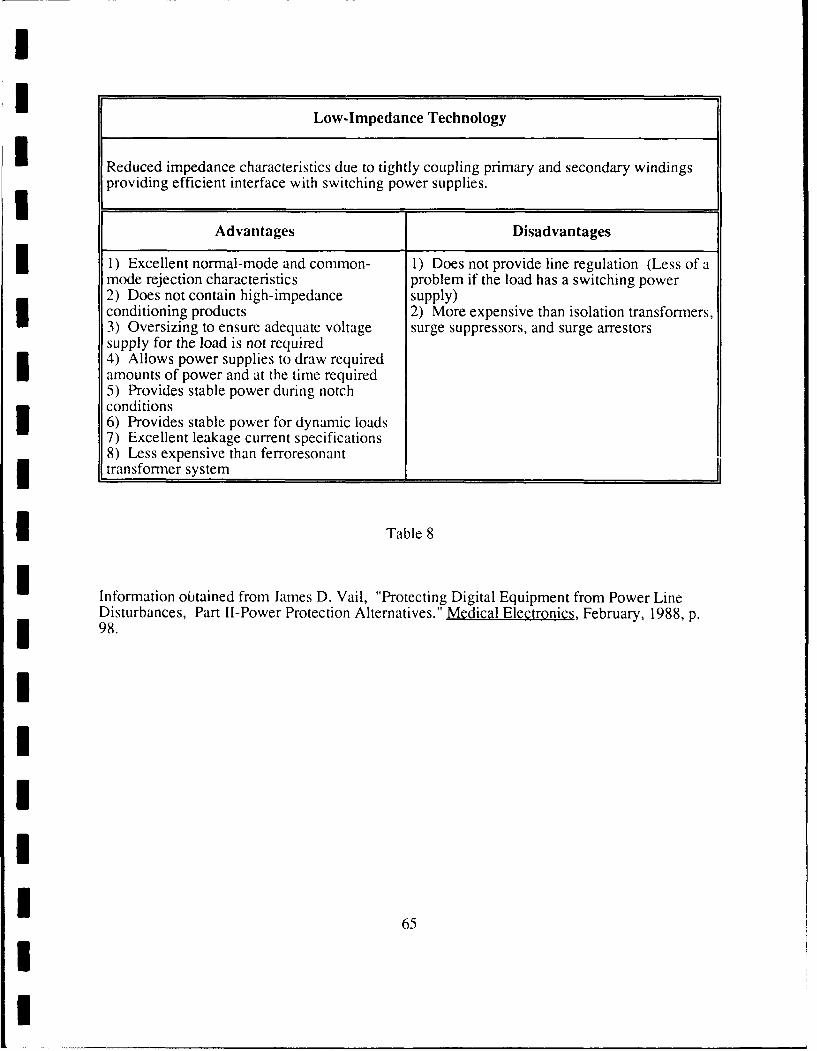
-- Low-Impedance Technology
1 Reduced impedance characteristics due to tightly coupling primary and secondary windings
providing efficient interface with switching power supplies.
Advantages Disadvantages
1) Excellent normal-mode and common- 1) Does not provide line regulation (Less of amode rejection characteristics problem if the load has a switching power2) Does not contain high-impedance supply)conditioning products 2) More expensive than isolation transformers,3) Oversizing to ensure adequate voltage surge suppressors, and surge arrestorssupply for the load is not required4) Allows power supplies to draw requiredamounts of power and at the time required5) Provides stable power during notchconditions6) Provides stable power for dynamic loads7) Excellent leakage current specifications8) Less expensive than ferroresonanttransformer system
i Table 8
i Information obtained from James D. Vail, "Protecting Digital Equipment from Power LineDisturbances, Part II-Power Protection Alternatives." Medical Electronics, February, 1988, p.
i 98.
IIII
I 65
II

I
IU.P.S.
N Used to prevent loss of data and hardware damage. Primarily used for blackout, brownout, orsag protection.
I Estimate Equipment and Installation Costs - $50,000 - $100,000motor-generator add additional $25,000 - $40,00
Estimate Maintenance Costs - $6,000/yearmotor-generator add additional $900/year
Estimate Energy - $5,000/yearmotor-generator add additional $3,000
Advantages Disadvantages
I 1) Provides power to computer systems 1) Expensive to obtain, operate and maintainduring blackout, brownout, or sag conditions 2) Could actually reduce reliability of thethus preventing loss of data and hardware computer systemdamage
I Table 9
IInformation obtained from James D. Vail, "Protecting Digital Equipment from Power LineDisturbances, Part II-Power Protection Alternatives." Medical Electronics, February, 1988, pp.98-99 and Howard C. Cooper, "Power Conditioning to Protect Computers and ElectronicEquipment." American Society for Hospital Engineering of the Ameican Hospital Association,June, 1984, p. 18.
3.6 Future or Not Too Distant Future
3 Chip manufacturers have developed integrated circuits that operate directly off ac power
lines. These chips, particularly in the low-current versions, reduce the scope of the power supply
required or eliminate the requirement totally. These chips can be connected anywhere without
3 regard to the quality of the line power and provide three dc outputs with current supplied up to
50 mA. The chips do not use transformers or inductors. 138:1311
II
66
II

One example is the HV- 1205 made by Harris Semiconductor. This chip connects to any
120 volt ac line and functions as a transformer, rectifier, filter, and regulator. This chip can
handle spikes/transients up to 6,000 volts and brownouts down to 30 volts ac (range of operation
30 to 132 volts rms). Input current can surge as high as 1.2 amps. This chip provides three
regulated dc outputs in the range of 5 to 25 volts dc and up to 50 mA. A battery or capacitor
ides power during sag/brownout/blackout conditions. 138:133-1341 See Figure 23 for a
block diagram of the chip.IBlock Diagram of a Power Supply IC (HV-1205)
Rectifier Current Switch Linear postregulator
RV , _bi V
I c
IFigure 23
Reprinted from Bob Pospisil, and Clayton Bennett, "New Chips Transform Power Conversion."Machine Design, September 7, 1989, volume 61, number 18, p. 133.
The integrated circuit power supply design includes an ac input filter network, power
supply IC HV-1205, energy storage network, and output conditioning network. The input filter
network limits startup current, clamps surge (surges, spikes, and transients) voltages, and filters
II
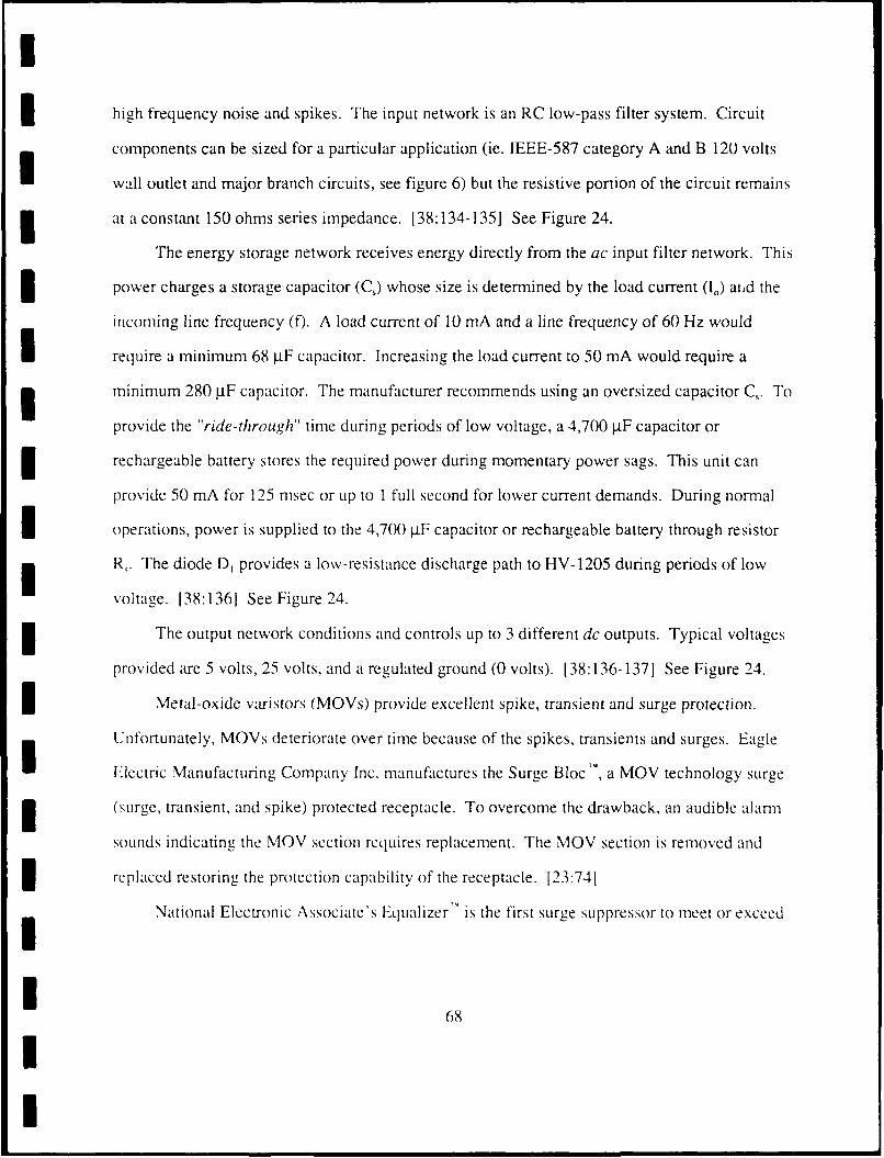
Ihigh frequency noise and spikes. The input network is an RC low-pass filter system. Circuit
components can be sized for a particular application (ie. IEEE-587 category A and B 120 volts
wall outlet and major branch circuits, see figure 6) but the resistive portion of the circuit remains
at a constant 150 ohms series impedance. 138:134-135] See Figure 24.
The energy storage network receives energy directly from the ac input filter network. This
power charges a storage capacitor (Cs) whose size is determined by the load current (I.) aihd the
incoming line frequency (f). A load current of 10 mA and a line frequency of 60 Hz would
I require a minimum 68 jiF capacitor. Increasing the load current to 50 mA would require a
minimum 280 p.F capacitor. The manufacturer recommends using an oversized capacitor C. To
provide the "ride-through" time during periods of low voltage, a 4,700 IF capacitor or
rechargeable battery stores the required power during momentary power sags. This unit can
provide 50 mA for 125 msec or Ip to I full second for lower current demands. During normal
I operations, power is supplied to the 4,700 jIF capacitor or rechargeable battery through resistor
R,. The diode D, provides a low-resistance discharge path to HV-1205 during periods of low
voltage. 138:136] See Figure 24.
The output network conditions and controls up to 3 different dc outputs. Typical voltages
provided are 5 volts, 25 volts, and a regulated ground (0 volts). 138:136-1371 See Figure 24.
Metal-oxide varistors (MOVs) provide excellent spike, transient and surge protection.
Unfortunately, MOVs deteriorate over time because of the spikes, transients and surges. Eagle
Electric Manufacturing Company Inc. manufactures the Surge Bloc", a MOV technology surge
(surge, transient, and spike) protected receptacle. To overcome the drawback, an audible alarn
sounds indicating the MOV section requires replacement. The MOV section is removed and
replaced restoring the protection capability of the receptacle. [23:741
National Electronic Associate's Equalizer" is the first surge suppressor to meet or exceed
68
UI

I
I military standards for surges. Using metallized crystalline ceramic structures, the Equalizerr"
appears to surges (spikes/transients/surges) as ground. The energy within the power aberration is
absorbed within the crystalline structure for temporary storage and then dissipated. Power
aberrations on the ground line are treated in a like manner. The unit switching time is 0.5 to 25
nanoseconds (nsec). 146:154]
For 120 V or 240 V single phase power systems, the EqualizerT, can handle a maximum
surge energy of 240 joules with a maximum current of 19,500 amps. For 3 phase 600 V service
I these maximums increase to 1,620 joules and 38,750 amps. The unit has built in redundancy
with two crystalline stages in parallel. If either (or both) crystalline stages fail, an audio alarm
responds. [46:1541
IIIIIIIII
I!6I

I Diagram of a Power Supply IC (HV-12O5)T "
ac input filter network Output conditioning network
I75C 7 5f~ _______
(2 W) (2 W) Otu
___20_V__output
5 Vfixed
30-132 0.05 10 pE utu
0o L L--------------------------------------gon
0~ 10or30VI I Output470 yE D, R (unregulated)
4,700 p Rechargeable
___ battery
__________troyti t- Unregulated
III Energy Storage network
Reprinted from Bob Pospisil, and Clayton Bennett, "New Chips Transform Power Conversion."UI Machine Desiarn, September 7, 1989, volume 6 1, number 18, p. 134.

I
m 4 Conclusion
Better power aberration term standardization would improve defining the problem. If
everyone (user, medical equipment manufacturer, power conditioning/protection equipment
3 manufacturer and utility company) used the same terminology it would improve communications
in the field of power aberrations. IEEE has formed a working group to improve power
aberration definitions and parameters. Cooperation among the various groups will go a long way
toward improving communication and diagnosing the various power aberration problems.
16:143, 31:3-41
In the past, power line monitors measured voltage threshold information about power
aberrations. The monitors could provide the time of the occurance and the type of the event (sag
or surge). If the duration and the rise time of the event could also be provided the possibility of
locating the origin of the power aberrations would be enhanced. Newer power line monitors are
I mbeginning to provide rise time and duration of power aberrations. [31:3-41
To achieve maximum effectiveness against power aberrations, one must match the solution
with the particular type of problem. The clinical engineer should not totally discount the internal
3 power protection within new microprocessor equipment. Remember, power aberrations travel
near the speed of light. 121:1451 A proper balance between internal and external power
m protection must be achieved. If the problem is grounding, a dedicated line or Power Distribution
System (PDS) should be used. If the problem is regulation, the clinical engineer should consider
using an U.P.S. or voltage regulation system. 17:351 Spikes, transients or surge problems can be
3 handled by a surge suppressor.
The use of money now or in the future has a particular cost. The clinical engineer must
I consider the time value of money. A selected course of action has an opportunity cost and a risk
associated with it. No action has the risk that the equipment will be damaged by power
1 71
I

aberration problems. The opportunity cost when adding external power protection is the benefit
or advantage lost by selecting external protection over another alternative. Engineering
I- economic considerations are important. Both sound engineering practices and fundamental
3 economic considerations are needed to develop a sound plan for power protection against power
aberrations. [14:66, 24:1-2]
Dedicated power lines for microprocessor equipment have certain advantages/
disadvantages. If a clinical engineer has determined his/her particular power aberration is beingT
I caused by a grounding problem, then a dedicated power line with its dedicated ground line could
just be the solution to the problem. Dedicated power lines are useful but a mandatory policy that
all microprocessor equipment be on a dedicated line is not required.
3 A more important consideration is what other devices are on the feeder circuit with the
microprocessor equipment. The placement of inductive motors on the same feeder circuit or
I very large inductive motors on the same circuit panel should be avoided. The use of low voltage
starter circuits on inductive motors helps to reduce the effects of power aberration problems
caused by these motors.
3 The clinical engineer should adopt a policy of placing surge suppression devices on feeder
circuit at the distribution panel. The use of series surge suppression devices is more effective but
3 more costly. By placing the surge suppression devices on microprocessor feeder circuit, the
clinical engineer has developed an engineering practice that is effective against 88.3% of the
typical power aberration problems experienced by a health care facility (See Figure 1). An
U.P.S. is required when patient safety or the economic cost justifies the use. An U.P.S. is not a
cure all solution to power aberration problems. They are very costly to purchase and maintain,
3 and increase utility costs. The U.P.S. is the solution to particular power aberration problems.
The clinical engineer should review the health care facility's emergency power system.
7I
!7
I

He/she should ensure the unit(s) can provide adequate kVa and that the transfer switch is of the
make-before-break type. A policy of synchronizing the generator with the commercial ac power
Iline voltage is important. These considerations will help to reduce the power aberrations
3 generated by the emergency power system.
The clinical engineer must understand that sound engineering practices along with proper
consideration of the time value of money are the key ingredients for controlling (minimizing)
power line aberrations. Knowing the source and type of power aberration allows for the proper
I corrective action and frequently at the least cost.
7IIIIIIIII
I 73
II

I
3 5 Appendix
i 5.1 List of Terms
Balance - A circuit is balanced when the current path to a common reference from a conductor issimilar to the current path of the other conductor. The voltage drops are equal andopposite polarity thus, zero volts develop across the input signal and do not causeinterference. Ratio of longitudinal voltage or current to the metallic voltage or current.[14:36-38]
Balance in Decibels (dB) - The balance/unbalance of equipment is often stated in decibels. Bydefinition, dB is the level of power reference to one milliwatt across an impedance of 600ohms. By definition, a decibel equals 10 log P/Pi where P0 equals output power and P,equals input power. Decibels using voltages are 20 log VJVI where V0 equals outputvoltage and Vi equals input voltage. [ 14:39-401
Blackout - Any power outage, even if the condition lasts for only a thousandth of a second.Power companies consider this a power failure only when the condition lasts for at leastthree (3) minutes. 50% of all blackouts (total loss of power) last six (6) seconds or less.15:841
Bonding - permanent joining of metallic parts of a structure to form an electrically conductivepath. The connection of the building assures electrical continuity of the building forground purposes. [14:691
Brownout - Condition when electric utilities reduce their nominal line voltage 10% to 15%because of demand during peak usage periods. [39:1571 Also see Sags. See Figure 3.
Commercial grade power - Power as received from utility company power lines. [ 11:2]
Common-Mode signal - measurement of electrical disturbance between neutral and groundwires. [42:259,45:251 Vcm = 1/2 (V1 + V2) [15:3821
Dedicated Line - separate power line running from the main distribution box to a particular pieceof equipment. This configuration avoids possible power aberrations caused by powerequipment on the same power line but, does not affect power aberrations that the maindistribution box experiences. An outstanding side effect provided by a dedicated line is adedicated ground which avoids many common-mode problems. 111:7]
IElectrical Protection - methods and devices used to control or reduce unwanted voltages andcurrents. Methods applied to the entire installation and the use of proven methodseliminate or reduce most undesireable longitudinal disturbances. Devices are considered
I supplements to the protection system [ 14:651Electromagnetic interference (EMI) - interfe.emce that travels electromagnetically through the air
and when crossing the path of any conductor (power line), induces a current of likefrequency and amplitude. 111:51 Typically, undesirable high-frequency noise (energy)created by switching transistors, output rectifiers, and zener diodes in switching powersupplies. This high-frequency noise can radiate or conduct on electrical lines from thesource to affect other electrical instruments. 139:1591 Also see Radio FrequencyInterference (RFI). See Figure 3.
74II

Ground-fault protection system - on a three phase power system, current is measured on allphases and neutral conductor to ensure sum of currents provided to the load equals the sumof the currents leaving the load returning to the transformer. If the two sums are not equal(amount of current difference and time period of current difference is established by thevalues set by the user) an appropriate breaker is tripped to prevent arcing faults known as"burn downs". 130:6-7, 47:613Impedance - Real part of impedance is resistance while imaginary part is reactance. [ 17:4261
Line Regulation - The deviation of the output voltage as the input voltage varies, with all otherfactors held constant. Term is expressed as the maximum percentage change in outputvoltage as the input voltage is varied over its range. [39:1621
Load Regulation - Deviation of the output voltage as the output's load changes from no load tofull load, with all other factors held constant. Expressed as a percent of the nominal dcoutput voltage. 139:1621
National Electrical Code (N.E.C.) - Code of rules and regulations as recommended by theNational Fire Protection Association and approved by the American National StandardsInstitute (ANSI). This code is frequently accepted as minimum standard for electricalinstallations by many political entities as their official code, or has been incorporated inwhole or in part in their official codes. 1 17:21113 National Electrical Safety Code - Rules prepared by the National Electrical Safety Codecommittee (secretariat held by the IEEE) and approved by the American NationalStandards Institute governing: (A) Methods of grounding, (B) Installation andmaintenance of electric-supply stations and equipment, (C) Installation and maintenanceof overhead supply and communication lines, (D) Installation and maintenance ofunderground and electric-supply and communication lines, (E) Operation ofelectric-supply and communication lines and equipment (Work Rules). 117:211-212]
Noise - Any high frequency signal modulating onto the voltage sine wave. FCC controls theamount of noise computer equipment can place onto power lines and into the environment.The noise is technically referred to as Electromagnetic Interference (EMI) or RadioFrequency Interference (RFI). [11:4-5] Also see Electromagnetic Interference and RadioFrequency Interference. See Figure 3.
Normal-Mode - measurement of electrical disturbance between live and neutral wires. [45:251
Opportunity Cost - The cost incurred in choosing a particular course of action. The cost is theloss in benefits and/or advantages of the choice not selected.
Overvoltages - last from a few to several ac cycles. (One ac cycle is 16.6 milliseconds, whereasa 20 microsecond transient is almost 1,000 times shorter.) During longer durations, thedisturbance produces enough heat to blow fuses, trip circuit breakers, and tend to bedestructive in nature. 111:51 See Figure 3.
Power Conditioning - All technologies and methods that help to clean and stabilize commercialac power. 111:21 Power line aberrations are "conditioned" (corrected/ smoothed-out).Power conditioning does not provide uninterruptibility (no protection against blackouts,extended periods of brownouts, sags, or total failure of the utility power system). 136:891
fPower Failure (electric power system) - Variation in electric power supply which causesunacceptable performance of the user's equipment. [ 17:5131
I 75II

I
Power Protection - protects (maintains) the quality and quantity of ac power line under all poweraberrations, even blackouts. Power protection is a broad term that encompasses powerconditioning. [36:891
Power System, emergency - An independent reserve source of electric energy that upon failureor outage of the normal pow-x source, automatically provides reliable electric powerwithin a specified time to critical devices and equipment. The failure of critical devicesand equipment to operate satisfactorily could jeopardize the health and safety of personnelor could result in damage to property. [ 17:520]
Power system, standby - An independent reserve source of electric energy that upon failure or3outage of the normal source, provides electric power of acceptable quality and quantity.The system allows the user's facility to continue satisfactory operation. [17:5201
Radio Frequency interference (RFI) - frequency range and nature of this noise. Covers aspectrum, from a few thousand cycles per second (5 KHz) to several hundred millioncycles per second (800 MHz). High frequency noise is induced onto the voltage sine waveby switching power supplies. 111:5, 39:1591 See Figure 3.
Regulated Power Supply - constant output voltage maintained by sensing output andautomatically compensating to minimize effects of input change. [39:9]
Risk (Expected Value) - Choosing a course of action involves risk. The future cannot bepredicted with absolute certainty. The clinical engineer must weigh theadvantages/disadvantages of each proposal and determine a probability of outcome. Basedon a determination of risk, he/she makes a selection of action to obtain the greatest returnof value. [24:2]
Sags - opposite of a surge. An undervoltage condition that lasts for approximately 2-3 cycles.Often called a "brownout" because it causes lights to dim for a half-second. Can causedisruptive malfunction if they are deep enough and long enough to starve dc powersupplies. Malfunction is often associated with the transients generated by the samedisturbance that caused the sag. As the power recovers, the voltage overshoots as ahigh-voltage transient. Brownouts are usually not destructive to hardware, but frequentlycause loss of data. 111:51 See Figure 3.
Sneak Current - a small current that is insufficient to trip circuit breakers or open fuses but given5 sufficient time can cause damage to equipment. [14:721Source impedance - the impedance at an input of a device or network as presented by a source of
energy. [17:4281
Sparkover - a discharge between electrodes of a measured gap, voltage control gap, or protectivedevice. A general meaning referring to surge arrestors. [17:14 and 8571
Spikes - occur in short bursts, or even singularly. Causes line voltage to rise sharply from a fewhundred to several thousand volts. Voltage frequently returns to normal in less than 8milliseconds (8 x 10-'). Spikes are frequently destructive to electronic equipment. Usuallycaused by extremely close lightning strikes or catastrophic disruptions within the powersystem. 111:31 See Figure 3.
7I 76
I

Static Electric - excess or deficiency of electrons on a surface. Two materials that are typicallypoor conductors or insulators come in contact and separate. The contact (friction) allows atransfer of electrons between the objects which establishes a difference in potential. Thisdifference in potential will attempt to equalize. [14:19-2 1]
Surge - This term is used to cover everything from overvoltage to transients. Typically refers toa broad spectrum of power disturbances. [ 11:51 The power aberration is superimposed onthe normal sinusoidal wave form and reference to ground. [14:71] A transient wave ofcurrent, potential or power in an electrical circuit. 117:9611 See Figure 3.
Time Value of Money - Concept takes into consideration the fact that the value of moneychanges over time. The use of money has a cost now and a different cost if used in thefuture. For example, the use of the money now prevents the same amount of money fromearning interest in a bank account. The cost is the lost interest. The use of the money on aparticular project prevents the use of the same money on a different project. The cost isthe benefit of the project that is not funded. [24:1]
Transients - fast spikes that last only a few microseconds but can rise to peak amplitudes ofseveral thousand volts within a few nanoseconds and decay away within severalmicroseconds. Transients can force or find their way through dc power supplies and intoelectronic circuits. This has become a problem only in recent years because previoustechnologies such as vacuum tubes and even transistors were not as susceptible orvulnerable to transients as integrated circuit (IC) technologies. [14:3-41 See Figure 3.
Transverse-Mode Rejection - refers to radiation-induced interferences. Has no significant effecton power distribution aberrations within a building. [6:1431
Uninterruptible Power Supply System (U.P.S.) - fast acting emergency power system thatprovides no break in power. 121:145, 5:84] Isolates the critical load and supplies clean,reliable, uninterrupted power while protecting the load from commercial poweraberrations. [36:891
I
I 77

I
5.2 Points to consider when purchasing an Uninterruptible Power System (U.P.S.)
1. General requirements:
a. Power Conditioning versus Power Protection.
1. Power conditioning protects (maintains) the quality and integrity of the powerline. Power conditioning does not provide protection against blackouts, brownouts,sags or total failure of electric power systems. [36:891
2. Power protection protects (maintains) the quality and integrity of the ac powerline. Power protection does provide protection against blackouts, brownouts, sags,or total failure of electric power system. [36:89]
3 b. On-line versus off-line (standby) power system.
1. Off-line (or standby) power system is inappropriate to protect microprocessortype equipment. A time lag will occur between loss of power and the switch toback-up power system. [9:26] Off-line U.P.S. operate only during power failure(notch conditions or undervoltage periods). Once a power failure is detected, theU.P.S. begin to provide power to the load. The U.P.S. unit provides protection only
I during periods of undervoltage or notch conditions. [44:98-99]
2. On-line power system provides full-time power protection by isolating thedependent load from power fluctuations. During brownout and blackout conditions
constant flow of power continues to the dependent load. [9:26] On-line U.P.S.converts ac to dc (battery) and then back to ac by using an inverter orengine-generator. Theoretically, this type of U.P.S. eliminates all types of power3 aberrations (noise, undervoltages, and overvoltages). [44:98-99]
2. How to choose between Power Conditioning versus Power Protection.
a. The worst possible power aberrations are total loss of power, insufficient powerfrom utility company (brownout condition) or sustained sags when the equipmentserviced by the ac line shuts down. [36:89] Ask yourself, what are the possible effects(safety/lost test results) on the patient? What are possible effects on the equipmenthardware?
b. Call or if possible visit users of protection/condition equipment. Compare problemsand review types of power processing (conditioning/protection) employed. [36:891
c. Discuss power protection/conditioning methods with the manufacturer of themicroprocessor medical equipment. Sometimes power conditioning techniques are notcompatible with the protected equipment. [31:101
3. How to specify the size of an U.P.S. system.
II
3 78
II

U
a. Determine kVA size rating for the system to be protected. If the protectedequipment includes computer equipment, be sure to include terminals, printer(s) andCPU for protection by the U.P.S. system. [5:89]
-I b. Consider start-up power requirements or possibly periods of high power demandrather than total normal operating power for kVA size rating. [5:89] This feature iscalled ac walk-in. Can the U.P.S. handle the start-up power requirements directly ormust it temporarily use commercial ac line power directly? [5:87]
c. Emergency lighting should be considered in total kVA size rating. If the U.P.S. isintended to carry the load only until an orderly shutdown can by accomplished, thenminimal lighting is required for safety. 15:89]
d. If possible, try to exclude air-conditioning or other things from the total kVA sizerating that can wait until a generator can take over or commercial power is restored.This will reduce the cost of the U.P.S. system. [5:89]
e. For maximum efficiency, an U.P.S. system should operate at or near full-loadrating. When operating at or near full-load rating the efficiency is approximately80-90% while only 65-70% when operating at 50% load rating. The lighter loadincreases heat production by the U.P.S. system. Special consideration should be givento expandability of the U.P.S. system and user's future power protection demands.Oversize of the U.P.S. system would allow future expansion at a cost of increased3 operation in the near term. [36:91]
f. Battery Recovery time. Avoid manufacturers that require a set minimum rechargingtime (typically 8 hours). Instead, select manufacturers that specify a recharge factor(typically 8-15) times the discharge period. [5:84 and 87]
4. How to specify the ac input service line.
a. The ac input service line should be sized for approximately one and one-half of theU.P.S. total kVA rating. Following a power failure (and the return to commercial/standby power), the U.P.S. system will draw power to satisfy the load and to recharge3 the batteries simultaneously. 15:89]
b. The following items/information are recommended to be placed in the contract:
1) User's service line voltage2) User's service line amperage3) User's service line frequency4) User's service line wire configuration5) Minimum power factors and harmonic feedback rectifier (U.P.S. 's) presents tooperator's ac line 15:891
3 _ 5. How to determine battery time requirements.
II 79
II

I
a. If required kVA reaches 50 and/or desired standby time required on batteriesexceeds 30 minutes, consider cost tradeoff by using an engine-generator. [5:89]
b. If an engine-generator is used, recommend the following order of equipment alongac lines:
1) engine-generator2) U.P.S. system3) load
This configuration allows the U.P.S. system to provide power regulation regardless ofI type of power available. [5:89]
6. How to select the input transfer switch to connect the generator output to ac line.
Sa. Numerous types of input transfer switches are available. This switch determines thelength of time a blackout must last before the generator starts-up. Remember theaverage blackout lasts less than six (6) seconds. [5:891
Ib. Make-before-break versus conventional transfer switch. Make-before-breaktransfer switch generally does not exhibit a voltage drop upon transfer or retransfer(during generator switching) while conventional switches often cause some type ofdrop. [45:251
7. Specifications to consider. Be sure to specify performance rather than designparameters. Try to use off-the-shelf equipment rather than modified equipment to meetyour contract specifications. [36:89-90] Example of specifications:
a. Computer equipment contains high-frequency switching power supplies that exhibita leading (capacitive) power factor. Will the U.P.S. equipment perform in all phaseloading and unbalance line conditions? [36:90]
3 b. Consider the maximum ambient temperature limit of the U.P.S. system.Compactness of the U.P.S. system may increase the cost of serviceability and/or reducethe maximum ambient temperature limit. Depending on the maximum ambienttemperature limit additional air conditioning for the U.P.S. system may be requiredthus reducing the efficiency of the U.P.S. system. 136:901
c. After use of the standby batteries, how quickly do they fully recharge? Does theU.P.S. system allow for future expansion? [36:90]
d. Given IEEE conditions, an U.P.S. should reduce all electrical noise levels to lessthan 10 volts normal-mode and less than 1/2 volts common-mode.
e. If the equipment item to be protected has a switching power supply, ensure the
3 U.P.S. will allow the equipment item to draw curreni as required.
f. Is the U.P.S. waveshape acceptabie to the load? 144:991
3 g. Ensure the system (U.P.S. and load) has a single-point ground. This will prevent a
I80
I

difference of potentials between different components. The single-point ground willprevent ground noise and ground loop,. 17:351
h. Ensure an automatic h vpas,,/ii . r , i. is ncluded. In the event of an U.P.S.failure, the load (conip :cr) co I"i r,, ,wtoml ..Dil connected directly to thecommercial ac po\,er liie en :in2, 11LI,s operation. Once the UJ.P.S. problem i1corrected. .he bypass/transftr switch will :-q'ire manual activation to return the load(comput,r) to tihc I L7 .S. . 5
I 8. Nlisconcep:., n t-o avoiM.
a. Thte more the ptectio ccss, the better the protection. Wrong! Increased costdoes .. m.n a of'tt:r chnec. ot c minating computer and electronic equipmentproblc;1is. i IL o0 is tO ac e r,!iable equipment operation at the lowest cost(equipment atio opcr'1rio) 'without power conditioning/protection overkill. 11:31
b. U.P.S. can provide a f,dse ,ense of security. If power reliability is 99% and theU.P.S. has a 99§,; reliability, then the system's new reliability is 98%. A decrease ofsystem reiiabilitv. 144:991I
II
II

I
5.3 Effects of 60 liz Current on Humans
ICurrcnt(mA) Effect___ _ __ _ _ __ _ __ _ _
ISensation of Shock
Muscle Control not lost
8 - 15 Painful ShockMuscle Control not lost
16- 50 Painful ShockMuscle Control lostBreathing becomes difficult
51 - 100 Very Painful ShockPossible ventricular fibrillation
101 - 200 Ventricular fibrillation(Heart loses its rhythm)
over 200 Heart stops beating and severeburns are possibleIi
* Table 10
Reprinted from Norman H. Haskell, Jr., P. E., Surge Protection of Electronics, (South Carolina:Continuing Engineering Education College of Engineering) p. xiii.
IIIII
I

IU
6 References
1. Albertson, V. D., J. M. Thorson, Jr., and S. A. Miske, Jr., "The Effects of GeomagneticStorms on Electrical Power Systems." IEEE Transaction on Power Apparatus and Systems,July/August, 1974, volume PAS 93, number 4, pp. 1031-1044.
2. American National Standards Institute/The Institute of Electrical and Electronics Engineers,Inc., Guide for Surge Withstand Capability (SWC) Tests (ANSI/IEEE C37.90a-1974).New York: American National Standards Institute, 1974.
3. Barnes, P. R. and T. L. Hudson, "Steep Front Short-Duration Voltage Surge Tests of PowerLine Filters and Transient Voltage Suppressors", IEEE Transaction on Power Delivery,April, 1989, volume 4, number 2, pp. 1029-1034.
4. Cameron, C. R., "How to Choose a Surge Protector." Medical Electronics, June, 1986, p. 147.
5. Caprigno, Richard, and Gurcharn Dang, "Uninterruptible Power Supply Systems." MedicalElectronics, October, 1983, pp. 84-89.
6. Carpenter, Roy B., Jr., P. E., "Transient Protectors/Power Conditioners." Medical Electronics,June, 1986, pp. 143-144, From "Protection Against Unwanted Electrical Disturbances."Lightning Elimination Associates, Issue 67.
7. Chambers, Dennis M., "An Overview of the Computer Power Problem", Proceeding of the1982 Control of Power Systems Conference. The Institute of Electrical and ElectronicsEngineers, Inc., pp. 33-37.
8. Cohen, Henry, "Circuitry Guardians", Home Mechanix, November 1989, volume 85, number739, pp. 30-31.
9. Connell, Susan, "How to choose the right UPS to meet your Health Care Institutions needs."Health Facilities Management, October, 1989, volume 2, number 10, p. 26.
10. Cooper, Edward, D. Sc., "There is need for Customer/User Education about what ProtectionDevice to use and where." Medical Electronics, June, 1986, p. 158.
11. Cooper, Howard C., "Power Conditioning to Protect Computers and Electronic Equipment."American Society for Hospital Engineering of the American Hospital Association, June,1984, pp. 1- 18.
12. Erickson, Douglas S., "Hospital Electrical Standards Compendium." American Society forHospital Engineering of the American Hospital Association, February, 1989, pp. 1-32.
13. Floyd, Thomas L., Electronic Devices. Columbus, Ohio: Merrill Publishing Company,1988.
14. Haskell, Norman H. Jr., P. E., Surge Protection of Electronics. Columbia, South Carolina:Continuing Engineering Education University of South Carolina, 1981.
15. Hayt, William H. Jr., Electronic Circuit Analysis and Design. Boston, Massachusetts:Houghton Mifflin Company, 1984.
I1 83
II

I16. The Institute of Electrical and Electronics Engineers, Inc., IEEE Standard for Surge
Arresters for AC Power Circuits (IEEE Std 28-1974). New York: The Institute ofElectrical and Electronics Engineers (IEEE), Inc., 1974.
17. The Institute of Electrical and Electronics Engineers, Inc., IEEE Standard Dictionary ofElectrical and Electronics Terms (IEEE Std 100-1977). 2nd ed.; New York: The !nstituteof Electrical and Electronics Engineers (IEEE), Inc., 1977.
18. The Institute of Electrical and Electronics Engineers, Inc., IEEE Guide for Surge Voltages inLow-Voltage AC Power Circuits (IEEE Std 587-1980). New York: The Institute ofElectrical and Electronics Engineers (IEEE), Inc., 1980.
19. The International Electrotechnical Commission, IEC Number 664 (1980), InsulationCoordination within Low-Voltage Systems including Clearances and Creepage Distancesfor Equipment. New York: American National Standards Institute (ANSI), 1980.
20. Joint Commission on Accreditation of Healthcare Organization, Accreditation Manual forHospitals (AMH). Chicago: Joint Commission on Accreditation of HealthcareOrganization (JCAH), 1988.
21. Kerchner, Charles F., Jr., "Solutions to Line-Power Problems include Internal and ExternalProtection Devices." Medical Electronics, June, 1986, p. 145.
22. Kershaw, S. S., G. L. Gaibrois, and K. B. Stump, "Applying Metal-Oxide Surge Arresters onDistribution Systems", IEEE Transaction on Power Delivery, January, 1989, volume 4,number 1, pp. 301-303.
23. Khol, Ronald, eitor, "Surge Suppressor Sings if Slighted", Machine Design, November 26.1987, volume 59, number 28, p. 74.
24. Knight, Kenneth E., "Financial and Economic Analysis for Health Care Engineers",American Society for Hospital Engineering of the American Hospital Association, April1989, pp. 1-13.
25. Lawrence, Peter D., and Konrad Mauch, An Introduction in Real-Time MicrocomputerSystem Design. British Columbia, Canada: Department of Electrical EngineeringUniversity of British Columbia, 1987.
26. Mahan, Mike, "Selecting a Backup Battery for U.P.S. System Duty." Consulting/SpecifingEngineer, November, 1988, volume , number, pp. 44-48.
27. Martzloff, F. D., and G. J. Hahn, "Surge Voltage in Residential and Industrial PowerCircuits." IEEE Transactions on Power Apparatus and Systems, July/August 1970, volumePAS 89, number 6, pp. 1049-1056.
28. McPartland, J. K., Editor, National Electrical Code Handbook, McGraw-Hill BookCompany, 19th edition, 1987.
29. Meyers, Mark, "Technological advances boost efficiency of UPS." Health FacilitiesManagement, October, 1989, volume 2, number 10, pp. 28-29.3 30. Nash, Hugh 0., Jr., P. E., "Ground-Fault Protection: Theory and Practice." AmericanSociety for Hospital Engineering of the American Hospital Association, May-June, 1987,pp. 1-34.
I 84!I

I
31. Nash, Hugh 0., Jr., P. E., "Computer-Based Equipment in the Hospital Environment."American Society for Hospital Engineering of the American Hospital Association, August,1988, pp. 1-12.
32. Nash, Hugh 0., Jr., P. E., "How to choose Power-Conditioning Equipment." HealthFacilities, July, 1989, volume 2, number 7, pp. 14-19.
33. National Fire Protection Association, National Electrical Code, NFPA 70, 1987.
34. National Fire Protection Association, Standard for Essential Electrical System for Hospital,NFPA 76, 1965.
35. National Fire Protection Association, Health Care Facilities, NFPA 99, 1987.
36. O'Neill, Thomas S., "Question and Answers and Uninterruptible." Medical Electronics,October, 1985, pp. 88-91.
37. Oppenheim, Alan V., Alan S. Willsky, and Ian T. Young, Signals and Systems. EnglewoodCliffs, New Jersey: Prentice Hall Publishing Company Inc., 1983.
38. Pospisil, Bob and Clayton Bennett, "New Chips Transform Power Conversion." MachineDesign, September 7, 1989, volume 61, number 18, pp. 131-137.
39. Shepard, Jeffrey D., Power Supplies. Reston, Virginia: Reston Publishing Company, Inc.,1984.
40. Slater, John E., Publisher, "Arresters only work well if properly installed", Electrical World,March, 1989, Quarterly Special Section, pp. S-14-S-22.
41. Smith, Tony, "Protection from Surges and Spikes." Civil Engineering. London,November/December 1987, volume 81, pp. 70-71.
42. Strong, Peter, Biophysical Measurements. Beaverton, Oregon: Tektronix, Inc., 1970.
43. Tarboux, J. G., PhD, Introduction to Electric Power Systems. Scranton, Pennsylvania: TheHaddon Craftsman, Inc., 1944.
44. Vail, James D., "Protecting Digital Equipment from Power Line Disturbances, PartIl-Power Protection Alternatives." Medical Electronics, February, 1988, pp. 95-99.
45. Vail, James D., "Ensuring a clean switch-over to generator power." Health FacilitiesManagement, October, 1989, volume 2, number 10, pp. 22-29.
46. Weiss, Ray, "Crystal whips surges, spikes to protect equipment." Electronic Design, January22, 1987, volume 135, number 2, p. 154.
47. Winger, Philip G., P. E., "In-house review of Electrical Systems Analysis." AmericanSociety for Hospital Engineering of the American Hospital Association, August, 1987, pp.
* 1-9.
III
85
II