Embed Size (px)
Citation preview

Laerdal Suction Unit
Cat. No. 78 00 00 - Reusable
Cat. No. 78 00 30 - Serres
Directions for Use
LSU
www.laerdal.com
LSU_DFU_EN_8179 Rev M.indd 1 30.09.2016 14:26:25

LSU_DFU_EN_8179 Rev M.indd 2 30.09.2016 14:26:25

Engl
ish
3
1 Cautions and Warnings 4
2 Intended Use 4
3 User Interface
– 3.1 Operating Knob 5
– 3.2 Indicators 5
– 3.3 TEST-Button 6
– 3.4 Power Sources 6
– 3.5 Automatic Power-save Function 6
4 LSU Reusable Canister System
– 4.1 Overview 7
– 4.2 Parts 7
– 4.3 Use 8
– 4.4 Quick Reference 11
– 4.5 After Use 11
– 4.6 Decontamination of Laerdal Reusable Canister 11
5 Serres Suction Bag System
– 5.1 Overview 12
– 5.2 Parts 12
– 5.3 Use 13
– 5.4 Quick Reference 15
– 5.5 After Use 15
6 Cleaning and Maintenance
– 6.1 General 16
– 6.2 Clean the Cabinet and parts 16
– 6.3 Disinfection of reusable parts 16
– 6.4 Charge the Battery 16
– 6.5 External Battery Charger 17
– 6.6 Check the Battery Quality 17
– 6.7 Replace the Battery 17
– 6.8 Fastening the brackets 18
– 6.9 Release arm for Canister holder 18
7 Device Test 18
– 7.1 Setup 18
– 7.2 Run the Test 19
– 7.3 Evaluation of Device Test Results 20
8 Servicing 21
9 Troubleshooting 21
10 Accessories and Parts 22
11 Specifications 24
– 11.1 Classification 24
– 11.2 General Tolerance 24
– 11.3 Physical Characteristics 24
– 11.4 Operation 24
– 11.5 Power Requirements 24
– 11.6 Enviromental Conditions 25
– 11.7 Material Chart 25
– 11.8 Symbols 26
– 11.9 EMC Specifications 27
12 Limited Warranty 28
13 Addresses 28
LSU_DFU_EN_8179 Rev M.indd 3 30.09.2016 14:26:25
Engl
ish
4
These Directions for Use covers two configurations of the Laerdal Suction Unit (LSU): Reusable, Serres Suction Bag System. Unless otherwise specified the information in this Directions for Use applies to both configurations.
Read these Directions for Use carefully, and become thoroughly familiar with the operation and maintenance of the LSU before using it.
1 Cautions and WarningsThe LSU should only be used by persons trained in the use of medical suction equipment.
The LSU is not suitable for use in the presence of flammable liquids or gases; there can be a danger of explosion or fire.
Do not use the LSU under environmental conditions that are outside the ranges specified under section 11.6. This can endanger safety and adversely affect operation of the device.
Do not block the Exhaust Outlet during use. This will lead to reduced flow and can also cause damage to the LSU.
Always use the Reusable version with the filter and the Float Ball in place.
Overflow of suctioned material can damage the device. If overflow of liquid from the Canister into the pump is suspected, the LSU must be returned for service (see section 8).
Disconnect the LSU from external power prior to cleaning. Use a minimum of liquid to prevent any electrical shock hazard.
Do not immerse the LSU or allow it to stand in water or other liquids. This might damage the device, and cause electrical hazard.
Do not pump any cleaning solution or other liquids through the vacuum pump, i.e. through the Vacuum Connector. This can damage the LSU.
Use only accessories supplied by Laerdal Medical or one of our authorised distributors to ensure that the LSU operates satisfactorily.
Battery
• Only use batteries approved by Laerdal Medical. Other batteries will have problems related to the battery status indicator of the LSU, the battery operation time, and safety.
• To maintain satisfactory operation of the battery, it is recommended to place the LSU on continuous charge when not in use.
• The LSU must be placed on charge for a minimum of 24 hours to reach full battery capacity. The fast charging gives approximately 80% battery capacity after 3 hours (for a new battery). Please note that repetitive 3 hour charging is not recommended.
• If it is not possible to place the LSU on continuous charge when not in use, make sure the battery is charged for a minimum of 24 hours at least once a month.
• Do not store the battery when it is discharged; always fully charge the battery before storage.
• We recommend charging a spare battery every 6 months when stored in room temperature at 25°C (77°F ).
• The LSU must be charged between each clinical use
2 Intended UseThe LSU is a portable, electrically powered, medical suction equipment intended for field and transport use. It is intended for intermittentoperation to remove secretions, blood or vomit from a patient´s airway to allow ventilation.
Higher vacuum levels are generally selected fororopharyngeal suctioning, and lower vacuum levels are usually selected for tracheal suctioning and the suctioning of children and infants.
LSU_DFU_EN_8179 Rev M.indd 4 30.09.2016 14:26:25

Engl
ish
5
3 User Interface (all configurations)3.1 Operating Knob
The Operating Knob is a combined ON/OFF switch and vacuum selector, located at the bottom of the User Interface.
The LSU is switched ON by turning the Operating Knob to the required setting. Each setting indicates the maximum achievable vacuum level for the selected position (80, 120, 200, 350, 500+ mmHg). The free air flow value changes along with the increasing vacuum settings (see section 11.4 for details). The LSU is switched OFF by resetting the Operating Knob to “0”.
Even if the Operating Knob is in “0” position, voltage is present on some of the internal circuitry, when the LSU is connected to mains. To fully remove power, pull out the Power Cord.
3.2 Indicators
3.2.1 Power ON Indicator
This green LED has 3 modes:
• It is lit continuously while the LSU is switched ON.
• It flashes rapidly (approx. twice per second) during the Device Test.
• It flashes slowly (approx. once per second) while the Automatic Power-save Function is activated, if the Device Test is interrupted or when the battery is discharged.
3.2.2. External Power Indicator
This green LED is continuously lit while external AC or DC power is connected.
3.2.3 Failure Mode Indicator
The red LED is lit when a possible malfunction of the LSU has been detected. If lit, turn the LSU OFF, and then ON again to check if the indication disappears. Provided that the indication does not occur again the LSU can be operated. If the Indicator
continues to lit after three OFF/ON cycles and after replacing the battery with a fully charged battery, discontinue use and return the LSU for service. (See section 8).
3.2.4 Vacuum Indicator
This green LED bargraph displays the actual vacuum level during operation of the LSU. Each fully lit segment represents 50 mmHg. If a segment has a weak light, this represents 25 mmHg (e.g 125 mmHg means 2 fully lit and 1 weakly lit segments).
mmHg 80 120 200 350 500
kPa 11 16 27 47 67
mBar 107 160 267 467 667
Pressure conversion chart
3.2.5 Battery Status Indicator
This green LED bargraph has 3 functions:
• Indicates remaining battery capacity during operation from internal battery
• Indicates approx. achieved battery capacity during charging.
• Indicates which test is currently in progress during device test
During operation from internal battery:Indicates approx. remaining battery capacity.During operation from internal battery and during charging the displayed values must only be used as indications.Several parameters can influence them e.g. device settings, state of battery, temperature etc.
Note: Immediately after turning the LSU ON and immediately after switching from external power to internal battery operation, all 4 LED’s will flash for 5 seconds before the remaining battery capacity is displayed.
LSU_DFU_EN_8179 Rev M.indd 5 30.09.2016 14:26:25

Engl
ish
6
Typical remaining Battery capacityAccuracy is dependent upon the lifetime and condition of the battery, as well as, the condition of the unit. Outside variables such as temperaturemay also affect accuracy.
*Note Immediately after turning the LSU ON and immediately after switching from external power to internal battery operation, all 4 LED’s will flash for 5 seconds before the remaining battery capacity is dis-played. Due to the nature of voltage based battery capacity measurement, the battery status indication may differ from unit to unit. Each battery may vary in voltage versus remaining capacity, thus allowing for variability in the reading. Other outside variables such as temperature may also affect accuracy. The indica-tion is targeted to show battery capacity as indicated below. The graph shows how the accuracy of the indication can vary.
Battery Low; (min. 1 minute of operation left based on 500+ mmHg/free flow). 1 LED flashes.
Note: If the LSU or the NiMH battery has been stored at low temperatures (< 12 °C / < 54 °F), the LSU may indicate lower remaining battery capacity than actual when first switched on. This is due to the nature of NiMH batteries. The battery indicator may flash on one LED, which normally indicates Battery Low. The LED may continue to flash until the LSU temperature is above 12 °C / 54 °F and the LSU is switched off and on again. The low battery indication in this instance is not a correct indication of the residual battery capacity.
During charging: indicates approx. achieved bat-tery capacity.
Capacity Output*< 75% The LED’s will be lit sequentially75 - 80% 3rd LED’s lit and 4th flashing> 80% 4 LED’s lit.
*Note: If no battery is installed, the battery status indicator will be fully lit for approx. 5 sec. until it is turned off.
During the Device TestIndicates which step of the test is currently in progress or which corresponding test result is being displayed:LED 1 (lower LED) lit = STEP 1, LED 2 lit = STEP 2 etc.
3.3 TEST-Button This button allows you to run a 4-step user initiated Device Test program to identify whether the LSU is operating satisfactorily or if it needs service (see section 7).
3.4 Power SourcesThe LSU is delivered with an AC Power Cord for connection to AC mains and a DC Power Cord for connection to DC mains. The device can be operated from the internal battery, and can be operated or charged from one of the following external Power Sources:• AC mains when used with the AC Power
Cord: 100-240 VAC (50/60 Hz).• DC mains when used with the DC Power
Cord: 12-28 VDC.
A Wall Bracket to hold the LSU during operation and (optional) charging is available separately (see section 10).
AC Connector Socket
DC Connector Socket
External power connection will cause the External Power Indicator to be lit. Always check that it is lit when connecting external power or inserting the LSU into the Wall Bracket.
3.5 Automatic Power-save FunctionThe LSU has an Automatic Power-save Function that switches the pump motor off. While in this mode, the Power ON Indicator will flash slowly (approx. once per second).
This function will be activated when the Operating Knob is set to 200, 350 or 500+ mmHg and the actual vacuum level has been continuously higher than 120 mmHg for more than 2 minutes.
To exit the Power-save Mode and revert to normal operation, set the Operating Knob to any other position and then go back to required setting.
4 LEDs3 LEDs
2 LEDs
1 LED
time
LSU_DFU_EN_8179 Rev M.indd 6 30.09.2016 14:26:26

4 LSU Reusable Canister System4.1 Overview
Aerosol Filter
Vacuum inlet
User Interface
Canister Holder
PATIENT Inlet
Patient Suction Tubing
Suction Catheter Adapter
Holder for Water Bottle/Patient Suction Tubing.
Water Bottle
Canister Lid with Float BallBattery DoorRelease Arm
Canister
4.2 Parts
Gasket
Vacuum seal
PATIENT Inlet
Canister
Aerosol Filter
Angled Connector
Patient Suction Tubing
Canister Lid w/Float Ball
Suction Catheter Adapter
Engl
ish
7
The LSU Reusable Canister System consists of:• A 1000 ml transparent plastic Canister.
• A Canister Lid w/Float Ball
• An Aerosol Filter with tubing
The Canister Lid contains a Float Ball that shuts off the vacuum if the canister is full or the LSU tips over. To restore the vacuum, remove the Angled
Connector from the VACUUM Inlet. The Float Ball will be released and the Angled Connector can be reattached,
Note: The LSU Reusable Canister System must not be used without the Aerosol Filter or the Float Ball.
Decontamination of reusable parts must be performed in accordance with section 4.6.
LSU_DFU_EN_8179 Rev M.indd 7 30.09.2016 14:26:27

Engl
ish
8
The Aerosol Filter protects the LSU by preventing aerosols from entering the Pump Unit. It is not intended for microbiological or for particle filtration. The Aerosol Filter is not designed for decontamination.
It is recommended that the Aerosol Filter be replaced after each use or at least once every shift. If the LSU is used on patients in areas where cross contamination is not an issue, the Aerosol Filter should be replaced at least once a month.
It is recommended always to have extra Aerosol Filters with the LSU in case one has to be discarded. If the Aerosol Filter becomes wet, it should be replaced immediately or as soon as possible after use.
4.3 Use
Note: Read all the Cautions and Warnings listed in section 1 thoroughly before you use the LSU. The parts are color coded to help re-assembly after cleaning.
4.3.1 Check list
• Check that no parts are missing and that all parts are clean.
• If you decide to operate the LSU from external power, connect to either external AC or DC power as described in section 3.4. If you decide to operate the LSU from internal battery, check that the battery is installed.
• Check that the Patient Suction Tubing is securely connected to the PATIENT Inlet on the Canister Lid; and the Aerosol filter is securely fastened in the LSU and the lid.
• Check that a suction catheter is attached to the patient suction tube or suction adapter. Do not use the suction tube or suction adapter without a suction catheter attached.
4.3.2 Using the LSU
Note: The LSU must be operated and transported in the upright position to prevent overflow of suctioned material.
1 Unwind the Patient Suction Tubing
2 Set the Operating Knob to the required vacuum level. The LSU will automatically be switched ON and start to operate. The green Power ON Indicator is lit continuously while the LSU is switched ON.
3 When suction is complete, set the Operating Knob to “0”
4.3.3 Emptying the Canister
Note: To prevent damage and keep the LSU in good working order; empty the canister when 3/4 full. Check the filter after each use.
If the filter is broken so liquid penetrates the membrane, the pump will be contaminated, andthe LSU must be returned for service (see section 8).
When liquid reaches the top of the Canister, the LSU will stop suctioning. To continue suctioning, empty canister and replace the filter.
Overflow of suctioned material can damage the device.
LSU_DFU_EN_8179 Rev M.indd 8 30.09.2016 14:26:28
Engl
ish
9
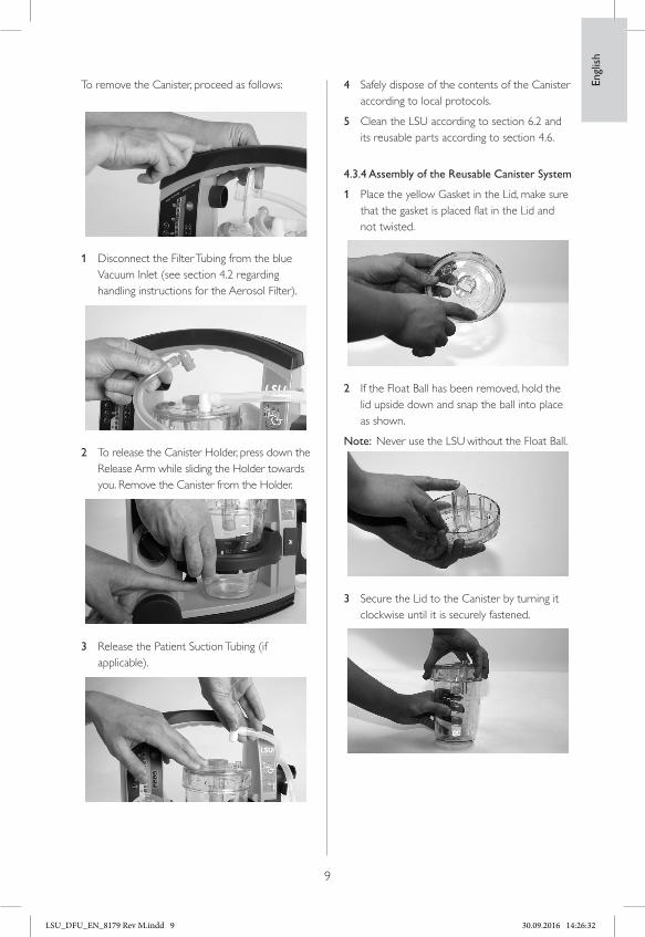
To remove the Canister, proceed as follows:
1 Disconnect the Filter Tubing from the blue Vacuum Inlet (see section 4.2 regarding handling instructions for the Aerosol Filter).
2 To release the Canister Holder, press down the Release Arm while sliding the Holder towards you. Remove the Canister from the Holder.
3 Release the Patient Suction Tubing (if applicable).
4 Safely dispose of the contents of the Canister according to local protocols.
5 Clean the LSU according to section 6.2 and its reusable parts according to section 4.6.
4.3.4 Assembly of the Reusable Canister System
1 Place the yellow Gasket in the Lid, make sure that the gasket is placed flat in the Lid and not twisted.
2 If the Float Ball has been removed, hold the lid upside down and snap the ball into place as shown.
Note: Never use the LSU without the Float Ball.
3 Secure the Lid to the Canister by turning it clockwise until it is securely fastened.
LSU_DFU_EN_8179 Rev M.indd 9 30.09.2016 14:26:32

Engl
ish
10
4 Connect the Suction Catheter Adapter to the Patient Tube.
5 Connect the Angled Connector to the Patient Tube.
6 Mount the yellow Vacuum Seal in the centre hole of the Lid and push it into place.
7 Connect the Aerosol Filter (blue ring) to the blue Vacuum Inlet on the LSU. (Color code: Blue on Blue)
8 Insert the Canister in the canister holder and slide it into the LSU.
9 Connect the yellow Angled Connector to the yellow Vacuum Seal
10 Connect the Angled Connector on the Patient tubing to the PATIENT Inlet on the canister Lid.
11 Perform the Device Test according to section 7.
12 Wind the Patient Tubing on the Patient Tubing Holder.
13 Place the LSU on charge (see section 6.4)
LSU_DFU_EN_8179 Rev M.indd 10 30.09.2016 14:26:34

Engl
ish
11
Note: Connect tubing according to color code: Blue on Blue & Yellow on Yellow.
4.4 Reusable Canister System
Quick reference
The assembly of the tubing is illustrated on the right side of the LSU. 1 Connect the blue Aerosol filter
to the blue Vacuum Inlet.
2 Connect the yellow angled connector to the yellow Vacuum Seal.
3 Connect the Patient Tubing to the Patient inlet.
4.5 After Use
• When suction is complete, set Operating Knob to ”0” and inspect all parts for damage or excessive wear. Replace parts if necessary.
• Clean the LSU and its reusable parts according to section 6.2
• Perform the Device Test according to section 7.
• Place the LSU on charge (see section 6.4).
4.6 Decontamination of Laerdal Reusable Canister
4.6.1 Parts to be Decontaminated
After Each Use: 1 Canister Lid
2 Float Ball
3 Gasket.
4 Vacuum Seal
5 Angled Connectors
6 Canister
7 Patient Suction Tubing
8 Suction Catheter Adapter.
1.
4.3. 8.
5.
7.
6.
2.
4.6.2 Preparation
• Remove and empty the Canister according to section 4.3.
• Disassemble the Canister into separate parts as indicated in the picture above.
• The Float Ball on the reusable canister can be snapped out of the lid.
4.6.3 Rinsing
• Rinse all parts under cold running water.
• Immerse in warm water (30-40°C).
4.6.4 Cleaning
• Immerse all parts in hot water (60-70°C) containing a mild detergent (see section 6.3).
• Thoroughly clean all surfaces, use a brush where possible.
• Rinse in warm water and allow to dry.
• Inspect all parts to be visibly clean and dry.
Note: Thorough rinsing and cleaning are very important steps prior to disinfection.
LSU_DFU_EN_8179 Rev M.indd 11 30.09.2016 14:26:35

5. Serres Suction Bag system5.1 Overview
Vacuum Inlet
User Interface
Canister
Canister Holder
Release Arm
PATIENT Inlet
Suction Tube
Serres Vacuum Connector
Serres Suction Bag with filter
Holder for Suction Tubing
Battery Door
Engl
ish
12
5.2 Parts
Disposable Parts
• Suction bag with filter
• Serres Suction Tube
Suction Bag with FilterSerres Suction Tube
Reusable Parts
Parts to be cleaned or replaced regulary:• Canister
• Serres Vacuum Connector
Serres VacuumConnector
Canister
The Serres Suction Bag system contains a hydrophilic filter that shuts off the vacuum if the canister is full or the LSU tips over.
To restore the vacuum, replace the Suction bag:The disposable parts must be replaced after each use.
LSU_DFU_EN_8179 Rev M.indd 12 30.09.2016 14:26:37

Engl
ish
13
The reusable canister must be cleaned if needed according to manufacturer’s instructions for use.
Clean the Serres Vacuum Connector by wiping with a damp cloth or a sponge. Do not autoclave or attempt to disassemble.
5.3 Use
Note: Read all the cautions and warnings listed in section 1 thoroughly before you use the LSU.
5.3.1 Check list
• Check that no parts are missing and that all parts are clean.
• If you decide to operate the LSU from external power, connect to either external AC or DC power as described in section 3.4. If you decide to operate the LSU from internal battery, check that the battery is installed and charged.
• Check that the Serres Vacuum Connector is properly connected to the LSU and to the canister
Check that the lid of the canister is properly sealed:
1 Block patient inlet and turn on the LSU.
2 Vacuum will build up when all parts are assembled correctly.
5.3.2 Using the LSU
Note: The LSU should be operated and transported in the upright position to prevent overflow of suctioned material.
1 Unwrap the Serres Suction Tube.
2 Connect the Serres Suction Tube to the Patient inlet on the canister lid.
3 Attach appropriate suction catheter if necessary. Not supplied by Laerdal Medical.
4 Set the Operating Knob to the required vacuum level and the LSU will automatically be switched on and start to operate. The green power ON Indicator is lit continuously while the LSU is switched on.
5 When suctioning is complete, set the Operating Knob to “0”.
5.3.3 Empty the canister
Note: It is recommended to replace the SuctionBag when it is ¾ full.
When liquid reaches approximately 1000 ml, the LSU will not suction any more liquid. If overflow of liquid from the bag into the pump is suspected, the LSU must be returned to service (see section 8).
Overflow of suctioned material can damage the LSU.
Disconnect Serres Suction tube. Safely dispose of the Serres suction tube according to local protocols.
LSU_DFU_EN_8179 Rev M.indd 13 30.09.2016 14:26:38

Engl
ish
14
1 Plug Patient Inlet with plug provided on the lid. Disconnect the Serres Vacuum Connector from the canister.
2 Press the release arm while sliding the holder towards you to loosen or completely remove canister.
3 Remove suction bag from canister
4 Safely dispose of the Serres Suction bag according to local protocols.
5 Clean the LSU if needed according to section 6.2.
6 Clean the Serres canister if needed according manufacturers instructions for use.
Note: Clean the Serres Vacuum Connector by wiping with a damp cloth or a sponge.Do not autoclave or attempt to disassemble. The Serres Vacuum Connector should be replaced regularly.
5.3.4 Assembly of the Serres Suction Bag system
1 Place the canister in a canister holder in an upright position.
2 Partially insert the canister holder into the LSU.
3 Unfold the Suction Bag and place inside the canister. Suction bag has to be installed into equal size canister
4 Insert the Serres Vacuum Connector into the LSU Vacuum Inlet.
LSU_DFU_EN_8179 Rev M.indd 14 30.09.2016 14:26:40

Engl
ish
15
5 Fully insert canister holder into the LSU.
6 Insert the opposite side of the Serres Vacuum Connector into the canister.
7 Turn the operating knob to 500+ mmHg.
8 Close the Patient inlet with your finger and simultaneously push the middle of the lid down. The lid is properly installed when vacuum has reached 500 mmHg.
9 Release the patient inlet and make sure that the bag is fully inflated.
10 Perform the Device Test according to section 7.
11 Fasten the Suction Tubing on the Suction Tubing Holder
12 Place the LSU on charge (see section 6.4)
5.4 Serres Suction Bag System Quick Reference
Correct assembly of the tubing is illustrated on the right side of the LSU.
5.5 After Use
1 Inspect all parts of the LSU for damage and excessive wear. Replace parts if necessary. The Serres Vacuum Connector should be replaced regularly.
2 Place an unopened Serres Suction Tube on the side of the LSU.
3 Perform Device Test according to section 7.
4 Place the LSU on charge see section 6.4.
LSU_DFU_EN_8179 Rev M.indd 15 30.09.2016 14:26:42

6.3 Disinfection of reusable parts
To disinfect the parts, the following methods are recommended:
Method Temperature / Concentration Contact Time Post-treatment
Glutaraldehyde Room temperature / Conc.: 2% 60 minutes Rinse all parts warm water. Allow to dry.
Sodium Hypochlorite (not cleared for use in the US)
Room temperature / Conc.: 0.5% 20 minutes Rinse all parts warm water. Allow to dry.
Virkon Room temperature / Conc.: 1% 10 minutes Rinse all parts warm water. Allow to dry.
Steam autoclaving Autoclave at max. 121° C 60 minutes Allow parts to cool.
Engl
ish
16
6. Maintenance6.1 General
• Make sure the maintenance instructions under “After Use” are followed.
• If the device is not in frequent use (i.e. less than once a month), the Device Test (see section 7) should be performed both on a monthly basis and after each use.
6.2 Clean the Cabinet and parts
Warning: Disconnect the LSU from external power prior to cleaning.
Use a minimum of liquid to prevent any electrical shock hazard. Do not immerse the LSU or allow it to stand in water or other liquids. This can damage the device, and cause electrical shock resulting in injury to persons.
• Use a cloth or sponge that is dampened with a mild detergent (hand dishwashing liquid or similar) to clean the external surfaces of the LSU. Use a detergent that is compatible with the materials listed under section 11.7, and follow the detergent manufacturer´s instructions.
• Use a cloth or sponge dampened with water and wipe the surfaces again.
• Dry the surfaces using a clean cloth or a paper towel.
6.4 Charge the Battery
The internal rechargeable battery can be charged directly from external AC or DC power as described in section 3.4. No external charger is needed. To charge the battery, proceed as follows:
1 Make sure the Operating Knob is set to “0”. Connect either external AC or DC power to the LSU and charging will start automatically.
2 During charging the Battery Status Indicator will indicate approx. achieved battery capacity (see section 3.2.5 for details).
3 The LSU should be placed on charge for a minimum of 24 hours to reach full battery capacity. The fast charging gives approx. 80% capacity after 3 hours (for a new battery). Repetitive charging for only 3 hours is not recommended.
LSU_DFU_EN_8179 Rev M.indd 16 30.09.2016 14:26:42

Engl
ish
17
Note: • To maintain satisfactory operation of the
battery, it is recommended to place the LSU on continuous charge immediately after use and when not in use.
• It is recommended to always fully charge the battery. Repetitive charging to a lower capacity level will reduce battery life.
• If it is not possible to place the LSU on continuous charge when not in use, make sure the battery is charged for a minimum of 24 hours at least once a month.
• Do not store the battery when it is discharged. Always fully charge the battery before storage.
• Do not store the LSU with a discharged battery.
• The recommended ambient temperature for charging is from 15°C to 25°C.
• The battery will not be charged when the LSU is in operation.
• If no battery is installed, the battery status indicator will be fully lit for approx. 5 sec. until it is turned off.
• Replace the battery when it does not pass the Battery Quality Check (see section 6.6 for details) or after 3 years, whichever comes first.
• A completely discharged battery cannot be charged by the LSU and must be replaced.
• We recommend charging a spare battery every 6 months when stored in room temperature at 25°C (77°F ).
6.5 External Battery Charger
The LSU battery can also be charged in an optional External Battery Charger. See section 10.
6.6 Check the Battery Quality
If poor battery quality is suspected, charge the battery for a minimum of 24 hours and then perform the following test without connection to external power:
LED 4
LED 3
LED 2
LED 1
• Run the Device Test and then let the LSU operate continuously at 500+ mmHg setting and free air flow for 20 minutes.
• If the LSU stops before completing the 20 minutes, the battery should be discarded.
6.7 Replace the Battery
Note: Use only batteries recommended by Laerdal Medical.
1 Open the Battery Door.
2 To remove the battery, push and move it slightly to the left and then release.
3 Withdraw the battery from the LSU.*
4 To insert a battery, push it fully in and then to the right to lock it.
5 Close the Battery Door.
6 After inserting the battery, place the LSU on charge unless a fully charged battery is inserted.
*When you discard the battery, dispose of safely in accordance with local protocols for sealed lead acid or Nickel Metal Hydride (NiMH) batteries.
LSU_DFU_EN_8179 Rev M.indd 17 30.09.2016 14:26:43

Engl
ish
18
6.8 Fastening brackets
The fastening bracket is used to hold the LSU in the optional wall bracket. Inspect the fastening brackets for wear and tear regularly. Replace if worn. See section 10.
Fastening brackets
6.9 Release arm for Canister holder
An extra release arm for the canister holder can be attached. See section 10.
7 Device testThe Device test is a user initiated test program for all models which can identify whether the LSU operates satisfactorily or if the LSU needs service.
The program runs 4 different tests:1 It tests for occlusions in the Suction System
(including canister and tubing).
2 It tests the vacuum build-up efficacy of the Pump System (How much vacuum is built up within 3 seconds).
3 It tests the maximum achievable vacuum level of the LSU (reaches this level within 10 seconds).
4 It tests if there are air leakages in the Pump System (including canister and tubing).
7.1 Setup
Before the test can be performed make sure that: • The Patient Suction Tubing is unwound and
not blocked or bent.
• The Suction Catheter Adapter is removed from its holder (if applicable).
• The Canister Lid, Vacuum Connector, Angled Connector with Patient Tubing are securely fastened.
LSU_DFU_EN_8179 Rev M.indd 18 30.09.2016 14:26:44

Engl
ish
19
7.2 Run the Test
Note: If you need to interrupt the test and revert to normal operation, turn the Operating Knob to another position and then select the required setting.
1 Press and hold the TEST-Button while setting the Operating Knob to 500+ mmHg.
Note: Do not release the TEST-Button until min. 2 seconds after the Operating Knob has been set to 500+ mmHg. The test will start immediately
2 As soon as LED 2 from the bottom of the Battery Status Indicator comes on (takes approx. one second), fully block the Patient Suction Tubing.*
3 Keep the tubing blocked while LED 2 , 3 and 4 lights up.
4 Release the tubing when LED 1 comes on again.
5 Evaluate the test results (See section 7.3)
6 After evaluating the test results turn the Operating Knob to “0” to exit the Device Test.
Note: To indicate that the LSU is in test mode, the Power ON Indicator will flash rapidly (approx. twice per second) until you exit the test program.* If the tubing is not occluded within 2 minutes, the test will be interrupted and the Power ON Indicator will start to flash slowly (approx. once per second). To restart the test, set the Operating Knop to “0” and start over again.
LSU_DFU_EN_8179 Rev M.indd 19 30.09.2016 14:26:45

7.3 Evaluation of Device Test Results
After the test is completed, the Vacuum Indicator will automatically display the first result (blockage). To display the other results press the TEST-Button once for each test. If you continue pressing the button after the 4th test result has been displayed, the earlier results will be repeated (Test 1,2,3,4,1,etc.). To exit the test program, set the Operating Knob to another position.
Test No.The program has tested for
Battery indicator
Test result indication Action if test failed
Test 1 Blockage in the Suction System (including canister and tubing)
LED #1 lit up Test Passed <100 mmHg
FAIL100 mmHgPASS
Check possible blockages (e.g. twisted tubing, blocked filter, blocked filter in the liner) and run the Device.Test again. If the High Efiiciency Filtration Kit is installed the pass limit is 150mmHg
Test 2 The vacuum build-up efficacy of the Pump System (How much vacuum is built up within 3 seconds)
LED #2 lit up Test Passed >300 mmHg
PASS300 mmHgFAIL
Check Connectors, Tubes and Canister Lid for leakage* or damage.Check exhaust outlet for occlusion and run the Device Test again
Test 3 The maximum achievable vacuum level of the LSU (reaches this level within 10 seconds)
LED #3 lit up Test Passed >500 mmHg
PASS500 mmHgFAIL
Check Connectors, Tubes and Canister Lid for leakage* or damage. Check exhaust outlet for occlusion and run the Device Test again
Test 4 Air leakages in the Pump System (including canister and tubing)
LED #4 lit up Test Passed >450 mmHg
PASS450 mmHgFAIL
Check Connectors, Tubes and Canister Lid for leakage* or damage and run the Device Test again
* If it is not obvious where the system is leaking; go step by step through the connections. Start by disconnecting the Vacuum Tube at the Canister and run the Device Test (blocking the tube). Reconnect the tube and disconnecting the patient tube, run device test (block the PATIENT inlet on the Canister). Continue with other connections until the leakage is identified.Note: If the LSU does not pass one or more of the steps in this test after suggested actions are taken, the device might need to be returned for service (see the Troubleshooting guide).
Engl
ish
20
LSU_DFU_EN_8179 Rev M.indd 20 30.09.2016 14:26:46

8. ServicingThere are no user serviceable parts inside the cabinet. Do not open cabinet. Please note that wear and tear parts of the pump mechanism should be changed every third year.Refer servicing to personnel qualified by Laerdal Medical, or to Laerdal Medical or one of its authorised distributors.
9. Trouble Shooting
Fault Condition Action
The LSU does not operate with the AC or DC Power Cord connected.
External Power Indicator isnot lit when the OperatingKnob is set to “0”.
Check power cord connections and the external AC or DC power source.
External Power Indicator is lit. The LSU must be returned for service (see section 8).
The LSU cannot be operated from the internal battery.
Power ON Indicator is OFF.ORAll the lights in the front panel flash on and off repeatedly.
Check that battery is installed.
Place the LSU on charge.
If still faulty after charging completed,remove and replace the battery (see section 6.7).
The LSU operates, but little or no suction available.
Vacuum Seal blocked by float ball.
Unplug the Vacuum Seal to release the vacuum
Canister full. Remove and replace the Canister (see section 4.3, 5.3)
Poor vacuum connection between Pump Unit and Canister.
Install the Vacuum ConnectorTubing correctly.
Patient Suction Tubing twistedor blocked.
Replace the filter or liner if the filter is blocked Untwist the Patient SuctionTubing and/or clear blockageor replace the tubing.
(Serres) Lid is not properly sealed
Seal lid using vacuum, not force. See section 5.3.4
Battery Status Indicator is not ON.
Battery is not charged. Check power cord connections and that battery is installed
Vacuum Indicator indicates more than 100 mmHg with free air flow
Tube(s) is kinked or twisted Straighten / untwist the tube(s).
The LSU does not charge with the AC or DC power cord connected
The external Power indicatoris not lit.
Check power cord connectionsand the external AC- or DC-power source.The LSU must be returned for service (see section 8).A flat battery cannot be recharged
Engl
ish
21
LSU_DFU_EN_8179 Rev M.indd 21 30.09.2016 14:26:46

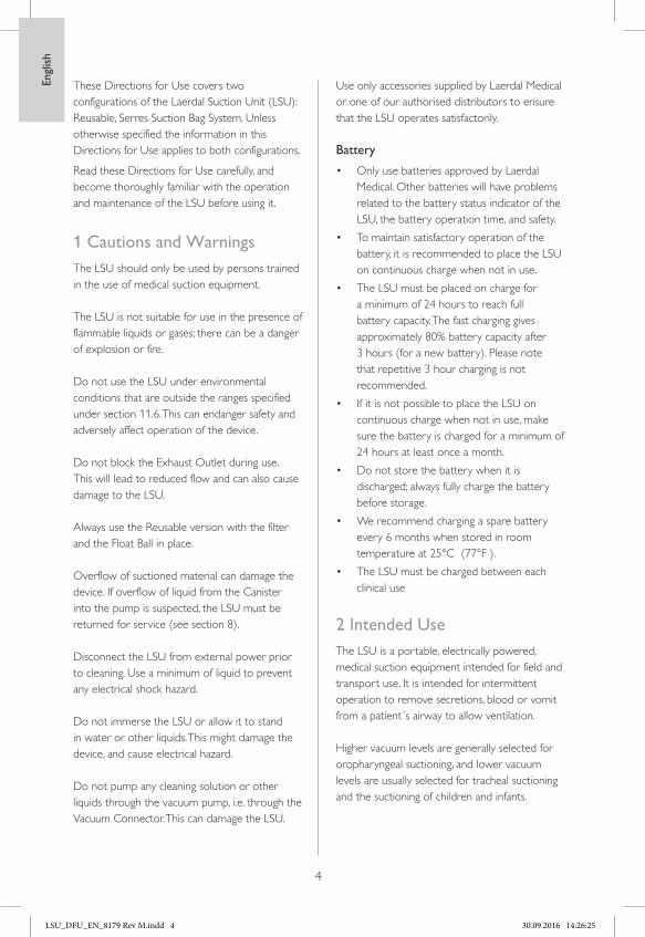
10. Accessories and PartsCat. No. Description
78 00 00 LSU w/Reusable Canister78 00 30 LSU w/ Serres Suction Bag System(Label on back side of cabinet: REF 78 00 xx)
Reusable
78 12 00 Aerosol Filter for LSU Reusable Canister77 04 10 Suction Tubing 150 cm w/o tip65 01 13 Suction Catheter adapter, pkg. 1078 40 00 LSU Reusable Canister78 10 06 Angled Connectors, pkg. 1078 10 02 Float Ball, pkg. 1078 40 07 Vacuum Seal78 40 08 Gasket78 04 30 LSU Reusable Canister Holder
Serres
57 151 Serres Suction Bag (1000 ml, Blue)58 33 181 Serres Suction Tube (non-sterile CH25) 180 cm78 12 06 Serres Vacuum Connector78 04 12 Disposable patient tubing 180cm57 300 Serres Canister (1000ml, Transparent)78 04 51 Serres Canister Holder
Serres pre 2014
78 12 04 Serres Vacuum Connector Tubing78 12 03 Serres High Efficiency Filtration Kit78 04 50 Serres Canister Holder
Engl
ish
22
78 12 00
78 10 06
78 10 02
78 40 07 78 04 3078 40 08
65 01 13
77 04 10
78 40 00
58 33 181
78 04 12
57 151
78 12 06
78 12 04 78 12 03
78 04 50
78 04 51
Serres pre 2014
57 300
LSU_DFU_EN_8179 Rev M.indd 22 30.09.2016 14:26:46

23
All versions
78 04 33 Strap for Tubing78 04 32 Release Arm78 02 00 DC-Power Cord78 02 10 AC-Power Cord US78 02 20 AC-Power Cord EU78 02 30 AC-Power Cord UK78 08 00 LSU Battery - NiMH 78 04 00 LSU Battery - Lead Acid78 04 36 Fasten bracket left/right78 04 35 Holder for water bottle79 35 00 Water Container
Accessories (all versions)
78 20 00 Carrying Bag (full covering)78 26 00 Wall Bracket w/DC-Power Cord78 26 10 Wall Bracket w/AC-Power Cord US78 26 20 Wall Bracket w/AC-Power Cord EU78 26 30 Wall Bracket w/AC-Power Cord UK78 26 40 Wall Bracket wo/ Power Cord78 23 00 Shoulder Strap78 24 00 Side Pouch78 04 40 External Charger kit
79 35 00
78 04 32
78 02 10 78 02 00
78 02 20
78 02 30
78 04 3678 04 0078 08 00
78 23 00
78 26 1078 26 20
78 26 3078 26 40
78 20 00
78 04 40
78 24 00
78 04 35
78 04 33
Engl
ish
LSU_DFU_EN_8179 Rev M.indd 23 30.09.2016 14:26:47

Engl
ish
24
11. Specifications11.1 Classification
Electrically powered medical suction equipment for field and transport use, according toISO10079-1High vacuum/high flow.Not suitable for use in the presence of flammable liquids or gases.Internally powered/class ll equipment type BF, according to IEC 60601-1The degree of protection provided by the chassis is according to IP34D:• Protected against solid foreign objects of
2,5 mm Ø and greater
• Protected against splashing water
• Protected against access with a wire
11.2 General tolerance
Overall tolerance ±5%
11.3 Physical Characteristics
Size: 315 mm (12,4 in) x 330 mm (13 in) x 160 mm (6,3 in), (h x w x d)Weight: 4kg (8,9 lbs) (including battery NiMH)Canister Capacity: 1000 mlCanister graduationaccuracy: ±5% of full scalePatient Suction Tubing (non-sterile) Cat.No 770410: 8 mm (0.315 in.) inside diameter x 1.5 m (59 in.) length
11.4 Operation
Approx. free air flow at different settings:
mmHg 80 120 200 350 500+
l/min 12 16 20 23 >25
Approx. battery operation time (free air flow) at different settings (±10%):
mmHg 80 120 200 350 500+
min 3h20 2h20 1h30 1h 45
Approx noise levels (free air flow) at different settings:
mmHg 80 120 200 350 500+
dBA 48 48 51 53 56
Vacuum - Max.: > 500 mmHg (67 kPa).Vacuum - Range: 80 - 500+ mmHg (11 - 67 kPa).Vacuum Indicator accuracy: ±5% of full scale.
11.4.1 Operation with High Efficiency Filtration Kit
The flow and operation time of the LSU will be reduced when the Vacuum Connector Tubing is replaced with a High Efficiency Filtration Kit.
The LSU with High Efficiency Filtration Kit installed is in accordance with ISO 10079-1.
The filter has an efficiency of 99.97% down to a particle size of 0.3 μm.
11.5 Power Requirements
Operating/charging AC:** 100-240 VAC +10%/-15%, 50-60 Hz +/- 3 Hz (100-240 VAC),Operating/charging DC:** 12-28 VDC +/-10%.Battery: 12 VDC 2 Ah, NiMH, rechargeable, 12 VDC 2 Ah, Sealed Lead - Acid, rechargeable Charging Time: 3 hours for approx. 80% battery capacity, 24 hours for fully charged.Fuses: The LSU has no fuses to be replaced by the user (see section 9).
** The external AC power source must be able to deliver a current of min. 1A and the externalDC power source min. 6A, if not the LSU may switch to battery operation.
LSU_DFU_EN_8179 Rev M.indd 24 30.09.2016 14:26:47

Engl
ish
25
11.6 Environmental Conditions
Operating/Charging Temperature: 0° C (32°F) to + 40° C (104° F).
Recommended Charging Temperature: 15°C (59°F) to + 25°C (77°F ).
Long term Storage Temperature: 0° C (32°F) to + 40° C (104° F).
Max. 24 hour Storage Temperature: -30° C (-22°F) to + 70° C (158° F).
Humidity (Operating & Storage): 5 - 95% RH non-condensing
11.7 Material Chart
• Cabinet front: Poly Cabonate/Acrylonitrile Butadiene Styrene (PC/ABS)
• Protector for front: Styrene Ethylene Betyl Styrene (SEBS)
• Cabinet back: PC/ABS
• Cabinet base w/Protector: PC/ABS + SEBS
• Battery door: SEBS
• Connector retainer for battery:
• Poly Oxy Methylene (POM)
• Operating Knob: POM
• Rotor for Operating Knob: PC/ABS
• Manifold for vacuum: POM
• Canister Holder: PP
• Handle w/Protector: PC/ABS + SEBS
• Manifold for exhaust: POM
• Strap for patient suction tubing: SEBS
• Canister Holder Release Arm: POM
• User Interface: Polyester
• Vacuum Connector: Silicone
• Suction Catheter Adapter: PC
• Suction Catheter Adapter Holder: PC
• LSU Reusable Canister : PC - HT
• Lid w/Floater Valve Cylinder,
• Gasket for Lid, LSU Reusable Canister : Silicone
• Full covering Carrying Bag: PVC coated Polyester
• Side Pouch: PVC coated Polyester
• Shoulder Strap: POM + Polyester
• Wallbracket: Aluminium + Steel + PA with fibers Aerosol Filter, LSU Reusable Canister : PVC + ABS Styrene-Butadiene Copolymer (SBC)
• Float Ball, LSU Reusable Canister : PP
• Vacuum Plug, LSU Reusable Canister : Silicone
• Serres Canister : PC
• The angle connector of the canister : TPE
• Serres Canister Holder: PP
• Serres Suction Bag: PE + PP
• Serres Vacuum Connection PC + PBT
11.7.1 Dismantling/Disposal
When discarding the LSU, we recommend it be dismantled and discarded according to local protocol. Dismantle the LSU by unscrewing the screws on the back side of the LSU, remove the components and sort according to the table in 11.7.
The cleaned LSU can also be delivered to your local Laerdal Medical representative for dismantling/disposal. Laerdal Medical AS will not charge any fee for the dismantling; Sender is reponsible for the cost of the shipment.
LSU_DFU_EN_8179 Rev M.indd 25 30.09.2016 14:26:47

Engl
ish
26
11.8 Symbols
(Direct Current).
3
3N
N
!
(Alternating Current).
Class II Equipment, according to IEC 60601-1
Type BF applied part, according to IEC 60601-1
IP34D The degree of protection provided by the chassis according to IP34D
This product is in compliance with the essential requirements of MDD 93/42/EEC as amended by Council Directive 2007/47/EC and Council Directive 2011/65/EU relating to restriction on the use of certain Hazardous Substance (RoHS 2)
Warning: Parts of this product are designed for single patient use only. Do not re-use. Re-use will lead to increased risk of cross contamination, degradation of performance and/or device malfunction. Laerdal Medical is not responsible for any consequences of re-use
Date of production.
See Directions for Use.
Unique product type identification
This appliance is marked according to the European directive 2012/19/EC on Waste Electrical and Electronic Equipment (WEEE). The symbol on the product, or on the documents accompanying the product, indicates that this appliance may not be treated as household waste. Instead it shall be handed over to the applicable collection point for the recycling of elec-trical and electronic equipment.
This product complies with the following ANSI/UL and CSA standards
CSA Standards: CAN/CSA-C22.2 No:0-M91 General Requirements – Canadian Electrical Code, part II
CAN/CSA-C22.2 No:601.1-M90 Medical Electrical Equipment Part I: General Requirements for Safety
CAN/CSA-C22.2 No:601.1S1-94 Supplement No 1-94 to CAN/CSA-C22.2 No. 601.1-M90 – Medical Electrical Equipment – Part 1: General Requirements for Safety US Standards:
UL Standard No:2601.1 Medical Electrical Equipment
11.9 EMC Specifications
MEDICAL ELECTRICAL EQUIPMENT needs special precautions regarding EMC and needs to be installed and put into service according to the EMC provided in this section. Portable and mobile RF communication equipment can affect MEDICAL ELECTRICAL EQUIPMENT.
Warning:
MEDICAL ELECTRICAL EQUIPMENT should not be used adjacent to or stacked with other equipment. If adjacent or stacked use is necessary, the MEDICAL ELECTRICAL EQUIPMENT should be observed to verify normal operation in the configuration in which it will be used.
Maximum cable length, AC Power cord: 1.5 metersMaximum cable length, DC Power cord: 1.5 meters
Warning:
The use of accessories, transducers and cables other than those specified, with exception of transducers and cables sold by Laerdal Medical as replacement parts for internal components, may result in increased emission or decreased immunity of the LSU.
0434
3
3N
N
!
LSU_DFU_EN_8179 Rev M.indd 26 30.09.2016 14:26:47

Engl
ish
27
Guidance and manufacturer’s declaration – electromagnetic immunity
The Laerdal Suction Unit (LSU) is intended for use in the electromagnetic environment specified below. The customer or the user of the LSU should assure that it is used in such an environment.
Immunity test IEC 60601-1-2 test level Compliance level Electromagnetic environment - guidance
Electrostatic discharge(ESD)IEC 61000-4-2
±6 kV contact±8 kV air
±6 kV contact±8 kV air
Floors should be wood, concrete or ceramictile. If floors are covered with synthetic material,the relative humidity should be at least 30%.
Electrical fasttransient/burst.IEC 61000-4-4
±2 kV for powersupply lines
±2 kV for powersupply lines
Mains power quality should be that of a typical commercial or hospital environment.
Surge IEC 61000-4-5 ± 1 kV differential mode± 2kV common mode
± 1 kV differential mode± 2kV common mode
Mains power quality should be that of a typical commercial or hospital environment.
Voltage dips, shortinterruptions and voltage variations on power supply input lines.IEC 61000-4-11
< 5% UT(> 95% dip in UT) for 0,5 cycle40% UT (60% dip in UT) for 5 cycles70% UT (30% dip in UT)for 25 cycles< 5% UT(> 95% dip in UT)for 5 sec.
< 5% UT(> 95% dip in UT) for 0,5 cycle40% UT (60% dip in UT) for 5 cycles70% UT (30% dip in UT)for 25 cycles< 5% UT(> 95% dip in UT)for 5 sec.
Mains power quality should be that of a typicalcommercial or hospital environment.
Power Frequency (50Hz/60Hz) magnetic field. IEC 61000-4-8
3A/m 3A/m
NOTE: UT is the AC mains voltage prior to application of the test level.
Guidance and manufacturer’s declaration – electromagnetic immunity
The Laerdal Suction Unit (LSU) is intended for use in the electromagnetic environment specified below. The customer or the user of the LSU should assure that it is used in such an environment.
Immunity test IEC 60601-1-2 test level Electromagnetic environment - guidance
RF emissionsCISPR 11
Group 1 The LSU uses RF energy only for its internal function. Therefore, its RF emissions are very low and are not likely to cause any interference in nearby electronic equipment.
RF emissionsCISPR 11
Class B The LSU is suitable for use in all establishments, including domestic establishments and those directly connected to the public low-voltage power supply network that supplies buildings used for domestic purposes.
Harmonic emissionsIEC 61000-3-2
Class A
Voltage fluctuations/flicker emissionsIEC 61000-3-3
Complies
LSU_DFU_EN_8179 Rev M.indd 27 30.09.2016 14:26:47

Guidance and manufacturer’s declaration – electromagnetic immunity
The Laerdal Suction Unit (LSU) is intended for use in the electromagnetic environment specified below. The customer or the user of the LSU should assure that it is used in such an environment.
Immunity test IEC 60601-1-2 test level Compliance level Electromagnetic environment - guidance
Conducted RFIEC/EN 61000-4-6
Radiated RFIEC/EN 61000-4-3
3 Vrms150 kHz to 80MHz
3 V/m80 MHz to 2,5GHz
3 Vrms
10 V/m
Portable and mobile RF communications equipment should be used no closer to any part of the LSU, including cables, than the recommended separation distance calculated from the equation applicable to frequency of the transmitter.Recommended separation distanced=1.2 •Pd=0.35•P 80 MHz to 800 MHzd=0.7•P 800 MHz to 2,5 GHzwhere P is the maximum output power rating of the transmitter in watts (W) according to the transmitter manufacturer and d is the recommended separation distance in meters (m).Field strengths from fixed RF transmitters, as determined by an electromagnetic site surveya, should be less than the compliance level in each frequency rangeb.Interference may occur in the vicinity of equipment marked with the following symbol:
NOTE 1. At 80 MHz and 800 MHz, the higher frequency range applies.NOTE 2. These guidelines may not apply in all situations. Electromagnetic propagation is affected by absorption and reflection from structures, objects and people.
a. Field strengths from fixed transmitters, such as base stations for radio (cellular/cordless) telephones and land mobile radios, amateur radio, AM and FM radio broadcast and TV broadcast cannot be predicted theoretically with accuracy.To assess the electromagnetic environment due to fixed RF transmitters, an electromagnetic site survey should be considered. If the measured field strength in the location in which the LSU is used exceeds the applicable RF compliance level above, the LSU should be observed to verify normal operation. If abnormal performance is observed, additional measures may be necessary, such as reorienting or relocating the LSU.b. Over the frequency range 150 kHz to 80 MHz, field strength should be less than 3 V/m.
Engl
ish
28
12 Limited WarrantyThe LSU comes with a five (5) year limitedwarranty*. See the enclosed “Laerdal GlobalWarranty” for terms and conditions.The warranty is also available at www.laerdal.com
* Excluding the canister, tubing systems andbattery
13 AddressesManufacturer:
Laerdal Medical ASTanke Svilandsgate 30P.O.Box 3774002 StavangerNorway
Distribution:
For World Wide distribution,see Global Warranty orwww.laerdal.com
LSU_DFU_EN_8179 Rev M.indd 28 30.09.2016 14:26:48

LSU_DFU_EN_8179 Rev M.indd 29 30.09.2016 14:26:48

LSU_DFU_EN_8179 Rev M.indd 30 30.09.2016 14:26:48

LSU_DFU_EN_8179 Rev M.indd 31 30.09.2016 14:26:48

8179
Rev
M© 2016 Laerdal Medical AS. All rights reserved. Manufacturer : Laerdal Medical ASP.O. Box 377, Tanke Svilandsgt. 30, 4002 Stavanger, Norway T: (+47) 51 51 17 00
www.laerdal.com
LSU_DFU_EN_8179 Rev M.indd 32 30.09.2016 14:26:48