Embed Size (px)
Citation preview
www.mwignitions.com
TM
LSU4 UEGO OPERATORS MANUAL
TM

www.mwignitions.com
TM
CONTENTS
Introduction ...........................................................page 1
Uego Sensor ...........................................................page3
Installation...............................................................page4
Operation ................................................................page5
Software ..................................................................page6
M&W LCD ...............................................................page9
Kit Components ......................................................page10
Graphs ...................................................................page12
Specifications ........................................................page17
Wiring Diagrams ...................................................page18
Copyright NoticeM&W Ignitions is the owner of Copyright in this publication, including layouts, drawings, text and partnumbering systems. This publication must not be reproduced in whole or in part without written authori-sation from M&W Ignitions.
Publication Release 1.0
M&W Ignitions6 Horning StreetKurnell 2231SydneyAustralia
Ph +61 2 96688348Fax +61 2 96688209
email: [email protected]
www.mwignitions.com
TM
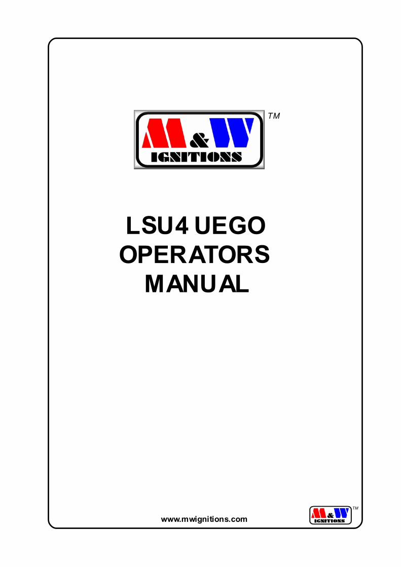
The M&W Uego system uses a Universal Exhaust Gas Oxygen sensor and this workscompletely differently from a normal oxygen sensor you would find in your car. It allowsprecise measurement over a wide AFR range.
UEGO sensor systems are used by all original equipment manufacturers for ECUmapping and are also widely used in motorsports including F1.
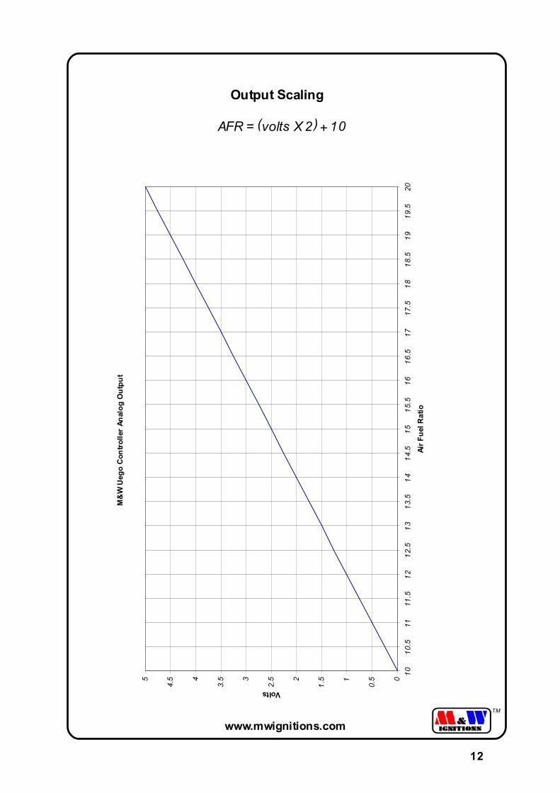
The microprocessor controlled M&W Uego controller features a fully linerized real time0 to 5 volt analog output giving 10 to 20/1 air fuel ratio.This simple scaling allows easy input into data acquisition systems and engine manage-ment systems. 12V operation with a cigarette lighter plug allows easy fitment for vehicletesting.
The RS232 port allows connection to IBM compatible computers and laptops with DOS,Windows 95/98/NT/2000/XP and PocketPC software available. The controller uses a truewide range Bosch LSU4 sensor which when used with the tail pipe probe adapter pro-vides a very versatile tuning tool for engine mapping and diagnostic purposes.
INTRODUCTION
1
www.mwignitions.com
TM
INTRODUCTION
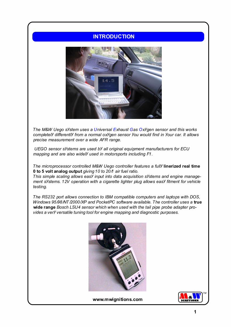
0-5V RS232
ecu
DAQsystem
DOSWIN95/98/NT/XP
Output configurations
0-5V analog output and RS232 provide common interface options.
PocketPCMeter
M&W
M&W LCD
2
www.mwignitions.com
TM
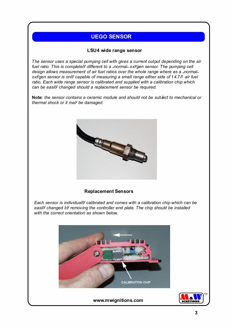
LSU4 wide range sensor
The sensor uses a special pumping cell with gives a current output depending on the airfuel ratio. This is completely different to a �normal� oxygen sensor. The pumping celldesign allows measurement of air fuel ratios over the whole range where as a �normal�oxygen sensor is only capable of measuring a small range either side of 14.7/1 air fuelratio. Each wide range sensor is calibrated and supplied with a calibration chip whichcan be easily changed should a replacement sensor be required.
Note: the sensor contains a ceramic module and should not be subject to mechanical orthermal shock or it may be damaged.
UEGO SENSOR
Replacement Sensors
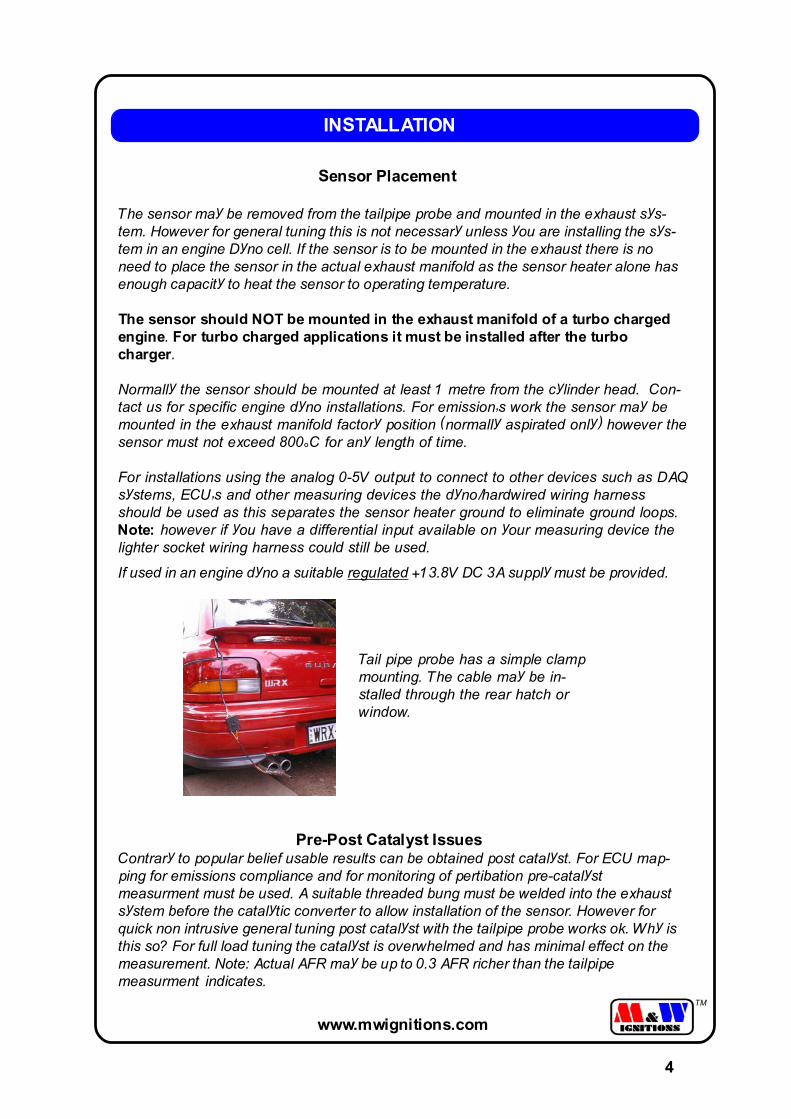
Each sensor is individually calibrated and comes with a calibration chip which can beeasily changed by removing the controller end plate. The chip should be installedwith the correct orientation as shown below.
3
www.mwignitions.com
TM
INSTALLATION
Sensor Placement
The sensor may be removed from the tailpipe probe and mounted in the exhaust sys-tem. However for general tuning this is not necessary unless you are installing the sys-tem in an engine Dyno cell. If the sensor is to be mounted in the exhaust there is noneed to place the sensor in the actual exhaust manifold as the sensor heater alone hasenough capacity to heat the sensor to operating temperature.
The sensor should NOT be mounted in the exhaust manifold of a turbo chargedengine. For turbo charged applications it must be installed after the turbocharger.
Normally the sensor should be mounted at least 1 metre from the cylinder head. Con-tact us for specific engine dyno installations. For emission�s work the sensor may bemounted in the exhaust manifold factory position (normally aspirated only) however thesensor must not exceed 800°C for any length of time.
For installations using the analog 0-5V output to connect to other devices such as DAQsystems, ECU�s and other measuring devices the dyno/hardwired wiring harnessshould be used as this separates the sensor heater ground to eliminate ground loops.Note: however if you have a differential input available on your measuring device thelighter socket wiring harness could still be used.
If used in an engine dyno a suitable regulated +13.8V DC 3A supply must be provided.
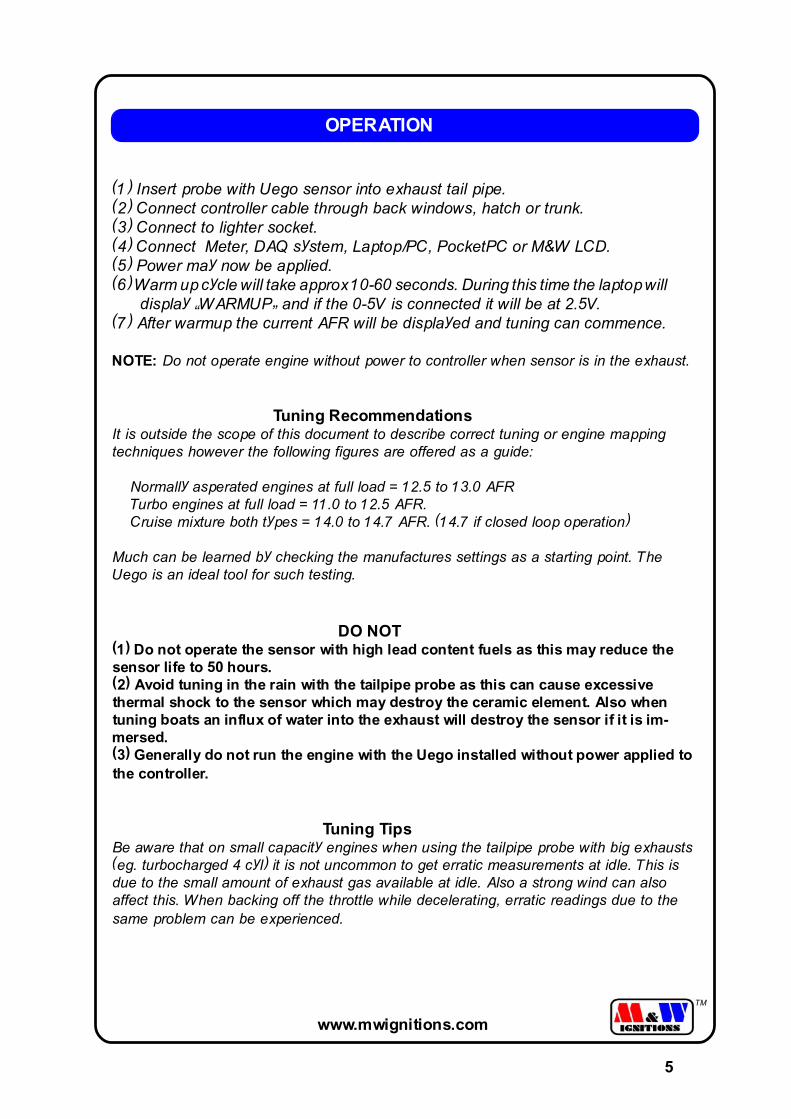
Tail pipe probe has a simple clampmounting. The cable may be in-stalled through the rear hatch orwindow.
4
Pre-Post Catalyst IssuesContrary to popular belief usable results can be obtained post catalyst. For ECU map-ping for emissions compliance and for monitoring of pertibation pre-catalystmeasurment must be used. A suitable threaded bung must be welded into the exhaustsystem before the catalytic converter to allow installation of the sensor. However forquick non intrusive general tuning post catalyst with the tailpipe probe works ok. Why isthis so? For full load tuning the catalyst is overwhelmed and has minimal effect on themeasurement. Note: Actual AFR may be up to 0.3 AFR richer than the tailpipemeasurment indicates.
www.mwignitions.com
TM
(1) Insert probe with Uego sensor into exhaust tail pipe.(2) Connect controller cable through back windows, hatch or trunk.(3) Connect to lighter socket.(4) Connect Meter, DAQ system, Laptop/PC, PocketPC or M&W LCD.(5) Power may now be applied.(6) Warm up cycle will take approx 10-60 seconds. During this time the laptop will display �WARMUP� and if the 0-5V is connected it will be at 2.5V.(7) After warmup the current AFR will be displayed and tuning can commence.
NOTE: Do not operate engine without power to controller when sensor is in the exhaust.
Tuning RecommendationsIt is outside the scope of this document to describe correct tuning or engine mappingtechniques however the following figures are offered as a guide:
Normally asperated engines at full load = 12.5 to 13.0 AFR Turbo engines at full load = 11.0 to 12.5 AFR. Cruise mixture both types = 14.0 to 14.7 AFR. (14.7 if closed loop operation)
Much can be learned by checking the manufactures settings as a starting point. TheUego is an ideal tool for such testing.
DO NOT(1) Do not operate the sensor with high lead content fuels as this may reduce thesensor life to 50 hours.(2) Avoid tuning in the rain with the tailpipe probe as this can cause excessivethermal shock to the sensor which may destroy the ceramic element. Also whentuning boats an influx of water into the exhaust will destroy the sensor if it is im-mersed.(3) Generally do not run the engine with the Uego installed without power applied tothe controller.
Tuning TipsBe aware that on small capacity engines when using the tailpipe probe with big exhausts(eg. turbocharged 4 cyl) it is not uncommon to get erratic measurements at idle. This isdue to the small amount of exhaust gas available at idle. Also a strong wind can alsoaffect this. When backing off the throttle while decelerating, erratic readings due to thesame problem can be experienced.
OPERATION
5
www.mwignitions.com
TM
DOS
System Requirements (Min)286 20MhzVGA1 X Serial port (Com1 only)
InstallationThe EXE file can be run from the floppy or copied to the hard disk. Thisprogram is configured for COM1 port only.
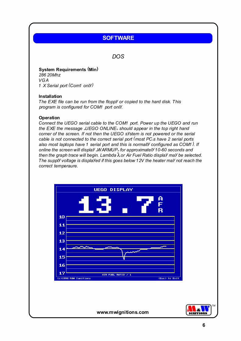
OperationConnect the UEGO serial cable to the COM1 port. Power up the UEGO and runthe EXE the message �UEGO ONLINE� should appear in the top right handcorner of the screen. If not then the UEGO system is not powered or the serialcable is not connected to the correct serial port (most PC�s have 2 serial portsalso most laptops have 1 serial port and this is normally configured as COM1). Ifonline the screen will display �WARMUP� for approximately 10-60 seconds andthen the graph trace will begin. Lambda or Air Fuel Ratio display may be selected.The supply voltage is displayed if this goes below 12V the heater may not reach thecorrect temperaure.
SOFTWARE
6
www.mwignitions.com
TM
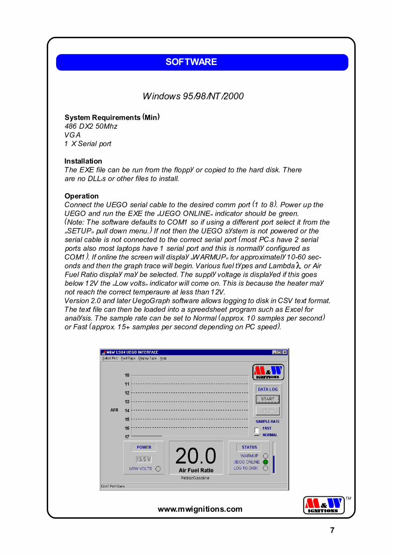
Windows 95/98/NT/2000
System Requirements (Min)486 DX2 50MhzVGA1 X Serial port
InstallationThe EXE file can be run from the floppy or copied to the hard disk. Thereare no DLL�s or other files to install.
OperationConnect the UEGO serial cable to the desired comm port (1 to 8). Power up theUEGO and run the EXE the �UEGO ONLINE� indicator should be green.(Note: The software defaults to COM1 so if using a different port select it from the�SETUP� pull down menu.) If not then the UEGO system is not powered or theserial cable is not connected to the correct serial port (most PC�s have 2 serialports also most laptops have 1 serial port and this is normally configured asCOM1). If online the screen will display �WARMUP� for approximately 10-60 sec-onds and then the graph trace will begin. Various fuel types and Lambda or AirFuel Ratio display may be selected. The supply voltage is displayed if this goesbelow 12V the �Low volts� indicator will come on. This is because the heater maynot reach the correct temperaure at less than 12V.Version 2.0 and later UegoGraph software allows logging to disk in CSV text format.The text file can then be loaded into a spreedsheet program such as Excel foranalysis. The sample rate can be set to Normal (approx. 10 samples per second)or Fast (approx. 15+ samples per second depending on PC speed).
SOFTWARE
7
www.mwignitions.com
TM
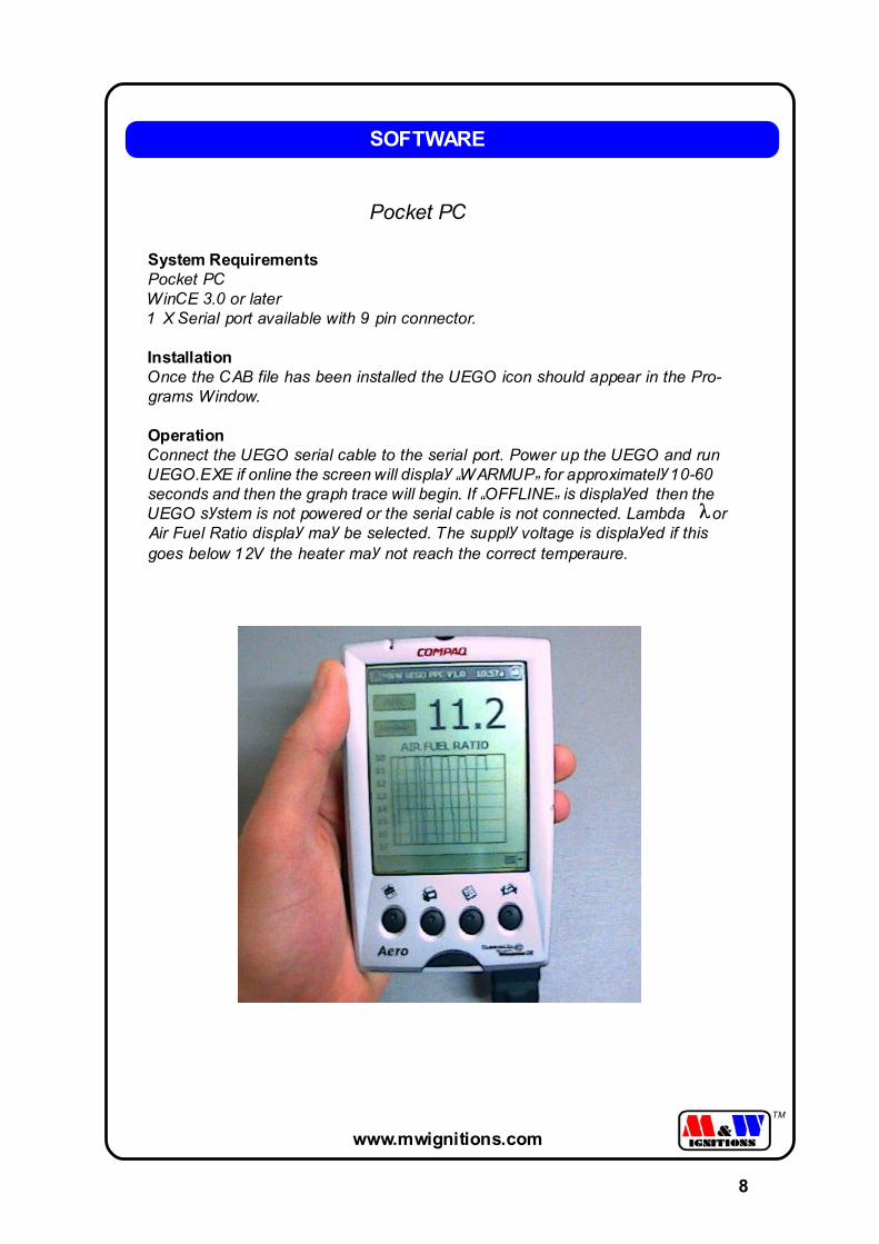
Pocket PC
System RequirementsPocket PCWinCE 3.0 or later1 X Serial port available with 9 pin connector.
InstallationOnce the CAB file has been installed the UEGO icon should appear in the Pro-grams Window.
OperationConnect the UEGO serial cable to the serial port. Power up the UEGO and runUEGO.EXE if online the screen will display �WARMUP� for approximately 10-60seconds and then the graph trace will begin. If �OFFLINE� is displayed then theUEGO system is not powered or the serial cable is not connected. Lambda orAir Fuel Ratio display may be selected. The supply voltage is displayed if thisgoes below 12V the heater may not reach the correct temperaure.
SOFTWARE
8
www.mwignitions.com
TM
M&W LCD
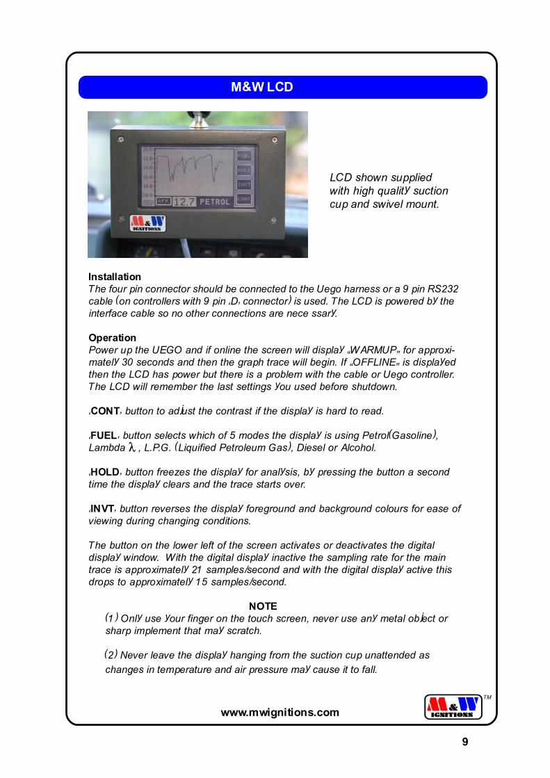
InstallationThe four pin connector should be connected to the Uego harness or a 9 pin RS232cable (on controllers with 9 pin �D� connector) is used. The LCD is powered by theinterface cable so no other connections are nece ssary.
OperationPower up the UEGO and if online the screen will display �WARMUP� for approxi-mately 30 seconds and then the graph trace will begin. If �OFFLINE� is displayedthen the LCD has power but there is a problem with the cable or Uego controller.The LCD will remember the last settings you used before shutdown.
�CONT� button to adjust the contrast if the display is hard to read.
�FUEL� button selects which of 5 modes the display is using Petrol(Gasoline),Lambda , L.P.G. (Liquified Petroleum Gas), Diesel or Alcohol.
�HOLD� button freezes the display for analysis, by pressing the button a secondtime the display clears and the trace starts over.
�INVT� button reverses the display foreground and background colours for ease ofviewing during changing conditions.
The button on the lower left of the screen activates or deactivates the digitaldisplay window. With the digital display inactive the sampling rate for the maintrace is approximately 21 samples/second and with the digital display active thisdrops to approximately 15 samples/second.
NOTE(1) Only use your finger on the touch screen, never use any metal object orsharp implement that may scratch.
(2) Never leave the display hanging from the suction cup unattended as
changes in temperature and air pressure may cause it to fall.
9
LCD shown suppliedwith high quality suctioncup and swivel mount.
www.mwignitions.com
TM
LSU4 UEGO SENSOR
UEGO CONTROLLER
MAIN WIRING HARNESS
STANDARD UEGO KIT COMPONENTS
TAIL PIPE PROBE
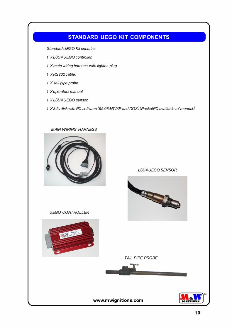
Standard UEGO Kit contains:
1 X LSU4 UEGO controller.
1 X main wiring harness with lighter plug.
1 X RS232 cable.
1 X tail pipe probe.
1 X operators manual.
1 X LSU4 UEGO sensor.
1 X 3.5" disk with PC software (95/98/NT/XP and DOS) (PocketPC available by request).
10
www.mwignitions.com
TM
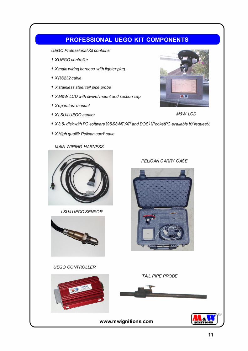
PROFESSIONAL UEGO KIT COMPONENTS
UEGO Professional Kit contains:
1 X UEGO controller
1 X main wiring harness with lighter plug.
1 X RS232 cable
1 X stainless steel tail pipe probe
1 X M&W LCD with swivel mount and suction cup
1 X operators manual
1 X LSU4 UEGO sensor
1 X 3.5" disk with PC software (95/98/NT/XP and DOS) (PocketPC available by request).
1 X High quality Pelican carry case
LSU4 UEGO SENSOR
UEGO CONTROLLER
MAIN WIRING HARNESS
TAIL PIPE PROBE
M&W LCD
PELICAN CARRY CASE
11
www.mwignitions.com
TM
M&
W U
ego
Co
ntr
oll
er A
nal
og
Ou
tpu
t
0
0.51
1.52
2.53
3.54
4.55
1010
.511
11.5
1212
.513
13.5
1414
.515
15.5
1616
.517
17.5
1818
.519
19.5
20
Air
Fu
el R
atio
Volts Output Scaling
AFR = (volts X 2) + 10
12
www.mwignitions.com
TM
La
mb
da
Ch
art
fo
r P
etr
ol (
Ga
solin
e)
9.5
10.0
10.5
11.0
11.5
12.0
12.5
13.0
13.5
14.0
14.5
15.0
15.5
16.0
16.5
17.0
17.5
18.0
18.5
19.0
19.5
20.0
20.5
0.70
0.75
0.80
0.85
0.90
0.95
1.00
1.05
1.10
1.15
1.20
1.25
1.30
1.35
Lam
bd
a
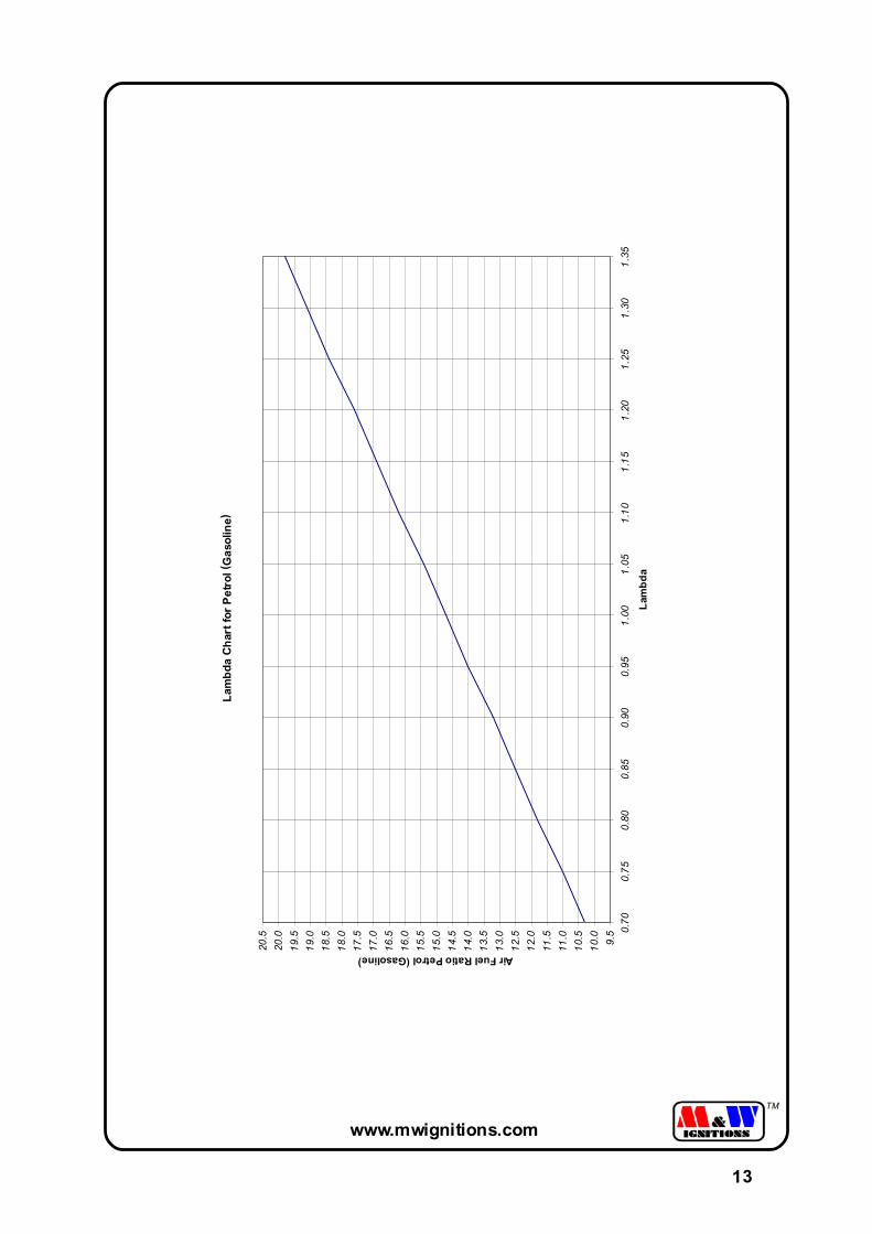
Air Fuel Ratio Petrol (Gasoline)
13
www.mwignitions.com
TM
Lam
bd
a C
har
t fo
r A
lco
ho
l
3.5
4.0
4.5
5.0
5.5
6.0
6.5
7.0
7.5
8.0
8.5
9.0
9.5 0.
700.
750.
800.
850.
900.
951.
001.
051.
101.
151.
201.
251.
301.
35
La
mb
da
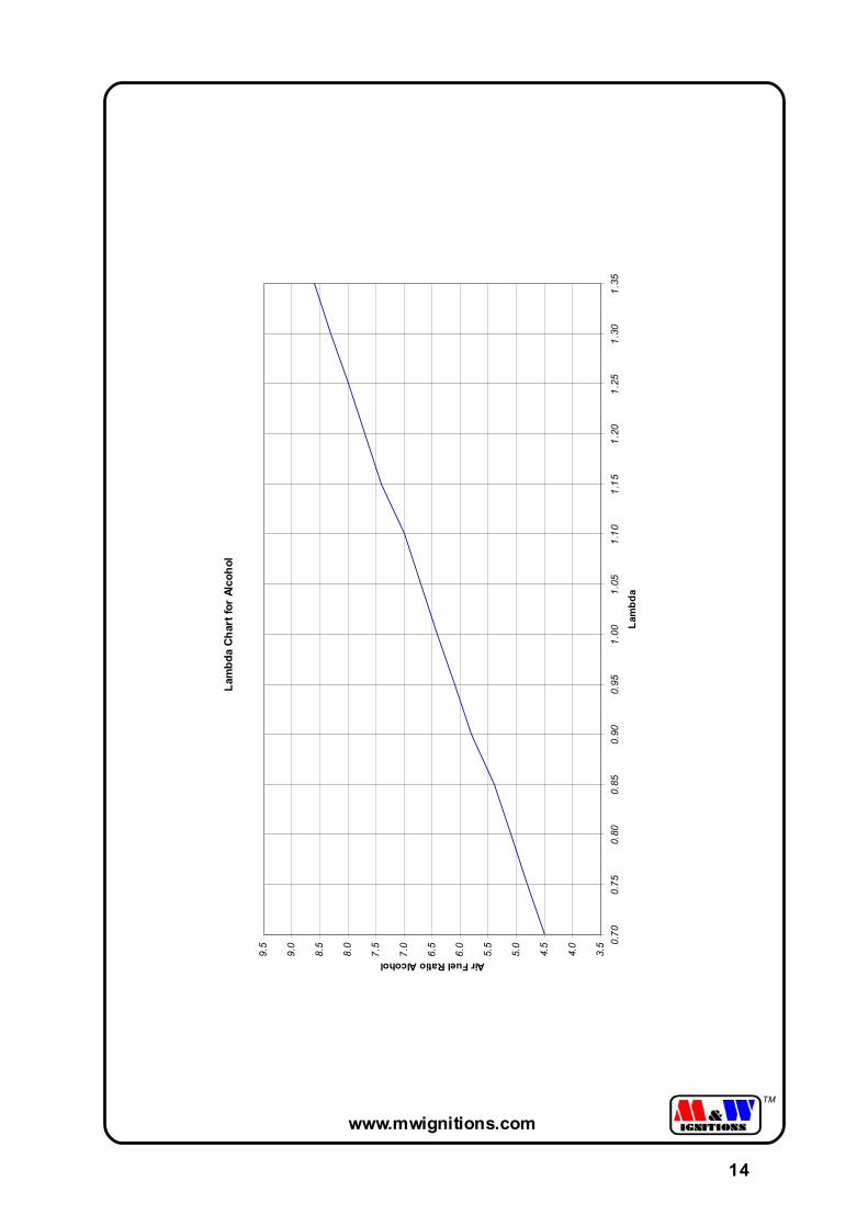
Air Fuel Ratio Alcohol
14
ww
w.m
wig
nitio
ns.co
m
TM
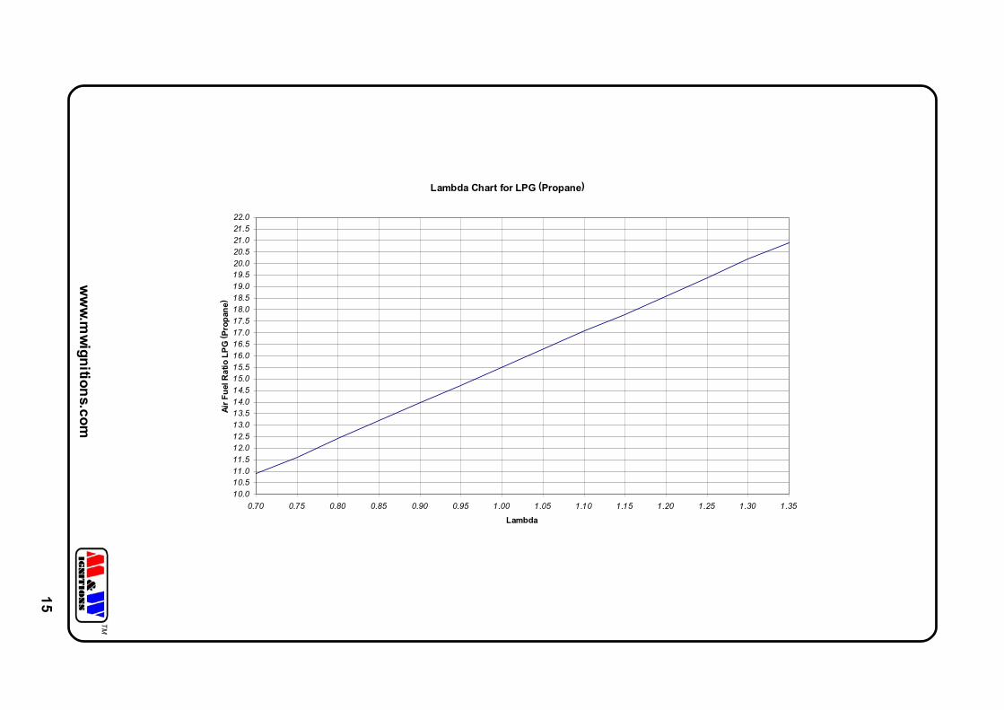
Lambda Chart for LPG (Propane)
10.0
10.511.0
11.5
12.012.5
13.0
13.514.0
14.5
15.015.5
16.0
16.517.0
17.5
18.018.5
19.0
19.520.0
20.5
21.021.5
22.0
0.70 0.75 0.80 0.85 0.90 0.95 1.00 1.05 1.10 1.15 1.20 1.25 1.30 1.35
Lambda
Air
Fu
el R
atio
LP
G (
Pro
pan
e)
15
www.mwignitions.com
TM
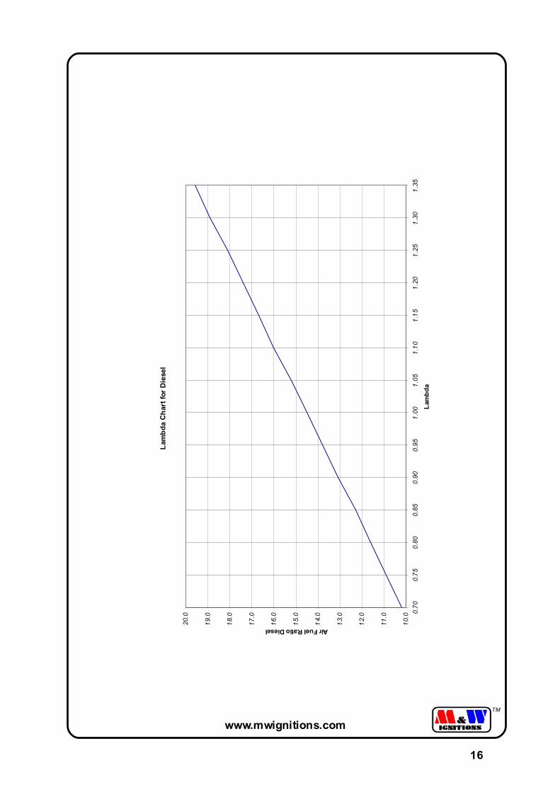
Lam
bd
a C
ha
rt f
or
Die
sel
10.0
11.0
12.0
13.0
14.0
15.0
16.0
17.0
18.0
19.0
20.0
0.70
0.75
0.80
0.85
0.90
0.95
1.00
1.05
1.10
1.15
1.20
1.25
1.30
1.35
Lam
bd
a
Air Fuel Ratio Diesel
16
www.mwignitions.com
TM
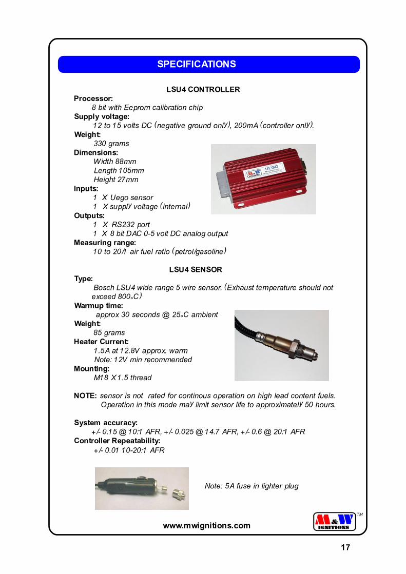
LSU4 CONTROLLERProcessor: 8 bit with Eeprom calibration chipSupply voltage:
12 to 15 volts DC (negative ground only), 200mA (controller only).Weight: 330 gramsDimensions: Width 88mm Length 105mm Height 27mmInputs:
1 X Uego sensor1 X supply voltage (internal)
Outputs:1 X RS232 port1 X 8 bit DAC 0-5 volt DC analog output
Measuring range:10 to 20/1 air fuel ratio (petrol/gasoline)
LSU4 SENSORType:
Bosch LSU4 wide range 5 wire sensor. (Exhaust temperature should not exceed 800°C)Warmup time:
approx 30 seconds @ 25°C ambientWeight: 85 gramsHeater Current: 1.5A at 12.8V approx. warm Note: 12V min recommendedMounting: M18 X 1.5 thread
NOTE: sensor is not rated for continous operation on high lead content fuels. Operation in this mode may limit sensor life to approximately 50 hours.
System accuracy: +/- 0.15 @ 10:1 AFR, +/- 0.025 @ 14.7 AFR, +/- 0.6 @ 20:1 AFRController Repeatability: +/- 0.01 10-20:1 AFR
SPECIFICATIONS
Note: 5A fuse in lighter plug
17
1 2 3 4
A
B
C
D
4321
D
C
B
A Title
Number RevisionSize
A4
Date: 17-Dec-2003 Sheet of File: C:\M&W\..\LSU4 UEGO Harness.sch Drawn By: M&W
1 1
1.1
LSU4 UEGO HARNESS
7
6
5
4
3
2
1
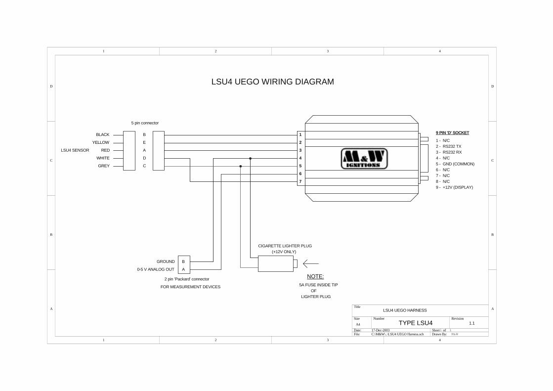
GROUND
5 pin connector
2 pin 'Packard' connector
B
E
A
D
C
0-5 V ANALOG OUT
CIGARETTE LIGHTER PLUG
NOTE:
FOR MEASUREMENT DEVICES
A
B
(+12V ONLY)
5A FUSE INSIDE TIPOF
LIGHTER PLUG
LSU4 SENSOR
TYPE LSU4
RED
BLACK
WHITE
YELLOW
GREY
9 PIN 'D' SOCKET
1 - N/C2 - RS232 TX3 - RS232 RX4 - N/C5 - GND (COMMON)6 - N/C7 - N/C8 - N/C9 - +12V (DISPLAY)
LSU4 UEGO WIRING DIAGRAM


![TEPANTITLA, EL ]UEGO DE PELOTA*](https://img.pdfslide.net/doc/110x75/589d7f801a28ab7c4a8ba7f8/tepantitla-el-uego-de-pelota.jpg)


![El ]uego: texto dramático y montaje](https://img.pdfslide.net/doc/110x75/62d60ffb3c1d70777f523000/el-uego-texto-dramtico-y-montaje.jpg)