Embed Size (px)
Citation preview
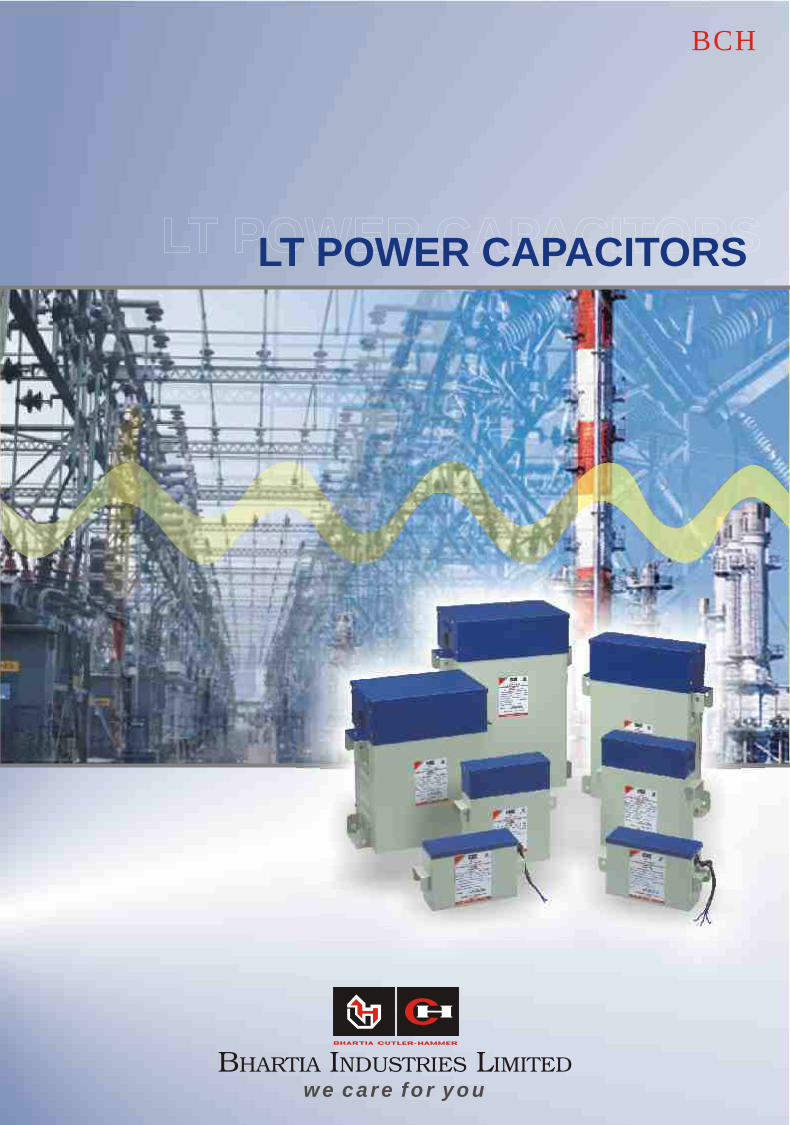
LT POWER CAPACITORSLT POWER CAPACITORS
we c a r e fo r y ou
LT POWER CAPACITORS
BCH
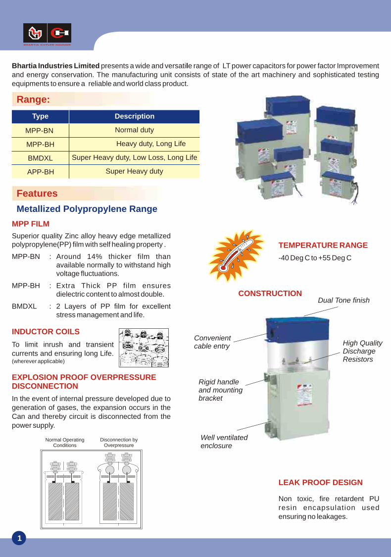
Bhartia Industries Limited presents a wide and versatile range of LT power capacitors for power factor Improvement and energy conservation. The manufacturing unit consists of state of the art machinery and sophisticated testing equipments to ensure a reliable and world class product.
Description
Normal duty
Type
MPP-BN
MPP-BH
BMDXL
APP-BH
Heavy duty, Long Life
Super Heavy duty, Low Loss, Long Life
Super Heavy duty
1
Superior quality Zinc alloy heavy edge metallized polypropylene(PP) film with self healing property .
MPP-BN : Around 14% thicker film thanavailable normally to withstand high voltage fluctuations.
MPP-BH : Extra Thick PP film ensures dielectric content to almost double.
BMDXL : 2 Layers of PP film for excellent stress management and life.
MPP FILM
To limit inrush and transient currents and ensuring long Life. (wherever applicable)
INDUCTOR COILS
TEMPERATURE RANGE
-40 Deg C to +55 Deg C
In the event of internal pressure developed due to generation of gases, the expansion occurs in the Can and thereby circuit is disconnected from the power supply.
EXPLOSION PROOF OVERPRESSURE DISCONNECTION
Non toxic, fire retardent PU resin encapsulation used ensuring no leakages.
LEAK PROOF DESIGN
Features
Normal Operating Conditions
Disconnection byOverpressure
Metallized Polypropylene Range
Range:
CONSTRUCTIONDual Tone finish
High QualityDischargeResistors
Well ventilatedenclosure
Rigid handleand mountingbracket
Convenientcable entry
2
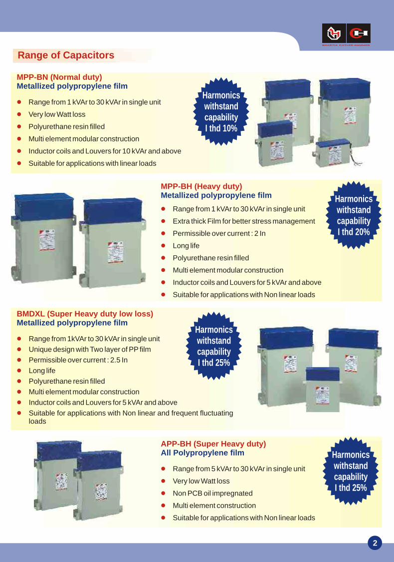
Range from 1 kVAr to 30 kVAr in single unit
Very low Watt loss
Polyurethane resin filled
Multi element modular construction
Inductor coils and Louvers for 10 kVAr and above
Suitable for applications with linear loads
MPP-BN (Normal duty) Metallized polypropylene film
Harmonics withstand capabilityI thd 10%
Range from 1 kVAr to 30 kVAr in single unit
Extra thick Film for better stress management
Permissible over current : 2 In
Long life
Polyurethane resin filled
Multi element modular construction
Inductor coils and Louvers for 5 kVAr and above
Suitable for applications with Non linear loads
MPP-BH (Heavy duty)Metallized polypropylene film Harmonics
withstand capabilityI thd 20%
Range from 5 kVAr to 30 kVAr in single unit
Very low Watt loss
Non PCB oil impregnated
Multi element construction
Suitable for applications with Non linear loads
APP-BH (Super Heavy duty)All Polypropylene film Harmonics
withstand capabilityI thd 25%
Range from 1kVAr to 30 kVAr in single unit
Unique design with Two layer of PP film
Permissible over current : 2.5 In
Long life
Polyurethane resin filled
Multi element modular construction
Inductor coils and Louvers for 5 kVAr and above
Suitable for applications with Non linear and frequent fluctuating loads
BMDXL (Super Heavy duty low loss)Metallized polypropylene film
Harmonics withstand capabilityI thd 25%
Range of Capacitors
3
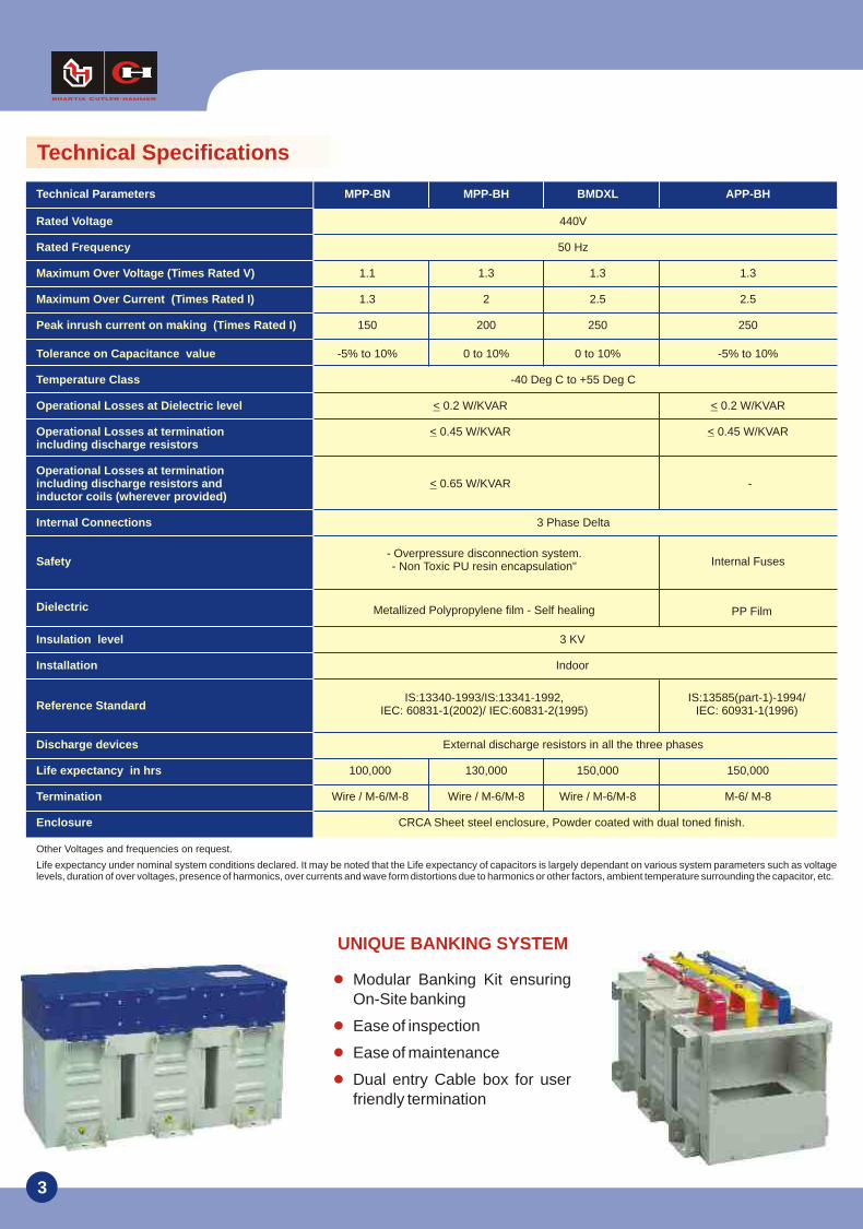
Metallized Polypropylene film - Self healing PP Film
IS:13585(part-1)-1994/IEC: 60931-1(1996)
Technical Specifications
- Overpressure disconnection system.- Non Toxic PU resin encapsulation"
IS:13340-1993/IS:13341-1992,IEC: 60831-1(2002)/ IEC:60831-2(1995)
Other Voltages and frequencies on request.
Life expectancy under nominal system conditions declared. It may be noted that the Life expectancy of capacitors is largely dependant on various system parameters such as voltage levels, duration of over voltages, presence of harmonics, over currents and wave form distortions due to harmonics or other factors, ambient temperature surrounding the capacitor, etc.
Technical Parameters MPP-BN MPP-BH BMDXL APP-BH
Rated Voltage
Rated Frequency
Maximum Over Voltage (Times Rated V)
Maximum Over Current (Times Rated I)
Peak inrush current on making (Times Rated I)
Tolerance on Capacitance value
Temperature Class
Operational Losses at Dielectric level
Operational Losses at terminationincluding discharge resistors
Operational Losses at terminationincluding discharge resistors andinductor coils (wherever provided)
Internal Connections
Safety
Dielectric
Insulation level
Installation
Reference Standard
Discharge devices
Life expectancy in hrs
Termination
Enclosure
440V
50 Hz
1.1 1.3 1.3 1.3
1.3 2 2.5 2.5
150 200 250 250
-5% to 10% 0 to 10% 0 to 10% -5% to 10%
-40 Deg C to +55 Deg C
< 0.2 W/KVAR < 0.2 W/KVAR
< 0.45 W/KVAR < 0.45 W/KVAR
< 0.65 W/KVAR -
3 Phase Delta
Internal Fuses
3 KV
Indoor
External discharge resistors in all the three phases
100,000 130,000 150,000 150,000
Wire / M-6/M-8 Wire / M-6/M-8 Wire / M-6/M-8 M-6/ M-8
CRCA Sheet steel enclosure, Powder coated with dual toned finish.
Modular Banking Kit ensuring On-Site banking
Ease of inspection
Ease of maintenance
Dual entry Cable box for user friendly termination
UNIQUE BANKING SYSTEM
4
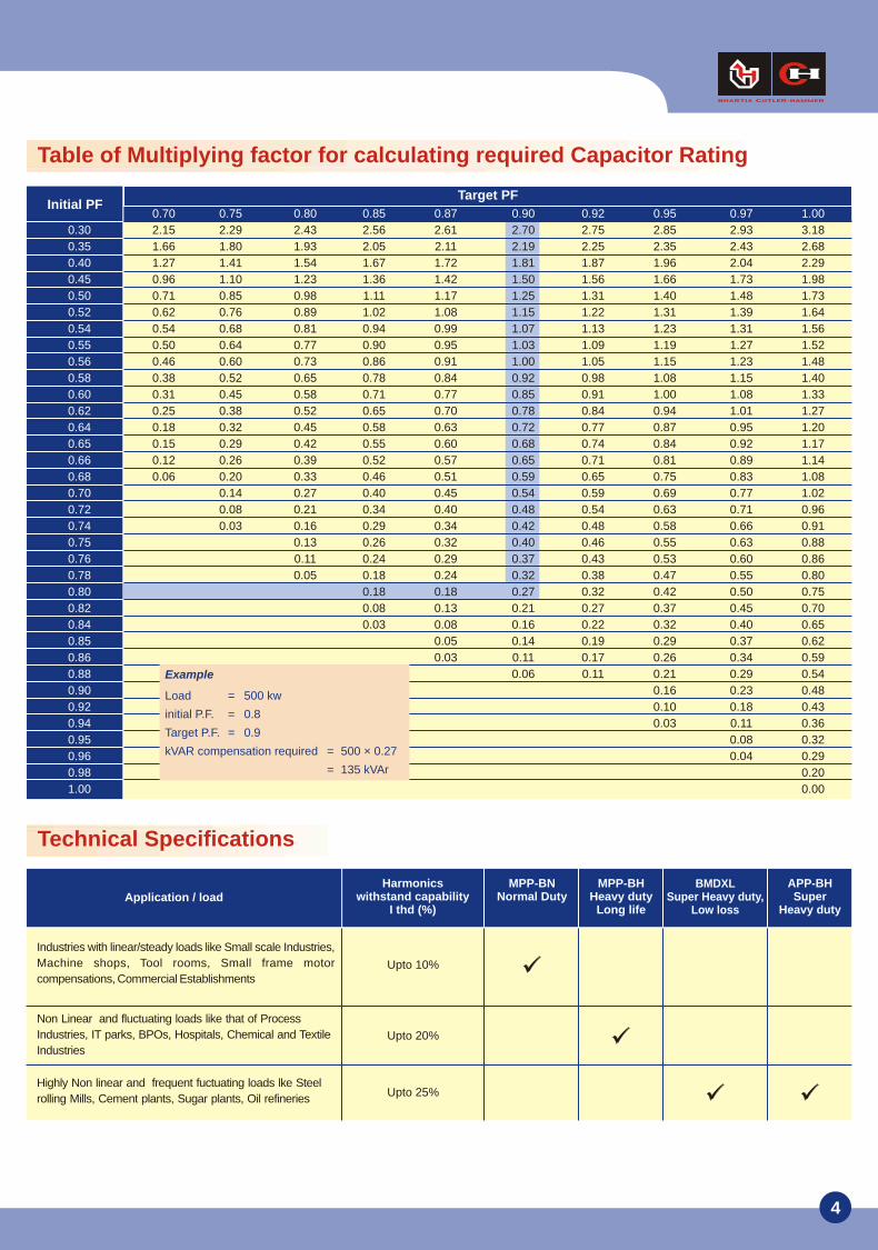
Target PF
Industries with linear/steady loads like Small scale Industries,
Machine shops, Tool rooms, Small frame motor
compensations, Commercial Establishments
Non Linear and fluctuating loads like that of Process
Industries, IT parks, BPOs, Hospitals, Chemical and Textile
Industries
Highly Non linear and frequent fuctuating loads lke Steel
rolling Mills, Cement plants, Sugar plants, Oil refineries
MPP-BN Normal Duty
MPP-BH Heavy duty
Long life
BMDXL Super Heavy duty,
Low loss
Harmonics withstand capability
I thd (%)
APP-BHSuper
Heavy dutyApplication / load
Table of Multiplying factor for calculating required Capacitor Rating
Upto 10%
Upto 20%
Upto 25%
Technical Specifications
Initial PF0.70 0.75 0.80 0.85 0.87 0.90 0.92 0.95 0.97 1.00
0.30
0.35
0.40
0.45
0.50
0.52
0.54
0.55
0.56
0.58
0.60
0.62
0.64
0.65
0.66
0.68
0.70
0.72
0.74
0.75
0.76
0.78
0.80
0.82
0.84
0.85
0.86
0.88
0.90
0.92
0.94
0.95
0.96
0.98
1.00
2.15 2.29 2.43 2.56 2.61 2.70 2.75 2.85 2.93 3.18
1.66 1.80 1.93 2.05 2.11 2.19 2.25 2.35 2.43 2.68
1.27 1.41 1.54 1.67 1.72 1.81 1.87 1.96 2.04 2.29
0.96 1.10 1.23 1.36 1.42 1.50 1.56 1.66 1.73 1.98
0.71 0.85 0.98 1.11 1.17 1.25 1.31 1.40 1.48 1.73
0.62 0.76 0.89 1.02 1.08 1.15 1.22 1.31 1.39 1.64
0.54 0.68 0.81 0.94 0.99 1.07 1.13 1.23 1.31 1.56
0.50 0.64 0.77 0.90 0.95 1.03 1.09 1.19 1.27 1.52
0.46 0.60 0.73 0.86 0.91 1.00 1.05 1.15 1.23 1.48
0.38 0.52 0.65 0.78 0.84 0.92 0.98 1.08 1.15 1.40
0.31 0.45 0.58 0.71 0.77 0.85 0.91 1.00 1.08 1.33
0.25 0.38 0.52 0.65 0.70 0.78 0.84 0.94 1.01 1.27
0.18 0.32 0.45 0.58 0.63 0.72 0.77 0.87 0.95 1.20
0.15 0.29 0.42 0.55 0.60 0.68 0.74 0.84 0.92 1.17
0.12 0.26 0.39 0.52 0.57 0.65 0.71 0.81 0.89 1.14
0.06 0.20 0.33 0.46 0.51 0.59 0.65 0.75 0.83 1.08
0.14 0.27 0.40 0.45 0.54 0.59 0.69 0.77 1.02
0.08 0.21 0.34 0.40 0.48 0.54 0.63 0.71 0.96
0.03 0.16 0.29 0.34 0.42 0.48 0.58 0.66 0.91
0.13 0.26 0.32 0.40 0.46 0.55 0.63 0.88
0.11 0.24 0.29 0.37 0.43 0.53 0.60 0.86
0.05 0.18 0.24 0.32 0.38 0.47 0.55 0.80
0.18 0.18 0.27 0.32 0.42 0.50 0.75
0.08 0.13 0.21 0.27 0.37 0.45 0.70
0.03 0.08 0.16 0.22 0.32 0.40 0.65
0.05 0.14 0.19 0.29 0.37 0.62
0.03 0.11 0.17 0.26 0.34 0.59
0.06 0.11 0.21 0.29 0.54
0.16 0.23 0.48
0.10 0.18 0.43
0.03 0.11 0.36
0.08 0.32
0.04 0.29
0.20
0.00
Example
Load = 500 kw
initial P.F. = 0.8
Target P.F. = 0.9
kVAR compensation required = 500 × 0.27
= 135 kVAr
5
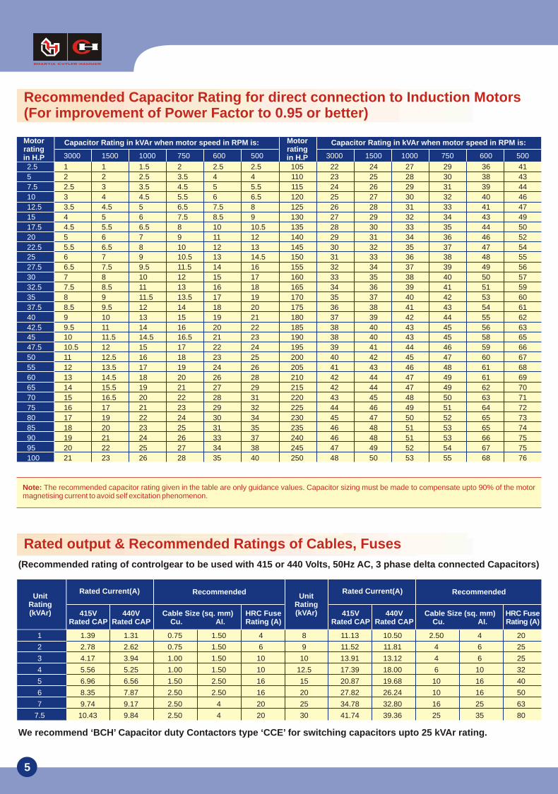
Recommended Capacitor Rating for direct connection to Induction Motors(For improvement of Power Factor to 0.95 or better)
Note: The recommended capacitor rating given in the table are only guidance values. Capacitor sizing must be made to compensate upto 90% of the motor magnetising current to avoid self excitation phenomenon.
Rated Current(A)
415VRated CAP
Unit Rating(kVAr) 440V
Rated CAPCable Size (sq. mm)
Cu. AI.HRC FuseRating (A)
Recommended Rated Current(A)
415VRated CAP
Unit Rating(kVAr) 440V
Rated CAPCable Size (sq. mm)
Cu. AI.HRC Fuse Rating (A)
Recommended
Rated output & Recommended Ratings of Cables, Fuses
(Recommended rating of controlgear to be used with 415 or 440 Volts, 50Hz AC, 3 phase delta connected Capacitors)
We recommend ‘BCH’ Capacitor duty Contactors type ‘CCE’ for switching capacitors upto 25 kVAr rating.
Motorratingin H.P
Capacitor Rating in kVAr when motor speed in RPM is: Capacitor Rating in kVAr when motor speed in RPM is:Motorratingin H.P
1 1 1.5 2 2.5 2.5 105 22 24 27 29 36 41
2 2 2.5 3.5 4 4 110 23 25 28 30 38 43
2.5 3 3.5 4.5 5 5.5 115 24 26 29 31 39 44
3 4 4.5 5.5 6 6.5 120 25 27 30 32 40 46
3.5 4.5 5 6.5 7.5 8 125 26 28 31 33 41 47
4 5 6 7.5 8.5 9 130 27 29 32 34 43 49
4.5 5.5 6.5 8 10 10.5 135 28 30 33 35 44 50
5 6 7 9 11 12 140 29 31 34 36 46 52
5.5 6.5 8 10 12 13 145 30 32 35 37 47 54
6 7 9 10.5 13 14.5 150 31 33 36 38 48 55
6.5 7.5 9.5 11.5 14 16 155 32 34 37 39 49 56
7 8 10 12 15 17 160 33 35 38 40 50 57
7.5 8.5 11 13 16 18 165 34 36 39 41 51 59
8 9 11.5 13.5 17 19 170 35 37 40 42 53 60
8.5 9.5 12 14 18 20 175 36 38 41 43 54 61
9 10 13 15 19 21 180 37 39 42 44 55 62
9.5 11 14 16 20 22 185 38 40 43 45 56 63
10 11.5 14.5 16.5 21 23 190 38 40 43 45 58 65
10.5 12 15 17 22 24 195 39 41 44 46 59 66
11 12.5 16 18 23 25 200 40 42 45 47 60 67
12 13.5 17 19 24 26 205 41 43 46 48 61 68
13 14.5 18 20 26 28 210 42 44 47 49 61 69
14 15.5 19 21 27 29 215 42 44 47 49 62 70
15 16.5 20 22 28 31 220 43 45 48 50 63 71
16 17 21 23 29 32 225 44 46 49 51 64 72
17 19 22 24 30 34 230 45 47 50 52 65 73
18 20 23 25 31 35 235 46 48 51 53 65 74
19 21 24 26 33 37 240 46 48 51 53 66 75
20 22 25 27 34 38 245 47 49 52 54 67 75
21 23 26 28 35 40 250 48 50 53 55 68 76
3000 1500 1000 750 600 500 3000 1500 1000 750 600 500
2.5
5
7.5
10
12.5
15
17.5
20
22.5
25
27.5
30
32.5
35
37.5
40
42.5
45
47.5
50
55
60
65
70
75
80
85
90
95
100
1.39 1.31 0.75 1.50 4 8 11.13 10.50 2.50 4 20
2.78 2.62 0.75 1.50 6 9 11.52 11.81 4 6 25
4.17 3.94 1.00 1.50 10 10 13.91 13.12 4 6 25
5.56 5.25 1.00 1.50 10 12.5 17.39 18.00 6 10 32
6.96 6.56 1.50 2.50 16 15 20.87 19.68 10 16 40
8.35 7.87 2.50 2.50 16 20 27.82 26.24 10 16 50
9.74 9.17 2.50 4 20 25 34.78 32.80 16 25 63
10.43 9.84 2.50 4 20 30 41.74 39.36 25 35 80
1
2
3
4
5
6
7
7.5
6
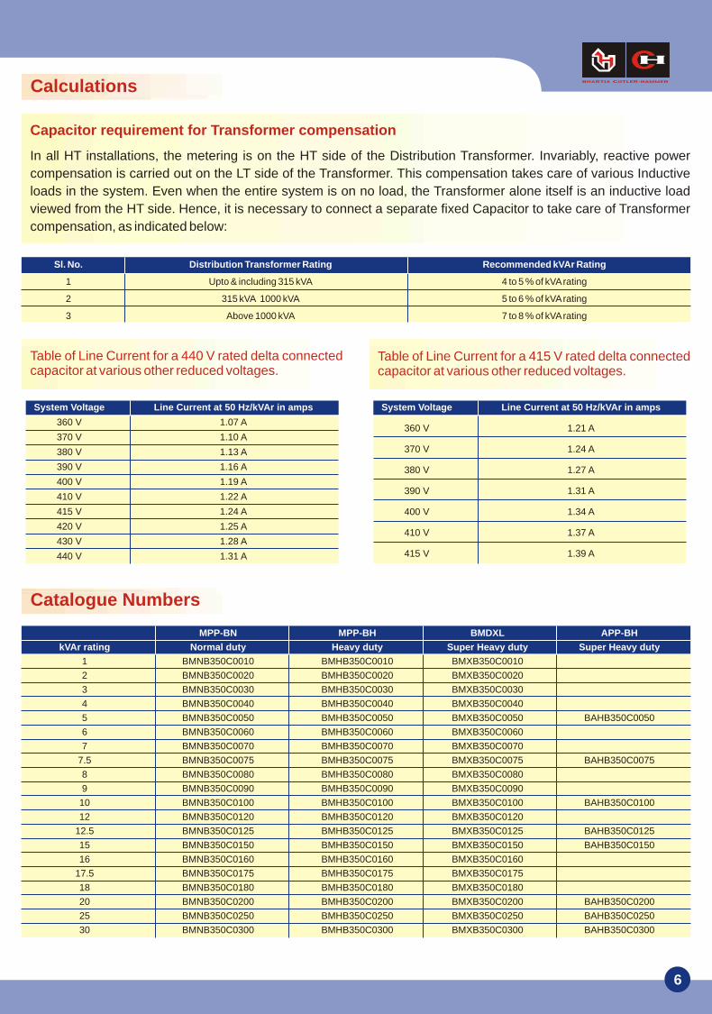
Catalogue Numbers
Capacitor requirement for Transformer compensation
In all HT installations, the metering is on the HT side of the Distribution Transformer. Invariably, reactive power
compensation is carried out on the LT side of the Transformer. This compensation takes care of various Inductive
loads in the system. Even when the entire system is on no load, the Transformer alone itself is an inductive load
viewed from the HT side. Hence, it is necessary to connect a separate fixed Capacitor to take care of Transformer
compensation, as indicated below:
Table of Line Current for a 440 V rated delta connected capacitor at various other reduced voltages.
Table of Line Current for a 415 V rated delta connected capacitor at various other reduced voltages.
Calculations
1 Upto & including 315 kVA 4 to 5 % of kVA rating
2 315 kVA 1000 kVA 5 to 6 % of kVA rating
3 Above 1000 kVA 7 to 8 % of kVA rating
Sl. No. Distribution Transformer Rating Recommended kVAr Rating
System Voltage Line Current at 50 Hz/kVAr in amps
360 V 1.07 A
370 V 1.10 A
380 V 1.13 A
390 V 1.16 A
400 V 1.19 A
410 V 1.22 A
415 V 1.24 A
420 V 1.25 A
430 V 1.28 A
440 V 1.31 A
360 V 1.21 A
370 V 1.24 A
380 V 1.27 A
390 V 1.31 A
400 V 1.34 A
410 V 1.37 A
415 V 1.39 A
System Voltage Line Current at 50 Hz/kVAr in amps
MPP-BN MPP-BH BMDXL APP-BH
kVAr rating Normal duty Heavy duty Super Heavy duty Super Heavy duty
1 BMNB350C0010 BMHB350C0010 BMXB350C0010
2 BMNB350C0020 BMHB350C0020 BMXB350C0020
3 BMNB350C0030 BMHB350C0030 BMXB350C0030
4 BMNB350C0040 BMHB350C0040 BMXB350C0040
5 BMNB350C0050 BMHB350C0050 BMXB350C0050 BAHB350C0050
6 BMNB350C0060 BMHB350C0060 BMXB350C0060
7 BMNB350C0070 BMHB350C0070 BMXB350C0070
7.5 BMNB350C0075 BMHB350C0075 BMXB350C0075 BAHB350C0075
8 BMNB350C0080 BMHB350C0080 BMXB350C0080
9 BMNB350C0090 BMHB350C0090 BMXB350C0090
10 BMNB350C0100 BMHB350C0100 BMXB350C0100 BAHB350C0100
12 BMNB350C0120 BMHB350C0120 BMXB350C0120
12.5 BMNB350C0125 BMHB350C0125 BMXB350C0125 BAHB350C0125
15 BMNB350C0150 BMHB350C0150 BMXB350C0150 BAHB350C0150
16 BMNB350C0160 BMHB350C0160 BMXB350C0160
17.5 BMNB350C0175 BMHB350C0175 BMXB350C0175
18 BMNB350C0180 BMHB350C0180 BMXB350C0180
20 BMNB350C0200 BMHB350C0200 BMXB350C0200 BAHB350C0200
25 BMNB350C0250 BMHB350C0250 BMXB350C0250 BAHB350C0250
30 BMNB350C0300 BMHB350C0300 BMXB350C0300 BAHB350C0300
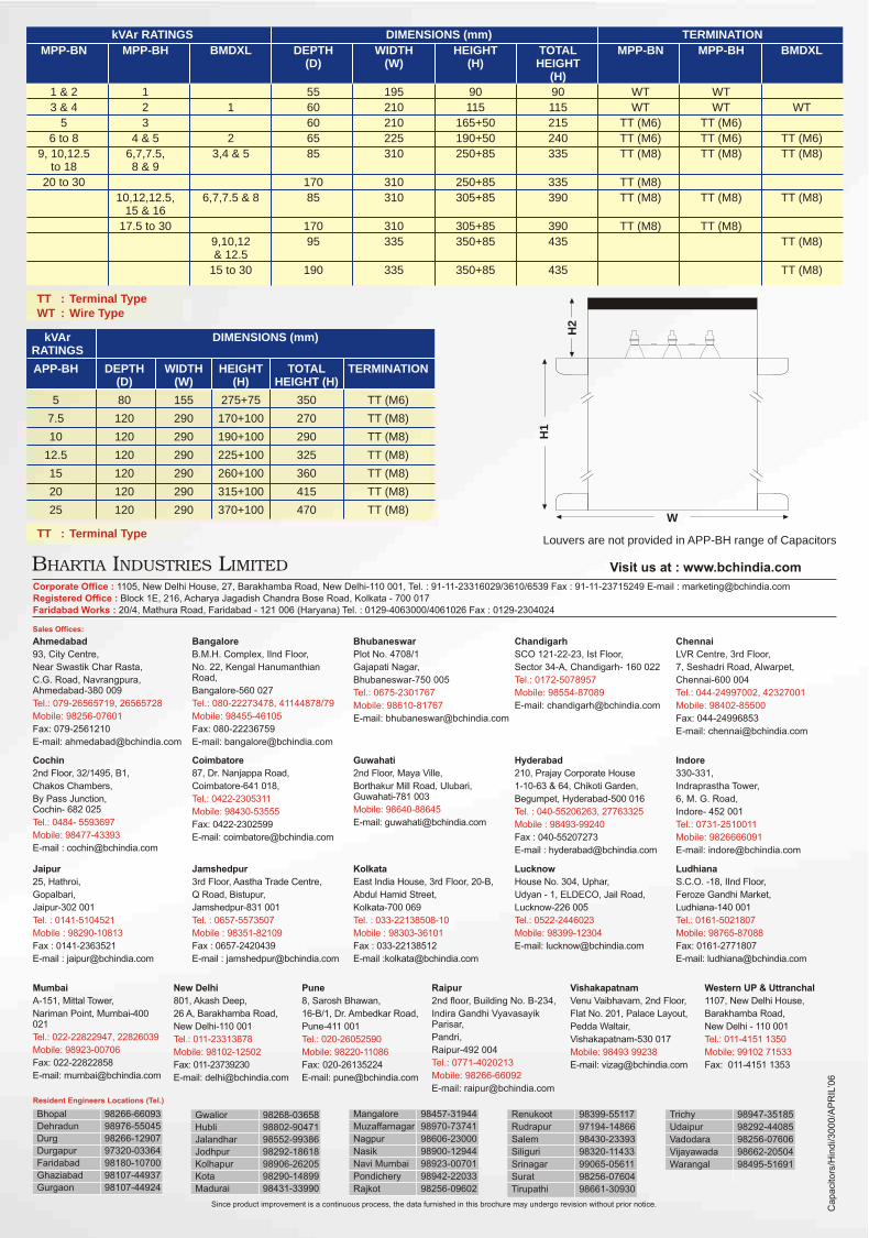
TT : Terminal Type
TT : Terminal TypeWT : Wire Type
H1
H2
W
Louvers are not provided in APP-BH range of Capacitors
kVAr RATINGS DIMENSIONS (mm) TERMINATION
MPP-BN MPP-BH BMDXL DEPTH WIDTH HEIGHT TOTAL MPP-BN MPP-BH BMDXL(D) (W) (H) HEIGHT
(H)
1 & 2 1 55 195 90 90 WT WT
3 & 4 2 1 60 210 115 115 WT WT WT
5 3 60 210 165+50 215 TT (M6) TT (M6)
6 to 8 4 & 5 2 65 225 190+50 240 TT (M6) TT (M6) TT (M6)
9, 10,12.5 6,7,7.5, 3,4 & 5 85 310 250+85 335 TT (M8) TT (M8) TT (M8)to 18 8 & 9
20 to 30 170 310 250+85 335 TT (M8)
10,12,12.5, 6,7,7.5 & 8 85 310 305+85 390 TT (M8) TT (M8) TT (M8)15 & 16
17.5 to 30 170 310 305+85 390 TT (M8) TT (M8)
9,10,12 95 335 350+85 435 TT (M8)& 12.5
15 to 30 190 335 350+85 435 TT (M8)
kVAr DIMENSIONS (mm)RATINGS
APP-BH DEPTH WIDTH HEIGHT TOTAL TERMINATION(D) (W) (H) HEIGHT (H)
5 80 155 275+75 350 TT (M6)
7.5 120 290 170+100 270 TT (M8)
10 120 290 190+100 290 TT (M8)
12.5 120 290 225+100 325 TT (M8)
15 120 290 260+100 360 TT (M8)
20 120 290 315+100 415 TT (M8)
25 120 290 370+100 470 TT (M8)