Embed Size (px)
Citation preview

Series GR Page 1 LT094 Feb 2019
Installation, Operation and Service Instructions
INFRARED HEATERS
SERIES
GR
WARNING FOR YOUR SAFETY
Improper installation, adjustment, alteration, service or maintenance can cause property damage, injury or death. Read the installation, operation and maintenance instructions thoroughly before installing or servicing this equipment.
Do not store or use flammable vapors and liquids in the vicinity of this or any other appliance. If you smell gas: 1. Open windows 2. Don’t touch electrical switches 3. Extinguish any open flame 4. Immediately call your gas supplier
OWNER INSTALLER
Retain this Manual & ensure available for Service.
Improper installation, adjustment, alteration, service or maintenance can cause injury, death or property damage.
Read the installation, operation and service instructions thoroughly before installing or servicing this equipment.
Provide Manual to Owner upon completion of installation!
Read and thoroughly understand these Instructions before attempting any installation
Note: Not For Installation in Mobile Homes or Recreational Vehicle.
Canada: 563 Barton Street, Stoney Creek, Ontario L8E 5S1 USA: 315 N Madison Street, Fortville, IN 46040
www.superiorradiant.com

Series GR Page 2 LT094 Feb 2019
CAUTION: FIRE OR EXPLOSION HAZARD
Maintain clearance to combustible materials as further specified in this manual. Failure to do so could result in a serious fire hazard. Heaters should not be located in hazardous atmospheres containing flammable vapors or combustible dusts. Signs should be provided in storage areas specifying maximum safe stacking height.
CAUTION: MECHANICAL HAZARD
This equipment expands and contracts with each operating cycle. The gas connection, suspension hardware and the installation itself must safely allow this movement. Failure to do so could result in serious fire or explosion hazard.
CAUTION: FIRE OR EXPLOSION HAZARD
This heater is equipped with an automatic ignition device. Do not attempt to light the burner by hand. Failure to comply could result in a serious fire and personal injury hazard.
CAUTION: MECHANICAL HAZARD
Do not use high pressure (above 1/2 psi) to test the gas supply system with the burners connected. Failure to do so could result in damage to the burner and its control components requiring replacement.
CAUTION: SERVICE LIFE RISK
Do not install equipment in atmospheres containing halogenated hydrocarbons or other corrosive chemicals. Failure to do so may lead to premature equipment failure and invalidation of the warranty. Additionally, it is recommended that the equipment be installed with a slope downward and away from the burner of ¼" inch in 10' feet to allow start-up condensate drainage.

Series GR Page 3 LT094 Feb 2019
Table of Content Table of Content ................................................................................................................................................................ 2
Introduction ....................................................................................................................................................................... 4
Installation Codes........................................................................................................................................... 4
General Specifications ........................................................................................................................................................ 6
Gas Supply ..................................................................................................................................................... 6 Inlet Pressure ........................................................................................................................................................................ 6 Manifold Pressure ................................................................................................................................................................. 6 Inlet Connection ................................................................................................................................................................... 6
Electric Supply ................................................................................................................................................ 6
Heater Specifications ..................................................................................................................................... 6
Venting .......................................................................................................................................................... 6
Clearance to Combustibles ................................................................................................................................................. 7
Installation Detail .............................................................................................................................................................. 9
Installation Sequence ..................................................................................................................................... 9
Outdoor Installation ...................................................................................................................................... 10
Cover Installation Sequence .......................................................................................................................... 12
Venting / Combustion Air Ducting ..................................................................................................................................... 14
General Requirements .................................................................................................................................. 14
Optional Horizontal Elbow Vent Terminal ..................................................................................................... 16
Roof Venting ................................................................................................................................................. 17
Gas Piping ......................................................................................................................................................................... 18
General Requirements .................................................................................................................................. 18
Electrical Wiring ................................................................................................................................................................ 19
General Requirements .................................................................................................................................. 19
Operation / Maintenance .................................................................................................................................................. 20
Starting Sequence of Operation .................................................................................................................... 20
Maintenance ................................................................................................................................................. 20
Trouble Shooting ............................................................................................................................................................... 21
Troubleshooting Chart .................................................................................................................................. 22
Replacement Parts ............................................................................................................................................................ 23
Warranty .......................................................................................................................................................................... 24

Series GR Page 4 LT094 Feb 2019
Important These instructions, the layout drawing, local codes and ordinances, and applicable standards such as apply to gas piping and electrical wiring comprise the basic information needed to complete the installation, and must be thoroughly understood along with general building codes before proceeding. Only personnel who have been trained and understand all applicable codes should undertake the installation. SRP Representatives are Factory Certified in the service and application of this equipment and can be called on for helpful suggestions about installation.
Introduction Superior Radiant Products is a company in the infrared heating industry founded on the principles of product quality and customer commitment. Quality commitments are evidenced by superior design, a regard for design detail and an upgrade of materials wherever justifiable. Customer commitment is apparent through our ready responses to market demands and a never ending training and service support program for and through our distributor network.
Installation Codes
Installations must comply with local building codes, or in their absence, the latest edition of the national regulations and procedures as listed below.
General Installation and Gas Codes
Heaters must be installed only for use with the type of gas appearing on the rating plate, and the installation must conform to the National Fuel Gas Code, ANSI Z223.1/NFPA 54 in the USA and CSA B149.1 and B149.2 Installation Codes in Canada.
This heater maybe approved for either indoor or outdoor installation. Not for use in residential dwellings, refer to Rating plate. Aircraft Hangar Installation
Installation in aircraft hangars must conform to the Standard for Aircraft Hangars, ANSI/NFPA 409 in the USA and CSA B149.1 and B149.2 Installation Codes in Canada.
Public Garage Installation
Installation in public garages must conform to the Standard for Parking Structures, NFPA-88A or Standard for Repair Garages, NFPA 88B, in the USA and CSA B149.1 and B149.2 Installation Codes in Canada.
Parking Structures
Technical requirements are outlined in ANSI/NFPA 88B (USA)
Gas Supply Lines
The appliance must be isolated from the gas piping system by closing equipment shutoff valve during any pressure testing of the gas supply piping system at test pressures equal to or less than ½ psi (3.45 kPa)

Series GR Page 5 LT094 Feb 2019
Electrical
All heaters must be electrically grounded in accordance with the National Electric Code, ANSI/NFPA 70 in the USA and the Canadian Electric Code, CSA C22.1 in Canada, and must comply with all local requirements.
Venting
Refer to the National Fuel Gas Code, ANSI Z223.1 (NFPA 54) in the USA and CSA B149.1 and B149.2 Installation Codes in Canada for proper location, sizing and installation of vents as well as information on clearance requirements for conventional venting methods. See page 11 for horizontal venting requirements.
This appliance shall not be connected to a chimney flue serving a separate solid-fuel burning appliance.
High Altitude
When installing this appliance over 4500 ft. above sea level in Canada, the appliance must be properly de-rated and installed according to local codes. In the absence of local codes the appliance must be de-rated in accordance with the most recent CSA - B149 code.
In the United States for installations over 2000ft above sea level the appliance must be installed in accordance with the Current National Fuel Gas Code, ANSI Z223.1/NFPA 54.
Safety Features
This heater utilizes an airflow switch as blocked vent shut off system. This system is designed to prevent the operation of the appliance if a fresh air supply is blocked or if the flue exhaust is blocked. If this system fails to operate DO NOT ATTEMPT ADJUSTMENTS. Disconnect power to the appliance and contact a qualified service person.

Series GR Page 6 LT094 Feb 2019
General Specifications
Gas Supply
Electric Supply 120 VAC, 60 Hz, 1 Amp: Heater includes a 36" power cord with grounded 3 prong plug.
Heater Specifications Input: Model GR-30: 30,000 BTU/h Model GR-45: 45,000 BTU/h
Weight: Model GR-30: 100 lbs (45 Kg) Model GR-45: 100 lbs (45 Kg)
Venting Horizontal venting: Maximum air vent / flue for either rate is 10' feet
Roof Venting: Refer to ANSI Z223.1 and CSA B149.1 and B149.2 fan assisted appliances for correct sizing.
Flue Dia.: 2" diameter (installed concentrically)
Note: The heater includes a horizontal vent installation kit. The kit contains all components necessary to vent the heater horizontally and is required. See page 11.
A vertical vent kit is available as an alternate venting method. This Kit Part # RS022 is available through SRP distributors and contains the appropriate adapters to allow the connection of B-vent material. See roof-venting page 13.
Figure 1: Overall Dimensional Information
Inlet Pressure
Natural Gas: Min. 5.0" W.C. Propane Gas: Min. 11.5" W.C. Max. 14.0" W.C. Max. 14.0" W.C. Manifold Pressure
Natural Gas: 3.5" W.C. Propane Gas: 10.5" W.C. Inlet Connection
Natural Gas or Propane Gas: 1/2" NPT. Female
6.45.4
113.0 1.0
1.83.8
7.5
15.1

Series GR Page 7 LT094 Feb 2019
Clearance to Combustibles It is very important to observe the minimum clearance to combustibles at all times to avoid any possibility of property damage or personal injury. WARNING Clearances as marked on the heater body must be maintained from vehicles parked beneath. Signs should be posted identifying any possible violation of the clearance distances from the heater in all vehicle areas. Maximum allowable stacking height in storage areas should be identified with signs or appropriate markings adjacent to the thermostat or in a conspicuous location. Table 1 lists the minimum clearance to combustible materials for various installation configurations. Additional clearance may be required for glass, painted surfaces and other materials which may be damaged by radiant or convective heat. Combustible materials are considered to be wood, compressed paper, plant fibres, plastics, Plexiglas or other materials capable of being ignited and burned. Such materials shall be considered combustible even though flame-proofed, fire-retardant treated or plastered. The stated clearance to combustibles represents a surface temperature of 90°F (50°C) above room temperature. Building materials with low heat tolerance (such as plastics, vinyl siding, canvas, tri-ply, etc…) maybe subject to degradation at lower temperatures. It is the installer’s responsibility to assure that adjacent materials are protected from degradation. It is important to observe minimum clearance to combustibles at all times to avoid any possibility of property damage or personal injury. Clearances must be maintained from vehicles parked beneath heaters. Signs should be posted identifying any possible violation of the clearance distances from the heater in vehicle areas. Also maximum allowable stacking height in storage areas should be identified with signs or appropriate markings. Figure 2 shows minimum clearance to combustible materials.
Configuration Dimension 30,000 BTU/h 45,000 BTU/h
Standard
A
B
C
D
2˝
18˝
36˝
18˝
2˝
18˝
50˝
18˝
45° Tilt
A
B
C
D
2˝
2˝
33˝
33˝
3˝
3˝
48˝
48˝
Vented End 5” 5”
Table 1: Clearance to Combustible Table

Series GR Page 8 LT094 Feb 2019
Figure 2: Clearance to Combustible Diagram
CAUTION In all cases, the minimum hanging height from the floor shall be:
In Canada: 7' feet In USA: 8' feet
C
B
A
45°
C
B
D
D
A

Series GR Page 9 LT094 Feb 2019
Installation Detail
Installation Sequence The heater is sent with all parts necessary for installation with the exception of chain.
It is recommended that the heater be hung as high as possible and along an uncluttered wall to give the reflector a widest possible “view” of the space to be heated. Avoid installation directly over vehicle parking, over cabinets, or where an open door will interfere. Adhere to minimum clearances on the rating plate.
Leave adequate space around the burner box for future servicing.
Choose a location that permits easy installation of exterior venting. A horizontal vent length up to 10' feet is allowed. For vertical venting adhere to local venting tables and methods.
Figure 3: General Overview of Components Utilized in the Installation
As required, fasten hanging angles to ceiling such that heater-hanging points can be accommodated.
Each hanging point must be able to hold at least 150 lbs.
Allow for movement of heater during expansion and contraction during operating cycle.
Heater must fire horizontally. To tilt reflector at 45°, lengthen two of the hanging points to an appropriate length using chain. (Each chain length will be approximately 12" inches longer than the high side of the heater). SRP recommends and make available “quick links” for connecting chain. If any open ended “S” hooks and turnbuckles are used, the open ends must be closed to avoid unhooking chain with inadvertent contact.
96.00"
Fasten Support Angle to Ceiling toAccommodate Heater Hanging Points
OR
Note:Close all open ended "S" hooks, chain links,and turnbuckles or any open connection.

Series GR Page 10 LT094 Feb 2019
Outdoor Installation For outdoor installations the heater must be installed not more than 8" from beneath awnings and not less than 24" from back and side as shown in Figure 4. If the heater cannot be protected from the elements by an overhang, then a protective cover must be installed as shown in Figure 7, Figure 8 and Figure 9.
Figure 4: Outdoors Heater Installation
When the heater is installed with back and side dimensions greater than the minimum of 24" then the top dimension may be increased. The new maximum Top dimension is 1/3 of the smallest side or back clearance. Example: Given: Side dimension = 36" Back dimension = 48" A ratio of 3:1 must be maintained The side dimension gives us a maximum Top dimension of (36/3)" = 12" The back dimension gives us a maximum Top dimension of (48/3)" = 16" The new Top dimension is 12", the lesser of the two.
24"24"
SIDE
BACK
TOP 8"
Note:Close all open ended "S" hooks, chain links,and turnbuckles or any open connection.

Series GR Page 11 LT094 Feb 2019
Figure 5: Mounting Distances for Outdoor Installations under Eaves.
Figure 6: Mounting Distances for Tilted (45°) Outdoor Installations under Eaves.
In the case where the heater is installed at a 45° angle, the minimum dimension inside the overhang is 28" from both the back and side of the burner box and 8" maximum on the top. If the side or back dimensions are increased then the top clearance may be increased using the same rules as for a horizontal installation.
NOTE: These dimensions are only for satisfying outdoor heater positioning. Clearance to combustible must also be satisfied.
24.00" Min. or ("B")8.39" or ("B/3") Max.
28.00" Min. or ("B")8.00" Max. or ("B/3")
28.00" Min. or ("B")8.00" Max. or ("B/3")

Series GR Page 12 LT094 Feb 2019
When a heater is installed outdoors without the presence of an adequate eave, then a protective cover must be installed as illustrated below. This cover is available from your local dealer (Part # RS020).
Cover Installation Sequence
Install support brackets on to heater covers as shown in step 1 in Figure 7. Pre-assemble the cover and its top covers and bottom cover as shown in step 2 in Figure 7. Remove the two top screws holding the reflector in place. Slide cover onto burner making sure the support brackets slide into slots on the bottom cover. Secure cover to heater by screwing in the cover bracket in step 3B in Figure 8. Install the extension covers (Front, Back, and Side) as shown in step 4 in Figure 8 if needed.
Figure 7: Cover Installation Sequence Steps 1 and 2
When a heater is to be installed outdoors at 45° without the presence of an adequate eave, an extension cover must be used to protect the heater, refer to step 4 in Figure 8. This extension cover is available through your local SRP Dealer (Part # RS021). Note that both the cover and extension cover must be used in this case.
Figure 8: Cover Installation Sequence Steps 3 to 5
Cover
2
Right SupportBracket, InstallScrew onBottom Hole
Left SupportBracket, InstallScrew onTop Hole
1Install BothTop CoversAs Shown,Then InstallAssembly onto Heater
Install BottomCover As Shown
Back
Side
Front
5
43
Install 45°Extension
CoversAs Shown
Attach CoverBracket
3
A
B
Note:Close all open ended "S" hooks, chain links,and turnbuckles or any open connection.

Series GR Page 13 LT094 Feb 2019
Figure 9: Extension Cover for 45° Outdoor Installations
Extension Cover
Note:Close all open ended "S" hooks, chain links,and turnbuckles or any open connection.

Series GR Page 14 LT094 Feb 2019
Venting / Combustion Air Ducting
General Requirements Refer to the National Fuel Gas Code, ANSI Z223.1 (NFPA 54) in the USA and CSA B149.1 and B149.2
Installation Codes in Canada, as well as all local requirements for vertical venting and general guidance for minimum distances to openings to the building.
This equipment is of balanced flue construction and must be horizontally vented (see
Figure 10). Vertical venting is permitted, but not as a balanced flue assembly. (See roof venting)
Figure 10: Various Venting Orientations
A flue/air vent length of 8 feet or less is recommended, although a maximum of 10' feet is allowable (including one elbow).
An approved Wall Terminal that allows the air duct to pass through the wall is required. This is included with your heater. The Wall Terminal is a zero clearance terminal for both combustible and non-combustible walls.
For horizontal venting where an elbow is utilized an elbow kit (Part No. RT013) must be used, refer to Figure 10 for more details.
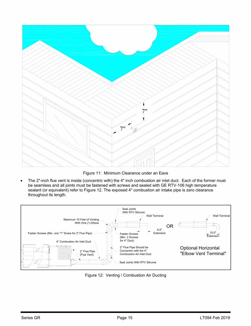
The 2" inch flue pipe should extend a minimum of 6" inches beyond the end of the 4" inch wall terminal (for horizontally vented heaters only see Figure 12). Where the vent is under an eave the 2" vent pipe must have a minimum clearance of 7" from the centerline of the vent to the bottom of the eave, refer to
Figure 11. However, when the 2" pipe is less than 18" from the bottom of the eave, we recommend the 2" inch flue extend just beyond the eave to prevent the possibility of frost. (Adhere to any code requirements for clearances to opening in the building).
An optional “Horizontal Elbow Vent Terminal” kit for horizontal venting is also available; refer to Figure 12 and Figure 13.
Wall Thickness(Max. 10")
(Min. 1")
NOTES:1- This Heater may be rotated at 45° Tilt, but both ends of the heater must be kept at the same elevation.2- Total Vent Length (Including One (1) Elbow) = 10' Each Additional Elbow = 4' Max. Number Of Elbows = 2
Wall TerminalP/N RS006
Wall Thickness(Max. 10")
(Min. 1")
Ø4" CombustionAir Inlet Duct
Ø2" FluePipe
Wall TerminalP/N RS006
Wall TerminalP/N RS006
Wall Thickness(Max. 10")
(Min. 1")
Ø4" CombustionAir Inlet Duct
Ø2" Flue Pipe
Ø4" CombustionAir Inlet Duct
Ø2" Flue Pipe
Heater may be sloped 14" in 10 '
Vent Elbow KitP/N RT013
Vent Elbow KitP/N RT013
6 6 6
Series GR Page 15 LT094 Feb 2019
Figure 11: Minimum Clearance under an Eave
The 2"-inch flue vent is inside (concentric with) the 4" inch combustion air inlet duct. Each of the former must be seamless and all joints must be fastened with screws and sealed with GE RTV-106 high temperature sealant (or equivalent) refer to Figure 12. The exposed 4" combustion air intake pipe is zero clearance throughout its length.
Figure 12: Venting / Combustion Air Ducting
7"
7"
Fasten Screws (Min. one "1" Screw for 2" Flue Pipe)
2" Flue Pipe(Flue Vent)
4" Combustion Air Inlet Duct
Maximum 10 Feet of VentingWith One (1) Elbow
2" Flue Pipe Should beConcentric with the 4"Combustion Air Inlet Duct
Seal Joints With RTV Silicone
Fasten Screws(Min. 2 Screwsfor 4" Duct)
Seal JointsWith RTV Silicone
6.0"Extension
Wall Terminal
OR10.0"
Extension
Wall Terminal
Optional Horizontal"Elbow Vent Terminal"

Series GR Page 16 LT094 Feb 2019
Optional Horizontal Elbow Vent Terminal
The GR Models are approved to be used with an Elbow as a Horizontal Vent Terminal see Figure 13 for installation details.
Figure 13: Optional Horizontal Elbow Vent Terminal / Installation.

Series GR Page 17 LT094 Feb 2019
Roof Venting When heater is to be vented through a roof (Vertical Venting) this heater is considered as a Category I appliance, a B-Vent adapter kit (Part # RS022) must be used. The B-vent must be installed in accordance to the National Fuel Gas Code, ANSI Z223.1 (NFPA 54) in the USA and CSA B149.1 and B149.2 Installation Codes in Canada. Refer to the former for correct sizing. Refer to Figure 14 for general overview. Combustion air may be supplied from the outdoors using the material provided in the vent adapter kit (Part # RS022) available from your local dealer. Maximum length of fresh air is 10 feet including one elbow. Fresh air ducting is not provided in the kit.
Figure 14: Roof Venting / Combustion Air Ducting
The B-vent adapter must be secured with screws and sealed with high temperature silicone sealant. Install B-vent as per local code requirements.
Vertical Vent KitP/N RS022
For Vertical Venting Refer ToANSI Z223.1 and CAN/CSA B149.1
and B149.2 for Fan Assisted Appliancesfor Correct Sizing, Clearance and
Penetration Requirements.
B-VentAdapter
4" CombustionAir Inlet Duct
4" Fresh Air Terminal(included in vertical vent kit)
B-VentFlue Pipe(Flue Vent)

Series GR Page 18 LT094 Feb 2019
Gas Piping
General Requirements
The gas meter and service must be sufficiently large to supply gas to the connected building gas load including the heating equipment and any other gas-fired equipment. Additionally, the gas distribution piping must be designed according to local and national ordinances. Generally (low pressure) systems designed with a maximum 1/2"-inch W.C. total pressure drop meet this requirement.
Gas supply pipe sizing must be in accordance with the National Fuel Gas Code, ANSI Z223.1 (NFPA 54) in the USA and CSA B149.1 and B149.2 Installation Codes in Canada.
Before connecting burners to the gas supply system, verify that high pressure testing of the system has been completed. Failure to do so may expose the burner components to damaging high pressure, requiring replacement of key components.
Flexible gas connectors of approved type must be installed as shown in Figure 15, in one plane, and without sharp bends, kinks or twists. A smooth loop of approximately 12" inches in diameter is best. Failure to install the gas connection in the approved manner will result in a hazardous and potentially deadly situation due to the movement of the heat exchanger and burner in the normal course of operation.
Figure 15: Flexible Gas Connection
3" (7.62 cm) Max.Displacement
12"(30 cm)
Heater Movement Vertical(As Shown Below)
AlternatePositions
Okay
CORRECT POSITIONS
INCORRECT POSITIONS
WRONG
WRONG WRONG
WRONG
Heater Movement
HeaterMovement
Heater Movement
HeaterMovement

Series GR Page 19 LT094 Feb 2019
Electrical Wiring
General Requirements Heaters are normally controlled with the thermostat that is included with your equipment. A 24V signal is supplied by the heater control module for thermostat connection. Refer to wiring diagram, Figure 16. A bulkhead fitting in the back panel of the control box is provided for the appropriate wire. In all cases, heaters must be grounded in accordance with the National Electric Code, ANSI/NFPA 70 in the USA, and the Canadian Electric Code, CSA C22.1 in Canada, and must comply with all local requirements.
If any of the original wire as supplied with the heater must be replaced, it must be replaced with wiring having a rating of at least 105°C temperature service and 600 volts capability.
Figure 16: Internal Wiring

Series GR Page 20 LT094 Feb 2019
Operation / Maintenance
Starting Sequence of Operation Turn the thermostat up. When the thermostat calls for heat, the blower motor will energize.
When the motor approaches nominal running RPM, the air-proving switch closes and activates the ignition
module.
The ignition module, after a pre-purge period of approximately 30 seconds, energizes the igniter.
Additionally, the gas valve is energized for this ignition trial period of 15 seconds.
If a flame is detected, the ignition sensing rod "reads" a rectification signal and the gas valve remains open.
The sparking stops when the flame signal is established.
If no flame is detected, the gas valve closes and a 30 sec inter-purge period begins. After the inter-purge, the
module repeats the trial for ignition period. If flame is still not established, a third and final inter-purge followed
by a final ignition trial cycle begins. After three trials, the module will lockout for a period of approximately 1
hour or until reset. (Reset is accomplished by removing power from the module for at least 5 seconds.) After
this 1-hour period, the module re-attempts the full ignition sequence.
When using a 24V thermostat and the heat requirement has been met and the thermostat opens, the burner
shuts off but the fan continues to run for approximately 30 seconds. This is referred to as a post purge. This
allows the products of combustion to be removed from the heat exchanger to avoid nuisance condensation
and increase heat exchanger life.
When using a line voltage thermostat and the heat requirement has been met and the thermostat opens, the
burner and fan shut off with no post purge.
Maintenance For best performance, the following minimal maintenance procedures should be performed before each heating season:
Before performing any service or maintenance, shut off gas and electrical supply to heater.
Check condition of forced air blower scroll and motor. Dirt and dust may be blown or vacuumed from the
blower.
Check condition of burner. Remove any foreign objects or debris from inside the burner box or burner cup.
Inspect the igniter. Replace igniter if there is excessive wear or erosion, breakage or other defects.
Check inside the heat exchanger tube visually with a flashlight. If carbon or scale are present, scrape or
otherwise remove deposits (a wire brush works well).
Be sure the burner observation window is clean and free of cracks or holes. Clean or replace as necessary.
Check the flue pipe for soot or dirt and reattach to the heater after cleaning as necessary.
The heat exchanger reflector sections may be cleaned by wiping with a damp cloth.
A service agency qualified to adjust and repair infrared heaters should be engaged for service other than
routine maintenance.
Be sure vent terminal and fresh air inlet are free from obstructions. If either pipe is restricted, the safety air
switch will not operate properly, and the heater could fail to operate.

Series GR Page 21 LT094 Feb 2019
Trouble Shooting
Blower Motor Fails to Run
Is the thermostat calling for heat? Is there 115V at the burner receptacle? Check blower side door for seal. Repair as necessary. Check blower for obstructions. Replace blower if necessary.
No Gas Supply
Check to see if manual supply valve to heater is ON. Check to see if gas valve knob on heater gas control is ON. Supply gas pressure can be checked at 1/8" NPT pressure tapping in gas supply system. Is combination gas control opening? No manifold pressure indicates valve is closed. Gas pressure
downstream of gas control can be measured by connecting a manometer to pressure tap on control. If the valve is closed, either the gas valve or the ignition module is faulty.
Burner Does Not Light
Is spark visible through site glass during ignition trial? If no, further electrical checks by a qualified service person are probably necessary.
Check to see if gas lines were properly purged of air. Check inlet and outlet gas pressure during ignition period. Check for orifice and air plate obstruction.
Burner Does Not Stay Lit
Check ground wire continuity. Check insulation on the igniter leads. Measure flame signal current; it should be above 0.8 micro amps DC. Replace module if necessary.

Series GR Page 22 LT094 Feb 2019
Troubleshooting Chart
Rep
lace
Mod
ule
ifno
pow
er
to M
otor
IF P
RO
BLE
M P
ER
SIS
TS
CO
NT
AC
T Y
OU
R L
OC
AL
SR
P R
EP
RE
SE
NT
AT
IVE
YE
S
NO
Rec
tify
As
Req
uire
d
Ver
ify S
ense
Ele
ctro
deV
erify
Gro
und
Ver
ify W
iring
Doe
s 24
V O
ccur
At
Val
ve D
urin
gIg
nitio
n T
rial?
Che
ckW
iring
and
Rec
tify
As
requ
ired
Che
ck E
lect
rode
Gap
Set
to 1
/8"
Che
ck 1
20V
Pow
erV
erify
at M
otor
Is G
as P
rese
nt A
tV
alve
? Is
Gas
Pre
ssur
e S
uffic
ient
?
Is T
here
A F
lam
eS
igna
l To
Mod
ule?
Min
. 0.8
Mic
ro A
mps
Rec
tify
As
Req
uire
d
Bur
ner
Sta
ysLi
t?
YE
S
Bur
ner
Ligh
ts?
YE
S
NO
NO
YE
S
NOYE
S
Che
ck Ig
nitio
n W
ireR
epla
ce If
Da
mag
ed
Che
ck T
herm
osta
tR
epla
ce If
Req
uire
d
Doe
sE
lect
rode
Spa
rk?
YE
S
YE
SBlo
wer
Sta
rts?
NO
NO
YE
SIs
Val
ve In
On
Pos
ition
?
YE
S
Rep
lace
Mot
or If
Req
uir
ed
Is P
ress
ure
Sw
itch
Ope
ratin
g?
Rep
lace
Igni
tion
Con
trol
Mod
ule
YE
S
Unp
lug
Mot
orD
oes
Mo
tor/
Impe
ller
Spi
n F
reel
y?
Rec
tify
As
Req
uire
d
TR
OU
BLE
SH
OO
TIN
G C
HA
RT
Tur
n U
pT
herm
osta
t
Rep
lace
Val
ve
Che
ck A
ir L
ines
To
Sw
itch
Che
ck B
urn
er S
yste
mF
or O
bstr
uctio
n
Che
ck F
or 2
4V A
tS
witc
hR
ectif
y T
rans
form
er O
rW
iring
As
Req
uire
d

Series GR Page 23 LT094 Feb 2019
Replacement Parts
Figure 17: Replacement Parts
ITEM # PART # DESCRIPTION ITEM # PART # DESCRIPTION
1 CE010 Power Cord 5 CE011 Blower Motor
2 CE158 45,000 BTU Pressure Switch 6 CH011 Sight Glass Assy
CE160 30,000 BTU Pressure Switch 7 CE003 Flame Sensor
3 RG021 Valve Train - Natural - Honeywell 8 RE019 Ignitor
RG022 Valve Train - Propane - Honeywell Not Shown CE008 Transformer
4 CE015 Ignition Module Not Shown CE006 Ignition Wire

Series GR Page 24 LT094 Feb 2019
Warranty
SERIES GR INFRARED HEATERS
WARRANTY The Manufacturer warrants to the original owner that the product will be free of defects in material and workmanship. This warranty is limited to 36 months from the date of installation for all components. The Manufacturer’s obligation under this warranty is limited to repair or replacement, F.O.B. the factory, of the defective part. In the case of replacement parts, the warranty period shall be the longer of the original warranty or a period of 12 months from the date of purchase. In no event shall the Manufacturer be liable for incidental expense or consequential damages of any kind. This warranty does not cover any shipping, installation or other costs incurred in the repair or replacement of the product. No materials will be accepted for return without authorization. This warranty will not apply, if in the judgment of the Manufacturer, the equipment has been improperly installed, unreasonably used, damaged or modified. This warranty will not apply to damage to the product when used in corrosive atmospheres and in particular atmospheres containing halogenated hydrocarbons. No person is authorized to assume for the Manufacturer, any other warranty, obligation or liability.
THE REMEDIES PROVIDED FOR IN THE ABOVE EXPRESS WARRANTIES ARE THE SOLE AND EXCLUSIVE REMEDIES. NO OTHER EXPRESS OR IMPLIED WARRANTIES ARE MADE INCLUDING, BUT NOT LIMITED TO, ANY IMPLIED WARRANTY OF MERCHANT ABILITY OR FITNESS FOR A PARTICULAR USE OR PURPOSE.
Address questions to your local distributor/ or Superior Radiant Products Ltd
Stoney Creek, Ontario
1-800-527-4328
Heater Series :_______________
Installed Rate :_______________Btu/Hr
Serial Number :_______________
Installed Date :_______________


![arXiv:1501.06524v2 [gr-qc] 25 Feb 2015 the generalized](https://img.pdfslide.net/doc/110x75/61d446fc867b877f495d33fb/arxiv150106524v2-gr-qc-25-feb-2015-the-generalized-.jpg)