Embed Size (px)
Citation preview

M
LT300 Series Earth Loop Testers
USER MANUAL
LT300_UG_en_V01 07/05/2004 9:38 am Page 1

G SAFETY WARNINGS
Safety Warnings and Precautions must be read and understood before the instrument is used. They must be observed during use.
Continuity of protective conductors and earthed equipotential bonding of new or modified installations must be verified before carrying out an earth
fault loop impedance or RCD tests.
Do not leave the instrument connected to the mains supply when not in use.
Circuit connections and exposed metalwork of an installation or equipment under test must not be touched.
Ensure that hands remain behind guards of probes/clips when testing.
The instrument should not be used if any part of it is damaged.
Test leads, probes and crocodile clips must be in good order, clean and with no broken or cracked insulation.
National Safety Authorities may recommend the use of fused test leads when measuring voltage on high-energy systems.
The battery cover must be in place whilst conducting tests.
Voltage indicator LED’s cannot reveal a N-PE supply reversal.
When making a 2 wire measurement with the 3 wire lead set, for safety reasons the balck test lead should be connected together with the green test
lead.
2
Users of this equipment and/or their employers are reminded that Health and Safety Legislation requires them to carry out valid risk assessments of all
electrical work so as to identify potential sources of electrical danger and risk of electrical injury such as inadvertent short circuits.
Some national safety authorities recommend fused leads for voltage measurement on high energy systems. If RCD or Loop tests are made it may cause
the fuse to rupture, and so they must be used with caution on voltage testing.
NOTETHE INSTRUMENT MUST ONLY BE USED BY SUITABLY TRAINED AND COMPETENT PERSONS.
LT300_UG_en_V01 07/05/2004 9:38 am Page 2

Frequency Hz (LT320 only) 16
Phase sequence (LT320 only) 16
Replacing batteries and fuses 17
Low battery warning symbol 17
To replace batteries 17
Fuse blown indication 17
Auto power down 18
Preventive maintenance 18
Technical specification 19
Basic and service errors 21
Accessories and equipment 21
Repair and Warranty 22
Symbols used on the instrument are:
G Caution: refer to accompanying notes
t Equipment protected throughout by Double
Insulation (Class II)
c Equipment complies with current EU directives.
Equipment complies with ‘C tick’ requirements
CONTENTS
3
Safety warnings 3
Introduction 4
General description 5
Unpacking the carton 7
LCD Display 6
Front Panel 6
Connection panel 7
Lid open/closure 7
Preparations for use 8
Batteries 8
Preliminary test lead check 8
General operating instructions 8
Display warning symbols 8
Setup Procedure 9
Reverse polarity or line/neutral swapping 9
Test Leads 9
Test lead connection. 10
LED indicators 10
Loop testing 11
Non-tripping loop test [No Trip] 11
Hi current loop test [Hi] 11
Phase-Earth loop impedance (not at a power socket): 12
Phase-Neutral or Phase-Phase loop impedance 12
Prospective Fault current display [PFC] 12
Error messages 12
Possible sources of error 13
maxZ (LT320 only) 14
Deriving R1 + R2 (LT320 Only) 14
Voltage measurement 15
Phase to Earth voltage measurement 15
Phase to Phase voltage measurement (LT320 only) 15
N13117
LT300_UG_en_V01 07/05/2004 9:38 am Page 3
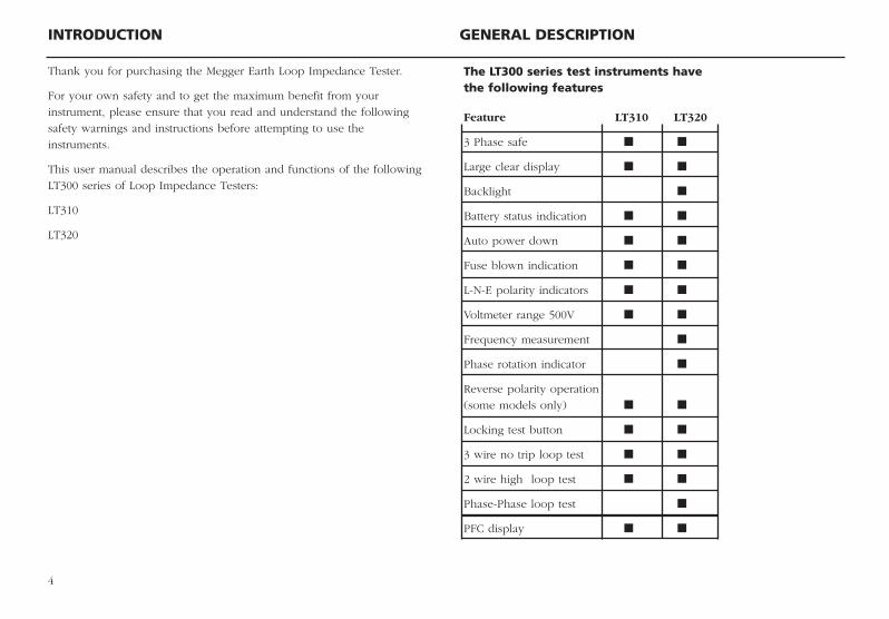
Feature LT310 LT320
3 Phase safe
Large clear display
Backlight
Battery status indication
Auto power down
Fuse blown indication
L-N-E polarity indicators
Voltmeter range 500V
Frequency measurement
Phase rotation indicator
Reverse polarity operation
(some models only)
Locking test button
3 wire no trip loop test
2 wire high loop test
Phase-Phase loop test
PFC display
INTRODUCTION GENERAL DESCRIPTION
4
Thank you for purchasing the Megger Earth Loop Impedance Tester.
For your own safety and to get the maximum benefit from your
instrument, please ensure that you read and understand the following
safety warnings and instructions before attempting to use the
instruments.
This user manual describes the operation and functions of the following
LT300 series of Loop Impedance Testers:
LT310
LT320
The LT300 series test instruments havethe following features
LT300_UG_en_V01 07/05/2004 9:38 am Page 4

Unpack the carton contents carefully. There are important documents
that you should keep for future reference.
Please complete the pre-paid warranty card and return it to Megger as
soon as possible to help us reduce any delays in supporting you should
the need arise.
Carton contents LT310 and LT3201 x LT300 series insulation tester
1 x 3 wire test lead with prods with clips
8 x AA (LR6) batteries (fitted in instrument)
1 x Test lead case
1 x Warranty card
1 x Certificate of test
1 x Calibration certificate
1 x Owner’s CD manual
1 x Safety instructions
UNPACKING THE CARTON
5
Feature LT310 LT320
Max Zs display
R1+R2/ZRef switch
Plug ended test lead
3 wire ended test lead
probe/croc clip ended
Calibration Certificate
IEC61010-1 300V CATIII
EN61557
LT300_UG_en_V01 07/05/2004 9:38 am Page 5

6
LCD DISPLAY FRONT PANEL
Loop test typeindicator (tripping ornon-tripping test)
FuseBlown
Warning –refer toUser manual
Batterystatus
Measurementranges
Measured resultsPhaserotation
TestLock
Supply connectionindicators L-PE, L-N, N-PE
Test leadconnections
Loop test function:ZMaxZ (LT320)R1+R2 (LT320)Zref (LT320)
Neck strapslots
Range selector:HiNo TripVoltsHz (LT320)Phase rotation
(LT320)
Front panelcover(folded underinstrument)
BacklightOn/Off(LT320 only)
PFCdisplaykey
Testbutton& Testlead null
Test Lock
LCD Display
Noise
LT300_UG_en_V01 07/05/2004 9:38 am Page 6

Lid open/closure1. Open lid by lifting up front panel tab (1).
2. Fold-away underneath instrument (2 & 3) and push into retaining slot
(4).
Connection PanelLT300 Series test lead connections
7
Mains plug test leadconnector
Single or 3Phaseconnection
Earth or 2ndphase connection
Warning:Refer to UserGuide
Maximum 300 Vconnection acrossterminals
Maximum 300 VPhase to earthallowed
)))
Single phase connection only
LT300_UG_en_V01 07/05/2004 9:38 am Page 7

PREPARATIONS FOR USE (ALL INSTRUMENTS) GENERAL OPERATING INSTRUCTIONS
8
Tests lockThe LOCK L indicates when the [Hi] current loop test range is lockedON.
It is activated by holding down the L lock button, and pressing the
[TEST] button. When activated, the [Hi] current loop resistance
measurement will start when the instrument is connected to a voltage.
The test lock remains on for 30 seconds, after which it resets to off.
Test inhibitThe following conditions may cause the instrument to inhibit testing:
Out of range supply voltage
If an out of range voltage or frequency exists on the circuit under
test, or on a very noisy mains supply, testing will be automatically
inhibited.
Overheating
Repetitive loop testing generates heat within the instrument. If this
heat becomes excessive the instrument will warn the operator and
prevent further testing until the instrument has had a chance to cool
down.
Fuse Blown
A fuse blown will prevent the instrument from making further tests.
The fuse indicator will be displayed.
Default voltmeterThe default voltmeter automatically operates in all test modes, indicating
connection to a live system.
Auto Power-downTo extend battery life the instrument will automatically switch off six
minutes after the last operation.
BatteriesThe Megger LT300 series instruments are supplied with batteries fitted.
When batteries become exhausted, refer to page 16, battery replacement.
Warning: Do not switch the instrument on with the battery cover
removed.
Preliminary test lead checkFunctional verification
Before each use of the instrument visually inspect the test leads, prods
and crocodile clips to confirm that their condition is good, with no
damaged or broken insulation.
LT300_UG_en_V01 07/05/2004 9:38 am Page 8

It can be switched off manually by selecting [OFF] with the rotary switch,
or switched back on again by pressing the [TEST] button.
Backlight operation (LT 320 only)The LT320 LCD display may be backlit, to allow readings to be seen in
adverse lighting conditions. The backlight function can be selected at any
time while the instrument is switched on by pressing the BACKLIGHT Jbutton.
The backlight function will switch off automatically 15 seconds after the
instrument has finished testing.
Display warning symbols
G Refer to user manual.
Any time the warning triangle is displayed the operator should refer to
the user manual for further information.
L Range lock
Displayed at any time the [TEST] button is locked in the on position.
Battery condition indication. Refer to page 16.
f Fuse blown indicator, appears when an instrument fuse has failed.
Refer to page 16.
>280V Displayed on the LT310 indicates a supply voltage in excess of
that allowed is present.
>480V Displayed on the LT320 indicates a supply voltage in excess of
the allowed is present.
hot Indicates the instrument needs to cool down before it can continue
loop testing
Noise on the circuit under test may affect the reading
Setup ProcedureReverse polarity or line/neutral swapping
This feature is only available on the following models
LT310-EN-SC LT320-EN-SC
LT310-FR-SC LT320-FR-SC
LT310-DE-SC LT320-DE-SC
LT310-ES-SC LT320-ES-SC
LT310-IT-SC LT320-IT-SC
The set-up menu allows the user to change the way the instrument
behaves when testing on a supply with Line and Neutral connections
swapped. Tests may be permitted or prohibited.
To select Polarity reversal acceptance or rejection:
1. With the instrument switched OFF, hold down the [TEST] button and
turn the range knob to any ON position.
2. Keep the button held down until the instrument displays the ‘SET’
warning.
3. Now release the [TEST] button.
4. Press the [TEST] button again to view the current setting for
line/neutral swapping.
5. The display shows ‘L+L’ (instrument will perform tests with L & N
swapped) or ‘L+N’ (instrument will not perform tests with L & N
swapped).
6. Press the [LOCK] button or the PFC button to change the setting.
7. Press the [TEST] button to exit from the set-up menu.
9
LT300_UG_en_V01 07/05/2004 9:38 am Page 9

10
Application
This instrument may be connected live to earth or between live
conductors of systems that have a rated voltage of 300V a.c. rms to earth
and an installation (overvoltage) Category III or lower.
This means that the instrument may be connected to any fixed wiring of a
building installation, but not to primary supply circuits such as overhead
cables. To maintain user safety and ensure accurate measurements, only
use the test leads supplied or by Megger Limited.
LED indicatorsThree RED led indicators show circuit connection status when correctly
connected to a live circuit. These are for indication purposes only and
should not be relied upon as a indication of the presence of a hazardous
voltage.
Test leadsAll test leads form part of the measuring circuit of the instrument and
must not be modified or changed in any way, or be used with any other
electrical instrument or appliance.
The mains plug test lead supplied with the Megger Tester is a test lead
that forms part of the measuring circuit of the instrument. The overall
length of this lead must not be altered. If the power cord plug is not
suitable for your type of socket outlets, do not use an adapter. You may
change the plug once only by cutting the cord as close to the plug as
possible and fitting a suitable plug.
The colour code of the cord is:
Earth (Ground) Yellow/Green
Neutral Blue
Phase (Line) Brown
Note: A plug severed from the power cord must be destroyed, as a plug
with bare conductors is hazardous in a live socket outlet.
Test lead connectionThe supplied test leads should be connected to the appropriate sockets
on the rear of the instrument marked L0 and L1, or to the 3 way test
socket.
Standard test probes and crocodile clips are supplied for connection to
the circuit under test.
The test lead supplied with the LT310 and LT320 provides connection for
2 wire testing or 3 wire testing, using the 3 wire (red, black and green)
lead set (6220-782)
LT300_UG_en_V01 07/05/2004 9:38 am Page 10

When connected to the circuit to be tested the three status LED’s will
show the following supply connection information:
LED Normal Reversed Notes
Indicator Supply (L-N) supply
=ON = OFF
L - PE Voltage between L- PE
greater than 25 V
L - N Voltage between L-N
greater than 25 V
N - PE Voltage between N-PE
greater than 25 V
Warning: Voltage indicator LED’s cannot reveal a N-PE supply reversal
Polarity Indication
If connected to a single phase power supply by a plug or by the 3-wire
lead set, three LED’s marked L-PE, N-PE and L-N respectively will
indicate supply polarity
Note: The presence of a voltage between phase and earth does not
prove earth continuity, as the earth could have a high resistance and a
voltage would still be measured. To test earth continuity refers to the
sections on loop testing.
LOOP TESTING
11
Two loop testing options are available: [No Trip] and [Hi].
Non-tripping loop test [No Trip]Earth loop impedance measurement (at a power socket):
The [No Trip] range is a high resolution (0,01 ohm), low test current earth
loop resistance measurement range. It requires a connection to neutral,
but allows quick and accurate measurement of the earth loop resistance
without tripping all RCDs with a rated current 30 mA or higher.
To perform a [No-Trip] loop test:
Range selection:
1. Select the [No Trip] test range. A non-trip loop test is confirmed on the
display with the symbol
2. On the LT320 set the top rotary knob to [Z]
Testing:
1. Connect the mains plug test lead to the instrument.
2. Insert the plug into an installation socket.
3. Supply voltage is displayed.
4. Press the [TEST] key.
5. After a test period of up to 20 seconds the measured loop value is
displayed.
If desired the test can be repeated by pressing [TEST] again.
Using the three wire lead setThe [No Trip] loop test can be carried out where a power socket is not
available using the three wire lead set.
1. Connect the RED lead to Phase, BLACK lead to neutral and GREEN
lead to earth.
LT300_UG_en_V01 07/05/2004 9:38 am Page 11

2. Supply voltage is displayed.
3. Press the [TEST] key.
4. After a test period of up to 20 seconds the measured loop value is
displayed.
Hi current loop test [Hi]The [Hi] Loop test performs a 2-wire loop test, provides a rapid loop
test, designed for non-RCD protected circuits.
NOTE: During all [Hi] tests the BLACK neutral test lead does not need to
be connected, but for safety reasons Megger recommend it is connected
to the same connection point as the GREEN earth test lead.
Range selection:
1. Set the instrument to the [ Hi ] Loop test range. A Hi current loop test
is confirmed on the display with the symbol , which indicates
the possibility of tripping an RCD if fitted.
2. On the LT320 set the top range knob to [Z].
Phase-Earth loop impedance (not at a power socket)
Testing:
1. Connect the Red/Green lead set or the 3-wire test lead to the
instrument.
2. Connect the RED [L1] lead to PHASE and the GREEN [L0] lead to
EARTH (Black lead - connect the Black lead to the Green lead)
3. The supply voltage is displayed.
4. Press the [TEST] button to start a loop test.
5. After a short delay the measured loop value is displayed.
If desired the test can be repeated by pressing the [TEST] button.
12
Bonded Metalwork TestingRepeat the above test but with the Green lead connected to the exposed
metalwork.
For a Hi Current Phase to Earth loop impedance measurement at a
power socket, repeat the above test using the Mains plug test lead
supplied.
Phase-Neutral or Phase-Phase loop impedance1. Connect the Red/Green lead set or the 3-wire test lead to the
instrument.
2. Connect the RED [L1] lead to PHASE. Connect the GREEN [L0] lead
and the BLACK lead (Black lead - ensure the black lead is connected
to the green lead) to NEUTRAL (or the 2nd PHASE for Phase to Phase
loop measurement).
3. The supply voltage is displayed.
4. Press the [TEST] button to start a loop test.
5. After a short delay the measured loop value is displayed. If desired
the test can be repeated by pressing the [TEST] button again.
NOTE: Phase – Phase (415 V) loop test is only possible on the LT320
Prospective Fault Current display [PFC]Note: This can be displayed after a high current loop test only
1. On completion of this test, press the [PFC] key.
2. The prospective fault current is displayed in Amps or kA.
NOTES:
The prospective circuit current (PSCC) of a circuit is the largest
Prospective Fault Current (PFC). In a single phase system, this would be
the larger of the earth loop PFC and the neutral loop PFC. In a multi-
phase system phase-phase loops also need to be considered and these
can be measured using the (Hi) switch position.
LT300_UG_en_V01 07/05/2004 9:38 am Page 12

The PFC is calculated by using the sum:-
Nominal supply voltage
Loop resistance
The supply voltage used in the calculation depends on the measured
voltage. The instrument uses the following voltage values:-
Actual measured Nominal voltage
voltage
> 50 V and < 80 V 50 V
>80 V and <150 V 110 V
>150 V and <300 V 230 V
>300 V 400 V (LT320 only)
PFC measurement accuracyAn accurate PFC measurement requires an accurate measurement of the
loop resistance. The difference of a few digits in the loop resistance
measured will have a large effect on the PFC displayed.
Warning messages
Noise Indication
The symbol is displayed when excessive noise caused by other
equipment exists on the circuit under test. This noise can affect the
accuracy of the loop measurement.
The operator is advised to repeat the measurement or, if the noise
symbol continually appears, investigate the cause.
Voltages greater than 280V [>480V]
LT310: If a voltage greater than 280 V is detected, the display will
show >280 V.
LT320: If a voltage greater than 480 V is detected between phases the
display will show >480 V.
Over temperature hotTo protect the instrument from over heating during Loop testing, thermal
protection is fitted. If the message [hot] appears in the display together
with the G symbol when loop testing, the instrument must be allowed
to cool down before further attempts are made at loop testing.
Possible sources of errorThe reading depends on a measurement of the supply voltage and
therefore noise or transients caused by other equipment during the test
could cause an error in the reading. One way to check for these is to do
two tests and look for any difference in value. The instrument will detect
some sources of noise and warn the user, where other instruments may
give an incorrect reading. Any leakage current as a consequence of
other appliances connected to the supply under test may affect the
reading. If the Phase-Earth loop is being measured, this leakage may be
due to filter capacitors, etc.
Test results may be adversely affected by supply voltage fluctuations or
electrical ‘noise’ during a measurement. It is recommended that tests are
repeated and the results verified, if measurement results are considered
abnormal.
Errors can be reduced by:-
Use the 2 wire lead set with prods and making a firm connection to
clean conductors.
Make several tests and taking the average.
13
PFC=
LT300_UG_en_V01 07/05/2004 9:38 am Page 13

14
Ensure that potential sources of noise in the installation are isolated
(switched off), eg: automatically switched loads or motor controllers
Ensuring that the instrument is calibrated.
maxZ (LT320 only)The maximum loop impedance value of any final ring circuit (or any
series of loop measurements) can be derived by using the [maxZ]
function:
To make a [maxZ] measurement:
1. Select the [maxZ] test range
2. Using either the [No Trip] or [Hi] loop tests, make a series of loop test
measurements as described on pages 11 and 12.
3. The display will hold the highest loop measurement, from any
number of loop tests. We may display lower values momentarily.
4. Turning the range knob away from [maxZ] removes the maxZ stored
value.
NOTE: maxZ is not stored when the instrument is switched off (or auto-
powers-off), hence auto-power-off time is extended in the Zref and
R1+R2 modes to 30 minutes from the standard 6 minutes.
Deriving R1 + R2 (LT320 Only)Automatic Derivation of R1+R2 Values
The LT320 is able to derive the R1+R2 measurement reading from tests
made on a live installation.
NOTE: Care should be taken as any parallel earth paths may effect this
result.
To make use of this feature, the reference/distribution board result must
be stored in the instrument’s memory (Zref), prior to measuring R1 + R2
Saving a Zref (distribution) result 1. Switch the range knob to [Zref].
2. Select a [No Trip] or [Hi] loop test as appropriate.
3. Connect the instrument to the circuit under test as described on pages
11 or 12 as required.
4. Press the [TEST] button to perform a loop test.
IMPORTANT NOTES:
When using Zref and R1+R2 functions, we DO NOT recommend
changing between [No-Trip] or [Hi] test ranges during the test. Always
use the same test method whilst using Zref and R1+R2.
Showing R1+R21. After saving a Zref result switch the instrument to R1+R2.
2. All subsequent loop test measurements will have the Zref distribution
resistance subtracted.
3. The Zref value can be updated at any time by returning the Range
knob to Zref and repeating the loop test.
NOTE: Zref is not stored when the instrument is switched off (or auto
powers down), hence auto power-off time is extended in the Z ref and
R1+R2 modes to 30 minutes from the standard 6 minutes.
Application note for Zref and R1+R2 measurement:
On initial verification of a new electrical installation, the value for R1+R2
should be obtained by continuity testing methods (dead testing) as per
BS 7671:2001
For periodic inspection reports (PIR) where it is not possible to isolate
the supply, the user should first verify the Circuit Protective Conductor
(standard practice) prior to using the Zref and R1+R2 function on the
Megger LT320.
LT300_UG_en_V01 07/05/2004 9:38 am Page 14

15
VOLTAGE MEASUREMENT
When connected to a system using the three wire lead set or mains plug
the instrument indicates the greatest voltage on the system.
Phase to Earth voltage measurementNote: measured voltage must not exceed 300 V phase to earth.
To measure the voltage of the electrical supply:
1. Set the instrument to the [V] range.
2. Connect the GREEN or (L0) lead to the protective Earth (PE) and the
RED or (L1) lead to the phase to be measured.
3. The instrument will display the phase to earth voltage.
Phase to Phase voltage measurement (LT320 only)NOTE: measured voltage must not exceed 300 V phase to earth.
To measure the voltage of the electrical supply:
1. Set the instrument to the [V] range.
2. Connect the GREEN or (L0/L2) lead to the first phase, and the RED or
(L1) lead to the second phase.
3. The instrument will display the Phase to Phase voltage.
Prior to measuring Zref, all main equipotential bonding must be in
place.
Note: Measurements made on live installations by this method may be
lower than the Ze + (R1+R2) from those obtained by continuity testing
methods, due the existence of parallel earth return paths from
extraneous conductive parts.
LT300_UG_en_V01 07/05/2004 9:38 am Page 15

When connected to all conductors of a three phase system, the
instrument automatically displays the sequence of phase rotation.
To determine phase sequence
1. Connect the Installation Testers as follows:-
Line 1 Red lead to Red phase
Line 2 Green lead to Yellow phase
Line 3 Black lead to Blue phase
2. The symbol is displayed will show the phase sequence:
indicates R – B – Y sequence (or 1:2:3)
indicates R – Y – B sequence (or 1:3:2)
NOTE: If one of the lines is faulty, neither of the symbols is displayed
and just the normal ‘neon’ polarity indication is shown.
16
FREQUENCY HZ (LT320 ONLY) PHASE SEQUENCE (LT320 ONLY)
To measure the frequency of the electrical supply:
1. Set the instrument to the [Hz] range.
2. Connect the GREEN or (L0) lead to the protective Earth (PE) and the
RED or (L1) lead to the phase to be measured.
3. The instrument will display the frequency in Hz.
LT300_UG_en_V01 07/05/2004 9:38 am Page 16

Warning: - Incorrect battery cell polarity can cause electrolyte leakage,
resulting in damage to the instrument.
Check that the Battery level indicator displays a full charge before using
the instrument. A low battery charge may indicate a reversed cell.
NOTE: Battery cells should not be left in an instrument which may
remain unused for extended periods of time.
Fuse Blown indicationThe fuse blown symbol f indicates that an internal fuse has failed.
This instrument is fitted with a factory fitted fuse and should only be
replaced by an authorised Megger repair centre.
17
REPLACING BATTERIES
BatteriesBattery type: 8 x LR6 (AA), 1.5 V Alkaline, or 8 x 1.2V NiCAD, or 8 x
1.2V NiMH
Low battery warning symbolThe battery condition is continuously displayed by the symbol
When the batteries are exhausted, symbol will show and the
isntrument switches off. Batteries should be replaced when 2 bars are
displayed.
If the symbol appears as less than fully charged with new batteries fitted,
check for correct polarity.
NOTE: Fully charged NiMH or NiCAD rechargeable batteries show a
lower charge than Alkaline batteries, and may not give much warning
before becoming exhausted.
To replace batteriesWarning: Do not switch the instrument on with the battery cover
removed.
1. Switch off the instrument and disconnect (the instrument) from any
electrical circuits.
2. The rear cover must not be opened if the test leads are connected.
3. To remove the rear cover release the screw at the bottom of the cover
and lift the cover upwards.
4. Fit new batteries observing the correct polarity as marked on the
battery compartment.
5. Replace the cover.
LT300_UG_en_V01 07/05/2004 9:38 am Page 17

To extend battery life the instrument will automatically switch off six
minutes after the last operation. This is extended to 30 minutes when
using the Zref or maxZ features.
It can be switched off manually by selecting [OFF] with the rotary
switch, or switched back on again by pressing the [TEST] button.
18
AUTO POWER DOWN PREVENTIVE MAINTENANCE
Clean only with a damp cloth. Do not use any alcohol based cleaning
fluids as they may leave a residue.
LT300_UG_en_V01 07/05/2004 9:38 am Page 18
TECHNICAL SPECIFICATION
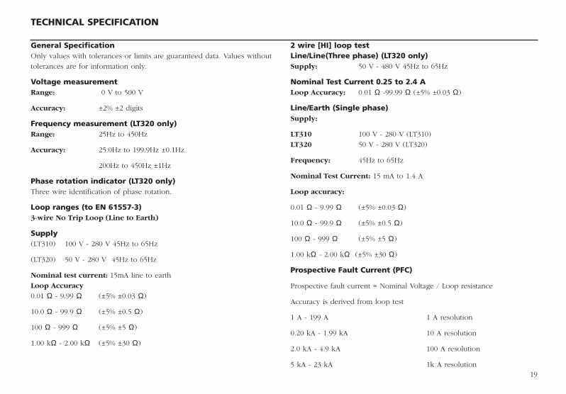
General SpecificationOnly values with tolerances or limits are guaranteed data. Values without
tolerances are for information only.
Voltage measurementRange: 0 V to 500 V
Accuracy: ±2% ±2 digits
Frequency measurement (LT320 only)Range: 25Hz to 450Hz
Accuracy: 25.0Hz to 199.9Hz ±0.1Hz
200Hz to 450Hz ±1Hz
Phase rotation indicator (LT320 only)Three wire identification of phase rotation.
Loop ranges (to EN 61557-3)3-wire No Trip Loop (Line to Earth)
Supply(LT310) 100 V - 280 V 45Hz to 65Hz
(LT320) 50 V - 280 V 45Hz to 65Hz
Nominal test current: 15mA line to earth
Loop Accuracy
0.01 Ω - 9.99 Ω (±5% ±0.03 Ω)
10.0 Ω - 99.9 Ω (±5% ±0.5 Ω)
100 Ω - 999 Ω (±5% ±5 Ω)
1.00 kΩ - 2.00 kΩ (±5% ±30 Ω)
2 wire [HI] loop testLine/Line(Three phase) (LT320 only)Supply: 50 V - 480 V 45Hz to 65Hz
Nominal Test Current 0.25 to 2.4 ALoop Accuracy: 0.01 Ω -99.99 Ω (±5% ±0.03 Ω)
Line/Earth (Single phase) Supply:
LT310 100 V - 280 V (LT310)
LT320 50 V - 280 V (LT320)
Frequency: 45Hz to 65Hz
Nominal Test Current: 15 mA to 1.4 A
Loop accuracy:
0.01 Ω - 9.99 Ω (±5% ±0.03 Ω)
10.0 Ω - 99.9 Ω (±5% ±0.5 Ω)
100 Ω - 999 Ω (±5% ±5 Ω)
1.00 kΩ - 2.00 kΩ (±5% ±30 Ω)
Prospective Fault Current (PFC)
Prospective fault current = Nominal Voltage / Loop resistance
Accuracy is derived from loop test
1 A - 199 A 1 A resolution
0.20 kA - 1.99 kA 10 A resolution
2.0 kA - 4.9 kA 100 A resolution
5 kA - 23 kA 1k A resolution19
LT300_UG_en_V01 07/05/2004 9:38 am Page 19

20
Temperature and humidityOperating Range: -5°C to +40°C
Operating Humidity: 93% R.H. at +40°C max.
Storage Range: -25°C to +70°C
Maximum altitude: 2000 m
Environmental Protection: Weather proof to IP54
SafetyMeets the requirements of EN61010-1 Cat III 300 V phase to earth.
IEC61557 Complies with the following parts of EN61557, Electrical safety in low
voltage systems up to 1000 V ac and 1500 V d.c.- Equipment for testing,
measuring or monitoring of protective measures:
Part1 - General Requirements
Part3 - Loop resistance
Power supply
Battery: 8 x 1.5 V cells IEC LR6 type(AA alkaline).
Rechargeable: NiCAD or NiMH cells may be used.
Battery condition is constantly shown on the display as a four-section bar
graph.
Battery Life: 2000 consecutive tests on any test using quality
batteries.
Weight
All units: 980gms
DimensionsAll units: 203 x 148 x 78 mm
E.M.CIn accordance with IEC61326 including amendment No.1
LT300_UG_en_V01 07/05/2004 9:38 am Page 20
21
BASIC AND SERVICE ERRORS ACCESSORIES AND EQUIPMENT
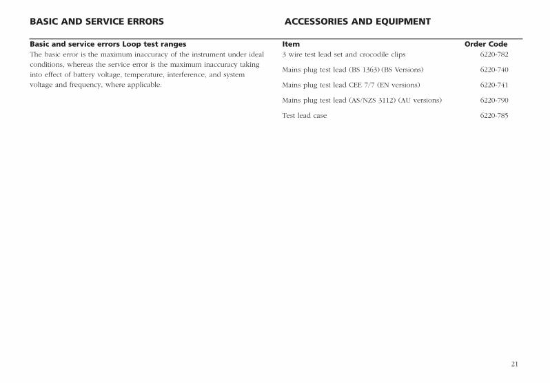
Basic and service errors Loop test rangesThe basic error is the maximum inaccuracy of the instrument under ideal
conditions, whereas the service error is the maximum inaccuracy taking
into effect of battery voltage, temperature, interference, and system
voltage and frequency, where applicable.
Item Order Code3 wire test lead set and crocodile clips 6220-782
Mains plug test lead (BS 1363) (BS Versions) 6220-740
Mains plug test lead CEE 7/7 (EN versions) 6220-741
Mains plug test lead (AS/NZS 3112) (AU versions) 6220-790
Test lead case 6220-785
LT300_UG_en_V01 07/05/2004 9:38 am Page 21

22
REPAIR AND WARRANTY
The instrument contains static sensitive devices, and care must be taken in
handling the printed circuit board. If an instrument’s protection has been
impaired it should not be used, but sent for repair by suitably trained and
qualified personnel. The protection is likely to be impaired if for example;
it shows visible damage; fails to perform the intended measurements; has
been subjected to prolonged storage under unfavourable conditions, or
has been subjected to severe transport stresses.
NEW INSTRUMENTS ARE GUARANTEED FOR 3 YEARS FROM THEDATE OF PURCHASE BY THE USER.
Note: Any unauthorized prior repair or adjustment will automatically
invalidate the Warranty.
INSTRUMENT REPAIR AND SPARE PARTSFor service requirements for Megger Instruments contact:
Megger Limited or Megger
Archcliffe Road Valley Forge Corporate Centre
Dover 2621 Van Buren Avenue
Kent CT17 9EN Norristown PA 19403
England. U.S.A.
Tel: +44 (0) 1304 502 243 Tel: +1 610 676 8579
Fax: +44 (0) 1304 207 342 Fax: +1 610 676 8625
or an approved repair company.
Returning and Instrument for RepairIf it necessary to retun an instrumnet for repair, a returns Authorisation
number must first be obtained by contacing one of the addresses shown.
You will be asked to provide key information, such as the instrument
serial number and fault reported when the number is issued. This will
enbable the Service Department to prepare in advance for the receipt of
your instrument, and to provide the best possible service to you.
The Returns Authorisation number should be clearly marked on the
outside of the product packaging, and on any related correspondence.
The instrument should be sent, freight paid to the appropriate address. If
appropriate a copy of the original purchase invoice and of the packing
note, should be sent simultaneously by airmail to expedite clearance
through customs.
For instruments requiring repair outside the warranty period a repair
estimate will be submitted to the sender, if required, before work on the
instrument commences.
Approved Repair CompaniesA number of independent instrument repair companies have been
authorised for repair work on most Megger instruments, using genuine
Megger spare parts. A list of approved companies is available from the UK
address shown on this page. Spare parts are also available.
LT300_UG_en_V01 07/05/2004 9:38 am Page 22

23
LT300_UG_en_V01 07/05/2004 9:38 am Page 23

M
Megger LimitedArchcliffe Road, DoverKent CT17 9EN England T +44 (0)1 304 502101 F +44 (0)1 304 207342
Megger 4271 Bronze Way, Dallas, Texas 75237-1019 USAT +1 800 723 2861 (USA ONLY)T +1 214 333 3201 F +1 214 331 7399
Megger Z.A. Du Buisson de la Couldre23 rue Eugène Henaff78190 TRAPPES FranceT +33 (0)1 30.16.08.90F +33 (0)1 34.61.23.77
OTHER TECHNICAL SALES OFFICESToronto CANADA, Sydney AUSTRALIA, Mumbai INDIA, Madrid SPAIN and the Kingdom of BAHRAIN.
Megger products are distributed in 146 countries worldwide.
This instrument is manufactured in the United Kingdom.The company reserves the right to change the specification or design without prior notice.
Megger is a registered trademark
Part No. 6172-xxx V01 Printed in England 0503www.megger.com
LT300_UG_en_V01 07/05/2004 9:38 am Page 24