Embed Size (px)
Citation preview

LTE-A Access, Core, and ProtocolArchitecture for D2D Communication
Dimitris Tsolkas, Eirini Liotou, Nikos Passas and Lazaros Merakos
1 Introduction to D2D Communications
The term device-to-device (D2D) communications refers to direct short-rangecommunications between terminals of a mobile network, without the intermediatetransmission to a base station (BS). Differing from conventional approaches, such asBluetooth and WiFi-Direct, D2D communications utilize licensed spectrum withquality of service (QoS) guarantees, while no manual network detection-selection isrequired. Compared to the very appealing cognitive radio communications, wheresecondary transmissions are allowed in parallel with cellular (primary) transmis-sions, D2D communications are established by cellular (primary) users, reaping thebenefits of being synchronized and controlled by the BS.
The introduction of D2D communications in cellular networks is expected to bebeneficial from a variety of perspectives, shifting the current cellular communi-cations to a more flexible and dynamic state. The short distance between D2Dtransmitter and receiver provides better link conditions and, thus, more efficientconnection with lower energy consumption. From the network’s perspective, theuse of spectrum and processing resources is reduced, since the intermediatetransmissions to the BS are avoided. Moreover, the coexistence of cellular andD2D transmissions in shared spectrum bands can lead to higher spectrum utili-zation, offloading at the same time the cellular network. From the operators’ point
D. Tsolkas (&) � E. Liotou � N. Passas � L. MerakosDepartment of Informatics and Telecommunications, University of Athens,15784 Athens, Greecee-mail: [email protected]
E. Liotoue-mail: [email protected]
N. Passase-mail: [email protected]
L. Merakose-mail: [email protected]
S. Mumtaz and J. Rodriguez (eds.), Smart Device to Smart DeviceCommunication, DOI: 10.1007/978-3-319-04963-2_2,� Springer International Publishing Switzerland 2014
23

of view, new business models, probably with a new charging policy, may bedesigned, without the need for purchasing additional spectrum.
In the standardization field, although direct communications are already offeredby local area networks in unlicensed ISM bands (e.g., WiFi-Direct), D2D com-munications are absent from most cellular systems. For the Long Term Evolution(LTE) system [1], the first standardization efforts have recently begun in Release12, in which D2D communications are mainly examined under the perspective ofproviding new commercial or public safety proximity services (ProSe) [2]. Inparallel, academia copes with a series of challenges toward enabling D2D com-munications (referred to as ProSe communications) in licensed spectrum.
The remainder of this chapter is organized as follows. First, we provide acomprehensive literature review on coexistence issues between D2D cellularcommunications. Next, we focus on D2D communication aspects currentlyexamined by 3GPP for integrating D2D communications in future LTE networks.Finally, we propose a scheme for enabling D2D communications in LTE-A net-works by enhancing standardized functionalities at the access network.
2 State of the Art on D2D Communications
In the literature, the coexistence of D2D and cellular communications is definedunder two basic spectrum sharing approaches: (i) the spectrum underlay, whereD2D transmissions reuse spectrum portions utilized by cellular transmitters and(ii) the spectrum overlay, where temporary empty spectrum portions are used. Acomparison of the two approaches can be found in [3] and [4], in terms oftransmission capacity and throughput, respectively. The key challenge in bothcases is the mitigation of the generated interferences. To this end, a widelyaccepted choice is the exploitation of the uplink (UL) cellular period, where theonly cellular interference victim is the immobile BS [5–7], shifting the majorinterference problem to the protection of the D2D receivers. However, the pro-tection of the D2D receivers is quite challenging, since in both underlay andoverlay approaches the interferences caused by neighboring transmissions (eithercellular or D2D) are far from negligible. This is an important concern, consideringthat the current trend is to reduce the cell size for achieving higher spatial networkcapacity. This trend poses the need for more research on controlling the inter-cellinterference perceived by D2D receivers in multicellular networks.
In the literature, the interference problem is mainly dealt with interference-aware Resource Allocation (RA) and Power Control (PC) schemes, e.g., [8–11].The BS selects appropriate spectrum resources and power levels for the D2Dtransmitters, taking into account information about the interferences among D2Dand cellular nodes. An important issue here is how the BS acquires the interferenceinformation. To this end, different mechanisms that inform the BS about thechannel conditions between the D2D nodes have been introduced, exploitingmainly periodic measurements guided by the BS, e.g., [9, 12, 13]. However,
24 D. Tsolkas et al.
gathering of the interference information consumes network resources, whilereliability highly correlates with the network traffic and topology changes. Addi-tionally, even if accurate information is available at the BS, the D2D RA and PCproblems are complex and hard to optimize. Consequently, the design of solutionsthat reduce the need for interference information at the BS is an open challenge.
Other approaches in the literature deal with the functional enhancementsrequired to cellular networks in order to enable D2D communications. Differentscenarios and challenges in an LTE network are presented in [14, 15]. Especiallyin [15], a detailed classification of D2D communication aspects in LTE networksis presented, and an abstract description of the signaling needed for D2D resourceallocations and data transmission is described. A major problem considered is thepeer discovery, i.e., the problem of finding whether the D2D peers are closeenough to directly communicate. The two basic peer discovery approaches are thecentralized and the distributed. The distributed approach is considered moreflexible and scalable, since it operates under local-level requirements and thecomplexity is shifted to the end-users. However, in modern cellular systems, suchas LTE, this approach can lead to uncontrolled use of the licensed band, imposingthe design of centrally controlled peer discovery schemes. A promising peer dis-covery solution has also been proposed by Qualcomm under the term FlashLinQ in[16]. In addition to peer discovery, this scheme includes: (i) timing and frequencysynchronization derived from cellular spectrum, (ii) link management, and (iii)channel-aware distributed power, data rate, and link scheduling.
Focusing on the LTE system, the integration of D2D communications isthoroughly examined in [17, 18], where the D2D connections are mainly used fornetwork performance optimization based on the idea of switching between thecellular and the D2D communication modes. This idea has also motivated anumber of other papers in the literature, e.g., [19–21]. The strong point of thisapproach is that the cellular communications take advantage of the D2D benefits,while the changes in the transmission mode are totally transparent to the end-user.By contrast, the requirement of avoiding interruption during switching from onemode to the other needs more investigation. Another promising approach,described in [22], proposes to enhance the LTE network entities in order to offerextra D2D communications on allocated or empty spectrum portions, indepen-dently of the cellular transmissions. The main advantage of this approach is thatthe network can handle both the types of communication separately, making D2Dconnections transparent to the core network. In both the approaches, the use oflicensed spectrum by the D2D transmitters calls for designing operator-controlledD2D schemes, and shifts the research interest to more centralized solutions.
Parallel to the research effort from academia, 3GPP has recently begun workingon integrating D2D communications in LTE Release 12. The main aspects con-sidered by 3GPP are provided in the following section.
LTE-A Access, Core, and Protocol Architecture for D2D Communication 25
3 D2D Communication Aspects in LTE-A Network
3.1 Background in LTE-A Network
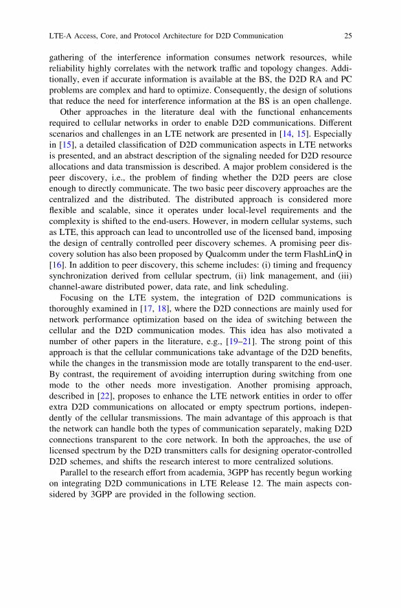
The main cellular system that is expected to adopt the D2D communications is theLTE system. The architecture of an LTE system (and the current release LTE-Advanced—LTE-A) is divided into two basic subsystems: the Evolved—Uni-versal Mobile Telecommunications System (UMTS) Terrestrial Radio AccessNetwork (E-UTRAN) and the Evolved Packet Core (EPC) (Fig. 1). This archi-tecture has been adopted on the Internet avoiding the hierarchical structures andproviding increased scalability and efficiency. On the one hand, the EPC subsys-tem is a flat all-IP system designed to support high packet data rates and lowlatency in serving flows. On the other hand the E-UTRAN is the access network ofthe LTE system. The main entities of E-UTRAN are the base stations—referred toas eNBs (evolved NodeBs) for the macro-cells and HeNBs (Home-eNBs) for thefemto-cells, and the cellular terminals—referred to as UEs (User Equipments).
The communication between eNBs and UEs is organized in frames of 10 ms,while each frame is divided into 10 subframes of 1 ms. Referring to transmissionsfrom and to eNBs, there are two basic categories of subframes; the downlink (DL)and the uplink (UL), respectively. In the frequency domain, each subframe utilizesscalable bandwidth up to 20 MHz (and up to 100 MHz through the carrieraggregation mechanism) divided into subcarriers of 15 KHz spacing. Subcarriersare organized into resource blocks RBs of 180 KHz each, i.e., 12 subcarriers definean RB, the minimum allocation unit in the network.
The introduction of the D2D communications must be done in respect to thisarchitecture, while the need for physical layer backward compatibility imposes theD2D-enabled UEs to utilize for their direct transmissions the current structure ofthe spectrum resources.
3.2 D2D Communication Scenarios
Currently, a lot of effort is being made by 3GPP Internet introducing the D2Dcommunications in the next amendments of the LTE system. For a better study ofthe problem 3GPP has adopted the following terminologies [2]:
ProSe direct communication: a communication between two or more UEs inproximity that are ProSe-enabled, by means of user plane transmission using E-UTRA technology via a path not traversing any network node.
ProSe-enabled UE: a UE that supports ProSe requirements and associatedprocedures. Unless explicitly stated otherwise, a ProSe-enabled UE refers both to anon-public safety UE and a public safety UE.
ProSe-enabled Public Safety UE: a ProSe-enabled UE that also supports ProSeprocedures and capabilities specific to Public Safety.
26 D. Tsolkas et al.

ProSe-enabled non-public safety UE: a UE that supports ProSe procedures andbut not capabilities specific to public safety.
ProSe direct discovery: a procedure employed by a ProSe-enabled UE to dis-cover other ProSe-enabled UEs in its vicinity by using only the capabilities of thetwo UEs with rel.12 E-UTRA technology.
EPC-level ProSe discovery: a process by which the EPC determines theproximity of two ProSe-enabled UEs and informs them of their proximity.
Based on this terminology two direct communication modes are proposed: (i)the network independent and (ii) the network authorized mode. The first mode ofoperation does not require any network assistance to authorize the connection andcommunication is performed by using only functionality and information availablelocally to the UE(s). This mode is applicable:
• only to preauthorized ProSe-enabled Public Safety UEs,• regardless of whether the UEs are served by E-UTRAN or not, and• to both one-to-one and one-to-many direct communication.
The second mode of operation for ProSe direct communication always requiresnetwork assistance by the EPC to authorize the connection. This mode of operationapplies:
• to ProSe one-to-one direct communication,• when both UEs are ‘‘served by E-UTRAN,’’ and• for Public Safety UEs it may apply when only one UE is served by E-UTRAN.
For these communication modes and considering the registered public landmobile network (PLMN), the direct communication path and coverage status (incoverage or out of coverage), a number of different possible communicationscenarios are defined as shown in Table 1, while a comprehensive illustration ofthese scenarios is provided in Fig. 2. However, these scenarios do not cover all thepossible scenarios for direct communication, and 3GPP in working on adding morescenarios especially for the case of group communication.
UELTE-Uu
E-UTRAN
UE
EPC
S1
LTE-Uu
Fig. 1 LTE-A architecture
LTE-A Access, Core, and Protocol Architecture for D2D Communication 27

3.3 D2D Reference Architecture
For supporting the scenarios defined above enhancements are required to the LTEarchitecture. Figure 3 depicts this architecture and aims to fulfill the followingrequirements posed by 3GPP.
• Enable the operator to control the ProSe discovery feature in its network andauthorize the functionality required for the ProSe discovery functions for eachUE.
• Enable the ProSe communication or ProSe-assisted WLAN Direct communi-cation and seamless service continuity when switching user traffic between aninfrastructure paths and a ProSe communication path of the ProSe-enabled UEs.
• Enable HPLMN operator to authorize ProSe-enabled UE to use ProSe com-munication separately for the HPLMN and for roaming in VPLMNs.
• Enable an authorized third party ProSe application to interact with 3GPP net-work in order to utilize the ProSe services offered by the network.
• Be able to control ProSe communication between ProSe-enabled UEs when theUEs are served by a same eNB or different eNBs.
• Accommodate the ProSe-related security functions related to privacy, supportfor regulatory functions including Lawful Interception, and authentication uponProSe discovery and ProSe communication.
• Enable the operator to authorize and authenticate the third-party applicationsbefore making use of the ProSe feature.
• Accommodate for charging by the operators (HPLMN or VPLMN) for utili-zation of the ProSe functionality.
As depicted in Fig. 3, additional to the entities of the conventional LTEarchitecture, a number of new entities are required as shown in Fig. 1. Theseentities are as follows:
Table 1 D2D communication scenarios in LTE networks
Scenario In/out coverage Serving PLMN/cell
UE-A UE-B
A Out Out No serving PLMN/cellB In Out No serving PLMN/cell for UE-BC In In Same PLMN/cellD In In Same PLMN—different cellE In In Different PLMN/cell
both UEs are in both cells’ coverageF In In Different PLMN/cell
UE-A is in both cells’ coverageUE-B is in serving cell’s coverage
G In In Different PLMN/cellboth UEs are in their own serving cells’ coverage)
28 D. Tsolkas et al.

Application servers (ProSe App Server) incorporates the ProSe capability forbuilding the application functionality, e.g., in the Public Safety cases they can bespecific agencies (PSAP) or in the commercial cases social media. These appli-cations are defined outside the 3GPP architecture but there may be reference pointstoward 3GPP entities. The Application server can communicate toward an appli-cation in the UE.
Applications in the UE (ProSe UEs App) use the ProSe capability for buildingthe application functionality. An example may be for communication betweenmembers of Public Safety groups or for social media application that requests tofind buddies in proximity.
ProSe Function in the network (as part of EPS) defined by 3GPP has a refer-ence point toward the ProSe App Server, the EPC, and the UE. The functionality
PLMN A (a)
PLMN A PLMN A
(b)
UE2UE1
PLMN A (c) (d)
PLMN A PLMN B(f)
UE1PLMN A
UE1 UE2
UE1
UE2
UE1
UE2
UE2PLMN B
PLMN A PLMN B
(e)
UE1PLMN A
UE2PLMN B
PLMN A PLMN B(g)
UE1PLMN A
UE2PLMN B
Fig. 2 3GPP direct communication scenarios [2]
LTE-A Access, Core, and Protocol Architecture for D2D Communication 29
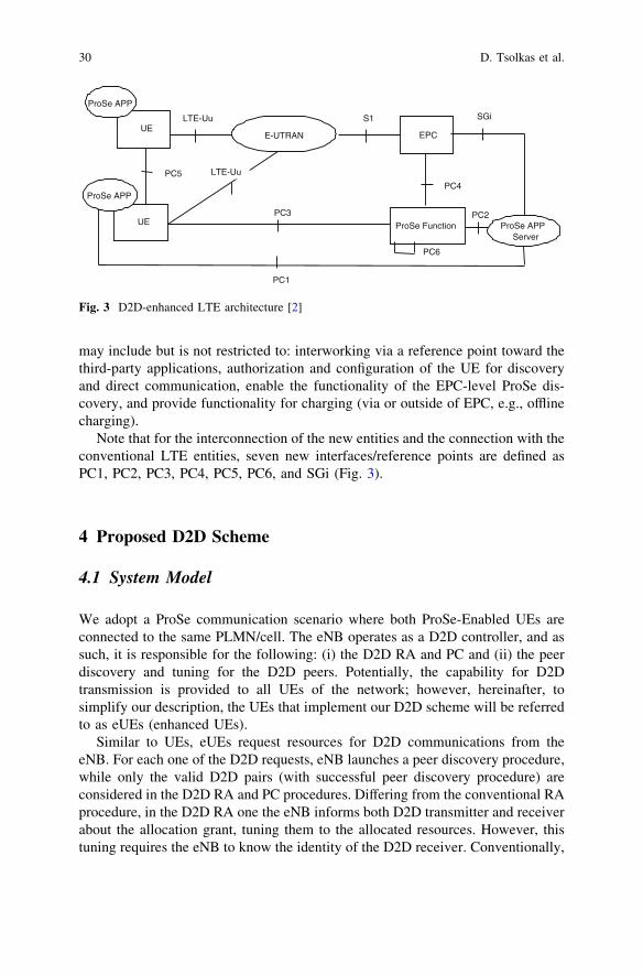
may include but is not restricted to: interworking via a reference point toward thethird-party applications, authorization and configuration of the UE for discoveryand direct communication, enable the functionality of the EPC-level ProSe dis-covery, and provide functionality for charging (via or outside of EPC, e.g., offlinecharging).
Note that for the interconnection of the new entities and the connection with theconventional LTE entities, seven new interfaces/reference points are defined asPC1, PC2, PC3, PC4, PC5, PC6, and SGi (Fig. 3).
4 Proposed D2D Scheme
4.1 System Model
We adopt a ProSe communication scenario where both ProSe-Enabled UEs areconnected to the same PLMN/cell. The eNB operates as a D2D controller, and assuch, it is responsible for the following: (i) the D2D RA and PC and (ii) the peerdiscovery and tuning for the D2D peers. Potentially, the capability for D2Dtransmission is provided to all UEs of the network; however, hereinafter, tosimplify our description, the UEs that implement our D2D scheme will be referredto as eUEs (enhanced UEs).
Similar to UEs, eUEs request resources for D2D communications from theeNB. For each one of the D2D requests, eNB launches a peer discovery procedure,while only the valid D2D pairs (with successful peer discovery procedure) areconsidered in the D2D RA and PC procedures. Differing from the conventional RAprocedure, in the D2D RA one the eNB informs both D2D transmitter and receiverabout the allocation grant, tuning them to the allocated resources. However, thistuning requires the eNB to know the identity of the D2D receiver. Conventionally,
UE
ProSe APP
LTE-Uu
E-UTRAN
UE
ProSe APP
EPC
S1
ProSe APP Server
SGi
ProSe Function
PC4
PC2
PC5 LTE-Uu
PC3
PC1
PC6
Fig. 3 D2D-enhanced LTE architecture [2]
30 D. Tsolkas et al.

identities, such as the destination IP addresses, or destination IMSI/S-TMSIidentities (International-/Subscriber-Temporary Mobile Subscriber Identity), orother upper explicit level identities (e.g., SIP addresses), are not available locallyat the eNB and thus, cannot be used without the involvement of the core network.Thus, the introduction of a new identity for each eUE is required. As explainedlater, this new identity is generated by each eUE during its initial access to thenetwork, and any transmitting eUE device has the ability to produce the D2Didentity of its target eUE. When an eUE wants to establish a D2D connection, theD2D identity of the target eUE is included in the D2D resource request. Theserving eNB, having a one-to-one mapping between standardized and D2Didentities, uses the former identities in order to inform both D2D transmitter andreceiver about the resource allocation.
The adopted D2D model can be summarized as follows:
• Each eUE produces its D2D identity and transmits it to the eNB during its firstaccess to the network.
• eUEs make D2D spectrum requests using the standard spectrum request pro-cedure, including, however, the D2D identity of the target D2D receiver.
• The eNB launches a peer discovery procedure for the requested D2D pair.• The eNB allocates cellular resources to valid D2D pairs and informs both D2D
peers, tuning them indirectly at the same spectrum portion. The D2D RAcombined with a PC scheme guarantees the interference-free conditions betweencellular and D2D system.
• The eUE transmitter sends its data using the spectrum region that has beenallocated by the eNB, while the eUE receiver tunes to the same spectrum regionto receive the transmitted data.
• The eUE receiver acknowledges the reception (or not) of the data through theeNB following the conventional-standardized procedure.
The proposed system model requires enhanced functionality only at the accessnetwork, i.e., at the standard UEs (upgrading them to eUEs), and at the eNBs.
4.2 Proposed Enhancements in Access Network
4.2.1 D2D Identity Production and Notification at the eNB
In standardized–cellular communications, the eNB uses the Cell Radio NetworkTemporary Identifier (C-RNTI) to uniquely identify UEs. A unique C-RNTI isassigned by the eNB to a UE during the initial random access procedure and isused for identifying the Radio Resource Control (RRC) connection and forscheduling purposes. Practically, the coding/decoding of the physical downlinkcontrol channel (PDCCH) intended for a specific UE is based on this UE’s C-RNTI [1]. In more detail, each UE initiates a contention-based access to thenetwork by transmitting a preamble sequence on the physical random access
LTE-A Access, Core, and Protocol Architecture for D2D Communication 31

channel (PRACH) (Fig. 4). As a result, it is supplied with a temporary random C-RNTI by the eNB via the random access response message. Assuming that con-tention resolution due to potential preamble collisions is not required or is alreadyresolved, this temporary C-RNTI will be promoted to normal C-RNTI, to be usedfor unique identification inside the cell, for as long as this UE stays in connectedmode. The random access procedure is successfully completed upon the receptionand acknowledgment of the RRC Connection Setup message by the UE.
In D2D communications, as resulted by the description of the proposed systemmodel in Sect. 2, an additional D2D identity is required at the eNB for the D2Dtransmission. Hereafter, this identity will be referred to as D2D-ID. The eUEregister to the network like any standard UE following the procedure describedabove, including, however, its D2D-ID in the RRC Connection Request message,transmitted via the physical UL shared channel (PUSCH). This is the same mes-sage where the initial UE identity (International-/Temporary Mobile SubscriberIdentity—IMSI/S-TMSI) is included. The D2D-ID is introduced as a new infor-mation element in the RRC connection request message (Fig. 4) [23]. In line withthe 3GPP description of the RRC connection request, we define the D2D-ID as anoptional (OP) information element, in the sense that its presence or absence issignificant and modifies the behavior of the receiver. Nevertheless, whether theinformation is present or not does not lead to an error diagnosis [23].
The D2D-ID is produced by the eUE, using a transformation of the MobileSubscriber Identification Number (MSIN), the 10-digit number that uniquely andglobally identifies a mobile phone. All eUEs use the same algorithm/technique forthe D2D-ID production; thus, provided that the MSIN of the target eUE is knownat the eUE transmitter (in its contact list), the target’s D2D-ID can be faultlesslyproduced. Note that in the general/simplest approach the D2D-ID could be theMSIN. However, the adoption of this new D2D-ID, instead of directly using theMSIN, is based on privacy, security, and optimization reasons. The transformationalgorithm can guarantee the concealment of the MSIN and also the production ofD2D-IDs from valid-MSIN, preventing users to use any 10-digit number whentrying to establish a D2D connection. The selection of an efficient algorithm for theMSIN transformation is out of the scope of this paper. However, any conventionalhashing algorithm is applicable.
4.2.2 D2D Connection Request
Let eUE1 want to establish a D2D connection to eUE2. Assume that both eUEshave already submitted their D2D-IDs using the D2D-ID information element intheir RRC connection request message, as explained above. Normally, when a UEhas data to transmit, the Buffer Status Report (BSR) procedure is initiated [23].According to this procedure, a Regular BSR informs the serving eNB via thePUSCH about the amount of data pending for transmission in its UL buffers. Notethat, if no BSR is already allocated (i.e., no other transmissions are already
32 D. Tsolkas et al.

initiated), a single-bit Scheduling Request (SR) on the physical UL control channel(PUCCH) precedes the BSR request [23].
In addition to the standard information that any UE includes in the BSR request,the eUE1 produces the D2D-ID of the target UE (eUE2) and adds it to the request(Fig. 4). An unused 16-bit long MAC Control Element inside the BSR request isused for that purpose, differentiating a D2D request from a cellular one. Thiselement utilizes space currently reserved for future use and it is indexed in theMAC Protocol Data Unit (PDU) sub-header by the Logical Channel ID (LCID)value equal to 11,000. The new element is called D2D Receiver ID and isappended to the existing LCID values, such as the common control channel(CCCH), the C-RNTI, and the Padding [23]. The MAC PDU structure thatincludes D2D requests is shown in Fig. 5. In this figure, the extra MAC sub-headerfor D2D request is depicted as the last sub-header of the MAC header.
The eNB keeps a one-to-one mapping between C-RNTIs and D2D-IDs, createdduring the initial network access of each eUE, as previously explained. Conse-quently, upon the reception of a request, eNB locates the C-RNTIs of therequesting and the destination eUE in this mapping table using the respective
eUE 1 eNB eUE 2
PRACH: RA Preamble
PUSCH: RRC Connection Request
PDSCH: RA Response
PDSCH: RRC Connection Setup
Initial network access: D2D on
New data for transmission to eUE 2
PUCCH (SR)
PUSCH (BSR)
PDCCH (UL grant for BSR)
Resource Allocation (for cellular & D2D)
PUSCH (data transmission)
PUCCH (ACK/NACK)
Registered to network: D2D on
Contains the D2D-ID of eUE 1
Contains the D2D-ID of the target eUE 2
Decoded with C-RNTI 2
Decoded with C-RNTI 1
Assigns C-RNTI 1
PUSCH: RRC Connection Setup Complete
Assuming no random access
contention
PDCCH (D2D RX grant)PDCCH (D2D TX grant)
PHICH(ACK/NACK)
Fig. 4 D2D enhancements in standard LTE signaling
LTE-A Access, Core, and Protocol Architecture for D2D Communication 33

D2D-IDs. Following that, it uses the corresponding C-RNTIs to encode the allo-cation messages (allocation grant) for the eUE transmitter and receiver.
4.2.3 D2D Resource Allocation and Power Control
The selection of the D2D RA and PC is a key factor for guaranteeing fair, reliable,and interference-free spectrum sharing between cellular and D2D communica-tions, as well as among D2D communications. The secondary resource allocationscheme can be independent of the cellular/primary one. However, as shown in[13], the primary resource allocation algorithm includes important information thatcan be used for the design of an interference-aware secondary allocator. In thegeneral case, eNB can use any RA and PC scheme that guarantees interference-free conditions among all the concurrent transmissions.
Differing from the standardized procedure, the D2D allocation grant is alsotransmitted to the target eUEs (D2D receivers) to inform them about the appro-priate spectrum region in which they will receive the D2D data. Potentially, thischoice increases the loading on downing control channels; however, no changes inthe eNB signaling are needed. Note that in Fig. 4, we refer to the resource allo-cation to the D2D receiver as D2D RX grant to differentiate it from the D2D TXgrant of the D2D transmitter, even though both refer to the same physicalresources.
The very first D2D RA to a D2D request is used for device discovery purposes.The eNB allocates an empty RB to the D2D request as if the request was by acellular UE. This RB is used by the D2D transmitter to send a pilot signal towardchecking if it can reach the D2D receiver. Since the RB is more than adequate for apilot signal, the D2D transmitter adds data to fill in the resources of the RB,utilizing in that way the extra spectrum space in case the D2D receiver is reached.Note that the appropriate power for the pilot signal transmission is fixed anddepends on the range of the D2D connections that the eNB allows inside its cell.After a successful peer discovery, the D2D receiver acknowledges the reception ofthe pilot signal to eNB. For the subsequent allocations of the same request, the
Header Payload (SDU)
Sub-header 1
Sub-header K
MAC Ctrl Element 1
MAC Ctrl Element N
R ER LCID = 11000 D2D Receiver ID
MAC PDU
Ctrl Elements Padding
Sub-header 2
MAC Ctrl Element 2
Fig. 5 Enhanced MAC PDU
34 D. Tsolkas et al.

eNB can utilize primarily allocated or empty resources referring to the spectrumunderlay and overlay approach, respectively.
For the D2D transmissions the ACK/NACK messages are transmitted as in thecase of standardized–cellular transmissions. According to the standardized pro-cedures, an ACK/NACK message is transmitted by the receiver to eNB throughthe PUCCH in order to acknowledge (or not) whether the data have been suc-cessfully received. Then, eNB forwards this message through the Physical HybridARQ Indicator Channel (PHICH) [23] to inform the transmitter.
4.3 Evaluation Results
To evaluate the proposed scheme, we made changes to the system level simulatorproposed in [24] in order to support D2D communications. The basic parametersof the simulation are shown in Table 2.
4.3.1 D2D Spatial Spectrum Reuse
In Fig. 6, we examine the maximum number of D2D devices that can transmitconcurrently with a UE transmitter located at a distance of half the cell radius fromthe eNB. The UE, through the power control procedure, transmits with the min-imum power that guarantees a target SINR threshold at the eNB. D2D transmittersuse fixed power that equals to -19 dBm, a power level that can guarantee anacceptable SINR level at a small distance (up to 50 m). As it was expected themore the D2D transmitters the more the SINR degradation at the eNB. However,an interesting result extracted by Fig. 6, is that for D2D users located at a distancemore than *35 % of the cell radius from the eNB, the SINR distortion is negli-gible and practically independent of the number of D2D transmitters. This resultvalidates that the D2D connectivity is a suitable candidate for improving thespatial spectrum utilization, especially at areas closer to cell edges. Fromthe opposite perspective, the protection of the D2D connections from the UE andthe other D2D transmissions is also very important. In this direction, a compre-hensive result is given in Fig. 7.
In Fig. 7, we calculate the percentage of the cell area where potential D2Dreceivers are instantaneously not interfered by the cellular UE’s transmission. Thispercentage is actually a measure of the maximum spatial spectrum reuse ratio. Asshown in this figure, the dependency of the spectrum reusability on the distance ofthe cellular UE from the eNB is higher as the target SINR at the eNB increases.The higher the required quality for a cellular communication, the higher therequired SINR at the eNB, and, thus, the higher the transmit power of the UE,something that will inevitably reduce the allowed D2D reuse. Moreover, since theUE transmitter uses an omnidirectional antenna, its signal best covers the cell areawhen it is located at a distance of approximately half the radius from the eNB,
LTE-A Access, Core, and Protocol Architecture for D2D Communication 35

suppressing the possibility for parallel noninterfering D2D transmissions, whichjustifies the concave shape of the curves. In the case of multiple D2D transmittersreusing the same resources, this ratio is expected to decrease, because neighboringD2D transmissions will cause interference to each other. Generally, during eachUL cellular transmission, around 40–100 % of the cell area seems to be availablefor extra D2D transmissions.
4.3.2 Performance Degradation due to Device Discovery Procedure
In Fig. 8, we monitor the system’s performance in terms of throughput for 500subframes in two cases: (i) the conventional one, with no device discovery (solid
Table 2 Basic simulationparameters
Parameter Value
Region of interest (ROI) Cell sectorCell radius 320 m(e) UE distribution UniformCarrier frequency 2 GHzBandwidth 10 MHzPathloss model 3GPP TS 36.942Max cellular UE Tx power 200 mW (23 dBm)Fixed D2D UE (eUE) Tx power 0.0125 mW (-19 dBm)eNB noise figure 5 dBeNB thermal noise density -174 dBm/HzAccepted block error rate (BLER) \10 %
Fig. 6 SINR at eNB for different number and locations of D2D transmitters
36 D. Tsolkas et al.

line), and (ii) the case that 20 % of the UEs in a target cell launch a devicediscovery scheme (dashed line). We assume that a single RB is allocated for eachexpression code transmission, while the throughput is calculated in a frame perframe basis (every 10 subframes). The result depicted in Fig. 8 shows a reasonabledecrease in the achievable throughput of about 13 %. However, in this result, thegain on better spectrum utilization offered by the direct communications is notincluded.
Fig. 7 Spatial spectrum reuse ratio in a cell for different UE locations
Fig. 8 Burdening of cellular communication’s throughput due to discovery transmissions
LTE-A Access, Core, and Protocol Architecture for D2D Communication 37

4.3.3 Traffic Offloading due to Direct Transmissions
After a successful device discovery procedure, intra-cell communications, i.e.,cellular communications between UEs served by the same eNB, can switch todirect mode. This results to better spectrum utilization due to the proximity gain,and consequently, higher total data rates are offered to the system. Figure 9 depictsthe mean data rate offered to conventional transmissions with (solid line) andwithout (dashed line) the ability of switching the valid intra-cell communicationsto direct ones. Two different scenarios are assumed. In the first scenario, the intra-cell communication requests are 20 % of the total requests (blue curves), while inthe second one, they are increased to 40 % (red curves). As shown in Fig. 9, in thesecond scenario, the extra mean data rate offered to an inter-cell communication ishigher than that in the first one, due to the increased number of transmissionsserved in direct mode. Also, for both scenarios, the offered gain in data rates isquite large (up to 50 %) and decreases for an increased number of UEs. Thisdecrease is because the spectrum resources are limited, and as the number of UEsincreases, the available spectrum utilization for every UE is reduced.
References
1. 3GPP TS 36.300, v9.9.0, Rel.9, in Evolved Universal Terrestrial Radio Access (E-UTRA) andEvolved Universal Terrestrial Radio Access Network (E-UTRAN), overall description, Jan2013
2. 3GPP TR 23.703 v0.5, Rel 12, in Technical Specification Group Services and SystemAspects; Study on architecture enhancements to support Proximity Services (ProSe), June2013
Fig. 9 Offered data rates with enabled and disabled direct communications
38 D. Tsolkas et al.

3. K. Huang, V.K.N. Lau, Y. Chen, Spectrum sharing between cellular and mobile ad hocnetworks: transmission-capacity trade-off. IEEE J. Sel. Areas Commun. 27(7), 1256–1267(2009)
4. C.H. Yu, K. Doppler, C.B. Ribeiro, O. Tirkkonen, resource sharing optimization for device-to-device communication underlaying cellular networks. IEEE Trans. Wirel. Commun. 10(8),2752–2763 (2011)
5. H. Min, J. Lee, S. Park, D. Hong, Capacity enhancement using an interference limited areafor device-to-device uplink underlaying cellular networks. IEEE Trans. Wirel. Commun.10(12), 3995–4000 (2011)
6. H. Min, W. Seo, J. Lee, S. Park, D. Hong, Reliability improvement using receive modeselection in the device-to-device uplink period underlaying cellular networks. IEEE Trans.Wirel. Commun. 10(2), 413–418 (2011)
7. B. Kaufman, J. Lilleberg, B. Aazhang, Spectrum sharing scheme between cellular users andad-hoc device-to-device users. IEEE Trans. Wirel. Commun. 12(3), 1038–1049 (2013)
8. P. Janis, V. Koivunen, C. Ribeiro, J. Korhonen, K. Doppler, K. Hugl, Interference-awareresource allocation for device-to-device radio underlaying cellular networks. in IEEE 69thVehicular Technology Conference (VTC Spring 2009), pp. 1–5, 26–29 April 2009
9. C. Xu, L. Song, Z. Han, Q. Zhao, X. Wang, B. Jiao, Interference-aware resource allocationfor device-to-device communications as an underlay using sequential second price auction. inIEEE International Conference on Communications (ICC), pp. 445–449, 10–15 June 2012
10. C.H. Yu, O. Tirkkonen, K. Doppler, C. Ribeiro, Power optimization of device-to-devicecommunication underlaying cellular communication. in IEEE International Conference onCommunications (ICC ‘09), pp. 1–5, 14–18 June 2009
11. X. Xiao, X. Tao, J. Lu, A QoS-aware power optimization scheme in ofdma systems withintegrated device-to-device (D2D) communications. IEEE Vehicular Technology Conference(VTC Fall), pp. 1–5, 5–8 Sept 2011
12. P. Jänis, C. Yu, K. Doppler, C. Ribeiro, C. Wijting, K. Hugl, O. Tirkkonen, V. Koivunen,Device-to-device communication underlaying cellular communications systems, Int’l J.Commun. Netw. Sys. Sci. 2(3), 169–178 (2009)
13. D. Tsolkas, E. Liotou, N. Passas, L. Merakos, A graph-coloring secondary resource allocationfor D2D communications in LTE networks. in The 17th IEEE International Workshop onComputer-Aided Modeling Analysis and Design of Communication Links and Networks(IEEE CAMAD 2012), Barcelona, Spain, Sept 2012
14. G. Fodor, E. Dahlman, G. Mildh, S. Parkvall, N. Reider, G. Miklós, Z. Turányi, Designaspects of network assisted device-to-device communications. IEEE Commun. Mag. 50(3),170–177 (2012)
15. L. Lei, Z. Zhong, C. Lin, X. Shen, Operator controlled device-to-device communications inLTE-advanced networks. IEEE Wirel. Commun. 19(3), 96–104 (2012)
16. M.S. Corson, R. Laroia, J. Li, V. Park, T. Richardson, G. Tsirtsis, Toward proximity-awareinternetworking. IEEE Wirel. Commun. 17(6), 26–33 (2010)
17. M.J. Yang, S.Y. Lim, H.J. Park, N.H. Park, Solving the data overload: Device-to-devicebearer control architecture for cellular data offloading. IEEE Veh. Technol. Mag. 8(1), 31–39(2013)
18. K. Doppler, M. Rinne, C. Wijting, C. Ribeiro, K. Hugl, Device-to-device communication asan underlay to LTE-Advanced networks, IEEE Commun. Mag. 47(12), 42–49 (2009)
19. J. Li, J.B. Song, Z. Han, Network connectivity optimization for device-to-device wirelesssystem with femtocells, IEEE Trans. Veh. Technol. 62(7), 3098–3109 (2013)
20. M. Belleschi, G. Fodor, A. Abrardo, Performance analysis of a distributed resource allocationscheme for D2D communications. in IEEE GLOBECOM Workshops 2011 (GC Wkshps),pp. 358–362, 5–9 Dec 2011
21. M. Jung, K. Hwang, S. Choi, Joint mode selection and power allocation scheme for power-efficient device-to-device (D2D) communication. in IEEE 75th Vehicular TechnologyConference (VTC Spring 2012), pp. 1–5, 6–9 May 2012
LTE-A Access, Core, and Protocol Architecture for D2D Communication 39

22. D. Tsolkas, E. Liotou, N. Passas, L. Merakos, Enabling D2D communications in LTEnetworks. in IEEE International Symposium on Personal, Indoor and Mobile RadioCommunications (PIMRC) 2013, London, United Kingdom, Sept 2013
23. 3GPP TS36.321 v9.6.0, Rel.9, Evolved Universal Terrestrial Radio Access (E-UTRA),Medium Access Control (MAC) protocol specification, March 2012
24. J.C. Ikuno, M. Wrulich, M. Rupp, System level simulation of LTE networks. in Proceedingsof 2010 IEEE 71st Vehicular Technology Conference, Taipei, Taiwan, May 2010. Availableat http://publik.tuwien.ac.at/files/PubDat_184908.pdf
40 D. Tsolkas et al.

http://www.springer.com/978-3-319-04962-5
![Benchmarking Practical RRM Algorithms for D2D Communications in LTE Advanced · 2018-06-08 · arXiv:1306.5305v1 [cs.IT] 22 Jun 2013 Benchmarking Practical RRM Algorithms for D2D](https://img.pdfslide.net/doc/110x75/5e5574dc600940241e3842fb/benchmarking-practical-rrm-algorithms-for-d2d-communications-in-lte-advanced-2018-06-08.jpg)