Embed Size (px)
Citation preview

hf-praxis 7/2016 61
LTE
Analog integration plays an important
role in addressing new challenges faced by
LTE-Advanced radio engineers. The 3rd
Generation Partnership Project (3GPP) is
working on Release 12 (Rel-12) of the LTE-Advanced standard.
3GPP Rel-12 includes many enhancements to 4G radio access technology including wideband carrier aggregation, multi-layer spatial multiplexing and advan-ced antenna configurations. The Rel-12 enhancements will chal-lenge radio designers to integrate more RF transmitter channels that will enable smaller, lower power and higher performance eNodeB base stations. Advance-ments in RF analog integration and disruptive radio architec-tures can help engineers success-fully overcome the integration challenge. This two-part application note series reviews new develop-
ments in the Fourth Generation Long Term Evolution (4G-LTE) cellular standard. The applica-tion note series explores LTE-Advanced (LTE-A) Release-12 (Rel-12) features and the impact on eNodeB radio frequency (RF) transmitters. The application notes reveal how analog integration can overcome
design challenges arising from the latest 4G developments. Part 1, this application note, exa-mines market forces driving glo-bal adoption of the LTE standard and trends in 4G radio access technology. Readers will learn about work items outlined in the 3rd Generation Partnership Project (3GPP) Rel-12 specifi-
cation. Topics include carrier aggregation (CA), spatial mul-tiplexing, and active antenna systems (AAS). Part 2 of this series will explore the analog integration challen-ges in 4G base stations. Rel-12 features such as wideband down-link carrier aggregation, down-link multiple-input multiple-out
LTE-A Rel-12 shapes new eNodeB Transmitter Architecture
Damian Anzaldo, Principal Member of Technical Staff - Field Applications, Maxim
Integrated
Figure 1. LTE release timeline showing evolutionary advancements in radio access technology
Figure 2. The features and benefits of Release 12 work items
Part 1: Technology Evolution

62 hf-praxis 7/2016
RF & Wireless
(MIMO) spatial multiplexing, and AAS with embedded RF, present new design challenges in next-generation eNodeB radios. A disruptive bits-to-RF solution is introduced that can help engi-neers shape alternative radio transmitter architectures. The discussion focuses on novel RF digital-to-analog converter (RF- DAC) technology that yields a single-chip, wideband RF trans-mitter solution. Readers will learn about system-level appli-cations of the RF-DAC and the integration benefits that it deli-vers to eNodeB radio design.
OverviewLong-Term Evolution (LTE) is recognized as the fastest grow-ing mobile broadband techno-logy, and becoming the most
widely adopted cellular standard worldwide. LTE‘s global rate of adoption by wireless service providers has exceeded prior second- generation (2G) and third-generation (3G) deploy-ments. The popularity of LTE is mainly due to its high spectral efficiency and high peak data rates, low-latency IP-based net-work, and evolutionary roadmap.
For consumers, this translates to reliable high- speed mobile access and anywhere-anytime connectivity. For wireless ser-vice providers, LTE offers effi-cient spectrum utilization, net-work capacity gains and signifi-cant improvements in total cost of ownership (TCO). But LTE is not „true 4G“ service and is technically still considered 3.9G.
The true fourth-generation (4G) radio communication standard, known as International Mobile Telecommunications-Advanced (IMT-Advanced), must meet the requirements set forth by the In-ternational Telecommunication Union Radio Sector (ITU-R). IMT-Advanced defines 4G as a service that delivers 100Mbps peak data rates to high-mobi-lity users, and 1Gbps peak data rates for low-mobility clients. To comply with the IMT-Advanced vision, the 3GPP has develo-ped many enhancements since the initial LTE Rel-8 standard published in 2008.
In Rel-10 the 3GPP introduced LTE-Advanced as „true 4G“ ser-vice to meet or exceed the IMT-Advanced requirements. LTE-A Rel-10 was the next step in the
mobile broadband evolution and further expanded on LTE‘s basic feature set. Presently, Rel-12 is close to introduction with a functional freeze date planned for March 2015. Rel-12 will include evolutionary enhance-ments across radio access tech-nology. Figure 1 illustrates LTE development timelines where it can be seen that theoretical peak downlink (DL) and uplink (UL) data rates have increased about 10x and 20x, respectively, from DL = 300 Mbps/UL = 75 Mbps in Rel-8 to DL = 3Gbps/UL = 1.5Gbps in Rel-10. The extra-ordinary increase in peak data rates is due in part to wideband CA, complimented by multilayer spatial multiplexing introduced in Rel-10 and now an important part of Rel-12 enhancements.
LTE-A Rel-12 and the Impact on eNodeB Radios
Rel-12 enhancements will signi-ficantly impact how evolved NodeB (eNodeB) radios are designed. Some of the impor-tant Rel-12 items include new combinations of carrier aggrega-tion, spatial multiplexing enhan-cements with downlink MIMO, and RF requirements needed in AAS. Figure 2 summarizes some of the Rel-12 items with respec-tive features and benefits. A clo-ser look at the Rel-12 features
Figure 3. When mobile users connect with more data-intensive devices, as in the U.S. LTE market, the decline in revenue-per- connection is muted and operators generate higher ARPU. Source of image is GSMA Wireless Intelligence.www.gsma.com/
Figure 4. To sustain data growth, the operator CAPEX investment in mobile networks is forecast to exceed $1.7 trillion (USD) from 2012 to 2020. Source of image is GSMA Wireless Intelligence
Figure 5. Four primary market forces are driving evolutionary improvements in radio access technology

hf-praxis 7/2016 63
RF & Wireless
reveals how the LTE mobile broadband network is evolving to realize improvements in capa-city, spectrum utilization, peak data rates, and coverage.
Carrier aggregation allows ope-rators to deliver higher peak data rates (bits/sec) and bet-ter manage fragmented radio spectrum spanning 700MHz to 3.5GHz. Adopting spatial mul-tiplexing with 8x8 MIMO incre-ases spectral efficiency (bits/sec/Hz) to serve users with higher
peak data rates while maximi-zing limited and valuable spec-trum resources.
Migration to AAS enables macro-cell base stations to implement beamforming tech-niques that will improve cell-edge and sector capacity while reducing power consumption. The Rel-12 feature enhance-ments bring many benefits to the LTE ecosystem, along with new radio design and radio architec-ture challenges.
Downlink carrier aggregation (DL-CA) means that base-sta-tion radio transmitters must support ultra-wide bandwidths with carrier frequency agility, and 8x8 MIMO requires more RF transmitter channels. AAS with embedded RF dedicates a radio transceiver for each antenna element with up to 16 antenna elements. This signifi-cantly increases radio channel density. In macro cell base- sta-tion applications the DL-CA, MIMO, and AAS features drive
a need for compact, low-power, high-dynamic-performance radio solutions. Bound by a triad constraint of form-factor size, power consumption, and system cost, the effect of Rel-12 enhancements is profound. RF engineer‘s face new eNo-deB design challenges: integrate more radio channels in a smaller footprint and operate at lower power with better dynamic per-formance, all without increasing system cost. To help engineers overcome these challenges, RF analog integration and disrup-tive radio architectures offer a solution that can reshape eNo-deB transmitter design.
Before addressing the details of Rel-12 features, it is important to understand the market drivers and why LTE-A Rel-12 is being drafted. Simply put, is there market demand for more capa-city, better coverage, and higher quality of experience? And is there a business case to justify capital expenditure (CAPEX) investment in deploying LTE-Advanced?
Market Forces Driving LTE-A Mobile traffic is transitioning from voice to „data centric“ as mobile users embrace video streaming, web browsing, and social networking on their smart-phones, tablets, and mobile PCs. Over the next five years the mobile industry forecasts exponential growth in mobile data traffic and mobile broad-band subscribers on the order of 60% data traffic growth and 27% subscriber growth. The anti-cipated result will be 16 exabytes per month traffic and six billion worldwide subscribers in 2018.
experts acknowledge that to sustain the surge in mobile broadband demand and ensure high quality-of-experience ser-vices with ubiquitous connec-tivity, the wireless service pro-viders must improve network coverage, increase capacity, and maximize spectrum utili-zation. Meeting these objectives requires that the service provider invest in network modernization
Figure 6. Illustration summarizes the different types of carrier aggregation, different CA classes, and transmission bandwidth configurations
Figure 7. The evolution of base stations from the first-generation BTS through contemporary Generation IV

64 hf-praxis 7/2016
RF & Wireless
with upgrades to infrastructure that transition from 3G to 4G radio access technology and core network equipment.
Upgrading from 3G to 4G requires new network equip-ment. Therefore, LTE networks are more costly to deploy and require higher initial CAPEX investment. This makes CAPEX investment an important market driver. Consequently, justifying the CAPEX investment on 4G wireless infrastructure equip-ment demands a compelling business case that demons-trates profitability and adequate return on investment (ROI). The 4G-LTE networks are about 4x faster than 3G on average, allow-ing service providers to capita-lize on the growing mobile data demand. Also, the flat all-IP LTE network is less expensive to ope-rate than 3G, making 4G ideal for lowering the cost-per-bit ser-vice and improving profitability.
LTE-A plays a critical role in bringing differentiated service to mobile networks and acts as a conduit for monetizing mobile data growth. Early LTE adopters who invested in LTE infrastructure like South Korea, Japan, and the United States, the world‘s most advanced mobile markets, have seen successful revenue growth and increasing data average-revenue-per-user (ARPU). Furthermore, because LTE provides lower cost-per-bit service, the early adopters achieved better control over operational expenses which, in turn, helped improve TCO. The early adopters quickly realized the importance of „first to mar-ket“ and „best to market,“ or phrased another way, „build it and they will come.“
Verizon Wireless, SK Telecom, and NTT DoCoMo are good examples where the major wire-less service providers invested early in migrating to LTE. Each has reported data ARPU growth with stable profitability. Conver-sely in Europe, where wireless providers delayed LTE and tried to recoup expensive 3G invest-ments, those providers are expe-riencing sharp declines in ARPU.
Figure 3 illustrates the con-trast between the average reve-nue per connection (ARPC) and ARPU in the U.S. versus Europe, where consumers in both markets are seeing the benefit of lower cost per connection. However, because U.S. consu-mers connect with more data-intensive devices, the revenue per subscription is increasing. The ARPU-ARPC gap coincides with LTE network deployments and mobile ecosystem expansion in the U.S. In fact, in 2013 the two largest U.S. operators spent $21B in CAPEX, more than all 20 operators serving the five lar-gest EU countries. Consequently, to achieve revenue growth and profitability like that seen in the early LTE adopter markets, today the global investment in 4G infrastructure is a major reason why service provider CAPEX will reach $250B in 2017
Improving profitability and generating higher data ARPU are today‘s catalysts for the new cycle of worldwide investment in mobile infrastructure. As shown in Figure 4, CAPEX is forecast to grow at 4.7% compounded annual growth rate (CAGR) from 2013 to 2020. Generally,
the equipment-to-CAPEX ratio is about 33%. Approximately 35% of the 2017 infrastructure equipment investment is targeted at LTE which is forecast to grow at 16% CAGR from 2012-2017.
Figure 5 summarizes the pri-mary market forces driving the evolution of 4G LTE-A and the deployment of new eNodeB equipment. Mobile data traf-fic and the number of mobile broadband subscribers are gro-wing exponentially. Mobile net-work performance must evolve to sustain the increasing demand for bandwidth-hungry applica-tions and this, in turn, requires service-provider CAPEX invest-ment in network modernization. The confluence of these forces drives the evolution and adop-tion of LTE-A.
Rel-12 Trends in Macro Cell Base Station Transmitters Market drivers, including service provider‘s CAPEX, are good indicators that the investment in LTE wireless infrastructure will continue out to 2020 and beyond. Much of this invest-ment will focus on building new
LTE macro cell networks and transitioning 3G macro cells to 4G access. Macro-cell base stations provide excellent wide-area coverage, often over 10s of kilometers (dozens of miles), and serve multiple RF bands span-ning 700MHz to 2.6GHz. When needed, they provide backhaul for other base stations. As such, macro cells play a critical role in the cellular network and will continue their vital role well into the future. Rel-12 enhance-ments address ways to help ser-vice providers add more macro cell capacity and improve cell-edge performance while lowe-ring TCO. Carrier aggregation (DL and UL), AAS, and spatial multiplexing are three Rel-12 features that augment macro cell base-station performance.
Downlink Carrier Aggregation DL-CA groups individual com-ponent carriers (CC) together to effectively increase the trans-mission bandwidth available for mobile users. Component car-riers can be located across the spectrum of LTE bands. DL-CA allows service providers to bet-ter utilize fragmented spectrum
Figure 8. The structure of an active antenna system (AAS) with embedded RF (left), and AAS beamforming capabilities in a macro cell base station (right)
hf-praxis 7/2016 65
RF & Wireless
from 700 MHz to 2.6 GHz while delivering higher user peak data rates and increasing overall net-work capacity. Rel-10 specified 100 MHz of maximum aggrega-ted bandwidth per user, compri-sing up to five 20 MHz compo-nent carriers. Initial LTE deplo-yments are limited to aggregated bandwidths up to 40 MHz to better serve network operator spectrum assets and allocation scenarios. Typical applications aggregate 5 MHz, 10 MHz, or 20 MHz component carriers in different frequency bands.
There are three types of DL-CA: (1) intraband contiguous, (2) intraband noncontiguous, and (3) interband noncontiguous.
Carrier aggregation can be used in FDD or TDD modes, and sup-ports bandwidths of 1.4, 3, 5, 10, 15, and 20 MHz. Figure 6 sum-marizes the types of DL-CA, dif-ferent CA classes, and transmis-sion bandwidth configurations. Different CA combinations
are called out in Rel-10, Rel-11, and Rel-12 for both uplink and downlink. In Rel-12 a new DL combination is being introduced that aggregates three interband component carriers (3DL-CC). For example, aggregation of LTE bands 1-5-7 was demonstrated by Huawei and LG Uplus at 800 MHz (CC = 10 MHz), 2100 MHz (CC = 10 MHz), and 2600 MHz
(CC = 20 MHz) to achieve 300 Mbps peak throughput.
Carrier aggregation is supported across the LTE ecosystem in mobile chipsets from Qualcomm and Sequans with mobile devices in the Samsung S5 and HTC One (M8) smartphones, and base-station equipment from compa-nies like Ericsson, Huawei, and Nokia Networks. Some examp-les of joint demonstrations with wireless service providers that achieve peak data Nokia and SKT. ramping up worldwide in live networks so it will not be long before mobile LTE users enjoy the benefits of higher peak data rates.
Active Antenna System AAS is the next step of the eNo-deB evolution. Cellular base stations have evolved from the conventional base transceiver station (BTS), to remote radio unit (RRU), to integrated antenna radio (IAR), and now to AAS. Figure 7 illustrates the evoluti-onary path
where Generation II moves the radio units from the indoor enclosure at the base of a tower, up to the tower top below the antenna. RRU replaces coaxial feeder cables with fiber-optic cable interconnects. Generation III integrates the radio unit, typi-
cally 2T4R, and antenna within the radome where the radio interfaces with a cross-polarized antenna array. And Generation IV integrates multiple radio transceivers inside the antenna where each radio interfaces with a dedicated antenna element to form an array. An example is the introduction of Alcatel-Lucent‘s „cube lightRadio.“
Each base-station generation advanced improvements in one or more critical areas: better radio performance, lower ope-rating power, reduced size, or faster installation time. For exa-mple, the transition from BTS to RRU saw a 50% cut in power consumption and 3dB reduc-tion in downlink loss. The tran-sition from RRU to IAR saw a 40% reduction in size, 8% lower power and 1 dB improvement in downlink loss. The Generation IV AAS achieves yet a new, hig-her level of performance.
AAS is an evolutionary develop-ment that will enable macro cells to precisely focus LTE capacity to specific user groups. It will improve cell-edge performance while also reducing base-station operating power. The poten-tial of AAS base stations lies in electronic beamforming and spatial processing techniques that produce dynamically adju-stable radiation patterns. Figure
8 illustrates the AAS structure. An array of RF transceivers and antenna elements allows electro-nic baseband control of phase
and amplitude to shape and steer the radiated beam. This con-trol enables single-antenna cell sector subdivision. Horizontal (azimuth) and vertical (eleva-tion) control of the beam pat-tern realizes several important applications: (1) vertical secto-rization(2) independent TX-RX tilt, (3) RAT tilt, (4) receiver diversity, and (5) full-dimen-sion MIMO.
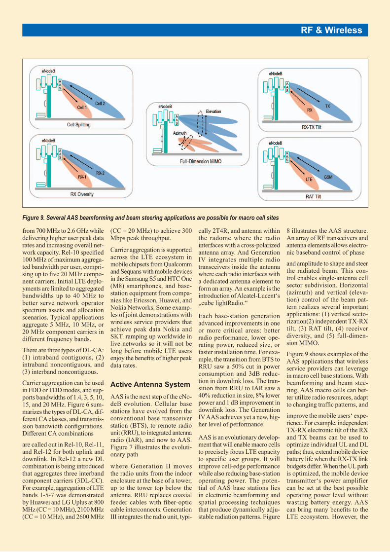
Figure 9 shows examples of the AAS applications that wireless service providers can leverage in macro cell base stations. With beamforming and beam stee-ring, AAS macro cells can bet-ter utilize radio resources, adapt to changing traffic patterns, and
improve the mobile users‘ expe-rience. For example, independent TX-RX electronic tilt of the RX and TX beams can be used to optimize individual UL and DL paths; thus, extend mobile device battery life when the RX-TX link budgets differ. When the UL path is optimized, the mobile device transmitter‘s power amplifier can be set at the best possible operating power level without wasting battery energy. AAS can bring many benefits to the LTE ecosystem. However, the
Figure 9. Several AAS beamforming and beam steering applications are possible for macro cell sites

66 hf-praxis 7/2016
RF & Wireless
RF properties of AAS base sta-tions differ from conventional antenna systems and this must be studied in detail. In Rel-12 a working group is studying AAS. A main objective of the 3GPP active antenna work item is to identify the RF requi-rements and conformance testing for AAS base stations. Some of the topics include adjacent-channel leakage ratio (ACLR), in-band/out-band emissions, receiver sensitivity, receiver blocker performance, and 3D channel modeling. recognized benefits of AAS are the primary reasons behind the 3GPP study: capacity gains by employing fle-xible cell splits with beam sha-ping and steering; elimination of cable attenuation and power losses; fewer components moun-ted on the tower top; and better network availability with trans-ceiver redundancy. The advent of AAS Generation IV base sta-tions promises higher levels of performance for macro cells and effective delivery of new 4G ser-vices like Voice-over-LTE and LTE-Broadcast.
Spatial Multiplexing with Downlink MIMO Transporting gigabit-per-second downlink peak data rates in a 100MHz carrier aggregation band-limited system requires spectral efficiency techniques beyond high-order modulation. As wireless communication links approach the limits of Shannon‘s capacity theorem, the spatial dimension must be exploited and, hence, spatial multiplexing with multiple antenna configu-rations must be adopted. LTE Rel-8 saw the inclusion of 2X2 and 4X4 MIMO with 4-layer transmission. Rel-10 extended this to 8X8 downlink MIMO, also called transmission mode 9 (TM9). Rel-12 explores ways to optimize 8X8 DL MIMO and includes an investigation of full-dimension MIMO (FD-MIMO), complimented by AAS. Adopting spatial multiplexing with 8X8 downlink MIMO can deliver an 8x increase in through-put without using more spectrum
bandwidth. In situations where communication link reliabi-lity is important or poor signal conditions exist, then down-link spatial diversity (transmit diversity) might be employed to obtain diversity gain and improve signal-to-interference-plus-noise-ratio (SINR). Impor-tant network performance gains can be realized with MIMO spa-tial multiplexing or MIMO spa-tial diversity. However, these advanced tech-niques require multiple anten-nas at both the eNodeB and the mobile user equipment (UE). Deploying 8x8 MIMO requires eight antennas at the eNodeB and UE, as shown in Figure 10. Because antenna spatial separa-tion is needed, it will be difficult to integrate eight antennas in a small-form-factor mobile device like a smartphone. However, 4X4 MIMO is prac-tical with new advancements in antenna development like that seen by SkyCross peat data rates have been demonstrated. Larger-form-factor devices like data-hungry notebook PCs will have an easier time integrating eight antennas. And because it is more practical and enjoyable to view high-definition (HD) video content on large-screen devices, tablets and mobile PCs
can take full advantage of mobile HD video with high-throughput 8X8 MIMO.
Moreover, since mobile video is a leading driver of growth in data traffic and considered a value-added feature for wire-less service providers, there is an important trend in the macro cell eNodeB to support multiple antennas with four- and eight-layer transmission.
Much of the foundation for downlink MIMO was completed in Rel-8 thru Rel-11 sessions. This included the development of transmission modes 1 thru 9, code book structure, channel state information (CSI) feed-back, demodulation reference signal (DM RS), downlink con-trol information (DCI) format, and dynamic switching between SU-MIMO and MU-MIMO. To improve spectral efficiency Rel-12 focuses on two CSI enhan-cements: (1) 4TX Precoding Matrix Index feedback, and (2) aperiodic feedback Physical Uplink Shared-Channel mode3-2. Rel-12 also begins initial stu-dies of FD-MIMO.
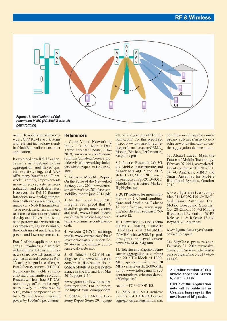
FD-MIMO unites AAS, 3D beamforming, and spatial multi-plexing to deliver efficient spec-trum utilization while increasing network capacity. The possibi-
lities of FD-MIMO are shown in Figure 11, where antenna beams can be precisely and independently focused on many mobile users at different azimuth and elevation planes. In Rel-10 and Rel-11 the MIMO features specifically addressed eNodeB antenna directivity in the azi-muth. Rel-12 explores ways to fully utilize the spatial domain.
To realize the FD-MIMO vision, further work is needed in 3D channel modeling, codebook design, feedback enhancements, and definitions for AAS radio requirements. Nevertheless, the first step, integrating multiple wideband radio transmitter chan-nels into a space-constrained antenna system, can be addressed with an innovative bits-to-RF solution. Part 2 of this appli-cation note reveals how direct-conversion RF-DAC technology can be embedded in AAS to red-uce transmitter operating power, minimize heat dissipation, and shrink circuit board area.
Conclusion This application note, Part 1 of this two-part series, explored the market forces that are driving global adoption of LTE-Advan-ced and discussed the evolution of 4G cellular base-station equip-
Figure 10. Spatial multiplexing with 8X8 MIMO requires eight antennas at both the eNodeB and the mobile user device
hf-praxis 7/2016 67
ment. The application note revie-wed 3GPP Rel-12 work items and relevant technology trends in eNodeB downlink transmitter applications.
It explained how Rel-12 enhan-cements in wideband carrier aggregation, multilayer spa-tial multiplexing, and AAS offer many benefits to 4G net-works, namely, improvements in coverage, capacity, network utilization, and peak data rates. However, the Rel-12 features introduce new analog integra-tion challenges when designing macro cell eNodeB transmitters. To be exact, designers will need to increase transmitter channel density and deliver ultra-wide-band performance with full car-rier frequency agility, bound by the constraints of small size, less power, and lower system cost.
Part 2 of this application note series introduces a disruptive radio solution that can help engi-neers shape new RF transmitter architectures and overcome Rel-12 analog integration challenges. Part 2 focuses on novel RF DAC technology that yields a single-chip radio transmitter solution. Readers will learn how RF DAC technology offers radio engi-neers a way to shrink size by 60%, reduce component count by 75%, and lower operating power by 1000mW per channel.
References 1. Cisco Visual Networking Index – Global Mobile Data Traffic Forecast Update, 2014-2019, www.cisco.com/c/en/us/solutions/collateral/service-pro-vider/visual-networking-index-vni/white_paper_c11-520862.html. 2. Ericsson Mobility Report, On the Pulse of the Networked Society, June 2014, www.erics-son.com/res/docs/2014/ericsson- mobility-report-june-2014.pdf. 3. Alcatel Lucent Blog, 2013 insights: real proof that 4G speed brings consumers, content and cash, www.alcatel- lucent.com/blog/2014/proof-4g-speed-brings-consumers-content-and-cash. 4. Verizon Q2CY14 earnings results, www.verizon.com/about/investors/quarterly-reports/2q-2014-quarter-earnings- confe-rence-call-webcast/. 5. SK Telecom Q2CY14 ear-nings results, www.sktelecom.com/en/ir_file/results.do. 6. GSMA Mobile Wireless Perfor-mance in the EU and US, May 2013, pages 9-10, www.gsmamobilewirelessper-formance.com/ For the report, see http://tinyurl.com/pp8ogf8. 7. GSMA, The Mobile Eco-nomy Report Series 2014, page
20, www.gsmamobileeco-nomy.com/. For this report see http://www.gsmamobilewire-lessperformance.com/GSMA_Mobile_Wireless_Performance_May2013.pdf.
8. Infonetics Research, 2G, 3G, 4G Mobile Infrastructure and Subscribers 4Q12 and 2012, slides 11-12, March 2013, www.infonetics.com/pr/2013/4Q12-Mobile-Infrastructure-Market-Highlights.asp.
9. 3GPP website for more infor-mation on CA band combina-tions and details on Release 12 specification, www.3gpp.org/specifications/releases/68-release-12.
10. Huawei and LG Uplus demo 800MHz (10MHz), 2100MHz ( 1 0 M H z ) a n d 2 6 0 0 M H z (20MHz) achieve 300Mbps peak throughput, pr.huawei.com/en/news/hw-343675-lg.htm.
11. Telestra and Ericsson demo carrier aggregation to combine one 20 MHz block of 1800-MHz spectrum with two 20 MHz carriers on the 2600-MHz band, www.telecomasia.net/content/telstra-ericsson-demo-450mbps-lte?
section=TOP+STORIES.
12. NSN, KT, SKT achieve world‘s first TDD-FDD carrier aggregation demonstration, nsn.
com/news-events/press-room/press- releases/nsn-kt-skt-achieve-worlds-first-tdd-fdd-car-rier-aggregation-demonstration.
13. Alcatel Lucent Maps the Future of Mobile Technology, February 07, 2011, www.alcatel-lucent.com/press/2011/002331. 14. 4G Americas, MIMO and Smart Antennas for Mobile Broadband Systems, October 2012,
w w w . 4 g a m e r i c a s . o r g /files/2114/0759/4301/MIMO_and_Smart_Antennas_for_Mobile_Broadband_Systems_Oct_2012x.pdf. 15. 4G Mobile Broadband Evolution, 3GPP Release 11 & Release 12 and Beyond, 4G Americas,
www.4gamericas.org/en/resour-ces/white-papers/.
16. SkyCross press release, February 24, 2014 www.sky-cross.com/news-and-events/press-release/mwc-2014-4x4-mimo/.
Figure 11. Applications of full-dimension MIMO (FD-MIMO) with 3D beamforming
RF & Wireless
A similar version of this article appeared March 6, 2015 in EDN. Part 2 of this application note will be published in German language in the next issue of hf-praxis.