Embed Size (px)
Citation preview
The most important thing we build is trust
PXILTE/LTE-A Downlink (FDD and TDD) Measurement SuiteData Sheet
• Designed for the production test of the base station RF, tailored for theevolving small cell test requirement
• Industry leading measurement speed and 3GPP specification exceededmeasurement accuracy.
• Ready to support the BS RF non-signaling measurement during the R&Ddesign stage. A good choice for the 7X24 regression test, advancedradio signal simulation and analysis application
• LTE-A Carrier Aggregation
• Global TDD and FDD LTE bands
• Production test focused transmitter and receiver RF characteristics measurement� Output Power� CCDF� Occupied Bandwidth� Adjacent Channel Leakage Ratio� Operating Band Unwanted Emissions� Frequency Error� EVM� Reference sensitivity level
� In-channel selectivity
The LTE/LTE-A downlink measurement suite is a collection of software tools for use with the PXI 3000 Series RF modular instruments for measuring the LTE FDD and TDD transmitter and receiver characteristics of the base station including small cell, in accordance with the methodsdescribed in 3GPP TS 36.141 V10.6.0.
The measurement suite combined with the excellent RF performance of PXI VSA and VSG modules, is suitable for the base station RF components test during design validation and production test stages.
• PXI Studio 2 provides a user interface for bench-top manual operation during design integration or trouble shooting with multiple views ofgraphical traces.
• Analysis component libraries provide low level remote programming interfaces for highly customized ATE system integration.
• IQCreator waveform generation tool (supplied separately) enables the generation of bespoke test waveforms for use in measuring the receiver characteristics of the RF components.
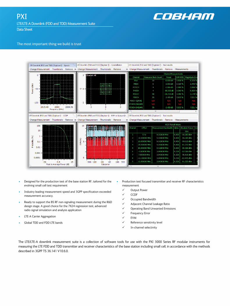
PXI Maestro is a unique automated production test tool which optimizes test speed through parallel and multi-thread measurement techniques. Integrated test plan editor and debug tools speed through the interface between R&D and production test and reduce the timefor new product introduction. PXI Maestro based solutions are available for customers who require a Turnkey production ATE solution.
Figure1. LTE Downlink Measurement Suite Software Component Architecture
IQCreator and PXI Studio 2 application software are supplied free of charge with PXI 3000 modules. Operation of the measurement suite orIQCreator requires simple activation of a license key option on the PXI 3000 hardware.
Further information for these applications is available through the following links:
• IQCreator
• PXI Studio 2
• PXI Maestro
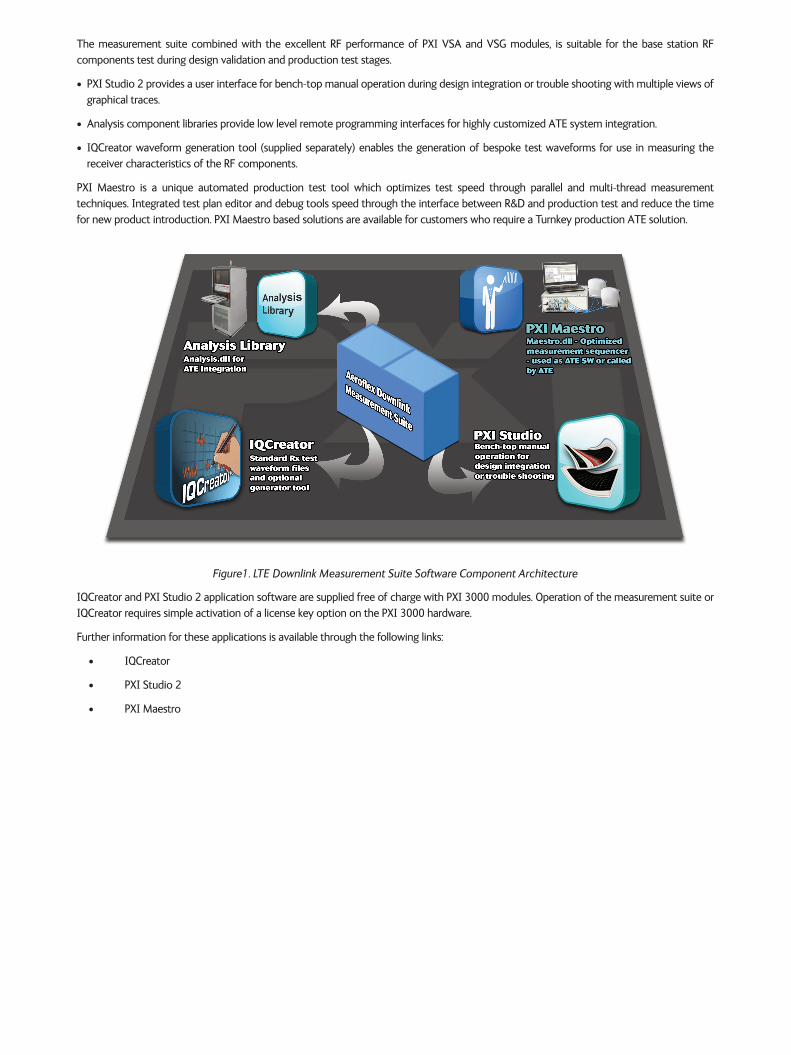
SPECIFICATIONS
All specifications are defined when used in conjunction with any 3030 Series or 3070A PXI RF Digitizer with option 117 LTE Downlink operating in all3GPP 36.141 specified global FDD and TDD LTE bands.
Tx measurements performed are in accordance with 3GPP 36.141 V10.6.0 Chapter 6.
Flexible options of stimulus are available for the receiver characteristics measurement in accordance with 3GPP 36.141 V10.6.0 Chapter 7.
Specifications are defined with the input signal at the RF digitizer tuned frequency and at the reference level unless otherwise stated.
TX MEASUREMENT CONFIGURATION
RF
Frequency User defined frequency (Hz), subject to the supported RF input of frequency range of the PXI RF digitizer
Band Valid value: FDD: 1-25 (excluding band 5, 16)
TDD: 33 to 43
Channel Valid value: Subject to selected band and bandwidth
Attenuation Mode Auto, Manual.
Auto: All Digitizer hardware setting are set automatically based on the specified DUT output level and TXpath loss
Manual: User control is provided for RF attenuation and preamplifier settings.
System
Bandwidth1.4, 3, 5, 10, 15 and 20 MHz
Up to 2x20 MHz Intra band Carrier aggregation
Downlink Mode FDD, TDD
Triggering
Triggering Type Immediate, External, Burst
Trigger source, delay and polarity can be configured manually when the external triggering type is selected.
Trigger level, delay and polarity can be configured manually when the burst triggering type is selected.
Measurements
Search Length Manual configurable
Sync Type Primary Sync signal, Cell-specific reference signal
User Carrier Filter Disabled, Enabled
Pilot Tracking(Amplitude/Time/Phase)
Enabled, Disabled
Test Model E-TM 1.1, E-TM 1.2, E-TM 2, E-TM 3.1, E-TM 3.2, E-TM 3.3, Manual Configuration
The Tx signal cell ID physical channel parameters and analysis options are manually configurable, in order todemodulate and analyze the non-standard 3GPP test model(1) Tx signals.
Footnote(1) The Tx signal with 7.5 kHz sub-carrier spacing, multi-cast operation (PMCH, MBSFN reference symbols) and UE-
specific/MBSFN reference symbols are not supported in the current release.
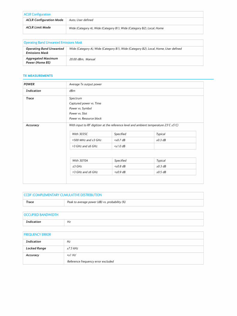
TX MEASUREMENTS
ACLR ConfigurationACLR Configuration Mode Auto, User defined
ACLR Limit Mode Wide (Category A), Wide (Category B1), Wide (Category B2), Local, Home
Operating Band Unwanted Emissions Mask
Operating Band UnwantedEmissions Mask
Wide (Category A), Wide (Category B1), Wide (Category B2), Local, Home, User defined
Aggregated MaximumPower (Home BS)
20.00 dBm, Manual
FREQUENCY ERROR
Indication Hz
Locked Range ±7.5 kHz
Accuracy <±1 Hz(
Reference frequency error excluded
OCCUPIED BANDWIDTH
Indication Hz
CCDF (COMPLEMENTARY CUMULATIVE DISTRIBUTION
Trace Peak to average power (dB) vs. probability (%)
POWER Average Tx output power
Indication dBm
Trace Spectrum
Captured power vs. Time
Power vs. Symbol
Power vs. Slot
Power vs. Resource block
Accuracy With input to RF digitizer at the reference level and ambient temperature 23°C ±5°C)
With 3035C Specified Typical
>500 MHz and ≤3 GHz <±0.7 dB ±0.3 dB
>3 GHz and ≤6 GHz <±1.0 dB
With 3070A Specified Typical
≤3 GHz <±0.8 dB ±0.3 dB
>3 GHz and ≤6 GHz <±0.9 dB ±0.5 dB
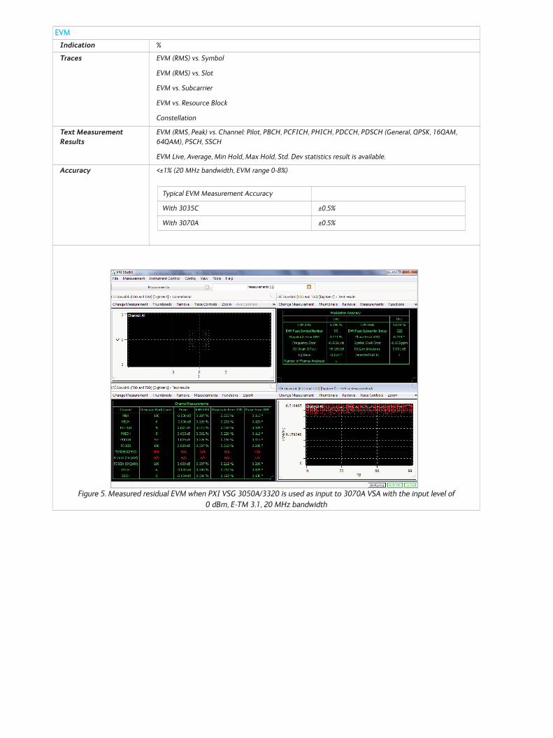
EVMIndication %
Traces EVM (RMS) vs. Symbol
EVM (RMS) vs. Slot
EVM vs. Subcarrier
EVM vs. Resource Block
Constellation
Text MeasurementResults
EVM (RMS, Peak) vs. Channel: Pilot, PBCH, PCFICH, PHICH, PDCCH, PDSCH (General, QPSK, 16QAM,64QAM), PSCH, SSCH
EVM Live, Average, Min Hold, Max Hold, Std. Dev statistics result is available.
Accuracy <±1% (20 MHz bandwidth, EVM range 0-8%)
Figure 5. Measured residual EVM when PXI VSG 3050A/3320 is used as input to 3070A VSA with the input level of 0 dBm, E-TM 3.1, 20 MHz bandwidth
Typical EVM Measurement Accuracy
With 3035C ±0.5%
With 3070A ±0.5%
OTHER TRACE MEASUREMENTS
Symbol Clock Error vs. Symbol Magnitude Error vs. Resource Block
Symbol Clock Error vs. Slot Phase Error RMS vs. Symbol
Magnitude Error RMS vs. Symbol Phase Error RMS vs. Slot
Magnitude Error RMS vs. Slot Phase Error vs. Subcarrier
Magnitude Error vs. Subcarrier Phase Error vs. Resource Block
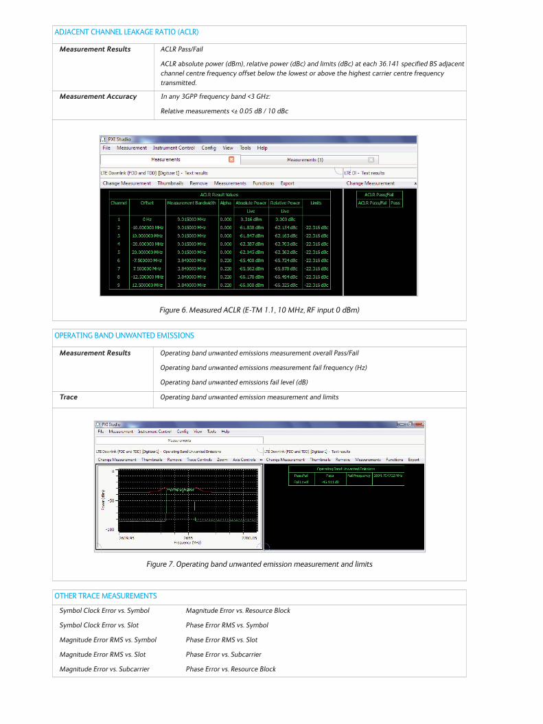
OPERATING BAND UNWANTED EMISSIONS
Measurement Results Operating band unwanted emissions measurement overall Pass/Fail
Operating band unwanted emissions measurement fail frequency (Hz)
Operating band unwanted emissions fail level (dB)
Trace Operating band unwanted emission measurement and limits
Figure 7. Operating band unwanted emission measurement and limits
ADJACENT CHANNEL LEAKAGE RATIO (ACLR)
Measurement Results ACLR Pass/Fail
ACLR absolute power (dBm), relative power (dBc) and limits (dBc) at each 36.141 specified BS adjacentchannel centre frequency offset below the lowest or above the highest carrier centre frequency transmitted.
Measurement Accuracy In any 3GPP frequency band <3 GHz:
Relative measurements <± 0.05 dB / 10 dBc
Figure 6. Measured ACLR (E-TM 1.1, 10 MHz, RF input 0 dBm)
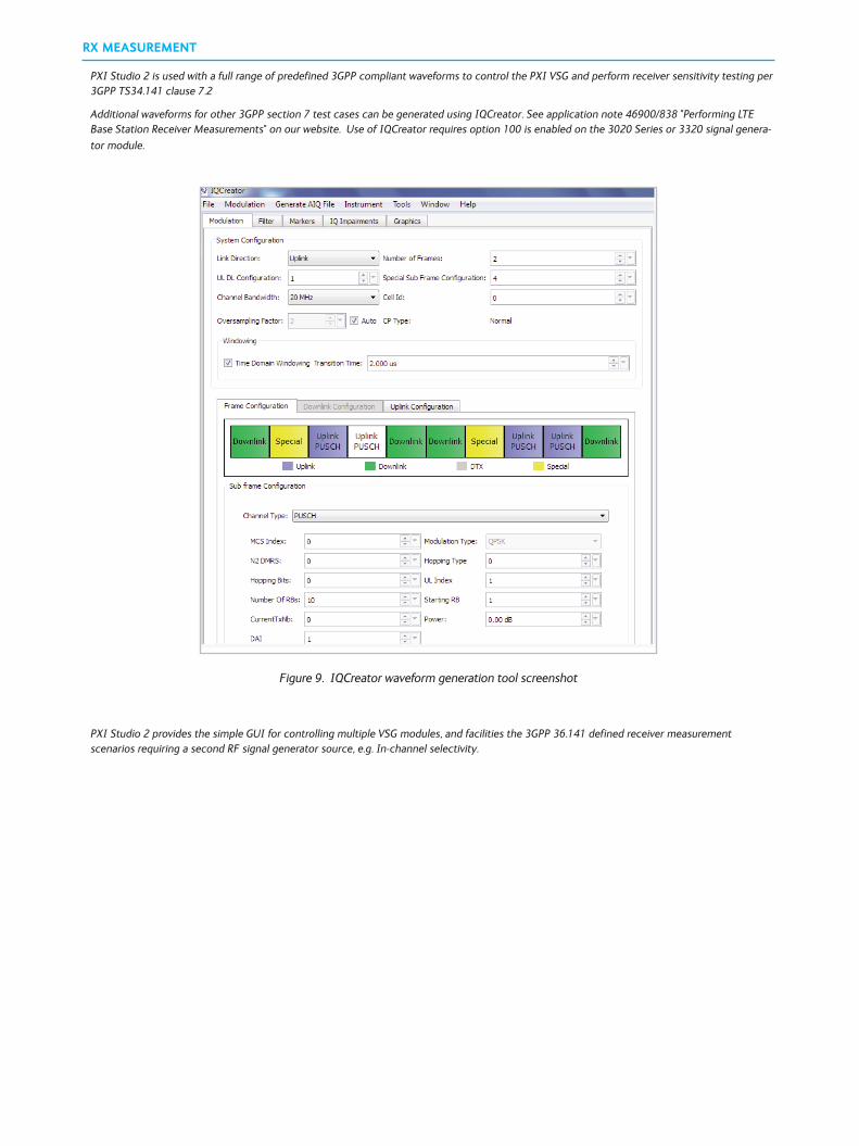
RX MEASUREMENT
PXI Studio 2 is used with a full range of predefined 3GPP compliant waveforms to control the PXI VSG and perform receiver sensitivity testing per3GPP TS34.141 clause 7.2
Additional waveforms for other 3GPP section 7 test cases can be generated using IQCreator. See application note 46900/838 "Performing LTEBase Station Receiver Measurements" on our website. Use of IQCreator requires option 100 is enabled on the 3020 Series or 3320 signal genera-tor module.
Figure 9. IQCreator waveform generation tool screenshot
PXI Studio 2 provides the simple GUI for controlling multiple VSG modules, and facilities the 3GPP 36.141 defined receiver measurement scenarios requiring a second RF signal generator source, e.g. In-channel selectivity.
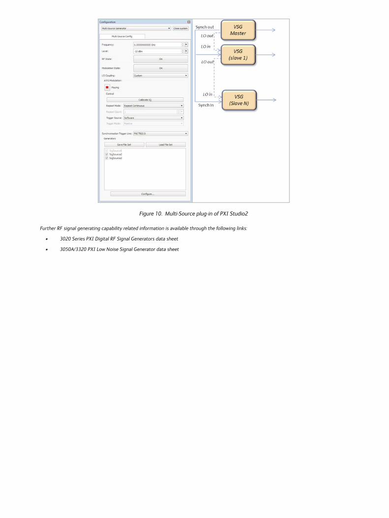
Figure 10. Multi-Source plug-in of PXI Studio2
Further RF signal generating capability related information is available through the following links:
• 3020 Series PXI Digital RF Signal Generators data sheet
• 3050A/3320 PXI Low Noise Signal Generator data sheet
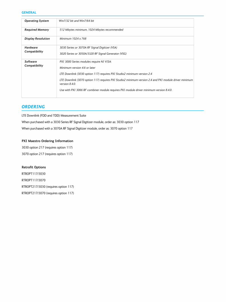
GENERAL
ORDERING
LTE Downlink (FDD and TDD) Measurement Suite
When purchased with a 3030 Series RF Signal Digitizer module, order as: 3030 option 117
When purchased with a 3070A RF Signal Digitizer module, order as: 3070 option 117
PXI Maestro Ordering Information
3030 option 217 (requires option 117)
3070 option 217 (requires option 117)
Retrofit Options
RTROPT117/3030
RTROPT117/3070
RTROPT217/3030 (requires option 117)
RTROPT217/3070 (requires option 117)
Operating System Win7/32 bit and Win7/64 bit
Required Memory 512 Mbytes minimum, 1024 Mbytes recommended
Display Resolution Minimum 1024 x 768
HardwareCompatibility
3030 Series or 3070A RF Signal Digitizer (VSA)
3020 Series or 3050A/3320 RF Signal Generator (VSG)
SoftwareCompatibility
PXI 3000 Series modules require NI VISA:
Minimum version 4.6 or later
LTE Downlink (3030 option 117) requires PXI Studio2 minimum version 2.4
LTE Downlink (3070 option 117) requires PXI Studio2 minimum version 2.4 and PXI module driver minimumversion 8.4.0.
Use with PXI 3066 RF combiner module requires PXI module driver minimum version 8.4.0.


www.cobham.com/wirelessCobham Wireless - Validation
Part No.46900/032, Issue 2, 07/15


![LTE PHY Layer Measurement Guide...4 LTE PHY Layer Measurement Guide LTE Downlink The LTE downlink can be set on six different frequency profiles, as follows: Channel Bandwidth [MHz]](https://img.pdfslide.net/doc/110x75/5e9903898496907a812cd628/lte-phy-layer-measurement-guide-4-lte-phy-layer-measurement-guide-lte-downlink.jpg)