Embed Size (px)
Citation preview

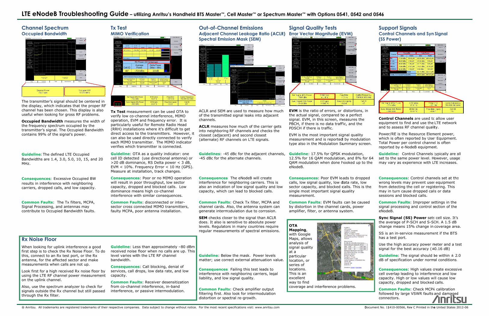
LTE eNodeB Troubleshooting Guide – utilizing Anritsu’s Handheld BTS Master™, Cell Master™ or Spectrum Master™ with Options 0541, 0542 and 0546
Visit us at www.anritsu.com
Start Here Use Over-the-Air (OTA) tests to spot-check a transmitter’s coverage and signal quality. Use the Direct Connect tests to check transmitter power and EVM when the OTA test results are ambiguous.
Troubleshooting Hints These two tables provide guidance from the first indication of a fault, a poor Key Performance Indicator (KPI), to the BTS Master, Cell Master or Spectrum Master test, and finally, to the field replaceable unit.
Key Performance Indicators vs. Test
Sync
Power
RS
Power
Occupied BW,
ACLR, & SEM
EVM (pk)
EVM (rms)
Freq Error
Rx Noise Floor
OTA EVM
Call/Session Blocking Power shortage x x x
Resource Block shortage x xx xx
UL Interference x xx
Call/Session Drop
Radio Link Timeout x x x x x x x
UL Interference x x
DL Interference x x x x x x
Test vs. BTS Field Replaceable Units Freq Ref Signal
Generation MCPA Filters Antenna
Antenna Down Tilt
Sync Power x xx x
RS Power x xx x
Occupied BW x xx xx
Adjacent Channel Leakage Ratio (ACLR)
x x xx x
Spectral Emission Mask (SEM) x x xx x
Error Vector Magnitude Peak (EVM pk)
x xx
Error Vector Magnitude EVM (rms)
x x x x
Frequency Error xx
OTA EVM x x x x x
x = probable, xx = most probable
Locating Over-the-Air Test Spots To test an eNodeB Over-the-Air (OTA) it is necessary to find a location with good Sync Signal (SS) dominance. The SS dominance measurements are ideal for this task. OTA testing requires SS dominance readings higher than 10 dB.
To find a good OTA test site, look for a place squarely in the sector, a block or two from the tower, and away from surfaces that may reflect radio waves. A directional antenna will help to screen out unwanted signals.
In some urban areas, locating a good OTA site can be difficult. In these cases, it may be quicker to connect to the BTS for testing.
Anritsu BTS Master™
Direct Connect Transmitter Tests Transmitter tests can be run while connected to the:
Output of the eNodeB (Point ”A”).
Test port (Point “B”) which is essentially the output of the Multi-Carrier Power Amplifier (MCPA).
Input to the MCPA (Point “C”) if the signal is accessible
Frequency reference system (Point “D”) for carrier frequency errors
The goal of these measurements is to increase data rate and capacity by accurate power settings, low out-of-channel emissions, and good signal quality tests. Good signals allow the cell to generate more revenue and provide a better return on investment.
The antenna is the last link in the transmission path. If connected at point “A”, it is helpful to sweep the antenna(s) at the same time, to ensure a high quality signal.
Multiple Sector Coverage Checks Sync Signal Power, Dominance, Cell ID, and EVM
Sync Signal (S-SS) affects cell size. S-SS is also used OTA to check coverage. It should be highest near the tower, declining to a minimum level at the handoff point. More information on SS is provided elsewhere in this guide.
Dominance: The strength of the strongest S-SS compared to the others.
EVM, RSRP, RSRQ, and SINR all indicate the quality of the received signal. In this screen, EVM is measured on the PBCH signal, so as to not be affected by traffic.
Cell, Group, and Sector ID: Identifies the source of the OTA signals detected.
Guidelines:
Dominance: Higher than 10 dB for OTA signal quality testing.
EVM: Established from a known good base station at a location where the dominance figure is over 10 dB.
Cell, Group, and Sector ID: Should be set as defined by engineering.
Consequences:
Poor Dominance: Poor spot to test the BTS OTA. May be a result of excessive coverage, which will result in a loss of system capacity due to excessive co-channel interference.
Poor EVM: Call drops, call blocking, low data rate, and low capacity.
Wrong Cell, Group or Sector ID: Dropped handoffs and island sectors.
Common Faults: Antenna down tilt, damaged antennas, control channel power settings, and co-channel interference.
Pass Fail measurements simplify OTA and Direct Connect Transmitter Test with user specified Limit sets
L
®
CO
Ttcu
Ottc
GBM
Crc
CSc
RWftam
Luo
Ast
LTE eNod
® Anritsu. All tra
Channel SOccupied B
The transmittthe display, wchannel has buseful when l
Occupied Bathe frequencytransmitter’s contains 99%
Guideline: ThBandwidths aMHz.
Consequencresults in intecarriers, drop
Common FauSignal Procescontribute to
Rx Noise FWhen lookingfirst step is tothis, connect antenna, for tmeasurement
Look first for using the LTEon the uplink
Also, use the signals outsidthrough the R
deB Trou
ademarks are reg
Spectrum Bandwidth
ter’s signal shwhich indicatebeen chosen. ooking for gr
andwidth mey spectrum ocsignal. The O
% of the signa
he defined LTre 1.4, 3.0, 5
ces: Excessiverference withpped calls, an
ults: The Txsing, and antOccupied Ba
Floor g for uplink ino check the Rto an Rx testthe affected sts when calls
a high receivE RF channel channel.
spectrum ande the Rx chaRx filter.
ublesho
gistered tradema
hould be centes that the pr This display ross RF proble
easures the wccupied by thOccupied Banal’s power.
TE Occupied 5.0, 10, 15, a
ve Occupied Bh neighboringd low capacit
x filters, MCPAtennas may ndwidth fault
nterference a Rx Noise Floort port, or the sector and m are not up.
ved Rx noise power measu
alyzer to chennel but still
ooting G
arks of their resp
tered in roper RF is also ems.
width of he dwidth
TxM
Txveoppa(Rdicaeave
and 20 Guce>2EVMe
BW g ty.
Cowicadoint
A,
ts.
Cosefa
good r. To do Rx ake
floor by urement
eck for passed
Gurelevba
Coseca
Cofroint
Guide – ut
pective companie
x Test MIMO Verific
x Test measuerify low co-cperation, EVMarticularly useRRH) installatrect access to
an also be useach MIMO traerifies which t
uideline: OTell ID detected20 dB dominaVM < 10%. Feasure at ins
onsequenceill result in poapacity, droppominance meterference wi
ommon Fauector cross coulty MCPA, p
uideline: Lesceived noise vel varies witandwidth.
onsequenceervices, call dapacity.
ommon Fauom co-channterference, o
tilizing Anr
es. Data subject
cation
urement can hannel interf
M and frequeneful for Remotions where ito the transmed directly consmitter. Thtransmitter is
TA as a qualitd (use directance, RS Delrequency Errtallation, trac
es: Poor or nooor throughpped and blockeans high co-cith similar co
lts: disconneonnected MIMpoor antenna
ss than appro floor when nth the LTE RF
es: Call blockdrops, low dat
lts: Receiverel interferenc
or passive inte
ritsu’s Hand
to change witho
be used OTAference, MIMOncy error. It ote Radio Heat’s difficult toitters. Howe
onnected to vhe MIMO indics connected.
ty indicator: otional antennta power < 3ror < 10 Hz (ck changes.
o MIMO operaut, low sectoked calls. Lochannel
onsequences.
ected or interMO transmitte installation.
oximately –8no calls are uF channel
ing, denial ofta rate, and l
r desensitizatce, in-band ermodulation
dheld BTS M
out notice. For th
A to O is ad
o get ever, it verify cator
OuAdjSpe
ACLof thchan
ACLintoclos(alte
one na) or 3 dB, GPS).
Gui-45
ation or ow
Conintealsocapa
r-ers,
Comchangen
80 dBm p. This
f low
tion
n.
SEMdoesleveregu
Guimat
Coninteliabi
Comfiltedisto
Master™, C
he most recent s
ut-of-Chanjacent Chaectral Emiss
LR and SEM ahe transmittennels.
LR measures neighboring est (adjacenternate) RF ch
delines: -45 dBc for the a
nsequences:rference for n
o an indicationacity, which c
mmon Faultsnnel cards. Aerate intermo
M checks closs. It also is s
els. Regulatorular measure
deline: Belotter; use corr
nsequences:rference withility, and low
mmon Faultsring first. Alsortion or spe
Cell Maste
specifications visi
nnel Emissnnel Leaka
sion Mask (S
re used to med signal leak
how much of RF channels t) and secondhannels on LT
5 dBc for the alternate cha
The eNodeBneighboring cn of low signacan lead to b
s: Check Tx fAlso, the anteodulation due
ser to the signensitive to abrs in many coments of spe
w the mask. ect external a
Failing this th neighboring signal qualit
s: Check ampso look for intctral re-grow
r™ or Spec
it: www.anritsu.c
sions age Ratio (ASEM)
easure how mks into adjace
f the carrier g and checks td closest TE signals.
adjacent channels.
B will create carriers. This al quality andlocked calls.
filter, MCPA anna system ce to corrosion
nal than ACLRbsolute poweountries requiectral emissio
Power levelsattenuation v
test leads to g carriers, legy.
plifier output termodulation
wth.
ctrum Mast
com
ACLR)
much ent
gets the
SignError
EVMthe asignaPBCHPDSC
EVM meastype
nnels, Guid12.5QAMeNod
is d low
Conscallssectosinglmeas
and can n.
Comby damp
R r ire
ons.
OTAMapwith Mapsanalysignaat a partilocatserielocatThis exceway cove
s value.
gal
n
ter™ with O
nal Qualitr Vector Ma
M is the ratio oactual signal,al. EVM, in thH, if there is CH if there is
is the most isurement and also in the M
deline: 17.5%% for 16 QA modulation
deB.
sequences: , low signal qor capacity, ae most imposurement.
mmon Faultsistortion in thlifier, filter, o
A pping, Google s, allows ysis of al quality
cular tion, or es of tions. is an llent to find erage and inte
Options 054
ty Tests agnitude (E
of errors, or compared to
his screen, mno data traffi traffic.
important sigd is reported
Modulation Su
% for QPSK mM modulationwhen done h
Poor EVM leaquality, low dand blocked crtant signal q
s: EVM faults he channel caor antenna sy
erference pro
41, 0542 a
D
EVM)
distortions, io a perfect
measures the fic, and the
gnal quality d by modulatiummary scre
modulation, n, and 8% fohooked up to
ads to droppdata rate, lowcalls. This is tquality
can be causeards, power ystem.
oblems.
nd 0546
Document No. 11
n
on een.
SuppCont(SS P
Contrequipand to
PowerwhichTotal report
or 64 the
Guideset tomay v
ed w the
Conswrongfrom may isessio
ed CommsignaeNode
Sync the avchang
SS is has a
Use thsigna
GuidedB of
Conscell ovcapaccapac
Commfollowconne
1410-00566, Rev
port Signatrol Channeower)
rol Channelsment to find o assess RF c
r/RE is the Reh is often repo Power per coted by e-Nod
eline: Contro the same povary as exper
equences: Cg levels may detecting then turn cause
ons and block
mon Faults:l processing aeB.
Signal (SS)verage of P-Sge means 15%
an in-service test port.
he high accurl for the best
eline: The si specification
equences: Hverlap leadincity. High or lcity, dropped
mon Faults:wed by large Vectors.
v C Printed in the
als els and Syn
s are used to and use the channel quali
esource Elemorted by Useontrol channedeB equipmen
rol Channels tower level. Hrience with LT
Control chann prevent usere cell or regis dropped callked calls.
Improper seand control s
) Power setsSCH and S-SC% change in
e measureme
racy power mt accuracy (±
gnal should bn under norm
High values cg to interfereow values wi and blocked
Check MCPAVSWR faults
e United States 2
Signal
o allow user LTE network ty.
ment power, r Equipment.el is often nt.
typically are owever, usagTE increases.
nels set at ther equipment tering. This s or data
ettings in the ection of the
s cell size. It’sCH. A 1.5 dB coverage are
ent if the BTS
meter and a te0.16 dB)
be within ± 2al conditions.
reate excessence and low ll cause low calls.
A calibration and damaged
012-06
all ge
e
s ea.
est
.0
ive
d