Embed Size (px)
Citation preview
University of Nebraska - LincolnDigitalCommons@University of Nebraska - LincolnComputer & Electronics Engineering FacultyPublications
Computer & Electronics Engineering, Departmentof
1-1-2012
LTE PHY Performance Analysis under 3GPPStandards ParametersFahimeh RezaeiUniversity of Nebraska-Lincoln, [email protected]
Michael HempelUniversity of Nebraska Lincoln, [email protected]
Hamid SharifUniversity of Nebraska-Lincoln, [email protected]
Follow this and additional works at: http://digitalcommons.unl.edu/computerelectronicfacpubPart of the Computer Engineering Commons
This Article is brought to you for free and open access by the Computer & Electronics Engineering, Department of at DigitalCommons@University ofNebraska - Lincoln. It has been accepted for inclusion in Computer & Electronics Engineering Faculty Publications by an authorized administrator ofDigitalCommons@University of Nebraska - Lincoln.
Rezaei, Fahimeh; Hempel, Michael; and Sharif, Hamid, "LTE PHY Performance Analysis under 3GPP Standards Parameters" (2012).Computer & Electronics Engineering Faculty Publications. Paper 82.http://digitalcommons.unl.edu/computerelectronicfacpub/82
LTE PHY Performance Analysis under 3GPP
Standards Parameters
Fahimeh Rezaei, Michael Hempel, Hamid Sharif
Department of Computer and Electronics Engineering
University of Nebraska-Lincoln, Omaha, NE, USA
{frezaei, mhempel, hsharif}@unlnotes.unl.edu
Abstract— Long Term Evolution (LTE) has been introduced by
3GPP (3rd Generation Partnership Project) and is poised to
dominate the 4th generation (4G) of mobile telecommunication
networks. In this article, we present an in-depth analysis of the
LTE physical layer’s characteristics and its performance. Our
work is unique in providing a detailed performance study based
on Release 8 of the 3GPP standard. Several works have discussed
the LTE performance; however, most have been restricted to
limited scenarios. Our work shows a more comprehensive
investigation of the maximum data throughput under different
conditions and scenarios. Our performance study includes TDD
and FDD operational modes for uplink and downlink
transmissions in different antenna diversity schemes, data
modulation, and code rates. Our results show that LTE (3GPP-
Release 8) supports downlink throughputs of up to 300Mbps and
for the uplink a throughput of up to 75 Mbps.
Keywords-LTE; Performance; 3GPP standard; PHY; FDD; TDD;
OFDM; SC-FDMA; frame layout
I. INTRODUCTION
3GPP specified LTE [1-7], also called E-UTRA (Evolved- Universal Terrestrial Radio Access), to promote HSPA (High Speed Packet Access) performance through reducing overhead. LTE Downlink modulation is based on OFDM (Orthogonal Frequency Division Multiplex) which provides multi user access, robustness to time dispersion of radio channel, and low complexity for receiver design. SC-FDMA (Single Carrier Frequency Division Multiple Access) is employed in uplink that provides low peak-to-average power ratio.
LTE supports both FDD (Frequency Division Duplex) and TDD (Time Division Duplex) schemes, resulting in different frame structures in the time domain. In the frequency domain, different numbers of Resource Blocks (RBs) can be addressed based on the system bandwidth, which varies from 1.4MHz to 20MHz. A single RB consists of a group of carriers for transferring data. Each RB is 0.5ms in time domain and 180 kHz in frequency domain. Depending on the cyclic prefix mode and subcarrier spacing, the number of subcarriers and OFDM symbols in downlink (SC-FDMA symbols in Uplink) is different for each RB [1].
The rest of the paper presents a literature review in section II, the E-UTRA architecture overview in section III, and a general description of the LTE physical layer in section IV. In section V our LTE performance results are presented, with our conclusions shown in section VI.
II. LITERATURE REVIEW
Different characteristics and features of LTE have been presented in the literature. In [8], an overview of LTE specifications is provided and its performance is verified by simulation results. Comprehensive description of the link layer protocols and the interaction between protocol layers is discussed in [9]. Physical layer characteristics and features are investigated in [10] and the results show how different features such as adaptive modulation, scheduling, and multi antenna transmission schemes impact the spectral efficiency. However, the throughput analysis is limited to SISO scenarios. Another important consideration is the performance comparison of WiMAX and LTE based on different scenarios. In [11], the presented results illustrate that LTE is better than WiMAX with respect to spectrum efficiency, average user throughput, and cell edge bit rate gains for both TDD and FDD operations. This study also shows the results for 10 MHz system bandwidth. In [12] the performance assessment is limited to downlink and FDD operation only and the results present better radio performance for LTE because of the lower overhead. In addition to performance comparisons, analogous specifications and technologies are collated in different publications. For instance, the work in [13] classifies MIMO configurations in LTE and WiMAX, while [14] describes relay technologies for both communication standards. However, the large variations in the reported performance results prompted us to take a more in-depth analysis of the LTE specifications and develop a comprehensive and detailed evaluation of the LTE performance.
In this study, we model and simulate an LTE link with exclusion of all the overhead subcarrier allocations of control and broadcast channels as well as reference signals. We also considered 20 MHz system bandwidth in order to analyze the maximum throughput possible for different scenarios. Moreover, our performance study includes TDD and FDD operational modes in different antenna diversity schemes, data modulation, and code rates. The results of our study are presented in this paper.
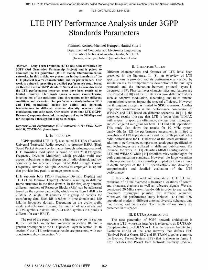
III. E-UTRA ARCHITECTURE
The next generation of 3GPP network architecture is known as LTE, whose air interface is referred to as E-UTRAN. Complementing E-UTRAN in LTE is the System Architecture Evolution (SAE) of the core network that defines EPC (Evolved Packet Core). EPC and EUTRAN together comprise the Evolved Packet System (EPS) that is shown in figure 1. EPC includes the Packet Data Network Gateway (P-GW),
2011 IEEE 16th International Workshop on Computer Aided Modeling and Design of Communication Links and Networks (CAMAD)
978-1-61284-282-0/11/$26.00 ©2011 IEEE 102
doi: 10.1109/CAMAD.2011.5941095
Serving Gateway (S-GW), Mobility Management Entity (MME), Home Subscriber Service (HSS), Policy Control and Charging Rules Function (PCRF)[3].
P-GW operates as an IP anchor and connects UE to the external packet data network. P-GW filters the downlink user IP packets and performs policy enforcements. User IP packets are transferred via S-GW that is also operating as a local mobility anchor when UE moves between eNBs. While P-GW can be considered as a mobility anchor between 3GPP and non-3GPP technologies, S-GW operates as mobility anchor between other 3GPP technologies. MME is responsible for functionalities such as user authentication, bearer management, and ideal mode UE tracking UE and core network by Non-Access Stratum (NAS) protocol. The information on the Packet Data Networks (PDNs) to which the UE can connect is located in HSS. PCRF manages charging functionalities and policy control as well as authorizing QoS.
Table 1. List of PHY Channels
PHY Channel Name Acronym
Physical Broadcast Channel PBCH
Physical Multicast Channel PMCH
Physical Downlink Shared Channel PDSCH
Physical Uplink Shared Channel PUSCH
Physical Downlink Control Channel PDCCH
Physical Random Access Channel PRACH
Physical Uplink Control Channel PUCCH
LTE radio access consists of four protocol layers: PHY, MAC, Radio Link Control (RLC), and Packet Data Convergence Protocol (PDCP). PHY and MAC utilize transport blocks to exchange information. At the PHY layer, several channels are allocated for data and control communication as specified in table 1.
IV. LTE PHY DESCRIPTION
LTE physical layer supports multiple users in downlink using OFDM (Orthogonal Frequency Division Multiplexing) and multiple access in uplink using SC-FDMA (Single Carrier-Frequency Division Multiple Access). However, whereas OFDM is a multi-carrier scheme, SC-FDMA is a single-carrier channel access scheme that provides the advantage of a low Peak-to-Average-Power Ratio (PAPR). LTE operates either
using FDD (Frequency Division Duplexing) or TDD (Time Division Duplexing).
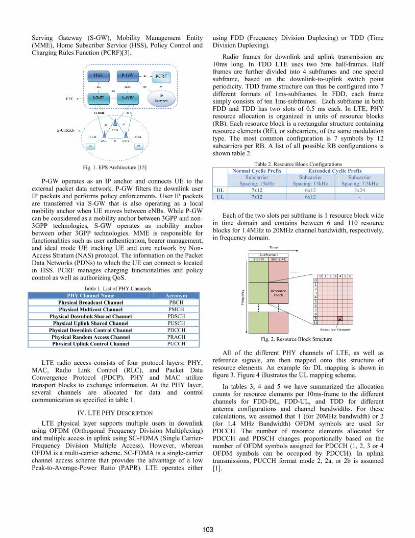
Radio frames for downlink and uplink transmission are 10ms long. In TDD LTE uses two 5ms half-frames. Half frames are further divided into 4 subframes and one special subframe, based on the downlink-to-uplink switch point periodicity. TDD frame structure can thus be configured into 7 different formats of 1ms-subframes. In FDD, each frame simply consists of ten 1ms-subframes. Each subframe in both FDD and TDD has two slots of 0.5 ms each. In LTE, PHY resource allocation is organized in units of resource blocks (RB). Each resource block is a rectangular structure containing resource elements (RE), or subcarriers, of the same modulation type. The most common configuration is 7 symbols by 12 subcarriers per RB. A list of all possible RB configurations is shown table 2.
Table 2. Resource Block Configurations
Normal Cyclic Prefix Extended Cyclic Prefix
Subcarrier
Spacing: 15kHz
Subcarrier
Spacing: 15kHz
Subcarrier
Spacing: 7.5kHz
DL 7x12 6x12 3x24
UL 7x12 6x12 -
Each of the two slots per subframe is 1 resource block wide in time domain and contains between 6 and 110 resource blocks for 1.4MHz to 20MHz channel bandwidth, respectively, in frequency domain.
All of the different PHY channels of LTE, as well as reference signals, are then mapped onto this structure of resource elements. An example for DL mapping is shown in figure 3. Figure 4 illustrates the UL mapping scheme.
In tables 3, 4 and 5 we have summarized the allocation counts for resource elements per 10ms-frame to the different channels for FDD-DL, FDD-UL, and TDD for different antenna configurations and channel bandwidths. For these calculations, we assumed that 1 (for 20MHz bandwidth) or 2 (for 1.4 MHz Bandwidth) OFDM symbols are used for PDCCH. The number of resource elements allocated for PDCCH and PDSCH changes proportionally based on the number of OFDM symbols assigned for PDCCH (1, 2, 3 or 4 OFDM symbols can be occupied by PDCCH). In uplink transmissions, PUCCH format mode 2, 2a, or 2b is assumed [1].
Resource Block
Slot 2i Slot 2i+1Subframe i
Time
Freq
uenc
y
0 1 2 3 4 5 60123456789
11
Resource Element
Fig. 2. Resource Block Structure
Fig. 1. EPS Architecture [15]
103
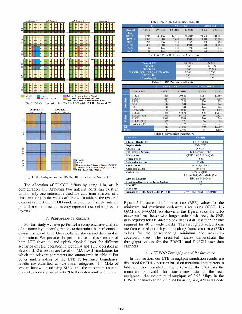
The allocation of PUCCH differs by using 1,1a, or 1b configuration [1]. Although two antenna ports can exist in uplink, only one antenna is used for data transmissions at a time, resulting in the values of table 4. In table 5, the resource element calculation in TDD mode is based on a single antenna port. Therefore, these tables only represent a subset of possible layouts.
V. PERFORMANCE RESULTS
For this study we have performed a comprehensive analysis of all frame layout configurations to determine the performance characteristics of LTE. Our results are shown and discussed in this section. We provide the performance analysis results of both LTE downlink and uplink physical layer for different scenarios of FDD operation in section A and TDD operation in Section B. Our results are based on MATLAB simulations for which the relevant parameters are summarized in table 6. For better understanding of the LTE Performance boundaries, results are classified as two main categories: 1.4 MHz of system bandwidth utilizing SISO, and the maximum antenna diversity mode supported with 20MHz in downlink and uplink.
Table 3. FDD-DL Resource Allocation
SISO MIMO 2x2 MIMO 4x4
Channel
BW
1.4 MHz 20 MHz 1.4 MHz 20 MHz 1.4 MHz 20 MHz
PDSCH 7,716 149,436 14,736 286,896 28,608 541,888
PDCCH 1,320 10,000 2,400 16000 3,840 16,000
PBCH 276 276 528 528 960 960
Ref S. 480 8,000 960 16000 1440 24,000
P-SS 144 144 288 288 576 576
S-SS 144 144 288 288 576 576
Table 4. FDD-UL Resource Allocation
SISO
Channel BW 1.4 MHz 20 MHz
PUSCH 5,760 141,120
PUSCH RS 1,200 23,760
PUCCH (CQI, HARQ ACK/NACK) 2,760 2,760
PUCCH RS 960 960
Sounding RS 120 120
Table 5. TDD Resource Allocation
Frame Mode 0 Frame Mode 5
Channel BW 1.4 MHz 20 MHz 1.6 MHz 20 MHz
Dow
nli
nk
PDSCH 1,236 29,580 6,204 119,580 PDCCH 264 2000 1,056 8000 PBCH 276 276 276 276 P-SS 144 144 144 144 S-SS 144 144 144 144 Ref Signals 96 1600 384 4600
Up
lin
k PUSCH 3,456 84,672 576 14,112
PUSCH (RS) 576 14,112 96 2,352 PUCCH 1368 1368 240 240 PUCCH (RS) 576 576 96 96 Sounding RS 72 72 24 24
GP 1,440 24,000 840 12,000 Pilots 144 2,400 84 1,200
Table 6. Simulation Parameters Parameter Value(s)
Channel Bandwidth 1.4, 20 (MHz)
Duplex Mode FDD, TDD
Channel Type AWGN
FEC Coding Scheme Turbo coding, R=1/3
Modulation QPSK, 16-QAM, 64-QAM
Frame Period 10 ms
Subcarrier spacing 15 kHz
Cyclic prefix Normal(4.69us)
Code Block Sizes 40, 6144
Code Rates 0.75 for QPSK,
0.85 for 16-QAM and 64-QAM
Antenna Diversity SISO and MIMO4x4
Maximum Iteration for Turbo Coding 10
Min BER 10-9
Max BER 10-4
Number of OFDM Symbols for PDCCH 2 for 1.4 MHz and 1 for 20MHz
Figure 5 illustrates the bit error rate (BER) values for the minimum and maximum codeword sizes using QPSK, 16-QAM and 64-QAM. As shown in this figure, since the turbo coder performs better with longer code block sizes, the SNR gain required for a 6144-bit block size is 4 dB less than the one required for 40-bit code blocks. The throughput calculations are then carried out using the resulting frame error rate (FER) values for the corresponding minimum and maximum codeword sizes. The presented figures demonstrate the throughput values for the PDSCH and PUSCH user data channels.
A. LTE FDD Throughput and Performance
In this section, our LTE throughput simulation results are discussed for FDD operation based on mentioned parameters in table 6. As presented in figure 6, when the eNB uses the minimum bandwidth for transferring data to the user equipment, the maximum throughput of 3.93 Mbps in the PDSCH channel can be achieved by using 64-QAM and a code
Fig. 4. UL Configuration for 20MHz FDD with 15kHz, Normal CP
Fig. 3. DL Configuration for 20MHz FDD with 15 kHz, Normal CP
104
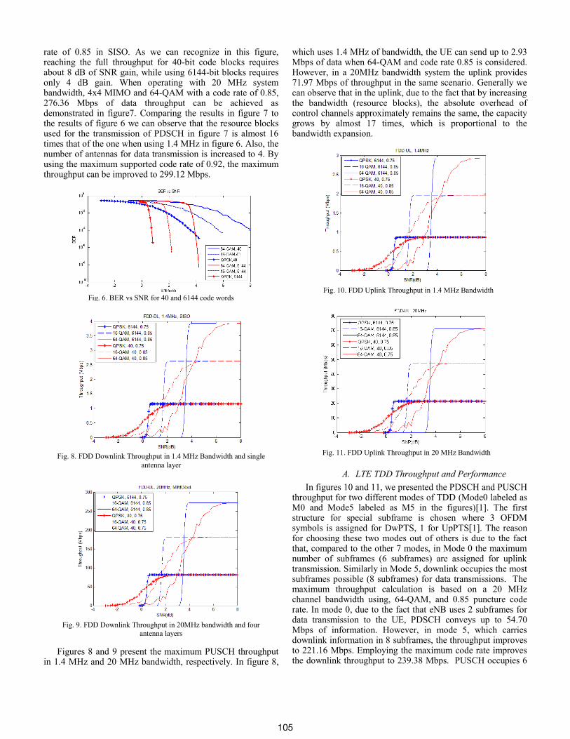
rate of 0.85 in SISO. As we can recognize in this figure, reaching the full throughput for 40-bit code blocks requires about 8 dB of SNR gain, while using 6144-bit blocks requires only 4 dB gain. When operating with 20 MHz system bandwidth, 4x4 MIMO and 64-QAM with a code rate of 0.85, 276.36 Mbps of data throughput can be achieved as demonstrated in figure7. Comparing the results in figure 7 to the results of figure 6 we can observe that the resource blocks used for the transmission of PDSCH in figure 7 is almost 16 times that of the one when using 1.4 MHz in figure 6. Also, the number of antennas for data transmission is increased to 4. By using the maximum supported code rate of 0.92, the maximum throughput can be improved to 299.12 Mbps.
Figures 8 and 9 present the maximum PUSCH throughput in 1.4 MHz and 20 MHz bandwidth, respectively. In figure 8,
which uses 1.4 MHz of bandwidth, the UE can send up to 2.93 Mbps of data when 64-QAM and code rate 0.85 is considered. However, in a 20MHz bandwidth system the uplink provides 71.97 Mbps of throughput in the same scenario. Generally we can observe that in the uplink, due to the fact that by increasing the bandwidth (resource blocks), the absolute overhead of control channels approximately remains the same, the capacity grows by almost 17 times, which is proportional to the bandwidth expansion.
A. LTE TDD Throughput and Performance
In figures 10 and 11, we presented the PDSCH and PUSCH throughput for two different modes of TDD (Mode0 labeled as M0 and Mode5 labeled as M5 in the figures)[1]. The first structure for special subframe is chosen where 3 OFDM symbols is assigned for DwPTS, 1 for UpPTS[1]. The reason for choosing these two modes out of others is due to the fact that, compared to the other 7 modes, in Mode 0 the maximum number of subframes (6 subframes) are assigned for uplink transmission. Similarly in Mode 5, downlink occupies the most subframes possible (8 subframes) for data transmissions. The maximum throughput calculation is based on a 20 MHz channel bandwidth using, 64-QAM, and 0.85 puncture code rate. In mode 0, due to the fact that eNB uses 2 subframes for data transmission to the UE, PDSCH conveys up to 54.70 Mbps of information. However, in mode 5, which carries downlink information in 8 subframes, the throughput improves to 221.16 Mbps. Employing the maximum code rate improves the downlink throughput to 239.38 Mbps. PUSCH occupies 6
Fig. 11. FDD Uplink Throughput in 20 MHz Bandwidth
Fig. 10. FDD Uplink Throughput in 1.4 MHz Bandwidth
Fig. 9. FDD Downlink Throughput in 20MHz bandwidth and four
antenna layers
Fig. 8. FDD Downlink Throughput in 1.4 MHz Bandwidth and single
antenna layer
Fig. 6. BER vs SNR for 40 and 6144 code words
105
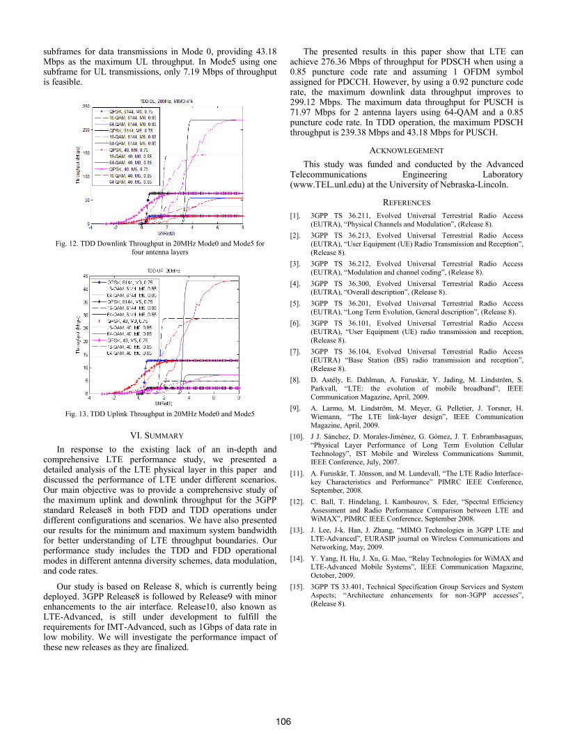
subframes for data transmissions in Mode 0, providing 43.18 Mbps as the maximum UL throughput. In Mode5 using one subframe for UL transmissions, only 7.19 Mbps of throughput is feasible.
VI. SUMMARY
In response to the existing lack of an in-depth and comprehensive LTE performance study, we presented a detailed analysis of the LTE physical layer in this paper and discussed the performance of LTE under different scenarios. Our main objective was to provide a comprehensive study of the maximum uplink and downlink throughput for the 3GPP standard Release8 in both FDD and TDD operations under different configurations and scenarios. We have also presented our results for the minimum and maximum system bandwidth for better understanding of LTE throughput boundaries. Our performance study includes the TDD and FDD operational modes in different antenna diversity schemes, data modulation, and code rates.
Our study is based on Release 8, which is currently being deployed. 3GPP Release8 is followed by Release9 with minor enhancements to the air interface. Release10, also known as LTE-Advanced, is still under development to fulfill the requirements for IMT-Advanced, such as 1Gbps of data rate in low mobility. We will investigate the performance impact of these new releases as they are finalized.
The presented results in this paper show that LTE can achieve 276.36 Mbps of throughput for PDSCH when using a 0.85 puncture code rate and assuming 1 OFDM symbol assigned for PDCCH. However, by using a 0.92 puncture code rate, the maximum downlink data throughput improves to 299.12 Mbps. The maximum data throughput for PUSCH is 71.97 Mbps for 2 antenna layers using 64-QAM and a 0.85 puncture code rate. In TDD operation, the maximum PDSCH throughput is 239.38 Mbps and 43.18 Mbps for PUSCH.
ACKNOWLEGEMENT
This study was funded and conducted by the Advanced Telecommunications Engineering Laboratory (www.TEL.unl.edu) at the University of Nebraska-Lincoln.
REFERENCES
[1]. 3GPP TS 36.211, Evolved Universal Terrestrial Radio Access
(EUTRA), “Physical Channels and Modulation”, (Release 8).
[2]. 3GPP TS 36.213, Evolved Universal Terrestrial Radio Access
(EUTRA), “User Equipment (UE) Radio Transmission and Reception”,
(Release 8).
[3]. 3GPP TS 36.212, Evolved Universal Terrestrial Radio Access
(EUTRA), “Modulation and channel coding”, (Release 8).
[4]. 3GPP TS 36.300, Evolved Universal Terrestrial Radio Access (EUTRA), “Overall description”, (Release 8).
[5]. 3GPP TS 36.201, Evolved Universal Terrestrial Radio Access
(EUTRA), “Long Term Evolution, General description”, (Release 8).
[6]. 3GPP TS 36.101, Evolved Universal Terrestrial Radio Access
(EUTRA), “User Equipment (UE) radio transmission and reception,
(Release 8).
[7]. 3GPP TS 36.104, Evolved Universal Terrestrial Radio Access
(EUTRA) “Base Station (BS) radio transmission and reception”,
(Release 8).
[8]. D. Astély, E. Dahlman, A. Furuskär, Y. Jading, M. Lindström, S.
Parkvall, “LTE: the evolution of mobile broadband”, IEEE
Communication Magazine, April, 2009.
[9]. A. Larmo, M. Lindström, M. Meyer, G. Pelletier, J. Torsner, H.
Wiemann, “The LTE link-layer design”, IEEE Communication
Magazine, April, 2009.
[10]. J J. Sánchez, D. Morales-Jiménez, G. Gómez, J. T. Enbrambasaguas,
“Physical Layer Performance of Long Term Evolution Cellular
Technology”, IST Mobile and Wireless Communications Summit, IEEE Conference, July, 2007.
[11]. A. Furuskär, T. Jönsson, and M. Lundevall, “The LTE Radio Interface-
key Characteristics and Performance” PIMRC IEEE Conference, September, 2008.
[12]. C. Ball, T. Hindelang, I. Kambourov, S. Eder, “Spectral Efficiency
Assessment and Radio Performance Comparison between LTE and WiMAX”, PIMRC IEEE Conference, September 2008.
[13]. J. Lee, J-k. Han, J. Zhang, “MIMO Technologies in 3GPP LTE and
LTE-Advanced”, EURASIP journal on Wireless Communications and
Networking, May, 2009.
[14]. Y. Yang, H. Hu, J. Xu, G. Mao, “Relay Technologies for WiMAX and LTE-Advanced Mobile Systems”, IEEE Communication Magazine,
October, 2009.
[15]. 3GPP TS 33.401, Technical Specification Group Services and System Aspects; “Architecture enhancements for non-3GPP accesses”,
(Release 8).
Fig. 13. TDD Uplink Throughput in 20MHz Mode0 and Mode5
Fig. 12. TDD Downlink Throughput in 20MHz Mode0 and Mode5 for
four antenna layers
106